Posted on Leave a comment

IC Decapping: The Process

As I’ve been posting some photos of decapped ICs lately, I thought I’d share the process I use personally for those that might want to give it a go 😉

The usual method for removing the epoxy package from the silicon is to use hot, concentrated Nitric Acid. Besides the obvious risks of having hot acids around, the decomposition products of the acid, namely NO² (Nitrogen Dioxide) & NO (Nitrogen Oxide), are toxic and corrosive. So until I can get the required fume hood together to make sure I’m not going to corrode the place away, I’ll leave this process to proper labs ;).

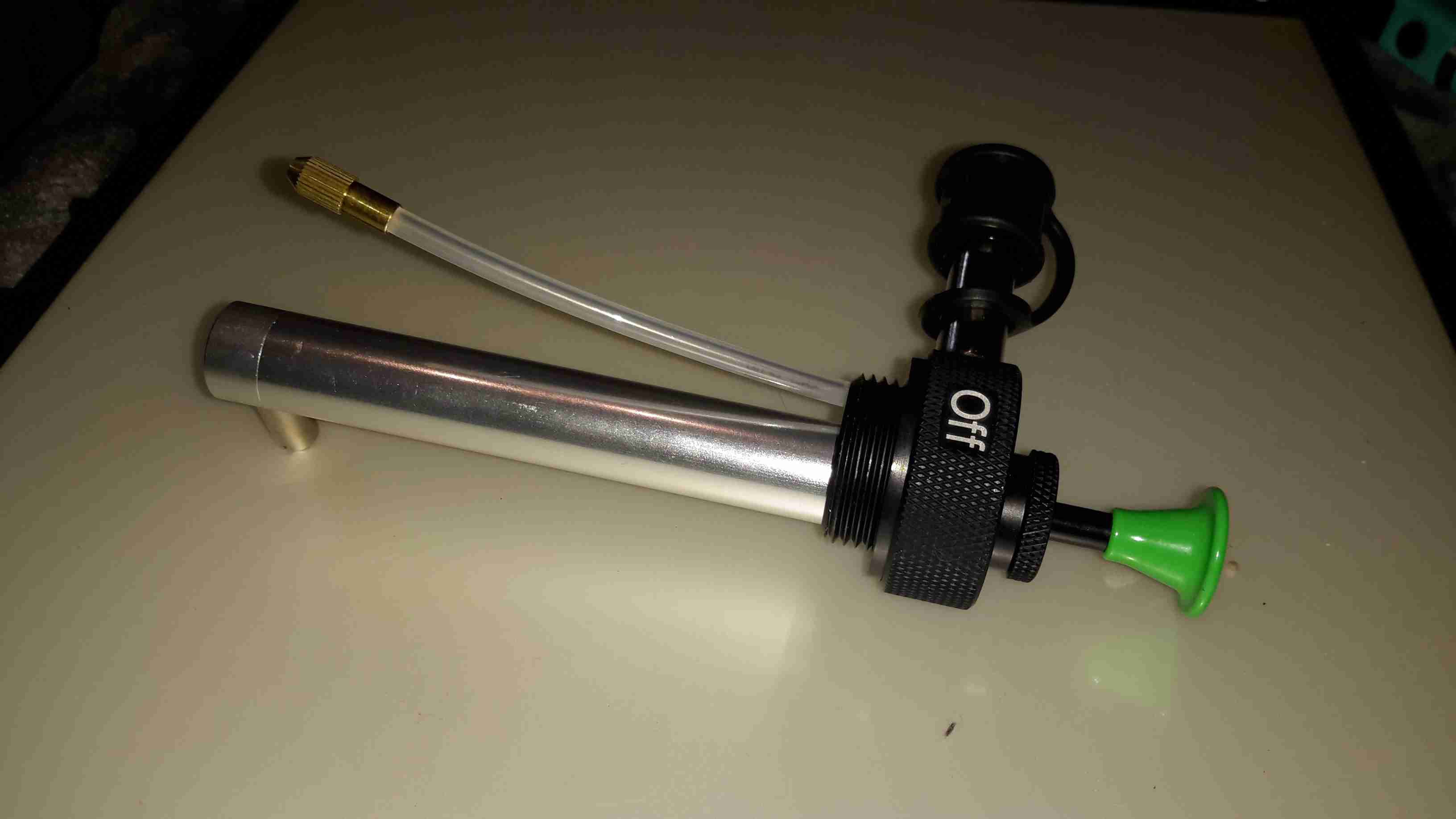
The method I use is heat based, using a Propane torch to destroy the epoxy package, without damaging the Silicon die too much.

TMS57002 Audio DSP
TMS57002 Audio DSP

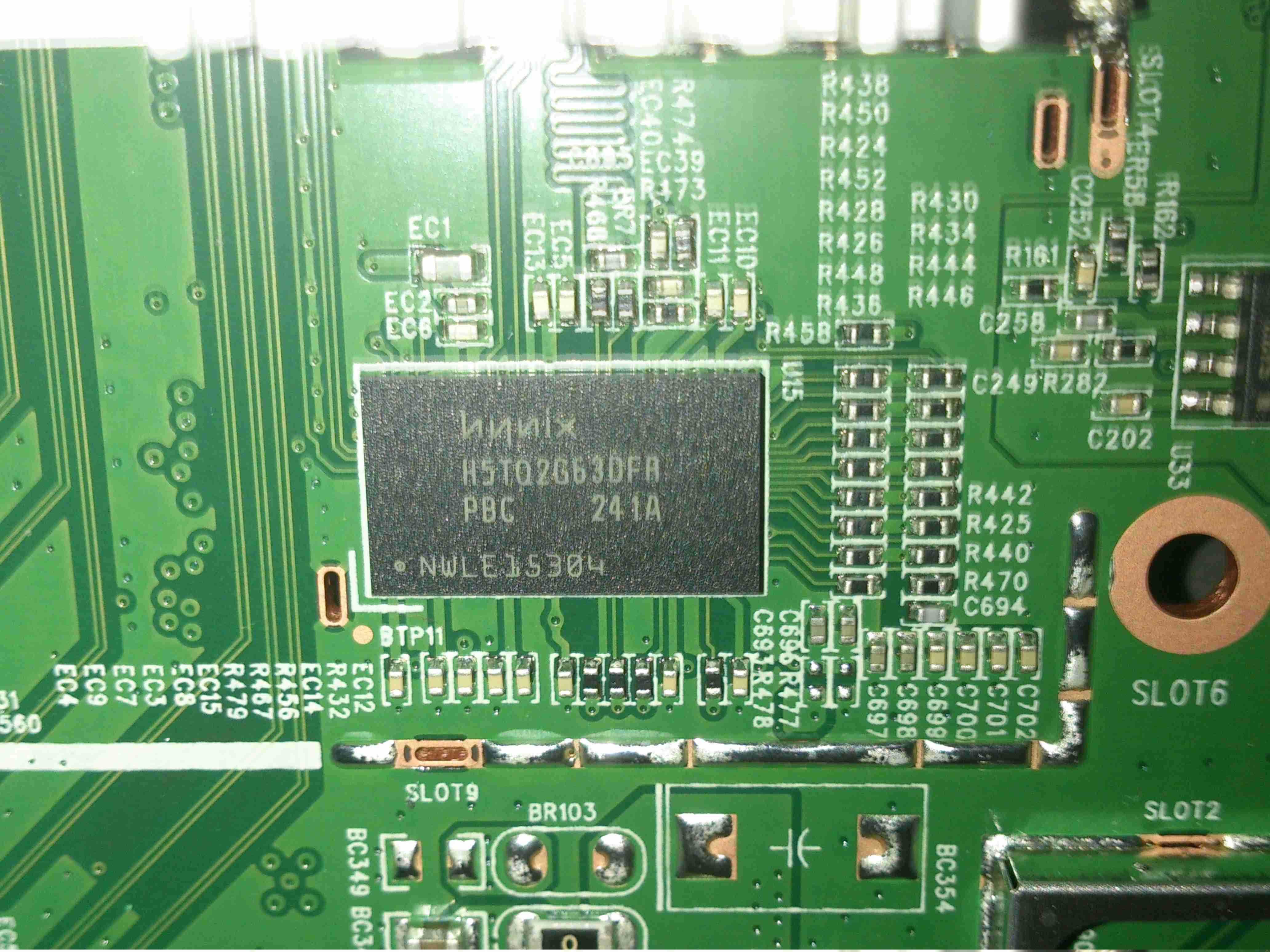
I start off, obviously, with a desoldered IC, the one above an old audio DSP from TI. I usually desolder en-masse for this with a heat gun, stripping the entire board in one go.

FLAMES!
FLAMES!

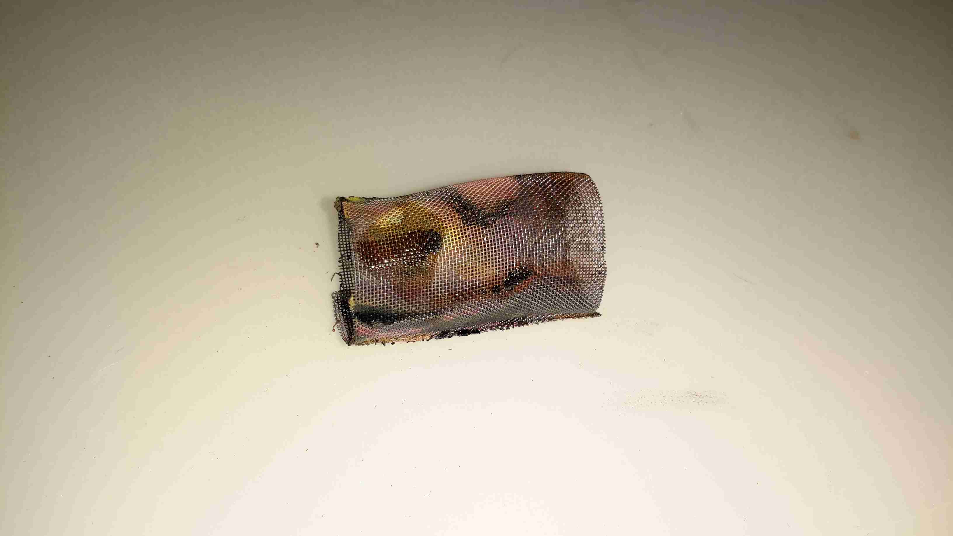
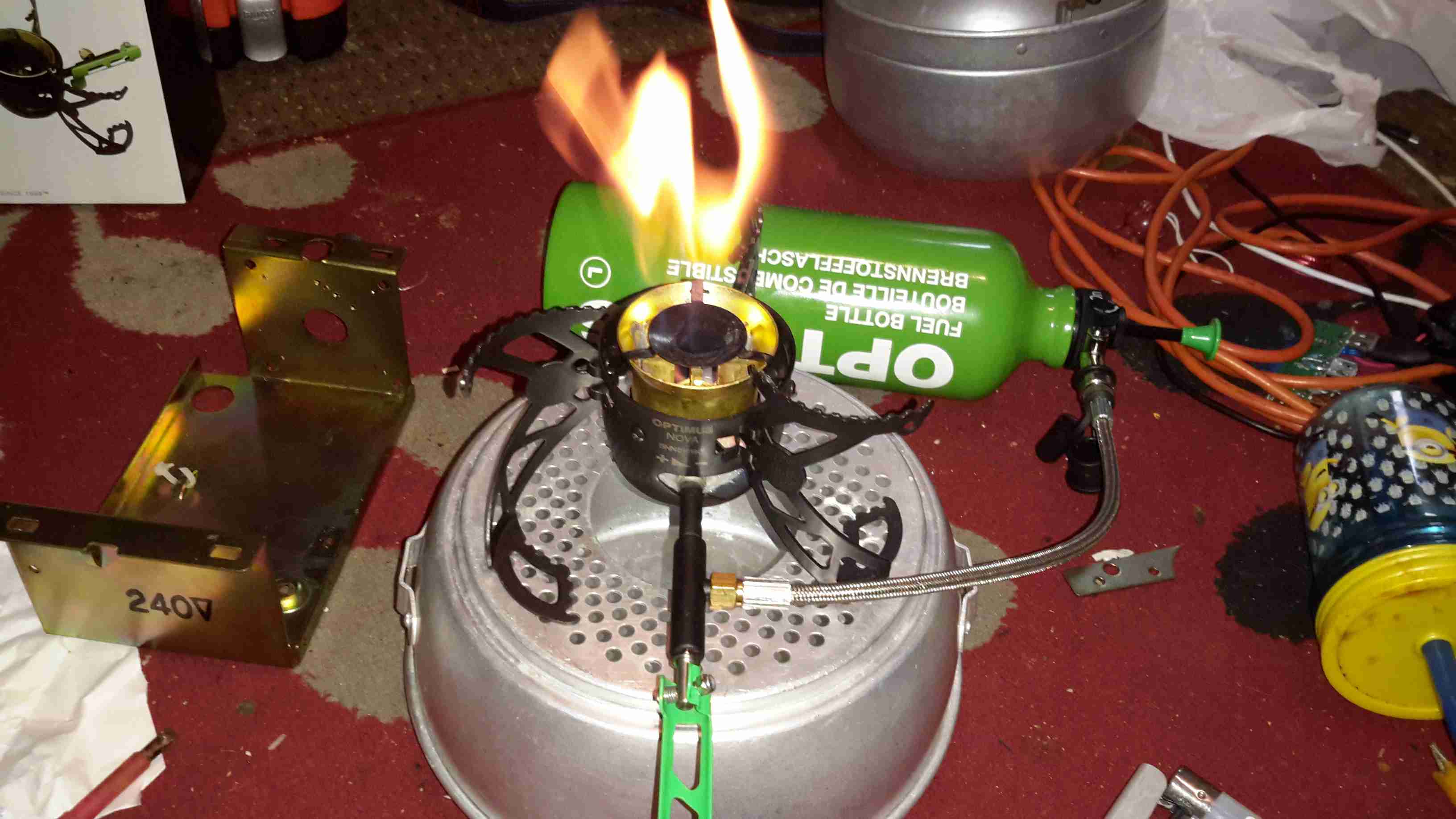
Next is to apply the torch to the IC. A bit of practice is required here to get the heat level & time exactly right, overheating will cause the die to oxidize & blacken or residual epoxy to stick to the surface.
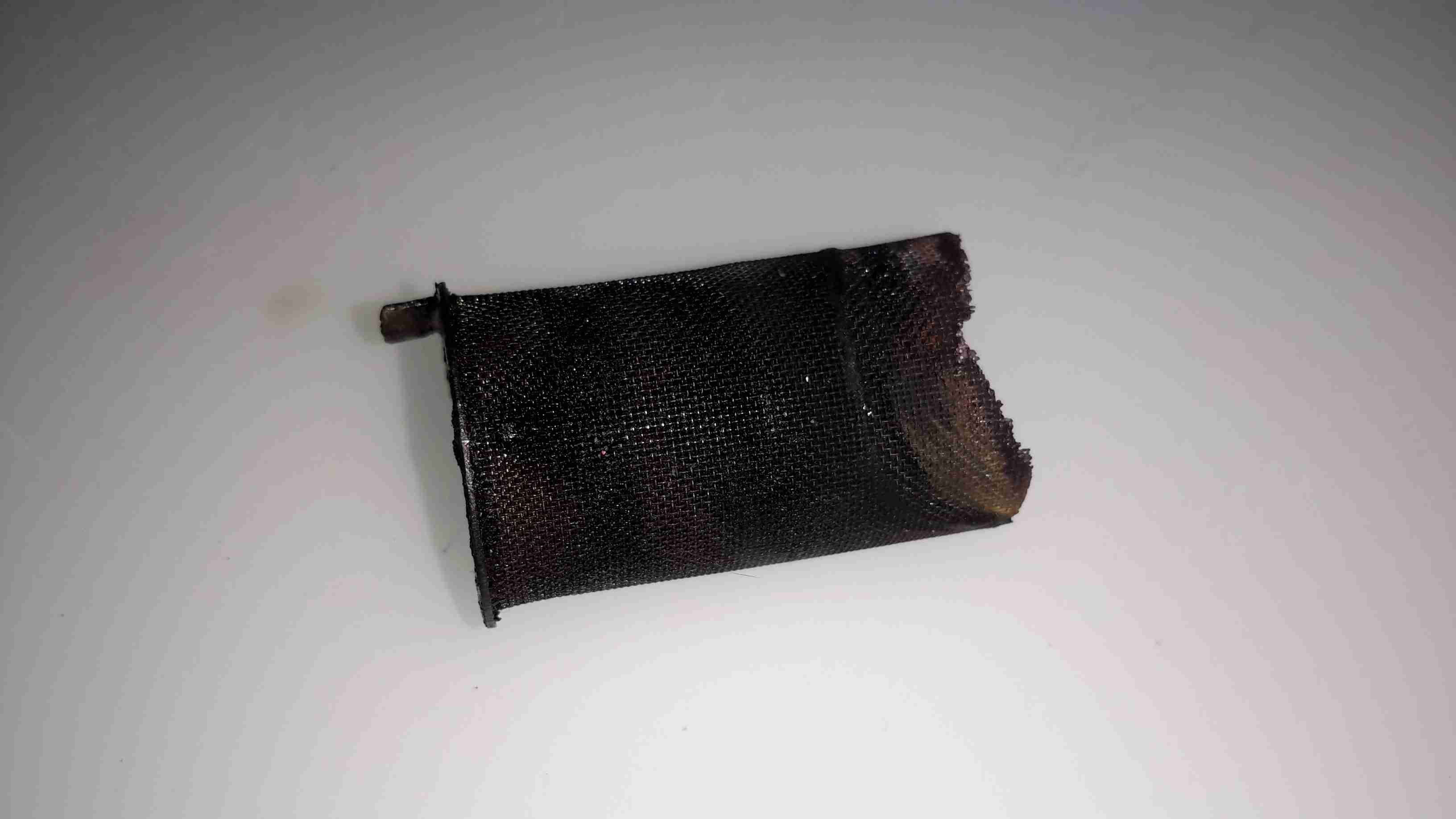
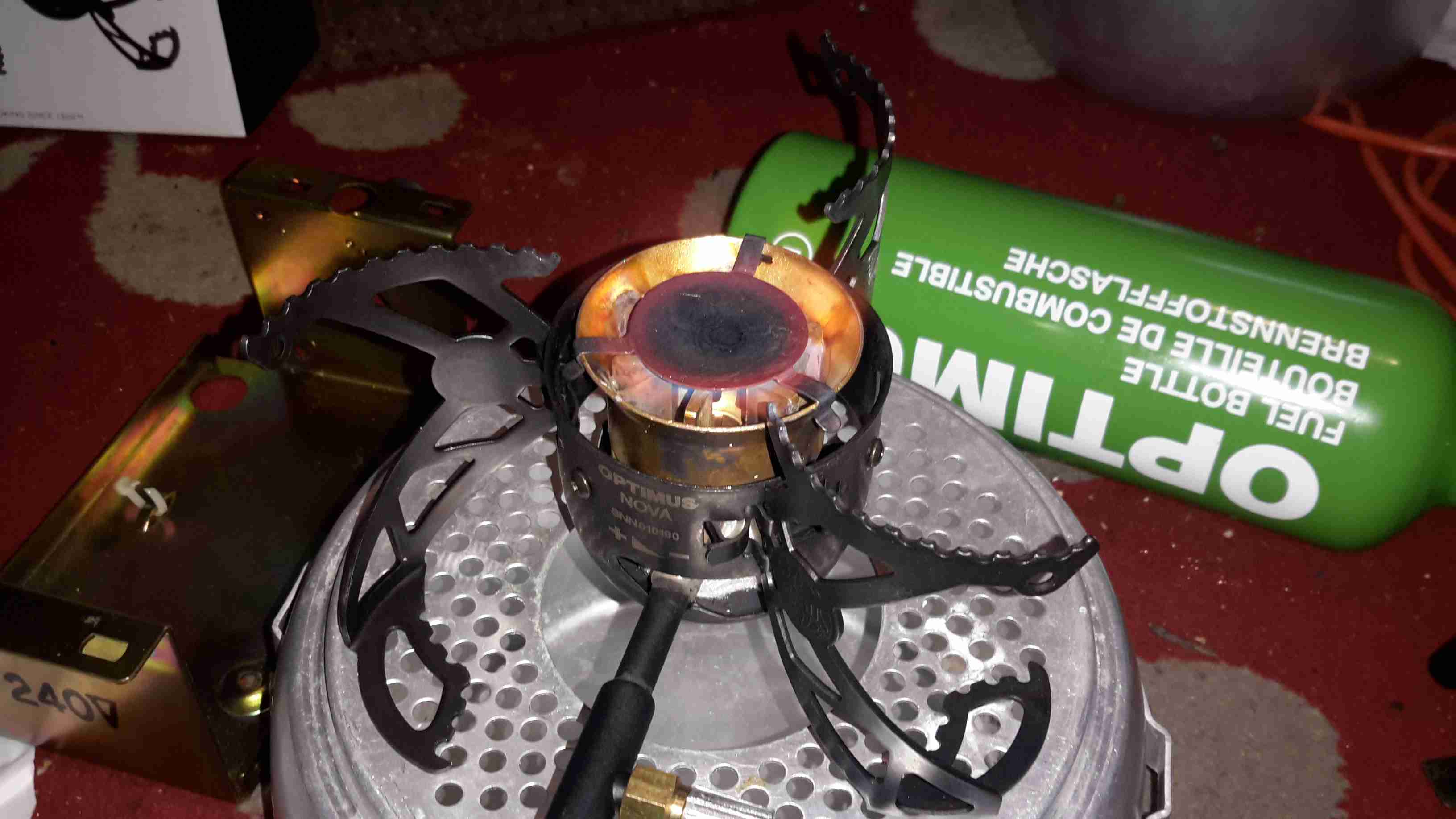
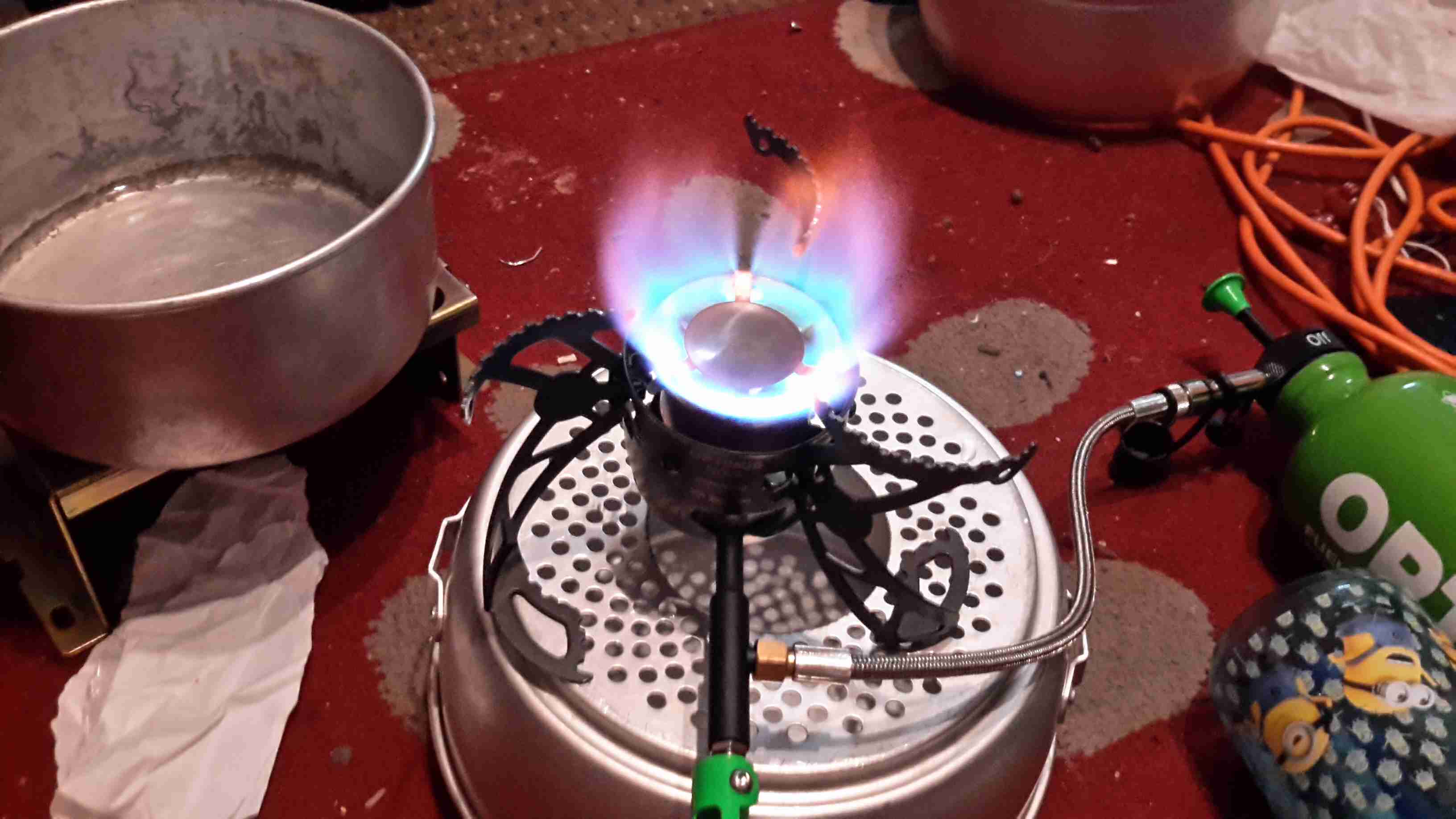
I usually apply the torch until the package just about stops emitting it’s own yellow flames, meaning the epoxy is almost completely burned away. I also keep the torch flame away from the centre of the IC, where the die is located.
Breathing the fumes from this process isn’t recommended, no doubt besides the obvious soot, the burning plastic will be emitting many compounds not brilliant for Human health!
Once the IC is roasted to taste, it’s quenched in cold water for a few seconds. Sometimes this causes such a high thermal shock that the leadframe cracks off the epoxy around the die perfectly.

All Your Die Belong To Us

Now that the epoxy has been destroyed, it breaks apart easily, and is picked away until I uncover the die itself. (It’s the silver bit in the middle of the left half). The heat from the torch usually destroys the Silver epoxy holding the die to the leadframe, and can be removed easily from the remaining package.

Decapped
Decapped

BGA packages are usually the easiest to decap, flip-chip packages are a total pain due to the solder balls being on the front side of the die, I haven’t managed to get a good result here yet, I’ll probably need to chemically remove the first layer of the die to get at the interesting bits 😉

Slide
Slide

Once the die has been rinsed in clean water & inspected, it’s mounted on a glass microscope slide with a small spot of Cyanoacrylate glue to make handling easier.

Some dies require some cleaning after decapping, for this I use 99% Isopropanol & 99% Acetone, on the end of a cotton bud. Any residual epoxy flakes or oxide stuck to the die can be relatively easily removed with a fingernail – turns out fingernails are hard enough to remove the contamination, but not hard enough to damage the die features.

Once cleaning is complete, the slide is marked with the die identification, and the photographing can begin.

Microscope Mods

I had bought a cheap eBay USB microscope to get started, as I can’t currently afford a proper metallurgical microscope, but I found the resolution of 640×480 very poor. Some modification was required!

Modified Microscope
Modified Microscope

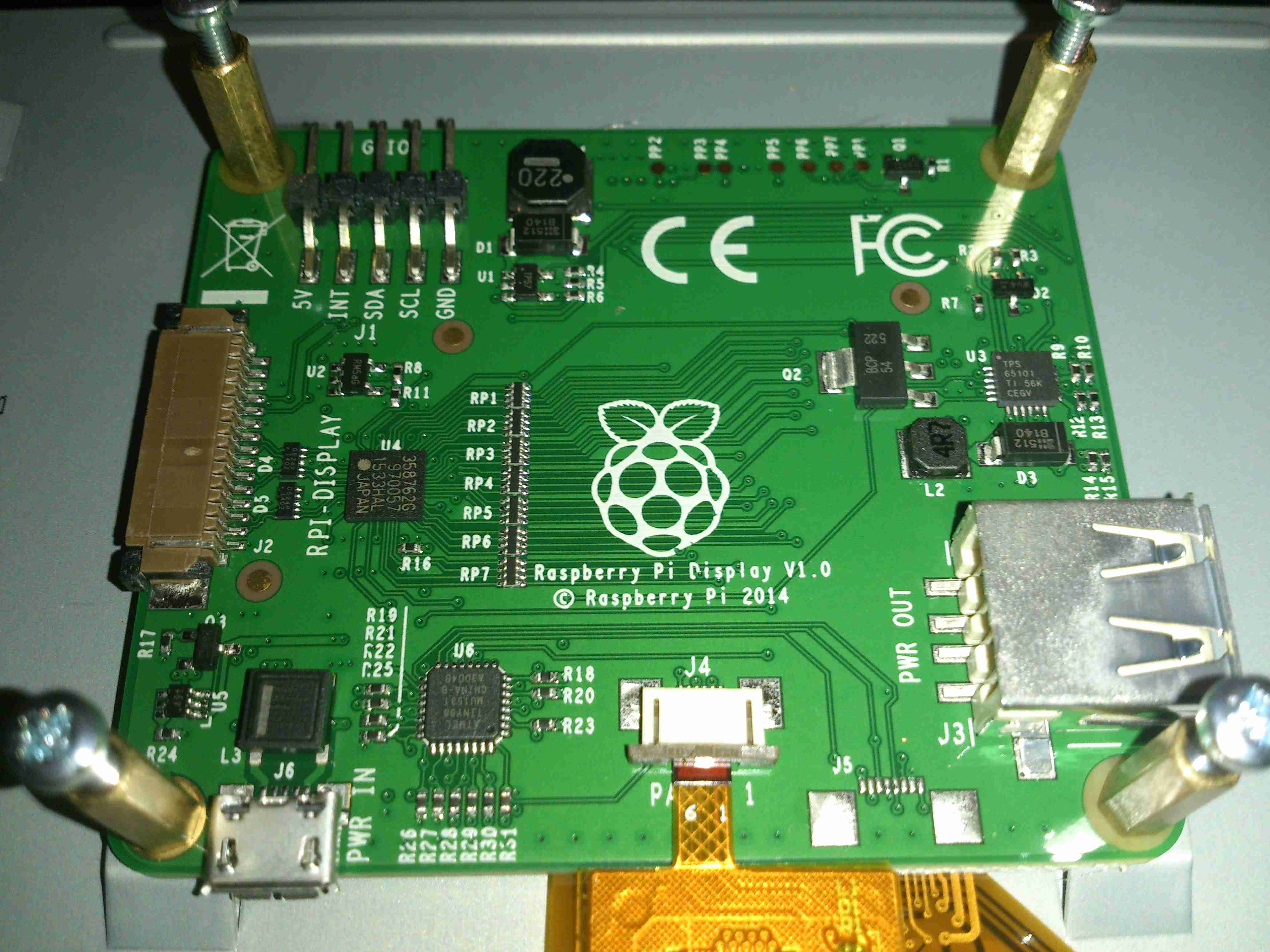
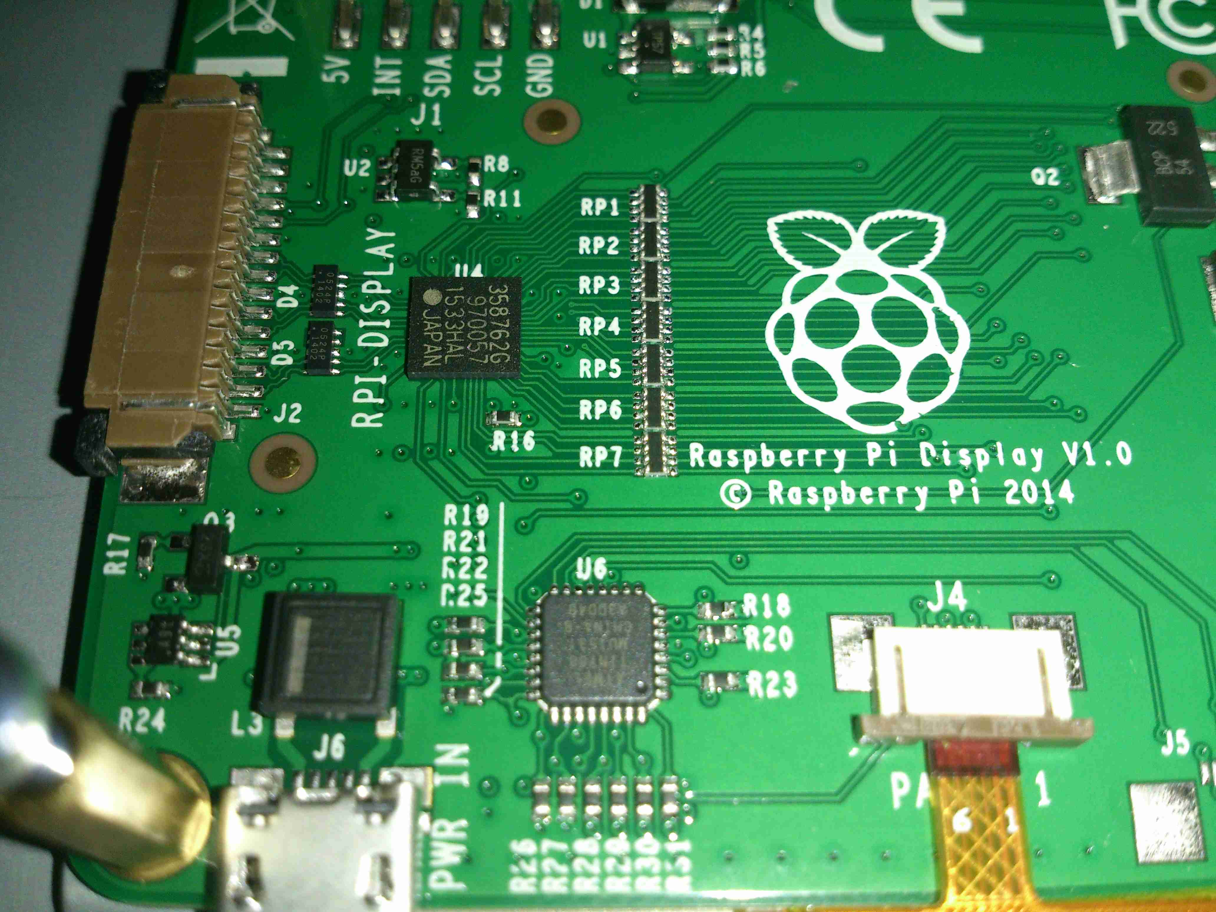
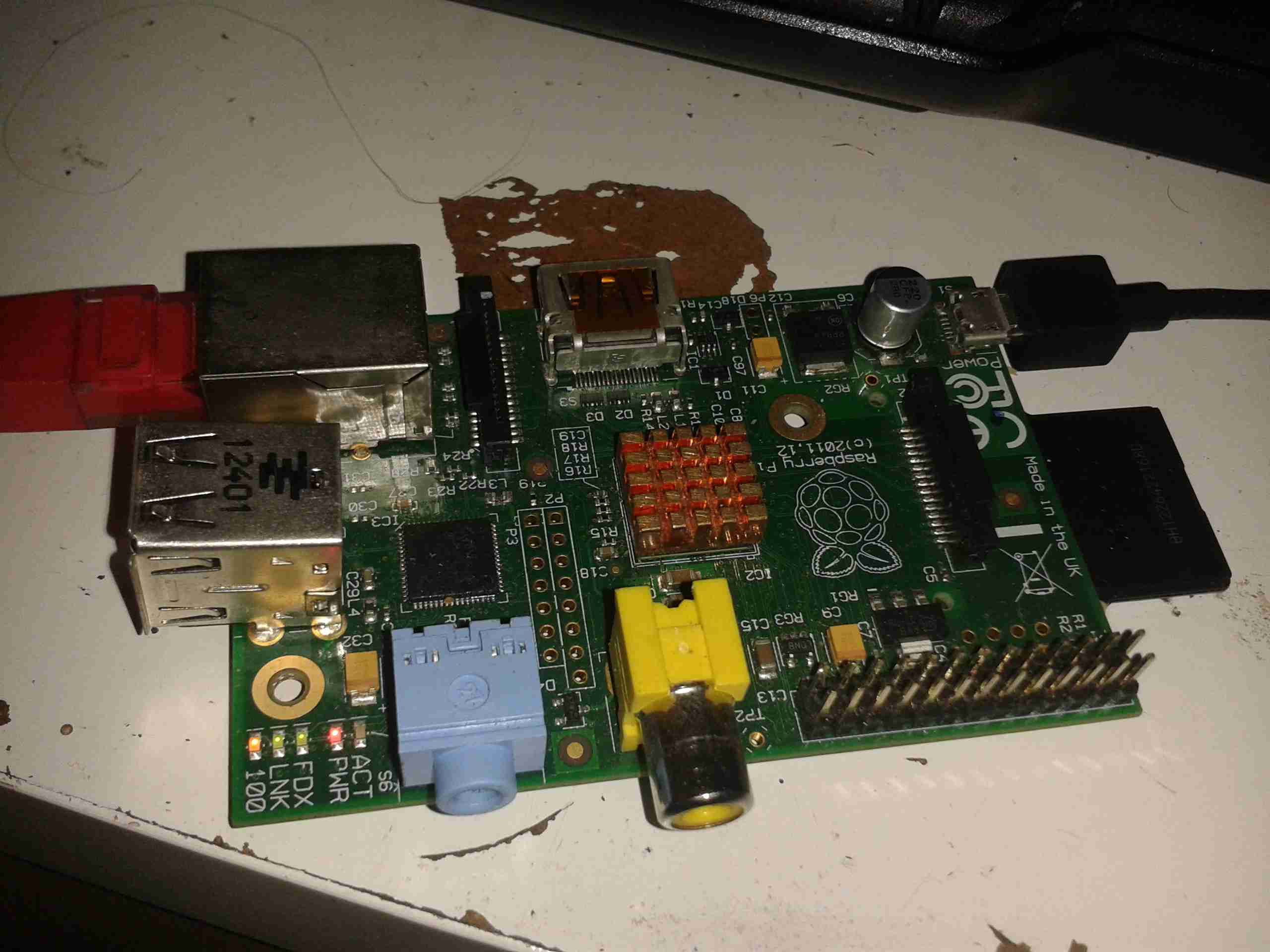
I’ve removed the original sensor board from the back of the optics assembly & attached a Raspberry Pi camera board. The ring that held the original sensor board has been cut down to a minimum, as the Pi camera PCB is slightly too big to fit inside.
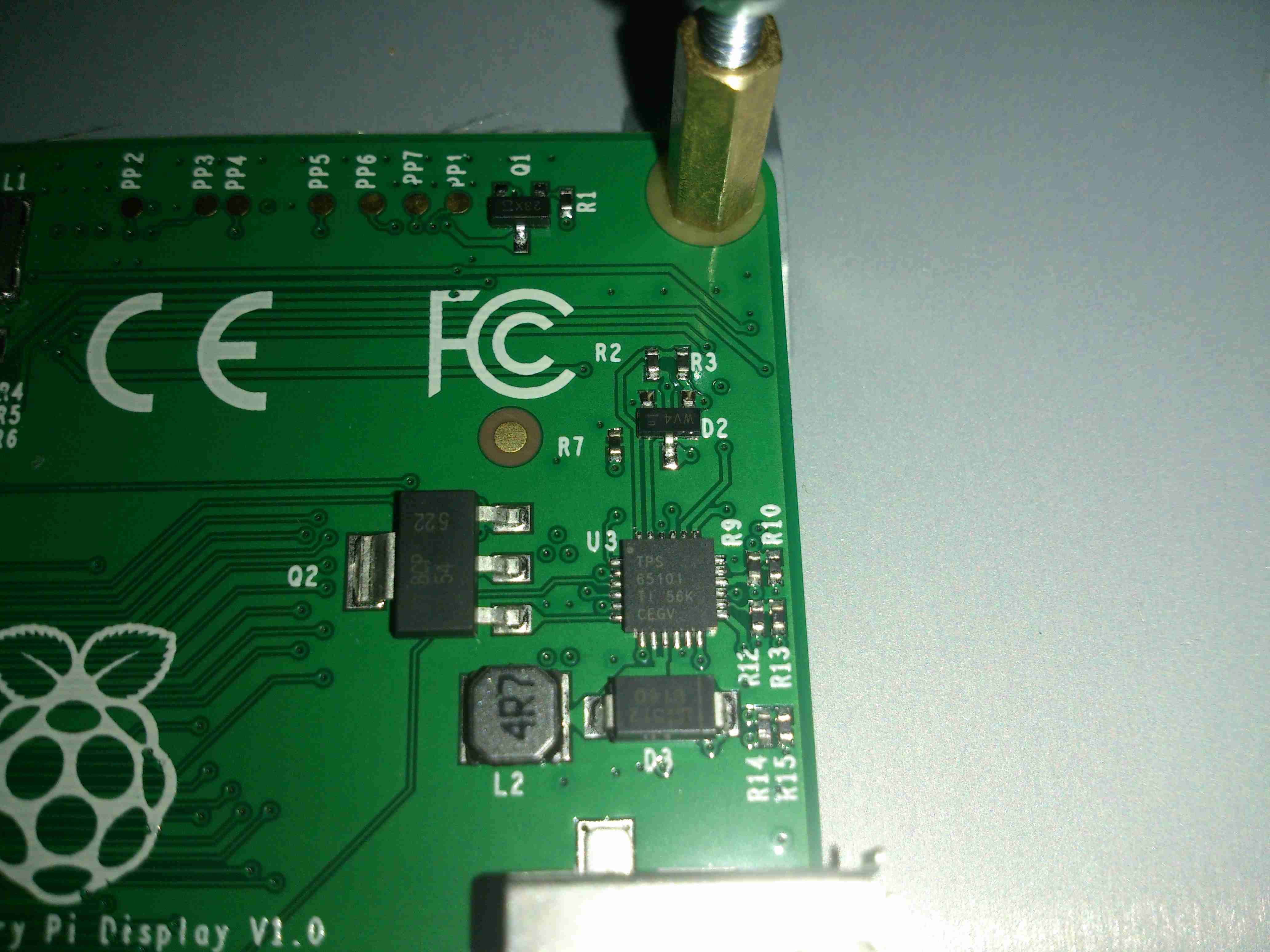
The stock ring of LEDs is run direct from the 3.3v power rail on the camera, through a 4.7Ω resistor, for ~80mA. I also added a 1000µF capacitor across the 3.3v supply to compensate a bit for the long cable – when a frame is captured the power draw of the camera increases & causes a bit of voltage drop.

The stock lens was removed from the Pi camera module by careful use of a razor blade – being too rough here *WILL* damage the sensor die or the gold bond wires, which are very close to the edge of the lens housing, so be gentle!

Mounting Base
Mounting Base

The existing mount for the microscope is pretty poor, so I’ve used a couple of surplus ceramic ring magnets as a better base, this also gives me the option of raising or lowering the base by adding or removing magnets.
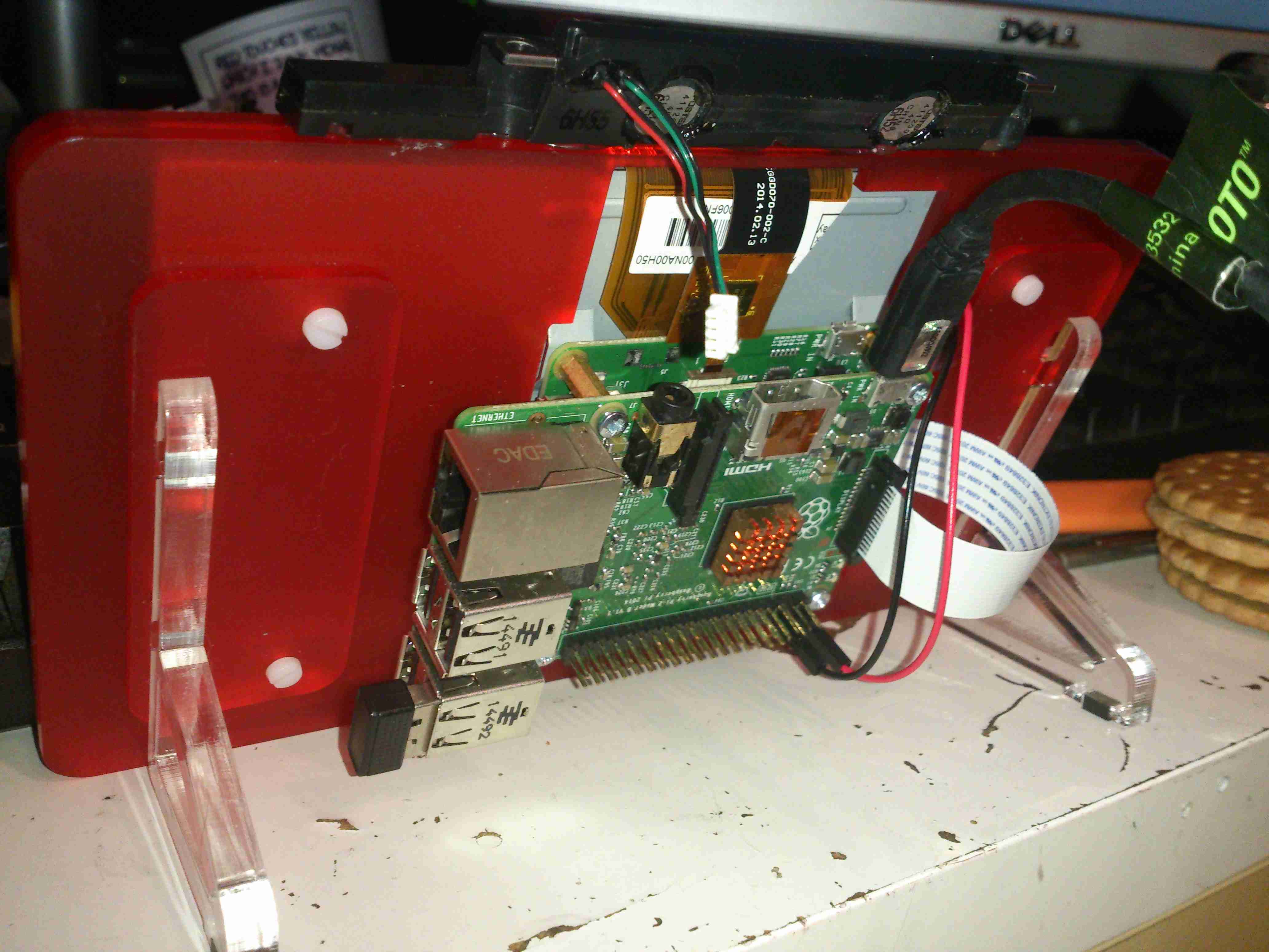
To get more length between the Pi & the camera, I bought a 1-meter cable extension kit from Pi-Cables over at eBay, cables this long *definitely* require shielding in my space, which is a pretty aggressive RF environment, or interference appears on the display. Not surprising considering the high data rates the cable carries.
The FFC interface is hot-glued to the back of the microscope mount for stability, for handheld use the FFC is pretty flexible & doesn’t apply any force to the scope.

Die Photography

Since I modified the scope with a Raspberry Pi camera module, everything is done through the Pi itself, and the raspistill command.

Pi LCD
Pi LCD

The command I’m currently using to capture the images is:
raspistill -ex auto -awb auto -mm matrix -br 62 -q 100 -vf -hf -f -t 0 -k -v -o CHIPNAME_%03d.jpg

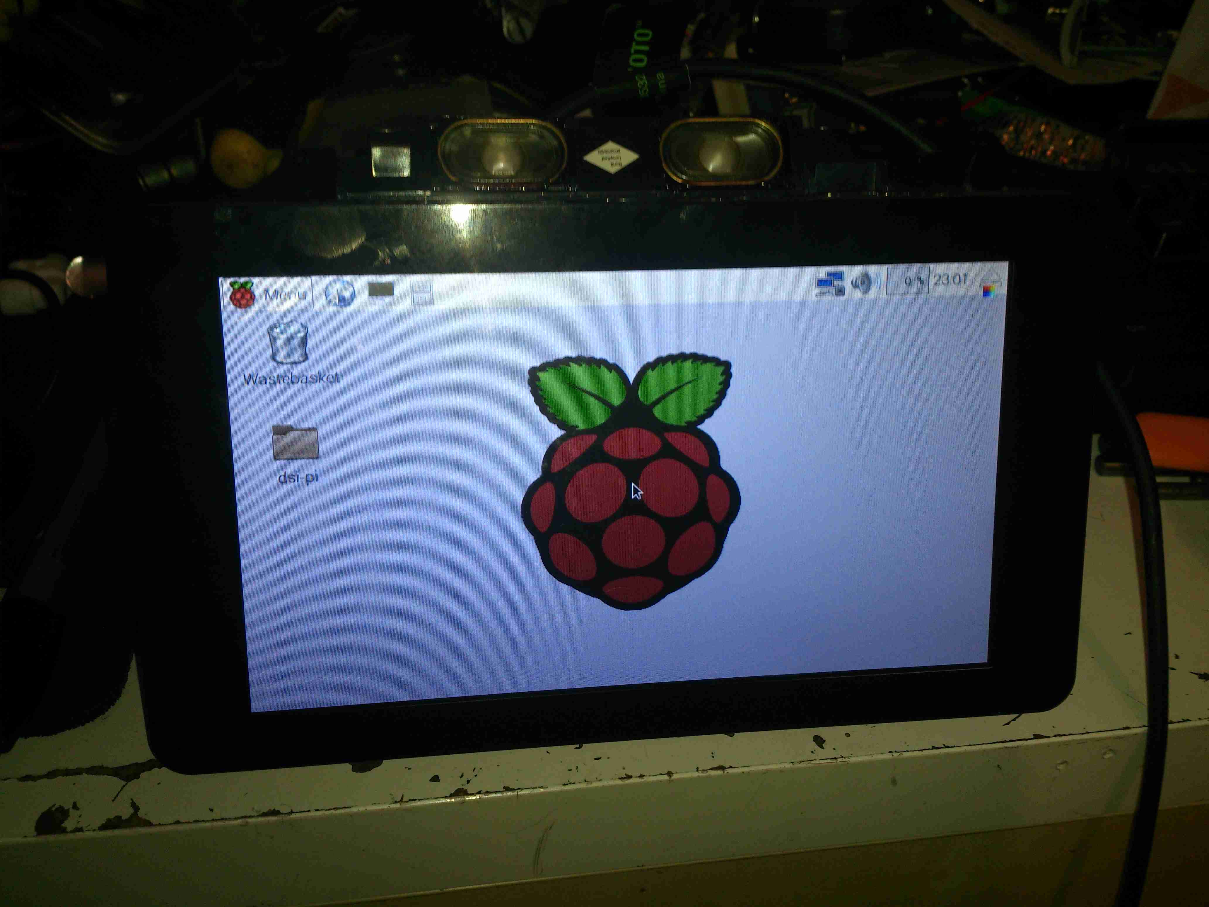
This command waits between each frame for the ENTER key to be pressed, allowing me to position the scope between shots. Pi control & file transfer is done via SSH, while I use the 7″ touch LCD as a viewfinder.

The direct overhead illumination provided by the stock ring of LEDs isn’t ideal for some die shots, so I’m planning on fitting some off-centre LEDs to improve the resulting images.

Image Processing

Obviously I can’t get an ultra-high resolution image with a single shot, due to the focal length, so I have to take many shots (30-180 per die), and stitch them together into a single image.
For this I use Hugin, an open-source panorama photo stitching package.

Hugin
Hugin

Here’s Hugin with the photos loaded in from the Raspberry Pi. To start with I use Hugin’s built in CPFind to process the images for control points. The trick with getting good control points is making sure the images have a high level of overlap, between 50-80%, this way the software doesn’t get confused & stick the images together incorrectly.

Optimiser
Optimiser

After the control points are generated, which for a large number of high resolution images can take some time, I run the optimiser with only Yaw & Pitch selected for all images.

Optimising
Optimising

If all goes well, the resulting optimisation will get the distance between control points to less than 0.3 pixels.

Panorama Preview
Panorama Preview

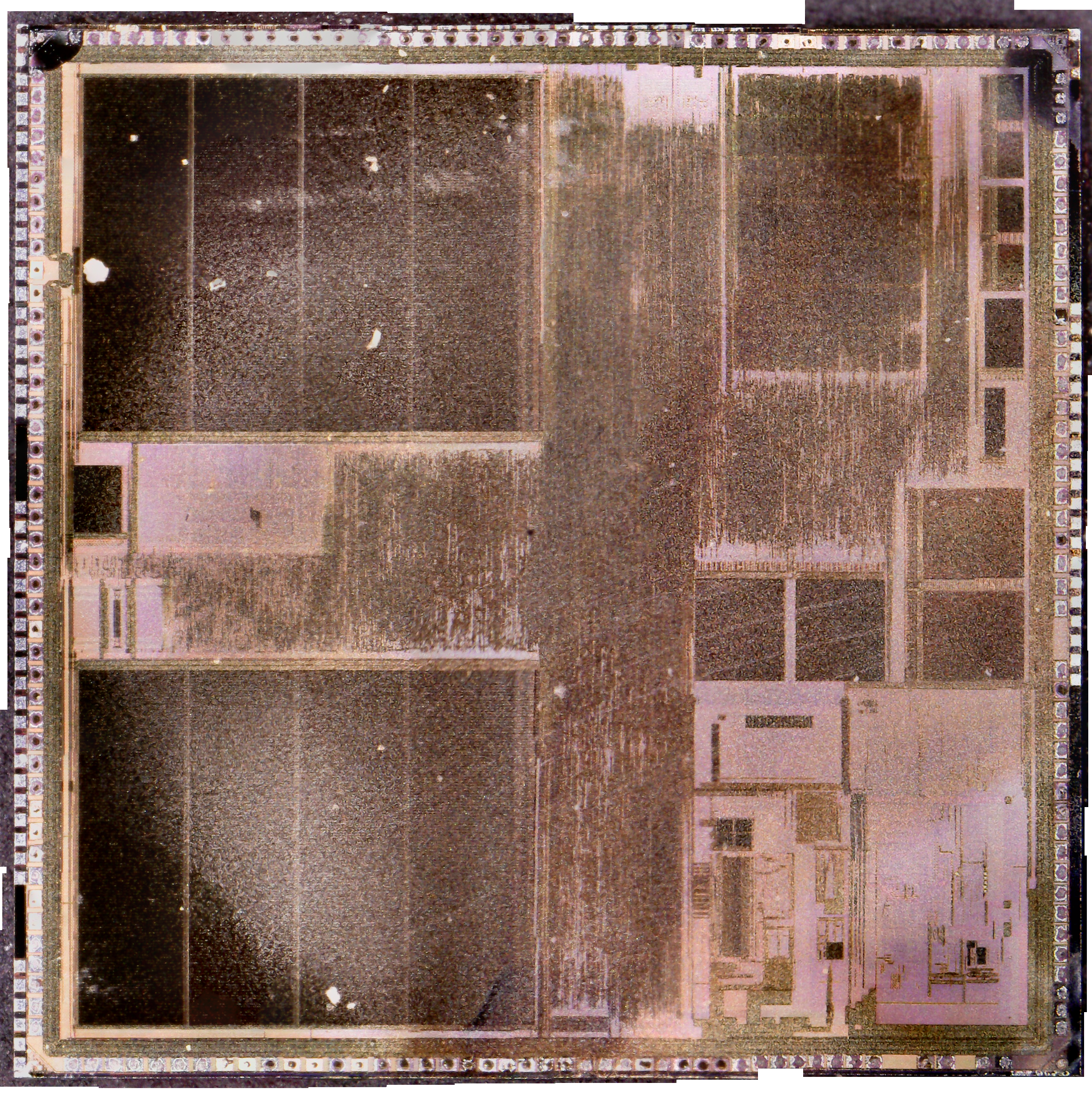
After the control points & optimisation is done, the resulting image can be previewed before generation.

Texas Instruments TMS67002

After all the image processing, the resulting die image should look something like the above, with no noticeable gaps.

Posted on Leave a comment

DIY Eberspacher Glowplug Screens

One of the central parts to the Eberspacher-type evaporative burner is the wire mesh screen that surrounds the glowplug, where the incoming fuel is heated to vapour before it’s blown into the combustion chamber & burned.
These screens, like glowplugs in the older heaters, are consumable parts and either get clogged with soot/tar or just eventually burn away.
The problem is that these parts (for what they are at least) are bloody expensive, so I’ve been looking to come up with something that can serve as a decent replacement for much lower cost.

OEM Screen
OEM Screen

Here’s a slightly used screen from my D1LCC heater, as can be seen the lower edge is already burning away even after only a few hours use. This edge tends to burn as the screen projects into the combustion chamber by about 1/4″, so it’s exposed to higher temperatures there. The rest of the screen is covered by the alloy casting that holds the burner. The mesh itself is stainless steel, and looks like something between 120-150 mesh.
The mesh is wound 2-3 turns, and spot welded to hold everything together. I would imagine to give more surface area for fuel vaporization. An unfortunate side effect of this is that the screen is much more susceptible to clogging as the mesh size is effectively reduced.

This also makes them damn near impossible to clean, as the carbon deposits get stuck between the layers in the screen. Applying a blowtorch flame to the entire screen & heating it to orange heat (~1200°C) does burn most of the crap out of them. Running Paraffin/Kerosene as the fuel also makes for a much cleaner burn, extending life.
(Assuming of course that the screen can be removed without totally destroying it – in my experience after many hours of running they seize in place & require sharp implements, violence & much swearing to remove, in several pieces.)

I had some copper mesh spare from a previous project, around the correct mesh size, so I figured I’d cut a piece to the same size as the official mesh & give it a go in the heater.

DIY Screen
DIY Screen

Here’s my single-layer DIY screen after a couple of hours operation in the heater. Ignition time doesn’t seem to be impaired, there’s no smoke from the exhaust, and it appears that it’s staying cleaner than an OEM screen, since the mesh size is a little larger. I’ll have to monitor the situation & see how long these last, but if it’s anything close to the OEM screen life it’ll make maintenance much cheaper.

Fuel Inlet
Fuel Inlet

This is the opening that holds the glowplug & it’s screen. The fuel inlet can be seen on the left wall of the chamber, with a circular groove that feeds fuel onto the screen in operation.

DIY Screen Fitted
DIY Screen Fitted

And here’s the DIY screen in place, it’s obviously not as good a fit as the OEM version, but it’s sufficient to do the job!

Glowplug
Glowplug

Finally, here’s the glowplug itself. Possibly the beefiest plug I’ve ever seen, even in large diesel engines.

Posted on Leave a comment

Camping Gear – Optimus Nova Multifuel Stove

Stove
Stove

For as long as I can remember I’ve been using Trangia-type alcohol fuelled stoves when I go camping, even though these have served my needs well they’re very limited & tend to waste fuel. I did some looking around for Paraffin/Kerosene fuelled stoves instead, as I already have this fuel on site.
I found very good reviews on the Optimus Nova above, so I decided to go for this one.

This stove can run on many different fuel types, “white gas” (petrol without any vehicle additives) Diesel, Kerosene & Jet A.

Burner
Burner

Here’s the “hot end” of the device, the burner itself. This is made in two cast Brass sections, that are brazed together. The fuel jet can be just seen in the centre of the casting.

Fuel Pump
Fuel Pump

The fuel bottle is pressurised with a pump very similar to the ones used on Paraffin pressure lamps, so I’m used to this kind of setup. The fuel dip tube has a filter on the end to stop any munge gumming up the valves or the burner jet.

Pre-Heating
Pre-Heating

As with all liquid-fuelled vapour burners, it has to be preheated. There’s a fibreglass pad in the bottom of the burner for this, and can be soaked with any fuel of choice. The manual states to preheat with the fuel in the bottle, but as I’m using Paraffin, this would be very smoky indeed, so here it’s being preheated with a bit of Isopropanol.
The fuel bottle can be seen in the background as well, connected to the burner with a flexible hose. The main burner control valve is attached to the green handle bottom centre.

Simmer
Simmer

Once the preheating flame has burned down, the fuel valve can be opened, here’s the stove burning Paraffin on very low simmer. (An advantage over the older alcohol burners I’m used to – adjustable heat!)

Full Power!
Full Power!

Opening the control valve a couple of turns gives flamethrower mode. At full power, the burner is a little loud, but no louder than my usual Paraffin pressure lamps.

Flame Pattern
Flame Pattern

With a pan of water on the stove, the flame covers the entire base of the pan. Good for heat transfer. This stove was able to boil 1L of water from cold in 5 minutes. A little longer than the manual states, but that’s still much quicker than I’m used to!

Fuel Jet
Fuel Jet

The top of the burner opens for cleaning, here’s a look at the jet in the centre of the burner. The preheating pad can be seen below the brass casting.

Posted on 4 Comments

Eberspacher Controller & Remote

7-Day Programmer
7-Day Programmer

The Eberspacher heaters can be controlled with a single switch, but it’s more convenient to have some temperature control & the option of a timer. Above is an ex-BT 701 series controller, with built in 7-day programmer. Being an ex-BT van version though, it’ll only switch the heater on for 1 hour at a time.
To get around this slight niggle, I fitted a bypass toggle switch.

Remote Control
Remote Control

For a bit of extra convenience, I got an RF remote controlled relay module from eBay (£5).
This allows me to switch things on remotely, so I can return to a nice toasty tent while camping.
There is an official RF remote for Eberspacher heaters, but I’ve no doubt they’re hideously expensive.

RF Receiver
RF Receiver

Here’s the receiver PCB, there’s an EEPROM & a microcontroller onboard for handling the codes the remotes send, but as the number has been scrubbed off the micro, no data there. This uses a standard RF receiver module.

RF Remote
RF Remote

Here’s the remote itself, this uses a 12v battery instead of a 3v lithium cell. A little of a pain since these batteries can be a bit pricey.
As this RF system operates on 315MHz, it’s technically illegal in the UK, but I was unable to find a 433MHz version with the features required. Nevermind ;).

Controller Internals

Here’s the module installed in the controller casing. I have since run the antenna wire around the edge of the case to try & get the furthest range on receive. The relay contacts are just paralleled across the bypass switch, so when the relay energizes the heater fires up.
Luckily the thermostatic control portion of the 701 programmer is operational even when heating mode is not active.

Posted on 6 Comments

Eberspacher Tent Heating System

The "Tenterspacher"
The “Tenterspacher”

I go camping on a regular basis here in the UK, and often even in summer it’s horribly cold at night in a field somewhere in the middle of Leicestershire. This doesn’t go too well with my severe aversion to being cold.
For the past several years I’ve used a Tilley lamp for some heat & light while at festivals & general camping, but it’s heat output is less than stellar when used in a 6-man tent.

An Eberspacher diesel heater was what was required for the job. Above is the unit as it’s built at the moment – I’ve used an old D1LCC 1.8kW heater that was recently decommissioned from nb Tanya Louise, as it’s getting a bit funny about what kind of fuel it’ll run on in it’s old age. It’ll work perfectly well on kerosene though – a fuel I already take with me camping for the Tilley.

It’s mounted on a base box, which is a repurposed steel electrical junction box that saw a previous life containing a 3-phase fan motor controller.

Data Plate
Data Plate

Here’s the info on the heater unit itself. Drawing 22W of power at 12v I’ll be getting 1.8kW of heat output – sounds good to me.


Box Internals
Box Internals

Here’s a view into the base box before the circulation fans were fitted, in early prototype stage. I used a small toroid as a clunk on the end of the rubber fuel line 😉

Support Components
Support Components

After a few bits from the Great eBay arrived, here’s the internals of the base unit at present. The fuel tank is a repurposed 2L fridge water container – made of tough HDPE so it’s fuel resistant.
The fuel pump is mounted on the left side next to the tank – having been wrapped in some foam to deaden the continual ticking noise it creates. The exhaust & it’s silencer are mounted at the rear, the silencer being retained by a surplus rubber shock mount. Luckily the exhaust systems on these heaters don’t get particularly hot, so the rubber doesn’t melt.
The exhaust outlet is routed through the frame, to be attached to an external hose. I don’t want combustion gases in the tent with me!

Standard Eberspacher silencers also aren’t gas-tight from the factory – they’re designed to be used in the open on the underframe of a vehicle, so I’ve covered all the seams in aluminium tape to make the system airtight.

Ventilation
Ventilation

To make sure that the support components don’t get overheated with the exhaust being in such close proximity, and to pull a little more heat out of the system, a pair of slow-running 80mm fans has been fitted to the end of the box. These blow enough air through to give a nice warm breeze from the vents on the other end of the base.

Fuel Tank
Fuel Tank

The tank I’ve used just so happened to be the perfect size to fit into the base box, and to tap the fuel off a bulkhead fitting was put into the top of the tank, with a dip tube on the other side. The fuel line itself is tiny – only 4mm.
If the specifications from Eberspacher are to be believed, 2L of fuel on board will allow the system to run for about 8 hours on full power, or 16 hours on minimum power.

Being inside the base, refuelling is a little awkward at the moment, the heater has to completely cool before the exhaust can be detached without receiving a burn, so I’ll be building in a fuel transfer system from an external jerry can later to automate the process – this will also help to avoid messy fuel spills.

More to come when the rest of the system is worked out!

73s for now!

Posted on Leave a comment

eBay Mini Gear Pump Teardown

Mini Pump
Mini Pump

I got one of these to test since I’ve been in need of some small DC pumps for fluid transfer use. At £2 I can definitely afford to experiment.

DC Motor
DC Motor

On the eBay listing, these pumps are rated at 3-12v DC, (I thought that was a bit wide of an operating range), I looked up the motor, an RS-360SH on Mabuchi’s website, they only have models in this range rated at 7.2v & 24v. Judging by the size of the windings on the armature & the fact that after a few minutes operation on 12v it gets rather hot, I’m going to say this is the 7.2v motor.

Pump Gears
Pump Gears

Removing the screws releases the end cover & the pair of gears inside. This operates like any other hydraulic gear motor, albeit with much wider tolerances. It has no capability to hold pressure when the power is removed, and can be blown through easily.
Flow & pressure under power are quite good for the pump’s size, even though it’s noisy as hell.

Posted on Leave a comment

Duratool ZD-915 12v Conversion

Inkeeping with everything else in my shack being low voltage operated, I had planned from the outset to convert the desoldering station to 12v operation. It turns out this has been the easiest tool to convert in my shack so far.

PSU Outputs
PSU Outputs

The factory SMPS is a fairly straightforward 18v 12A unit, with only a single small oddity: the desoldering gun’s heating element is controlled from inside the supply.

Iron MOSFET
Iron MOSFET

Next to the output rectifier on the heatsink is a large MOSFET, in this case a STP60NF06 from ST Micro. This is a fairly beefy FET at 60v & 60A capacity, RDS On of <0.016Ω.
This is driven via an opto-isolator from the main logic board. I’ve not yet looked at the waveform on the scope, but I suspect this is also being PWM’d to control temperature better when close to the set point.

Iron Element Controller

Rather than fire up the soldering iron & build a new element controller circuit (Lazy Mode™), I opted to take a saw to the original power supply. I cut the DC output section of the PCB off the rest of the supply & attached this piece back to the frame of the base unit. I also added a small heatsink to the MOSFET to make sure it stays cool.

12v Power Supply
12v Power Supply

Since the fan & vacuum pump are both already 12v rated, those are connected directly to the DC input socket, that I’ve installed in place of the original IEC mains socket. The 18v for the heating element is generated by a 10A DC-DC converter, again from eBay.

Oddly, the iron itself is rated at 24v 80W, but the factory supply is only rated to 18v. I’m not sure why they’ve derated the system, but as the station already draws up to 10A from a 13.8v supply, increasing the voltage any further would start giving my DC supplies a problem, so it can stay at 18v for now.

Posted on Leave a comment

ViewSonic VA2232W-LED Monitor 12v Conversion

ID Label
ID Label

On the quest to get things on board replaced that are heavy users of power, the monitor in the main cabin was next. The original CCFL-backlit monitor was very heavy on 12v power, at 5A. This meant falling asleep watching TV would result in severely flattened batteries.

Replacement with a suitable LED-backlit monitor was definitely required. The cheapest on eBay was a ViewSonic VA2232W-LED, so I took to work converting it from 240v to 12v operation.

Back Cover Removed
Back Cover Removed

There are no screws holding these monitors together, so a spudger & frequent swearing got the back off. The shield holding the circuitry is also not screwed down, only attached to the back of the LCD panel with aluminium shielding tape.

Power PCB Trackside
Power PCB Trackside

Once the tape has been cut, the main power board is accessible. The large IC on the left is the main backlight LED driver.

In this case the monitor requires a pair of rails from the supply, 18.5v for the backlight circuitry & 5v for the logic.

DC-DC Regulators
DC-DC Regulators

A pair of DC-DC converters has been fitted in the small space between the power & control boards.

PCB Connection Points

To save me some work & keep maximum compatibility, I’ve not modified the existing supply, just attached the new DC-DC converter outputs onto the corresponding outputs of the factory PSU. The 12v input leads are routed out of the same gap as the mains IEC connector, with some hot glue over the mains input solder points to provide some more insulation.

Wiring Tidied
Wiring Tidied

The wiring is tidied up with hot glue so the back cover will go back on.

Total current draw at 12v is 1.4A.

Posted on Leave a comment

Cheap Lithium Polymer Battery Packs

In the past, I’ve used RC type LiPo packs for my mobile power requirements, but these tend to be a bit bulky, since they’re designed for very high discharge current capability – powering large motors in models is a heavy job.

I recently came across some Samsung Galaxy Tab 10.1 battery packs on eBay very cheaply, at £2.95 a piece. For this price I get 6800mAh of capacity at 4.2v, for my 12v requirements, 3 packs must be connected in series, for a total output of 12.6v fully charged.

For an initial pack, I got 9 of these units, to be connected in 3 sets of 3 to make 20Ah total capacity.There are no control electronics built into these batteries – it’s simply a pair of 3400mAh cells connected in parallel through internal polyfuses, and an ID EEPROM for the Tab to identify the battery.
This means I can just bring the cell connections together with the original PCB, without having to mess with the welded cell tabs.

Battery Pack
Battery Pack

Here’s the pack with it’s cell connections finished & a lithium BCM connected. This chemistry requires close control of voltages to remain stable, and with a pack this large, a thermal runaway would be catastrophic.

Cell Links
Cell Links

The OEM battery connector has been removed, and my series-parallel cell connections are soldered on, with extra lead-outs for balancing the pack. This was the most time-consuming part of the build.

If all goes well with the life of this pack for utility use, I’ll be building another 5 of these, for a total capacity of 120Ah. This will be extremely useful for portable use, as the weight is about half that of an equivalent lead-acid.

Posted on Leave a comment

LB-Link USB Wireless-N Adaptor Teardown

I needed a decent WiFi adaptor for my latest Pi LCD project, so after trawling eBay for cheapy USB adaptors, I found this one.

USB WiFi Dongle
USB WiFi Dongle

Unlike most USB WiFi radios these days, it actually has a proper RP-SMA antenna connector, not the low-gain built in jobbies that never seem to work too well.
There are a few versions of this adaptor, all of which seem to use the same casing, there’s a button push cut into the plastic for a WPS button that doesn’t exist on this model. This is fine, as I don’t enable WPS on any of my network equipment anyway. (It’s insecure, and can be cracked in minutes).

MAC Address
MAC Address

Here’s the rest of the essential details, the model is BL-LW08-AR, rated at 300Mbit/s.

PCB Reverse
PCB Reverse

Here’s the PCB removed from the casing, there are a pair of PCB antennas on here, but they’re not connected to the RF circuitry in this model, the links are missing.

Chipset
Chipset

The chipset used is a Realtek RTL8191SU, there isn’t much more in this device, as it’s all built into the silicon.


Posted on Leave a comment

nb Tanya Louise – Compressor Install

Compressed air is a rather useful power source, especially when all maintenance is done by the on board crew instead of by boatyards.

Screwfix had a good deal on a 50L 3.5CFM air compressor, to save space this has been permanently mounted in a free space & air will be piped to where it is needed from a central point.

Because of the total height of the machine, the compressor itself has been unbolted from the tank, a copper line connecting the two back together at a larger distance.

Bearers
Bearers

In one of the very few free spaces available, under a bunk. A pair of timbers has been screwed to the floor to support the tank.

Tank Installed
Tank Installed

The tank is strapped to the wooden supports with a pair of ratchet straps, the compressor itself can be seen just behind the tank. The copper line on the top of the tank is going back to be connected to the compressor outlet.

Air Fittings
Air Fittings

Compressor control remains on top of the tank, the pressure switch & relief valve centre. After an isolation valve, the feed splits, the regulator installed will be feeding the air horn with 20PSI, replacing the existing automotive-style 12v air pump. The currently open fitting will be routed to a quick connect on the bulkhead. This will be accessible from the front deck, an air hose can be fitted to get a supply anywhere on board.

More to come when the rest of the system gets installed!

73s for now.

Posted on Leave a comment

Official Raspberry Pi 7″ Touch LCD

Raspberry Pi LCD
Raspberry Pi LCD

Finally the Raspberry Pi Foundation have released an official LCD for the DSI connector on the Pi. When these were announced, I placed an order straight away, but due to demand it’s taken quite a while for it to arrive in the post.

Interface PCB
Interface PCB

The LCD itself is an RGB panel, to interface the Pi via the MIPI DSI port, some signal conversion is required. A small PCB is mounted on the back of the LCD to do this conversion. It also handles the power supply rails required by the LCD itself & interfacing the touch screen.

LCD Power Supply
LCD Power Supply

Taking care of the power supply is a Texas Instruments TPS65101 triple output LCD power supply IC. This also has a built in linear regulator to supply 3.3v for the rest of the circuitry on board. The large transistor to the left of the IC is the pass transistor for this regulator.

Main Controller
Main Controller

The video signal comes in on the FFC connector on the left, into the BGA IC. I’ve not managed to identify this component, but it’s doing the conversion from serial video from the Pi to parallel RGB for the LCD.
There’s also an Atmel ATtiny88 on the board below the main video conversion IC, not sure what this is doing.
The touch controller itself is mounted on the flex of the LCD, in this case it’s a FT5406.

Raspberry Pi LCD
Raspberry Pi LCD

Here’s the LCD in operation. It’s not the highest resolution out there, but it leaves the GPIO & HDMI ports free for other uses.

Pi Mounted
Pi Mounted

The Pi screws to the back of the LCD & is connected with a flat flex cable & a pair of power jumpers. I’ve added a couple of small speakers to the top edge of the LCD to provide sound. (More to come on this bit).


Posted on Leave a comment

Quickie Project: Ruggedising The RTL-SDR Dongle

As supplied, the RTL type tuner dongles are a little fragile, especially when they’ve got a rather heavy coax feeder attached for Ham Radio use.

The MCX antenna connectors on the tuner can’t stand up to much abuse, and even the USB plug rips itself from it’s mounts after a while with a heavy weight on the end. Since this dongle sits in my radio go bag, it definitely needed some protection & support.

PCB
PCB

The PCB itself is removed from it’s flimsy plastic casing, the USB plug is desoldered from the board.
To the exposed pads, a USB cable is soldered, giving much more flexibility in where the tuner is placed.
Instead of using the MCX antenna connector on the PCB, the coax is stripped & soldered direct to the PCB itself, as this connector has become unreliable.

N-Connector
N-Connector

To get the RF into the device, the case is fitted with an N connector, as is everything else in my shack.

Boxed
Boxed

The box used is a surplus one which previously housed an electronic lighting transformer. This would be very easy to waterproof as well, for more protection against outdoor use.

Posted on 2 Comments

Cisco EA6700 / Linksys AC1750 Router

Cisco EA6700
Cisco EA6700

Since the boat was still running it’s internal network on 10/100M speeds, an upgrade was decided on, the internal WiFi signal strength was also pretty poor further than a few feet from the NOC.

The new router is a Cisco/Linksys AC1750 model, with gigabit networking, and full 802.11ac 2.4/5GHz Wireless. This router also has a built in media server, print server, USB3 & USB2.

PCB Overview
PCB Overview

Teardown time! Here’s the router with the cover removed. Most of the fun stuff is hidden under the shields, but these aren’t fully soldered down & the covers are removable. The 6 antennas can be seen spaced around the edge of the housing, the main CPU is under the large heatsink upper centre. The radio power amplifier stages are underneath the shields, while the main RF transceivers are just outside the shields.

2.4GHz Transceiver
2.4GHz Transceiver

Wireless N is provided by a Broadcom BCM4331, this provides full dual-band 3×3 802.11n support. Being 3×3 it is actually 3 separate transceivers in a single package, to get much higher throughput rates of 600Mbit/s.

5GHz Transceiver
5GHz Transceiver

Wireless AC is provided by it’s sister IC, the BCM4360, with throughput speeds of 1.3Gbit/s. Both of these transceiver ICs connect back to the main CPU via PCI Express.

5GHz Power Amplifiers

To get increased range, there are a trio of Skyworks SE5003L +23dBm 5GHz power amplifier ICs under the shield, along with the TX/RX switching & antenna matching networks. Heatsinking for these is provided by a sink screwed to the bottom side of the PCB. The outputs to the antennas can be seen at the top of the image.

2.4GHz Power Amplifiers

The 2.4GHz section is fitted with a trio of Skyworks SE2605L +23dBm 2.4GHz power amplifiers, with a similar heatsink arrangement under the board. Unlike the 5GHz section, the 2.4GHz antenna feeds are soldered to the PCB here instead of using connectors.

Main CPU
Main CPU

The main CPU is a BCM4708 Communications Processor from Broadcom, as for the other Broadcom chips in this router, very little information is available unless under NDA, but I do know it’s a dual core ARM Cortex A9 running at 1GHz, with built in 5-port gigabit ethernet switch.

CPU RAM
CPU RAM

Working RAM for the processor is a Hynix H5TQ2G63DFA 256MB part.

More to come on the installation of the new networking, with it’s associated 4G mobile gateway connection system.

73s for now!

Posted on Leave a comment

Maplin/Refrakta Torch Modification & Mode Removal

The multimode dimming/flashing modes on Chinese torches have irritated me for a while. If I buy a torch, it’s to illuminate something I’m doing, not to test if people around me have photosensitive epilepsy.

Looking at the PCB in the LED module of the torch, a couple of components are evident:

LED Driver PCB
LED Driver PCB

There’s not much to this driver, it’s simply resistive for LED protection (the 4 resistors in a row at the bottom of the board).
The components at the top are the multimode circuitry. The SOT-23 IC on the left is a CX2809 LED Driver, with several modes. The SOT-23 on the right is a MOSFET, for switching the actual LED itself. I couldn’t find a datasheet for the IC itself, but I did find a schematic that seems to match up with what’s on the board.

Schematic
Schematic

Here’s that schematic, the only thing that needs to be done to convert the torch to single mode ON/OFF at full brightness, is to bridge out that FET.

Components Desoldered

To help save the extra few mA the IC & associated circuitry will draw from the battery, I have removed all of the components involved in the multimode control. This leaves just the current limiting resistors for the LED itself.

Jumper Link
Jumper Link

The final part above, is to install a small link across the Drain & Source pads of the FET. Now the switch controls the LED directly with no silly electronics in between. A proper torch at last.

Posted on Leave a comment

DIY SMPS Fan Controller

Now the controllers have arrived, I can rejig the supplies to have proper thermal control on their cooling.

Changes Overview
Changes Overview

Here’s the top off the PSU. The board has been added to the back panel, getting it’s 12v supply from the cable that originally fed the fan directly. Luckily there was just enough length on the temperature probe to fit it to the output rectifier heatsink without modification.

To connect to the standard 4-pin headers on the controller, I’ve spliced on a PC fan extension cable, as these fans spent their previous lives in servers, with odd custom connectors.

Fan Controller
Fan Controller

Here’s the controller itself, the temperature probe is inserted between the main transformer & the rectifier heatsink.
I’ve set the controller to start accelerating the fan at 50°C, with full speed at 70°C.

Full Load Test
Full Load Test

Under a full load test for 1 hour, the fan didn’t even speed up past about 40% of full power. The very high airflow from these fans is doing an excellent job of keeping the supply cool. Previously the entire case was very hot to the touch, now everything is cool & just a hint of warm air exits the vents. As the fan never runs at full speed, the noise isn’t too deafening, and immediately spools back down to minimum power when the load is removed.

Posted on Leave a comment

Raspberry Pi Timelapse Video Generator Script & Full Script Pack Download

To cap off the series of scripts for doing easy timelapse video on the Raspberry Pi, here’s a script to generate a H.264 video from the images.

#!/bin/bash
INPUTFOLDER=$1
INPUTNAME=$2
OUTPUTNAME=$3

if [ -z $1 ]
    then
    	echo "Raspberry Pi Timelapse Video Generator Script v1.0"
		echo "2015 Ben Thomson 2E0GXE"
		echo "This script will take an image folder created by the timelapse script & convert it into H.264 Video"
		echo "This script expects some options in the following format:"
		echo "./makevid.sh <Folder> <File Prefix> <Output Video File Name>"
		echo "<Folder>"
		echo "The folder name with all the images"
		echo "<File Prefix>"
		echo "The file prefix before the frame number. Do not include the underscore before frame number."
		echo "<Output Video File Name>"
		echo "The output file name. The .mp4 file extension will be added by the script."
		echo "Running this script on the Raspberry Pi itself is likely to be very slow. Recommend running on a fast"
		echo "PC with a multicore CPU for high framerate."
		exit 0
fi

avconv -r 10 -i ./$INPUTFOLDER/"$INPUTNAME"_%d.jpg -r 10 -vcodec libx264 -crf 20 -g 15 $OUTPUTNAME.mp4

echo $INPUTNAME
echo $INPUTFOLDER
echo $OUTPUTNAME

This should be run on a powerful PC rather than the Pi – generating video on the Pi itself is likely to be very slow indeed.

I have also done a quick update to the timelapse generator script to generate images of the correct size. This helps save disk space & the video generation doesn’t have to resize the images first, saving CPU cycles.

#!/bin/bash

INPUTFILE="$1"
INPUTFILE+="_%d"
FRAME_INTERVAL="$2"
FRAME_INTERVAL_MIN="1250"
RUNTIME="2073600000"
DATE=$(date +"%T_%m-%d-%y")
if [ -z $1 ]
    then
		echo "Raspberry Pi Timelapse Script v1.2"
		echo "2015 Ben Thomson 2E0GXE"
		echo "Images will be taken in 1920x1080 format for transcoding into video."
		echo "This script expects some options in the following format:"
		echo "./timelapse.sh <File Prefix> <Frame Interval>"
		echo "<File Prefix> The script will prepend this name to every image as a unique capture session identifier."
		echo "A sequential number is appended to the end of the filename for frame identification."
		echo "<Frame Interval> This is the interval between frames, in milliseconds. Minimum 1250."
		echo "This minimum is required to retain stability & prevent dropped frames."
		echo "Every time the program is started, a new folder with the current date & time is created for the images."
		exit 0
fi
if [ $FRAME_INTERVAL -lt $FRAME_INTERVAL_MIN ]
	then
		echo Frame Interval Too Low!
		echo This will cause dropped frames! Exiting!
		exit 0
fi

mkdir -p ./$DATE-$1
echo Image Folder $DATE-$1 Created
echo Image Capture Interval $FRAME_INTERVAL ms 
echo Starting Timelapse Capture... CTRL+C To Exit...
raspistill -k -n -ex auto -awb auto -mm average -w 1920 -h 1080 -o ./$DATE-$1/$INPUTFILE.jpg -tl $FRAME_INTERVAL -t $RUNTIME

echo Timelapse Complete!
echo File Prefix: $INPUTFILE
echo Frame Interval: $FRAME_INTERVAL ms
echo Folder Name: $DATE-$1

[download id=”5595″]

73s for now!

Posted on Leave a comment

Raspberry Pi Timelapse – Resequencing Images

Sometimes while taking timelapse video on the Pi, it misses frames, for no apparent reason. I have been playing with various combinations of disks/SATA cases to see what the bottleneck is. Oddly enough a faster drive actually made the problem worse!

Really Bad Frame Skipping

Here’s an example of some really bad frame skipping, this is with a frame interval of 1250ms, which has worked fine in the past. The disk used is a 750GB WD Black 7200RPM, so disk access time shouldn’t be an issue.

Since frame skipping is rarely a problem in timelapse video I do, I’ve been searching for something to automatically renumber all the frames for processing into video – after writing my own script, which was a bit crusty, I came across a very handy script on SourceForge. It required a couple of small modifications to work correctly with what I want, but here’s the slightly modified version.

#!/bin/bash
################################################################################################
# Author:     	Paul Weibert (paul.weibert@gmail.com)
# Version:		0.1
# Dependencies: ls, sort, printf, mv, grep
# Features: 	Performs numbering of files from the specified input folder. 
#				Input files are sorted before numbering. Leading zeros can be added
# 				to the targetnumber (option -L <number of digits>).  Also a pre- and a suffix can be 
#				added to the target name (-p and -s). The sorting method can be specified (-o); 				
################################################################################################

PATHTOFOLDER=""
PREFIX=""
SUFFIX=".jpg"
SORT="modtime"
NUMBER=$(( 0 ))
LSCOMMAND="ls -1"
DIGITFORMAT="%d";
RENAME=0
GREPCMD="grep"
FILTER="\'.*\'" #match all by default

# define print function for error messages
echoerr(){ echo "$@" 1>&2;}

# prints usage information
printUsage(){ 
	echoerr "usage: numerate -d \"<path to filefolder>\" [-p \"<file prefix>\"] [-s \"<file suffix>\"] [-b <first number of target file>] [-o <order input={numerically/extension/modtime/none}>] [-L <number of digits in target number>] [-f <filename filter in grep syntax>]";
}

OPTIND=1 #Reset (just in case of prior usage)
while getopts "d:p:s:b:L:o:rf:" opt 
do
#Parse arguments
	case $opt in
		d) PATHTOFOLDER="$OPTARG";;
		p) PREFIX="$OPTARG";;
		s) SUFFIX="$OPTARG";;
		b) NUMBER="$OPTARG";;
		o) SORT="$OPTARG";;
		L) DIGITFORMAT="%0""$OPTARG""d";;
		r) RENAME=1;;
		f) FILTER="$OPTARG";;
		?) printUsage;
		   exit 1;;
	esac
done

#directory parameter is mandatory
if [ "$PATHTOFOLDER" == "" ] || [ ! -d "$PATHTOFOLDER" ]; then
	printUsage
exit 1;
fi

#parse sorting parameter for the input files
echo "Set file filter to: $FILTER"
case $SORT in 
	"modtime") 
		files=$($LSCOMMAND $PATHTOFOLDER -tr | $GREPCMD "$FILTER");;
	"extension") 
		files=$($LSCOMMAND $PATHTOFOLDER -X | $GREPCMD "$FILTER");;
	"none") 
		files=$($LSCOMMAND $PATHTOFOLDER -U | $GREPCMD "$FILTER");;
	"numerically") 
		files=$($LSCOMMAND $PATHTOFOLDER -U | $GREPCMD "$FILTER" | sort -n );;
	*) 
		echoerr "unvalid order parameter -o <param>!"
		printUsage;
		exit 1;;
esac


# save value before changing it
TMPIFS=$IFS
IFS=$( echo -en "\n\b")
# perform / simulate rename operations
for f in $files;
do
		## format number
		NUMBERSTR=$( printf "$DIGITFORMAT" $NUMBER ) 
		SOURCE="$PATHTOFOLDER/$f"
		TARGET="$PATHTOFOLDER/$PREFIX$NUMBERSTR$SUFFIX"
		PROCESSDESCRIPTION="simulating rename"
		
		if [ $RENAME == 1 ];
		then 
			PROCESSDESCRIPTION="performing rename"
			mv $SOURCE $TARGET
		fi
		
		echo "$PROCESSDESCRIPTION \"$SOURCE\" to \"$TARGET\"";
		
		NUMBER=$(( $NUMBER + 1 ))
done

IFS=$TMPIFS

With the small modifications, it renumbers the images correctly for processing by AVConv.

More scripting to come when I sort out an automatic transcode kludge!

73s for now

Posted on Leave a comment

nb Tanya Louise Drive Coupling Replacement – The Final Install

It’s time for the final part of getting the boat’s engine & drive back together, now I have the new coupling hub. I decided to address one of the issues with the pump mounting while I had everything in bits. When the hydraulic drive was installed, a custom plate was laser cut to fit the pump stack to, as we had no bellhousing with a standard mounting pattern.

Even though this plate is 10mm steel, under full load it actually bends – so to strengthen it along the long edge, I have welded a pair of ribs to the plate.

Pump Mounting Plate
Pump Mounting Plate

The mounting plate as removed from the mounting brackets. The slotted holes at the sides allow for some movement to adjust the position of the pump & flywheel coupling.

Prepared For Welding

I ground off the paint & grease with an abrasive disc, and am replacing one of the pump mounting studs while I’m at it.

Strengthening Ribs
Strengthening Ribs

Here’s the plate after welding. a pair of 10mm bars have been attached along the edges, this will give the mounting significantly more strength on the long axis & prevent any deformation.

Pump On Hoist
Pump On Hoist

Here the plate has been loosely mounted on it’s brackets, & I’ve got the pump stack with it’s associated tangle of hoses on the chain hoist. This unit is very heavy on it’s own – a 2 man job to lift it into place on it’s mounts – with the very stiff hydraulic hoses attached & filled with oil it’s absolutely unmanageable.

Lining Up The Mountings

Here the pump is being jostled into place. The central hole in the mounting plate is a very snug fit, if the pump doesn’t go in exactly straight it will jam & cause damage to both parts. The mating hole in the coupling hub can be seen here – it’s not quite lined up yet.

Almost There
Almost There

We’ve got about 10mm to go before the pump is seated. It’s held in place with a pair of large studs & nuts.

Coupling Connected
Coupling Connected

Here the pump is fitted enough to get the main mounting bolts into the coupling. These are torqued down to 150ft/lbs – a difficult thing to do considering the restricted space in the engine bay.

Flush Mounting
Flush Mounting

The pump has been pulled down onto the plate evenly with the mounting studs, and is now completely flush with the plate. As can be seen, I didn’t bother tidying up the welds with a grinder, they aren’t in any visible place in normal operation, so it didn’t warrant the effort.

Pump Refitted
Pump Refitted

Finally, the control cable is reattached to the pump’s control lever & everything is installed! A short test trip proved that everything was stable & no undue movement of the pump or coupling was noticed.

Until next time, 73s!

Posted on Leave a comment

Raspberry Pi Timelapse Script

To make my timelapse video capture a little easier, I wrote a small script that handles creation of a new folder for every timelapse instance, deals with the runtime & frame interval flags & generally makes everything a little cleaner.

As with most of my code, it’s rough, but functional

#!/bin/bash

INPUTFILE="$1"
INPUTFILE+="_%d"
FRAME_INTERVAL="$2"
FRAME_INTERVAL_MIN="1250"
RUNTIME="2073600000"
DATE=$(date +"%T_%m-%d-%y")
if [ -z $1 ]
    then
		echo "Raspberry Pi Timelapse Script v1.2"
		echo "2015 Ben Thomson 2E0GXE"
		echo "Images will be taken in 1920x1080 format for transcoding into video."
		echo "This script expects some options in the following format:"
		echo "./timelapse.sh <File Prefix> <Frame Interval>"
		echo "<File Prefix> The script will prepend this name to every image as a unique capture session identifier."
		echo "A sequential number is appended to the end of the filename for frame identification."
		echo "<Frame Interval> This is the interval between frames, in milliseconds. Minimum 1250."
		echo "This minimum is required to retain stability & prevent dropped frames."
		echo "Every time the program is started, a new folder with the current date & time is created for the images."
		exit 0
fi
if [ $FRAME_INTERVAL -lt $FRAME_INTERVAL_MIN ]
	then
		echo Frame Interval Too Low!
		echo This will cause dropped frames! Exiting!
		exit 0
fi

mkdir -p ./$DATE-$1
echo Image Folder $DATE-$1 Created
echo Image Capture Interval $FRAME_INTERVAL ms 
echo Starting Timelapse Capture... CTRL+C To Exit...
raspistill -k -n -ex auto -awb auto -mm average -w 1920 -h 1080 -o ./$DATE-$1/$INPUTFILE.jpg -tl $FRAME_INTERVAL -t $RUNTIME

echo Timelapse Complete!
echo File Prefix: $INPUTFILE
echo Frame Interval: $FRAME_INTERVAL ms
echo Folder Name: $DATE-$1

[download id=”5593″]

Posted on Leave a comment

Maplin LED Torch Charger Replacement

In my previous post, I mentioned I’d be replacing the factory supplied charging gear with something that actually charges lithium chemistry cells correctly.

Charging Base
Charging Base

Here’s the base as supplied, with an indicator LED on the right hand side. This LED indicates nothing other than power being applied to the charging base. It’s just connected across the power input with a resistor. This also means that any battery left in the charger while it’s unplugged will discharge itself through this LED over time. Great design there China!

PCB Removed
PCB Removed

Here I’ve removed the PCB – there’s no need for it to be taking up any space, as it’s just a complete waste of copper clad board in the first place. The battery tabs have been desoldered & hot snot used to secure them into the plastic casing.

USB Hole
USB Hole

The charger modules I use are USB powered, so a small hole has been routed out in the casing to allow access to the port.

Charging Module
Charging Module

Here the charging module has been installed & wired to the battery tabs. Output is now a nice 4.18v, and will automatically stop charging when the cell is full.
Safety has been restored!

73s for now folks!

Posted on Leave a comment

Maplin 3W LED Torch Charger Fail

A member of the family recently bought one of these torches from Maplin electronics, and the included chargers for the 18650 lithium-ion cells leave a lot to be desired.

Torch
Torch

Here’s what’s supplied. The torch itself is OK – very bright, and a good size. Me being cynical of overpriced Chinese equipment with lithium batteries, I decided to look in the charging base & the cigar-lighter adaptor to see if there was any actual charging logic.

Charger
Charger

Answer – nope. Not a single active component in here. It’s just a jack connected to the battery terminals. There’s all the space there to fit a proper charging circuit, but it’s been left out to save money.

OK then, is it inside the cigarette lighter adaptor?

Lighter Adaptor
Lighter Adaptor

Nope. Not a single sign of anything resembling a Lithium-Ion charger IC. There’s a standard MC34063A 1.5A Buck converter IC on the bottom of the PCB, this is what’s giving the low voltage output for the torch.

Charger Bottom
Charger Bottom

Here’s the IC – just a buck converter. The output voltage here is 4.3v. This is higher than the safe charging voltage of a lithium ion cell, of 4.2v.

The cells supplied are “protected” versions, having charge/discharge protection circuitry built onto the end of the cell on a small PCB, this makes the cell slightly longer than a bare 18650, so it’s easy to tell them apart.
The manufacturers in this case are relying on that protection circuit on the cell to prevent an overcharge condition – this isn’t the purpose they’re designed for, and charging this way is very stressful for the cells. I wouldn’t like to leave one of these units charging unattended, as a battery explosion might result.

More to come shortly when I build a proper charger for this torch, so it can be recharged without fearing an alkali metal fire!

73s for now folks!

Posted on Leave a comment

nb Tanya Louise Propulsion Rebuild – Part 1

New Coupling Hub
New Coupling Hub

Time to get on with the job now the parts have arrived! Above is the new coupling hub, as can be seen compared to the old one that I previously posted about, this one has it’s full complement of splines.

Rubber Element
Rubber Element

The hub bolts into the centre of this rubber coupling, which itself locates on pins attached to the engine’s flywheel. This part wasn’t damaged so it’s being reused with the new hub.

Hub Installed
Hub Installed

Here’s the hub installed on the input shaft of the main hydraulic pump stack, the pair of holes on the side of the hub are for the grub screws that secure the coupling on the splines. These screws coming loose are what destroyed the old coupling.

Flywheel
Flywheel

Here’s the engine flywheel, where the rubber coupling normally sits. The mounting pins have been greased ready to accept the rest of the coupling.

Doughnut
Doughnut

Here’s the rubber element mounted on the pins – there’s nothing holding it there in normal operation apart from the mating side of the coupling with the pump.

Unfortunately the weather here in Manchester has prevented us from getting any further – more t0 come when the rain stops!

73s for now folks!


Posted on Leave a comment

µRadMonitor RRDTool Graphing

I’ve been meaning to sort some local graphs out for a while for the radiation monitor, and I found a couple of scripts created by a couple of people over at the uRadMonitor forums for doing exactly this with RRDTool.

µRadLogger
µRadLogger

Using another Raspberry Pi I had lying around, I’ve implemented these scripts on a minimal Raspbian install, and with a couple of small modifications, the scripts upload the resulting graphs to the blog’s webserver via FTP every minute.

#!/bin/sh

URL=http://192.168.1.4/j
rrdpath="/usr/local/bin"

jsondata=$( curl -s $URL);

v_cpm=$( echo $jsondata | cut -f 4 -d "," | cut -f 2  -d ":" )
v_temp=$( echo $jsondata | cut -f 5 -d "," | cut -f 2  -d ":" )

echo CPM : $v_cpm
echo Temperature : $v_temp

This script just grabs the current readings from the monitor, requiring access to it’s IP address for this.

#!/bin/sh

rrdpath="/usr/bin"
rrddata="/usr/local/urad/data"
rrdgraph="/usr/local/urad/graph"

mkdir $rrddata
mkdir $rrdgraph

   $rrdpath/rrdtool create $rrddata/uRadMonitor.rrd -s 60 \
            DS:cpm:GAUGE:300:0:U   \
            DS:temp:GAUGE:300:-100:100  \
            RRA:AVERAGE:0.5:1:600  \
            RRA:AVERAGE:0.5:6:700  \
            RRA:AVERAGE:0.5:24:775 \
            RRA:AVERAGE:0.5:288:797 \
            RRA:MAX:0.5:1:600 \
            RRA:MAX:0.5:6:700 \
            RRA:MAX:0.5:24:775 \
            RRA:MAX:0.5:288:797
   echo database $rrddata/uRadMonitor.rrd created.

This script sets up the RRDTool data files & directories.

#!/bin/sh

URL=http://192.168.1.4/j
rrdpath="/usr/bin"
rrddata="/usr/local/urad/data"
rrdgraph="/usr/local/urad/graph"
rrdfmt="--font AXIS:6: --font TITLE:9: --font UNIT:7: --font LEGEND:7: --font-render-mode mono --color ARROW#000000 --color GRID#8C8C8C --color MGRID#000000 -v \"cpm\" --alt-y-mrtg --width 600"

jsondata=$( curl -s $URL );

v_cpm=$( echo $jsondata | cut -f 4 -d "," | cut -f 2  -d ":" )
v_temp=$( echo $jsondata | cut -f 5 -d "," | cut -f 2  -d ":" )

echo CPM : $v_cpm
echo Temperature : $v_temp


$rrdpath/rrdtool update $rrddata/uRadMonitor.rrd N:$v_cpm:$v_temp


$rrdpath/rrdtool graph --imgformat PNG $rrdgraph/rad-day.png   --start -86400 --end -600 --title "Radiation daily" $rrdfmt \
        DEF:cpm=$rrddata/uRadMonitor.rrd:cpm:AVERAGE \
                AREA:cpm#00CCCC:"Counts Per Minute\g" \
                        GPRINT:cpm:MAX:"  Max \: %5.1lf " \
                        GPRINT:cpm:AVERAGE:" Avg \: %5.1lf " \
                        GPRINT:cpm:LAST:" Last \: %5.1lf \l"

$rrdpath/rrdtool graph --imgformat PNG $rrdgraph/rad-week.png  --start -604800   -z    --title "Radiation weekly" $rrdfmt \
        DEF:cpm=$rrddata/uRadMonitor.rrd:cpm:AVERAGE \
                AREA:cpm#00CCCC:"Counts Per Minute\g" \
                        GPRINT:cpm:MAX:"  Max \: %5.1lf " \
                        GPRINT:cpm:AVERAGE:" Avg \: %5.1lf " \
                        GPRINT:cpm:LAST:" Last \: %5.1lf \l"

$rrdpath/rrdtool graph --imgformat PNG $rrdgraph/rad-month.png --start -2592000  -z    --title "Radiation monthly" $rrdfmt \
        DEF:cpm=$rrddata/uRadMonitor.rrd:cpm:AVERAGE \
                AREA:cpm#00CCCC:"Counts Per Minute\g" \
                        GPRINT:cpm:MAX:"  Max \: %5.1lf " \
                        GPRINT:cpm:AVERAGE:" Avg \: %5.1lf " \
                        GPRINT:cpm:LAST:" Last \: %5.1lf \l"

$rrdpath/rrdtool graph --imgformat PNG $rrdgraph/rad-year.png  --start -31536000 -z    --title "Radiation yearly" $rrdfmt \
        DEF:cpm=$rrddata/uRadMonitor.rrd:cpm:AVERAGE \
                AREA:cpm#00CCCC:"Counts Per Minute\g" \
                        GPRINT:cpm:MAX:"  Max \: %5.1lf " \
                        GPRINT:cpm:AVERAGE:" Avg \: %5.1lf " \
                        GPRINT:cpm:LAST:" Last \: %5.1lf \l"

$rrdpath/rrdtool graph --imgformat PNG $rrdgraph/rad-decade.png  --start -315360000 -z    --title "Radiation decadely" $rrdfmt \
        DEF:cpm=$rrddata/uRadMonitor.rrd:cpm:AVERAGE \
                AREA:cpm#00CCCC:"Counts Per Minute\g" \
                        GPRINT:cpm:MAX:"  Max \: %5.1lf " \
                        GPRINT:cpm:AVERAGE:" Avg \: %5.1lf " \
                        GPRINT:cpm:LAST:" Last \: %5.1lf \l"
ncftpput -R -v -u "<FTP_USER>" -p "<FTP_PASSWORD>" <FTP_HOST> <FTP_REMOTE_DIR> /usr/local/urad/graph/*

The final script here does all the data collection from the monitor, updates the RRDTool data & runs the graph update. This runs from cron every minute.
I have added the command to automate FTP upload when it finishes with the graph generation.

This is going to be mounted next to the monitor itself, running from the same supply.

The Graphs are available over at this page.