While I’m waiting for the fan controllers to arrive for the new cooling fans, I figured I’d get them fitted into the cases of the supplies & just have them run at minimum speed for now.
Fan Fitted
After removing the original small fan, I cut a larger square hole in the panel to fit the 60mm version. These fans only fit with some minor adjustment to the top & bottom mouldings, but the look isn’t too bad once the covers are back on. The wiring is routed through a small hole next to the fan itself.
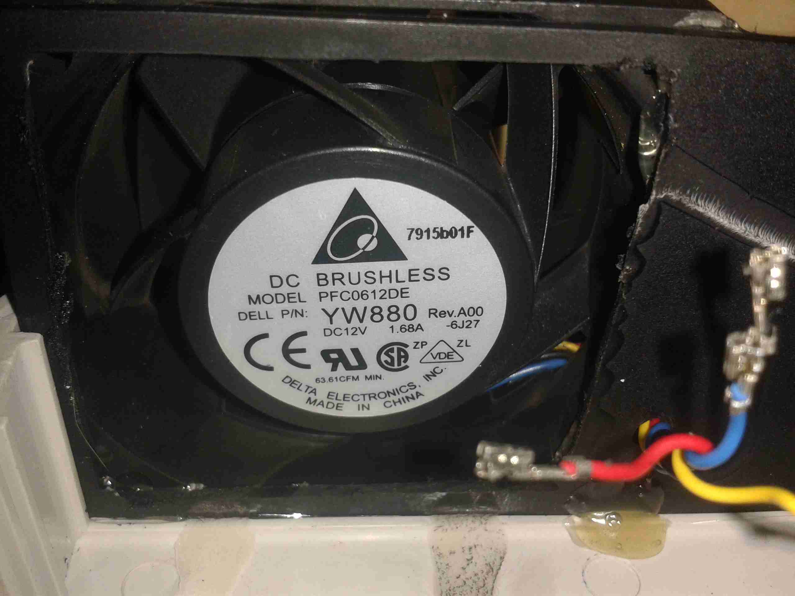
I’ve also upgraded on the fans again – these are PFC0612DE, with a higher airflow of ~70CFM at 12,000RPM.
To get the fans to run at minimum speed, the PWM control wire is connected directly to GND.
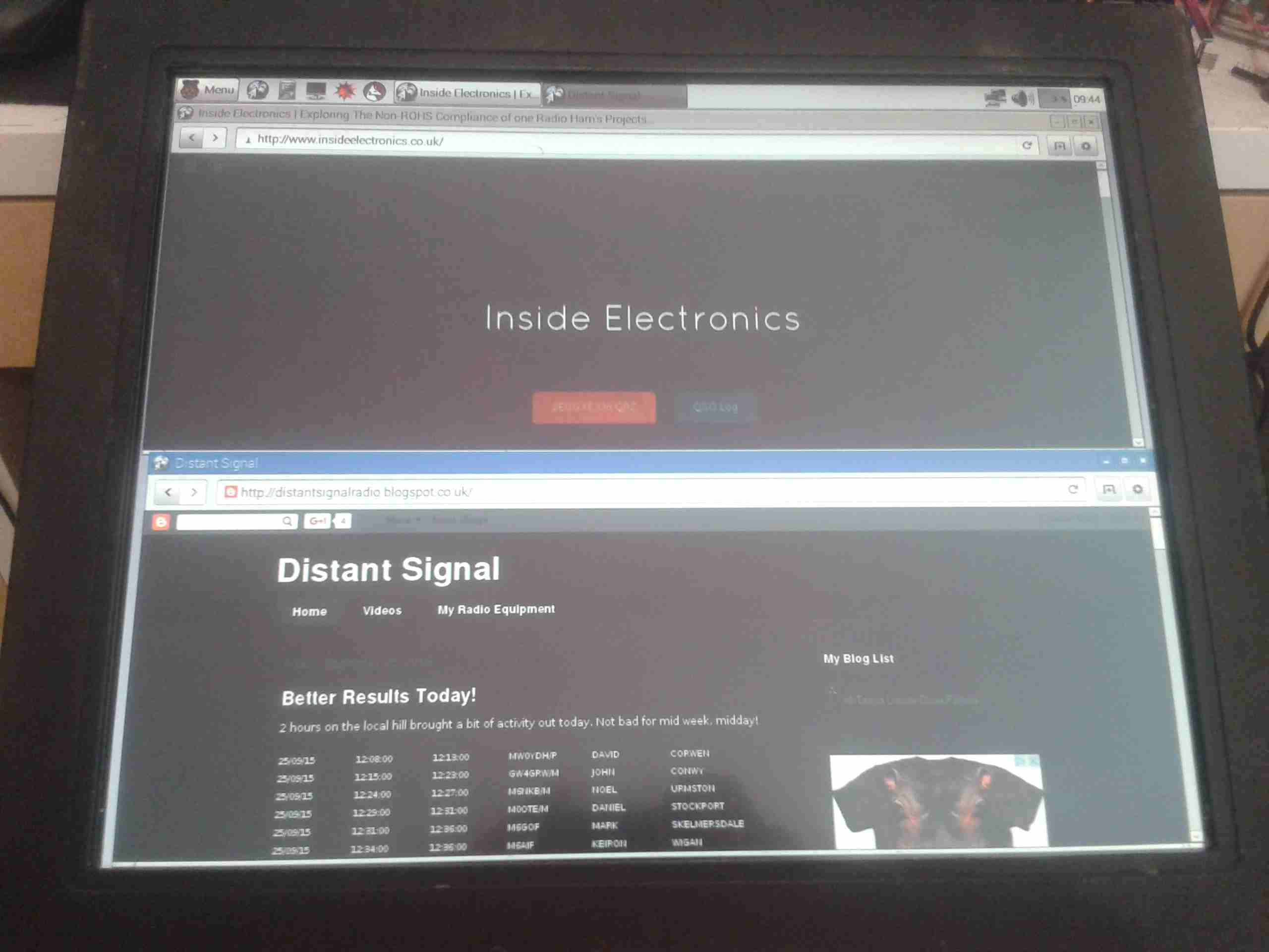
A while back I posted about a 3M Touch Systems industrial monitor that I’d been given. I had previously paired it with a Raspberry Pi Model B+, but for general desktop use it was just a little on the slow side.
Since the release of the Raspberry Pi 2, with it’s 4-core ARM Cortex CPU, things are much improved, so I figured I’d post an update with the latest on the system.
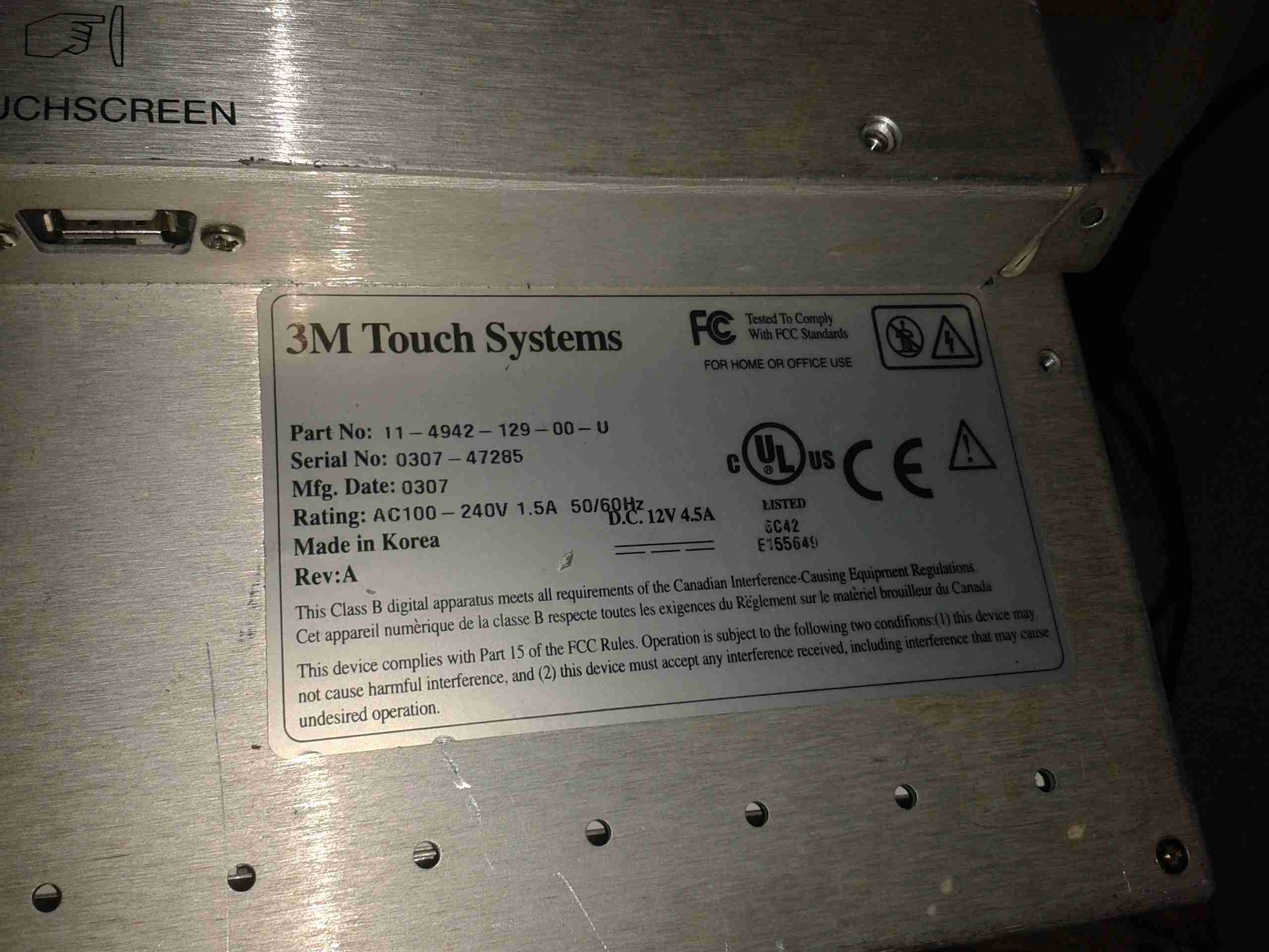
The monitor I’ve used is a commercial one, used in such things as POS terminals, service kiosks, etc. It’s a fairly old unit, but it’s built like a tank.
3M Panel
It’s built around a Samsung LTM170EI-A01 System-On-Panel, these are unusual in that all the control electronics & backlighting are built into the panel itself, instead of requiring an external converter board to take VGA to the required LVDS that LCD panels use for their interface.
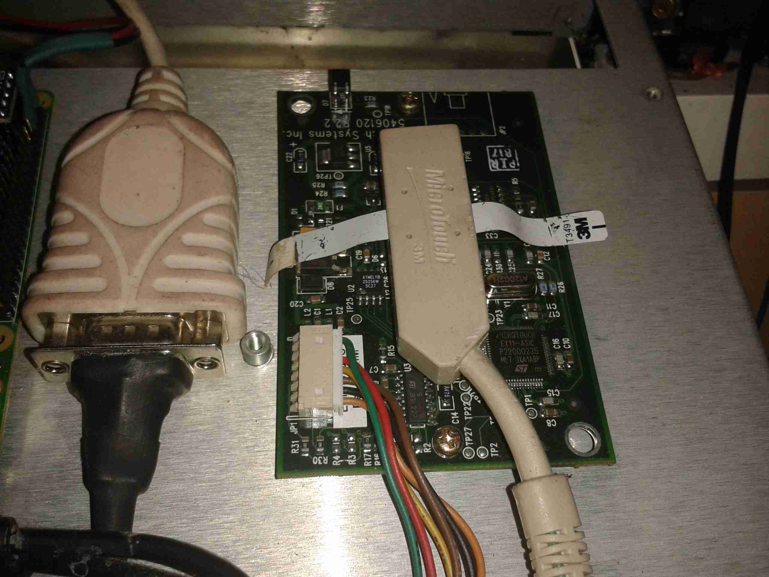
The touch section is a 3M Microtouch EXII series controller, with a surface capacitive touch overlay.
Touch Controller
Above is the touch controller PCB, with it’s USB-Serial converter to interface with the Pi.
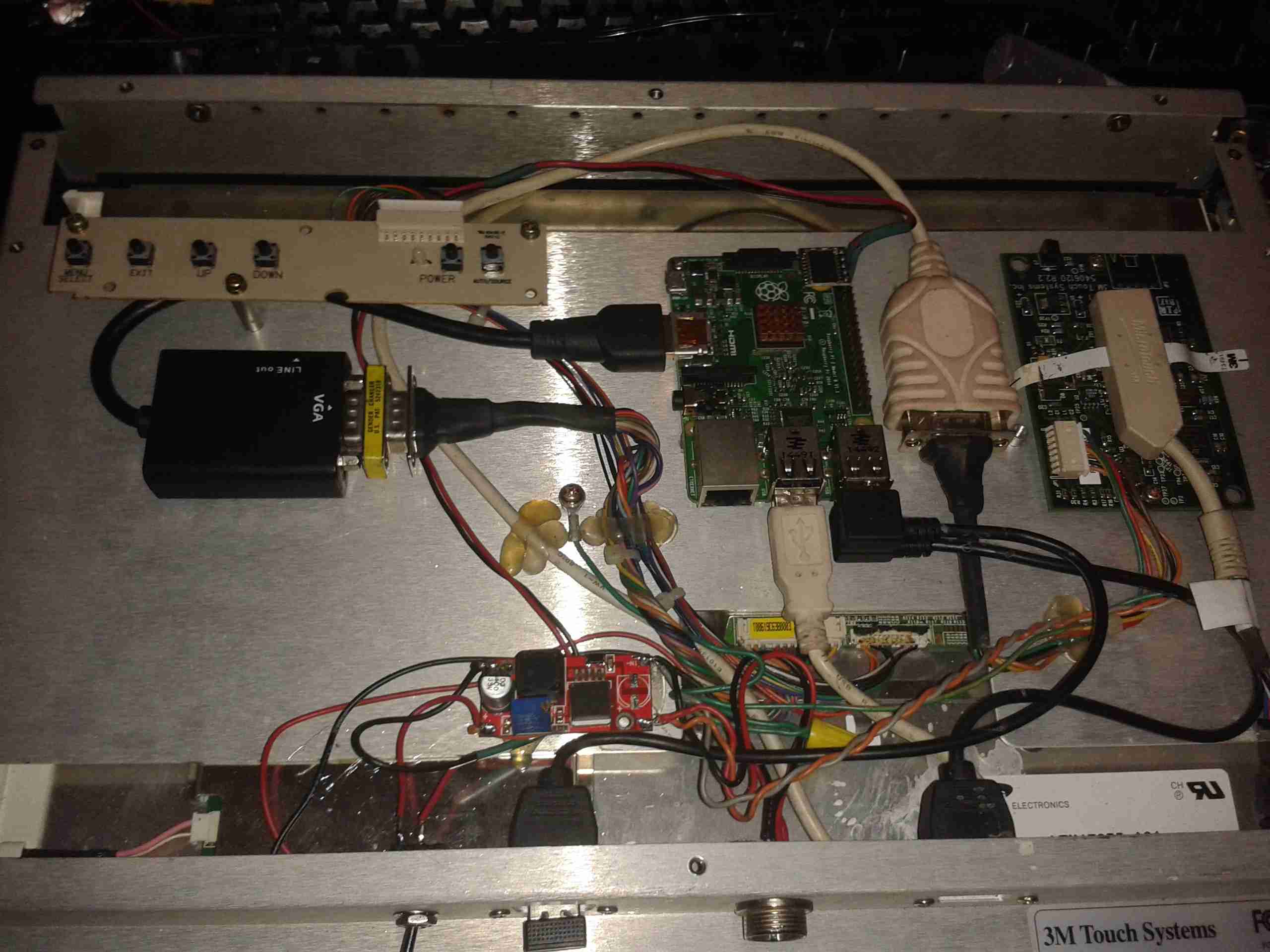
As there is much spare space inside the back of this monitor, I have mounted the Pi on a couple of spare screw posts, fitted USB ports where the original VGA & Serial connectors were in the casing, and added voltage regulation to provide the Pi with it’s required 5v.
Overview
Here’s the entire back of the panel, the Pi in the middle interfaces with a HDMI-VGA adaptor for the monitor, and the serial adaptor on the right for the touch. A small voltage regulator at the bottom of the unit is providing the 5v rail. There’s a switch at the bottom next to one of the USB ports to control power to the Pi itself. The panel won’t detect the resolution properly if they’re both powered on at the same time.
At 13.8v, the device pulls about 2A from the supply, which seems to be typical for a CCFL backlighted LCD.
Now the Raspberry Pi 2 has been released, it’s much more responsive for desktop applications, especially with a slight overclock.
Shameless Plug
A full disk image enabled for Desktop & 3M touch monitors is available below for others that have similar panels. This image only works for the Pi 2!
As I have posted about before, the main propulsion system onboard the boat is all hydraulic. To get the drive from the flywheel of the engine to the hydraulic pump stack, a custom drive plate was machined by Centa Transmissions over in Yorkshire, and a Centaflex A coupling was fitted to this.
Centaflex A Coupling
This coupling is a big rubber doughnut, bolted to a centre hub of steel. The steel hub is splined onto the input shaft of the hydraulic pump stack.
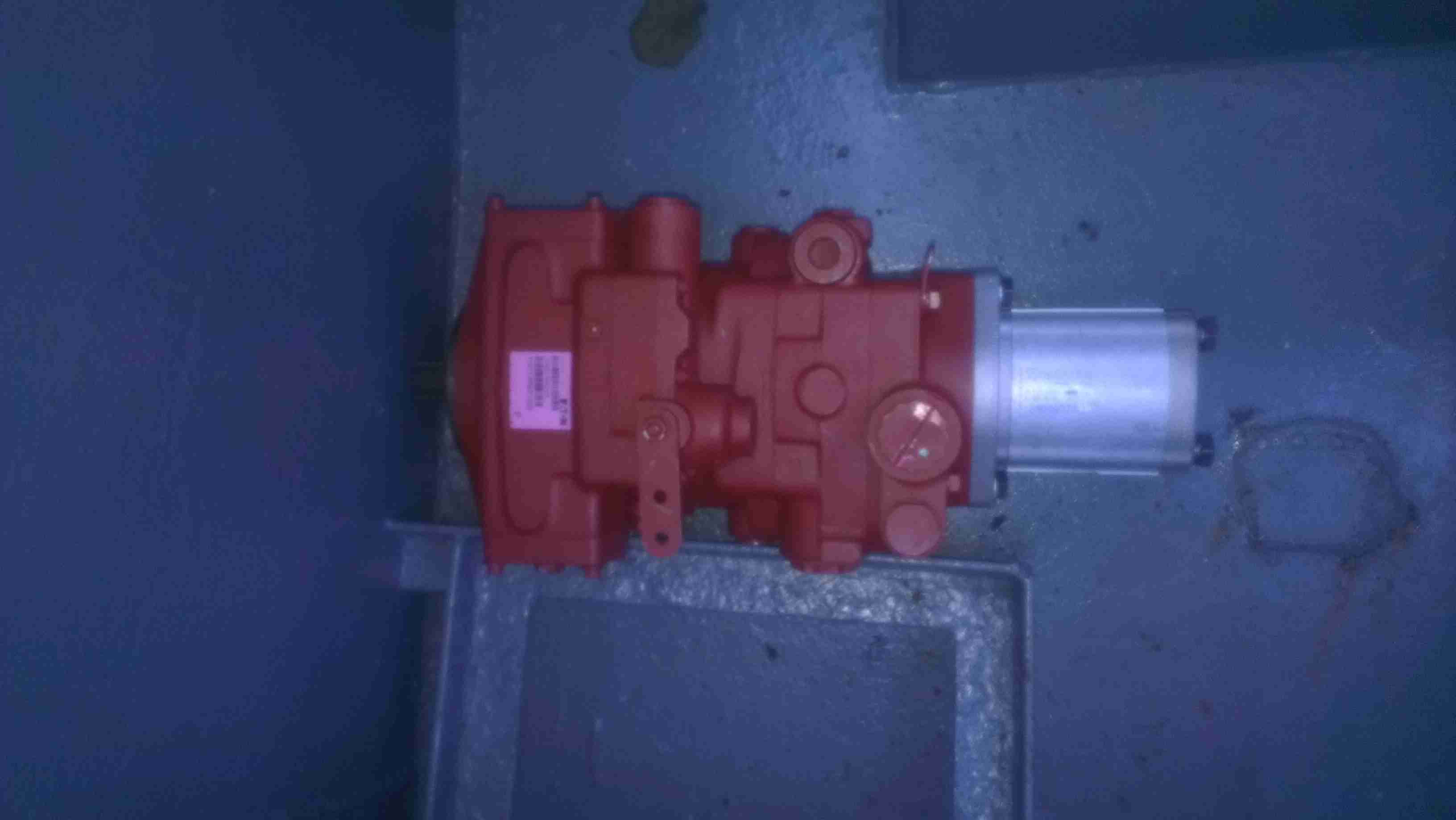
Pump Stack
The problem we’ve had is that to prevent the coupling from riding along the splines in operation, a pair of giant grub screws are provided in the side of the centre steel boss, that compress the splines to lock the device in place. These screws are a nightmare to get tightened down (the engineer from Centa who originally came to survey the system said we’d probably shear some tools off trying).
Because of this, the grub screws have loosened over the last 350-odd hours of running & this has had the effect of totally destroying the splines in the hub.
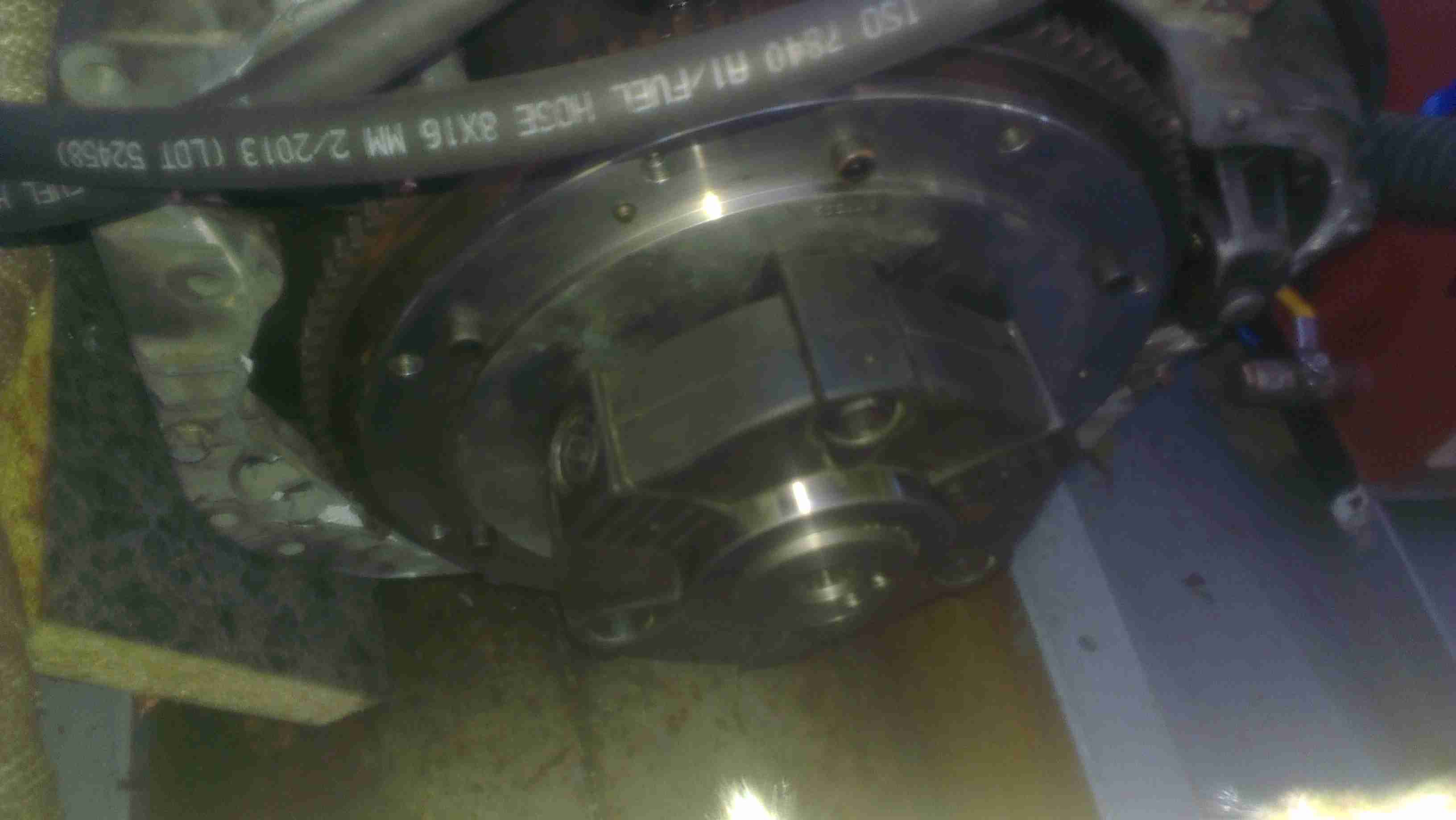
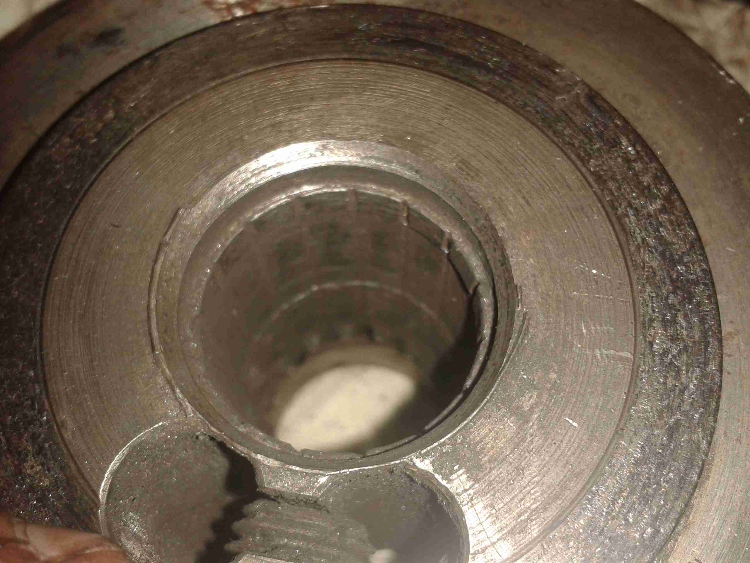
Spline Remains
Here’s the backside of the centre boss, with what remains of the splines, the figure-8 shaped gap on the right is where the securing grub screws deform the steel to lock the coupling into place.
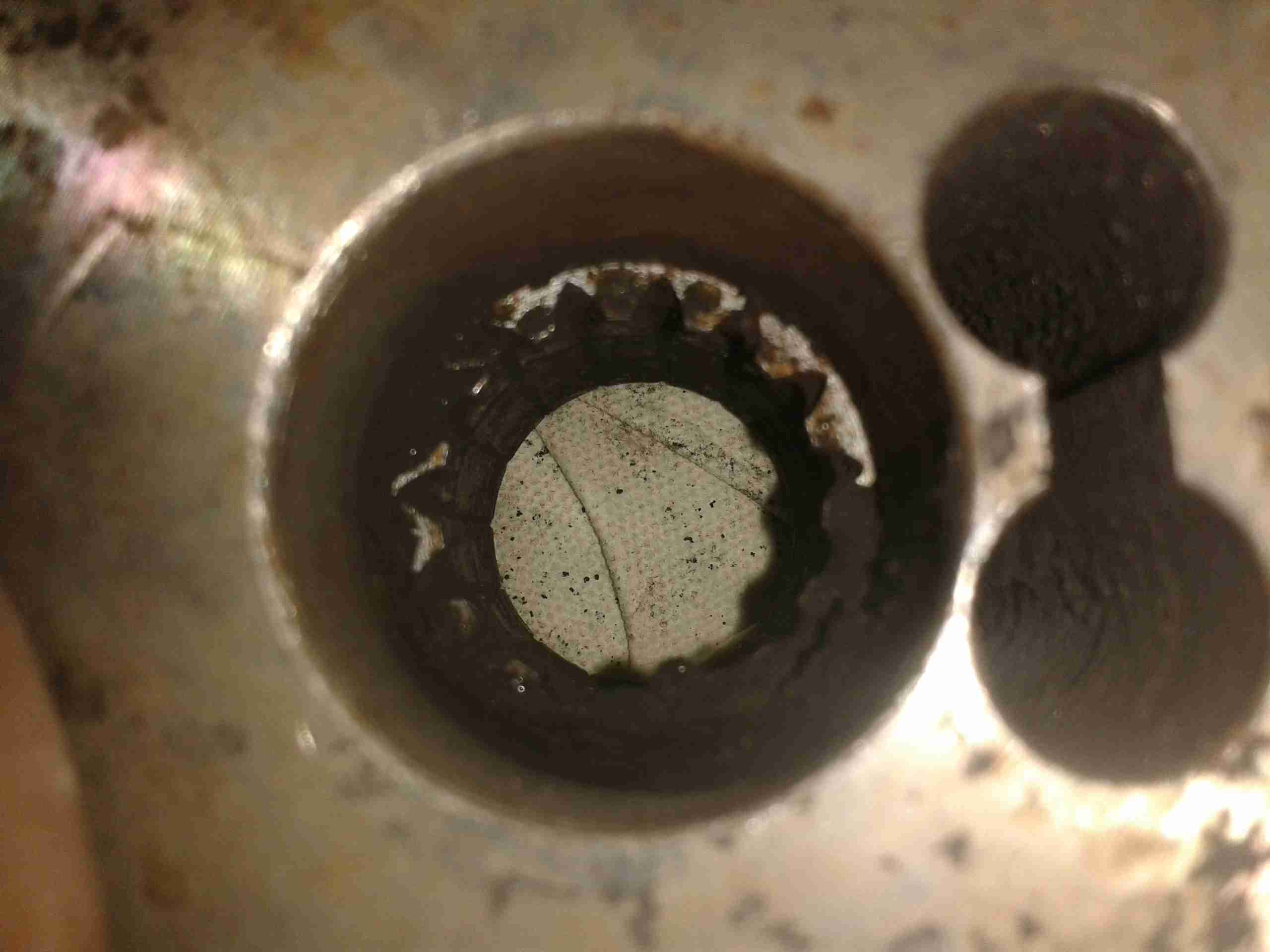
No More Splines
Here’s the other side of the coupling, showing the damage. The splines have effectively been totally removed, as if I’d gone in there with a boring bar on the lathe. Luckily this part isn’t too expensive to replace, and no damage was done to the input shaft of the hydraulic pump stack (Mega ££££). Quite luckily, this damage got to the point of failure while running the engine on the mooring, so it didn’t leave us stranded somewhere without motive power.
The power supplies I have recently built from surplus Cisco switch boards have started displaying a rather irritating problem – continual load of over 9A causes the supplies to shut down on overheat.
This was partially expected, as the original switches that these supplies came from are cooled by a monster of a centrifugal blower that could give a Dyson a run for it’s money. The problem with these fans is that they’re very loud, draw a lot of power (3-4A) and aren’t small enough to fit into the case I’ve used for the project.
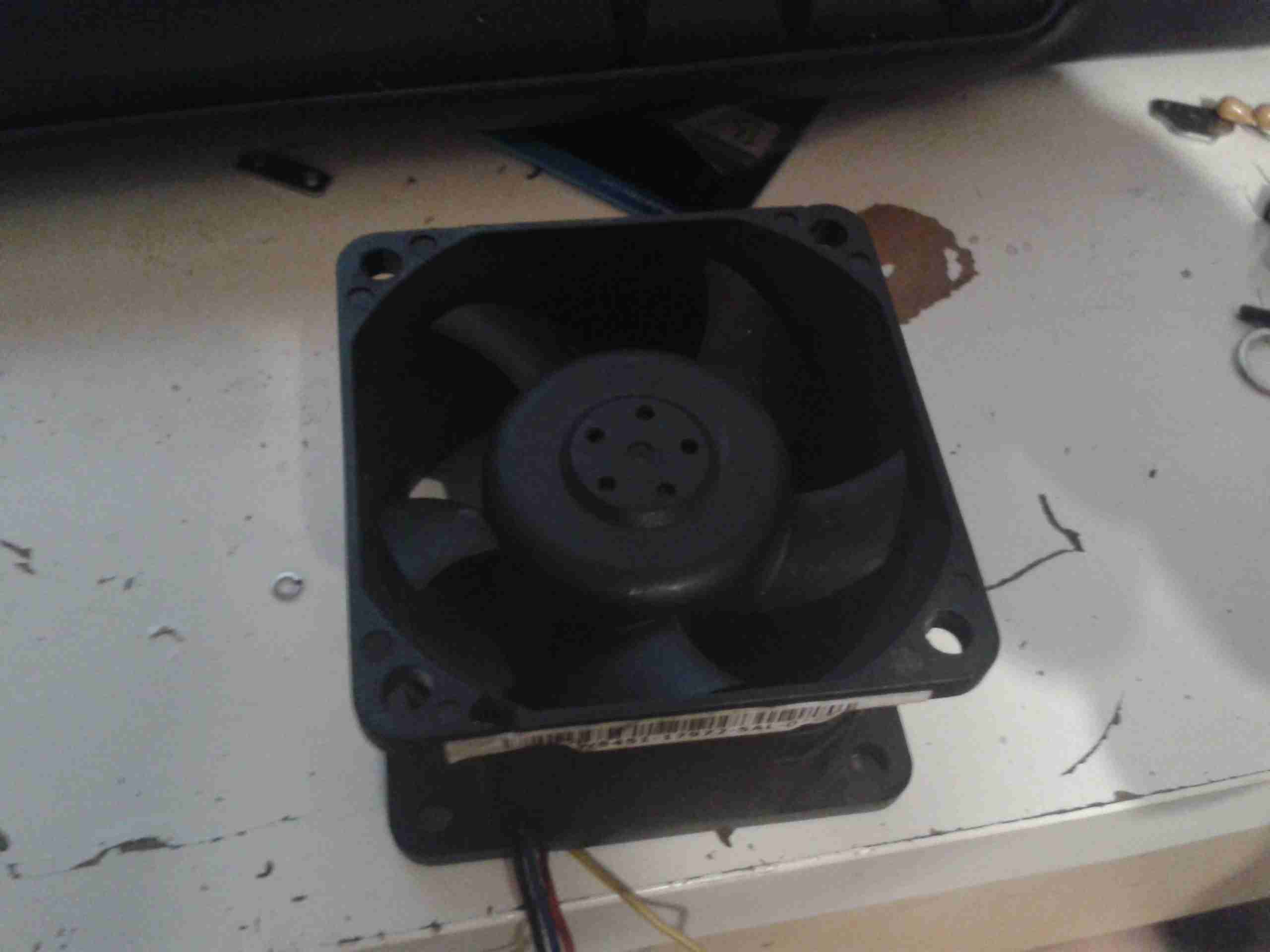
The solution of course, is a bigger fan – I’ve got some Delta AFB0612EHE server fans, these are very powerful axial units, shifting 60CFM at 11,000RPM, with a power draw of 1.12A.
They’re 60mm diameter, so only just fit into the back of the case – although they stick out of the back by 40mm.
Monster Fan
Here’s the fan, not the beefiest I have, but the beefiest that will fit into the available space.
These will easily take fingers off if they get too close at full speed, so guards will definitely be required.
To reduce the noise (they sound like jet engines at full pelt), I have ordered some PWM controllers that have a temperature sensor onboard, so I can have the fan run at a speed proportional to the PSU temperature. I will probably attach the sensor to the output rectifier heatsink, since that’s got the highest thermal load for it’s size.
My other monitors are a different model, and have a slightly different main PCB inside, but the process is mostly the same for converting these to 12v supply.
Main PCB
In this monitor type, there is only a single board, with all the PSU & logic, instead of separate boards for each function.
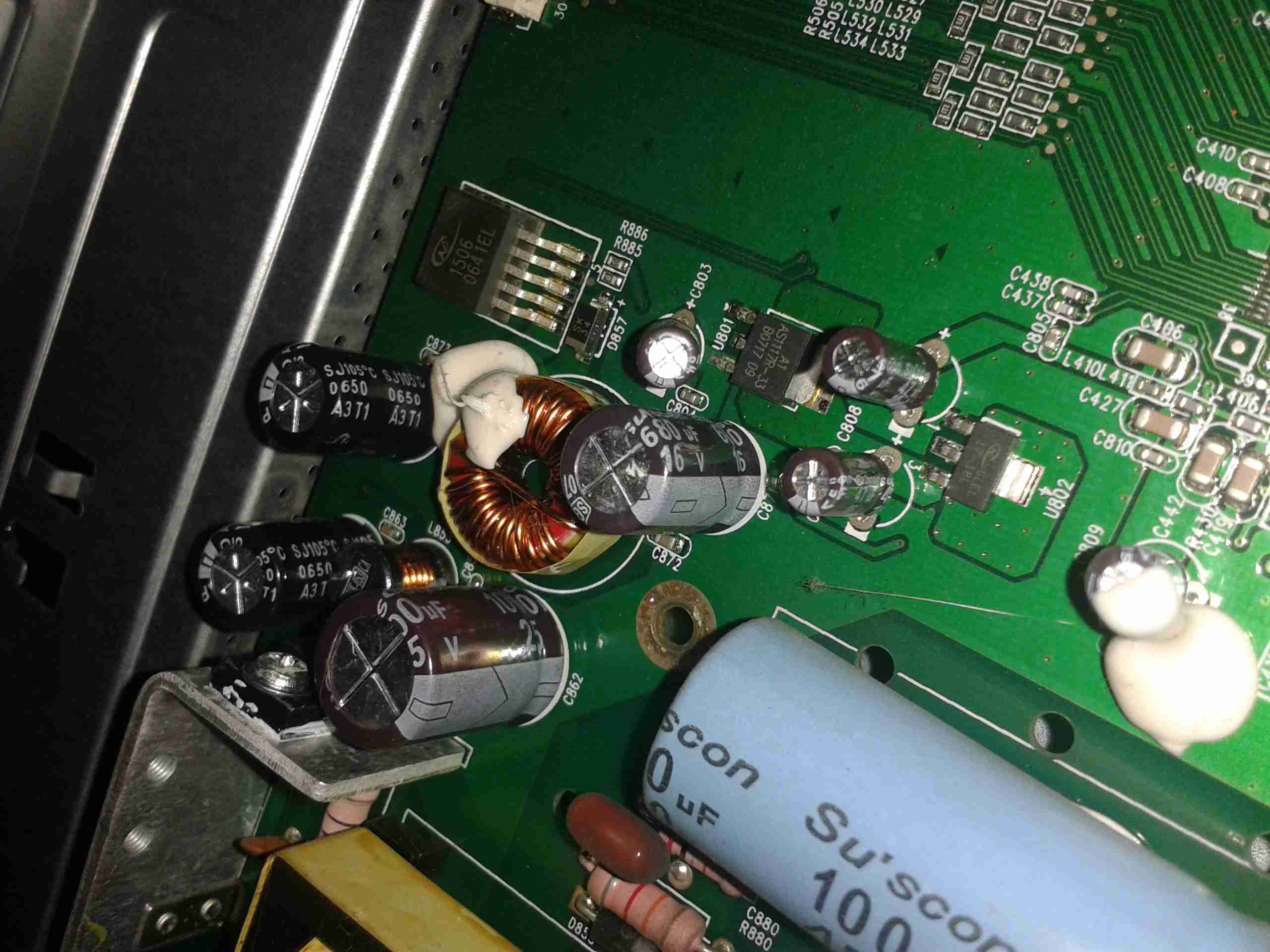
PSU Closeup
This monitor is slightly different in it’s power supply layout. The mains supply provides only a single 12v rail, which is then stepped down by a switching converter to 5v, then by smaller linear regulators to 3.3v & 1.8v for the logic. This makes my life easier since I don’t have to worry about any power conversion at all.
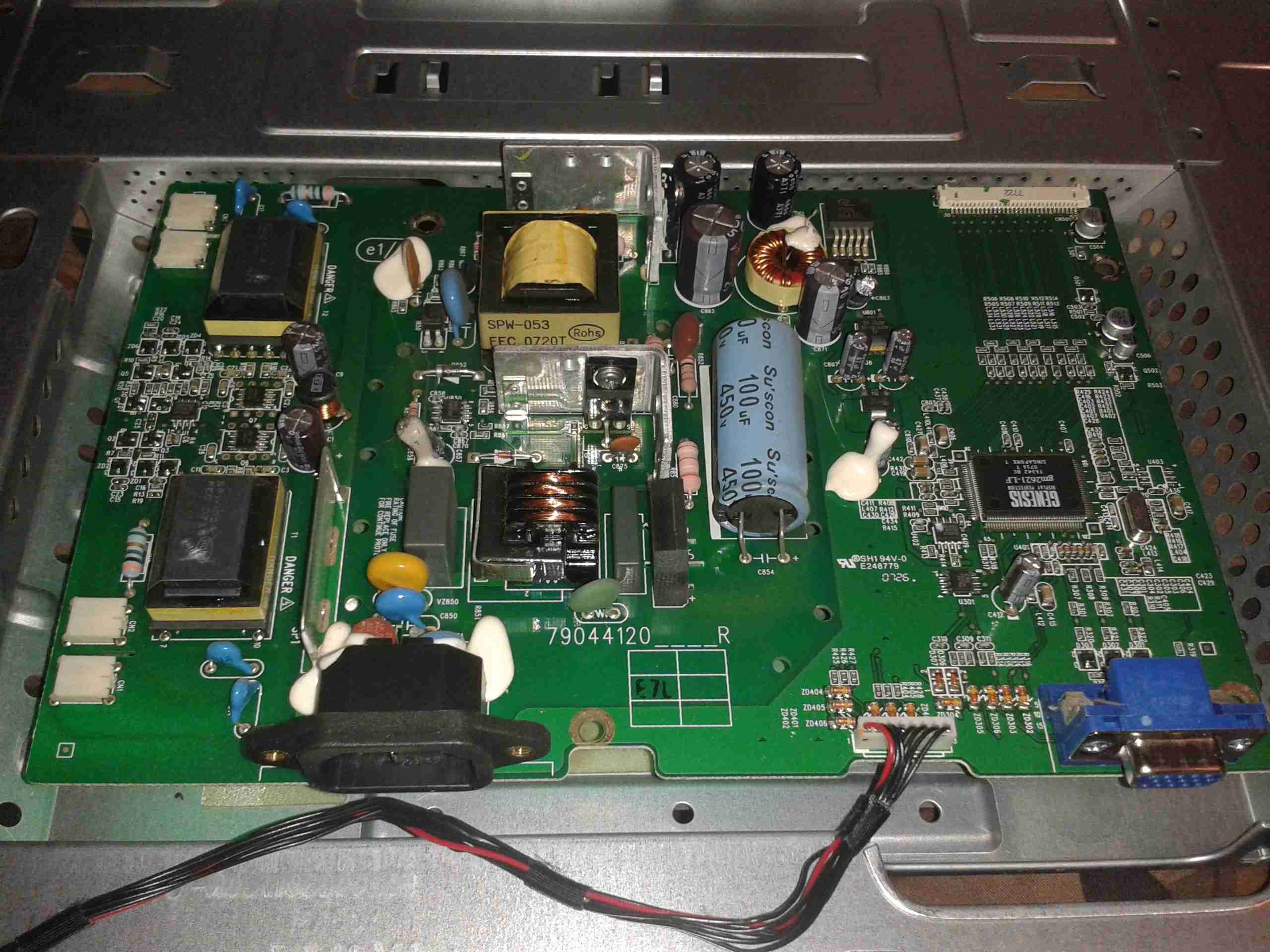
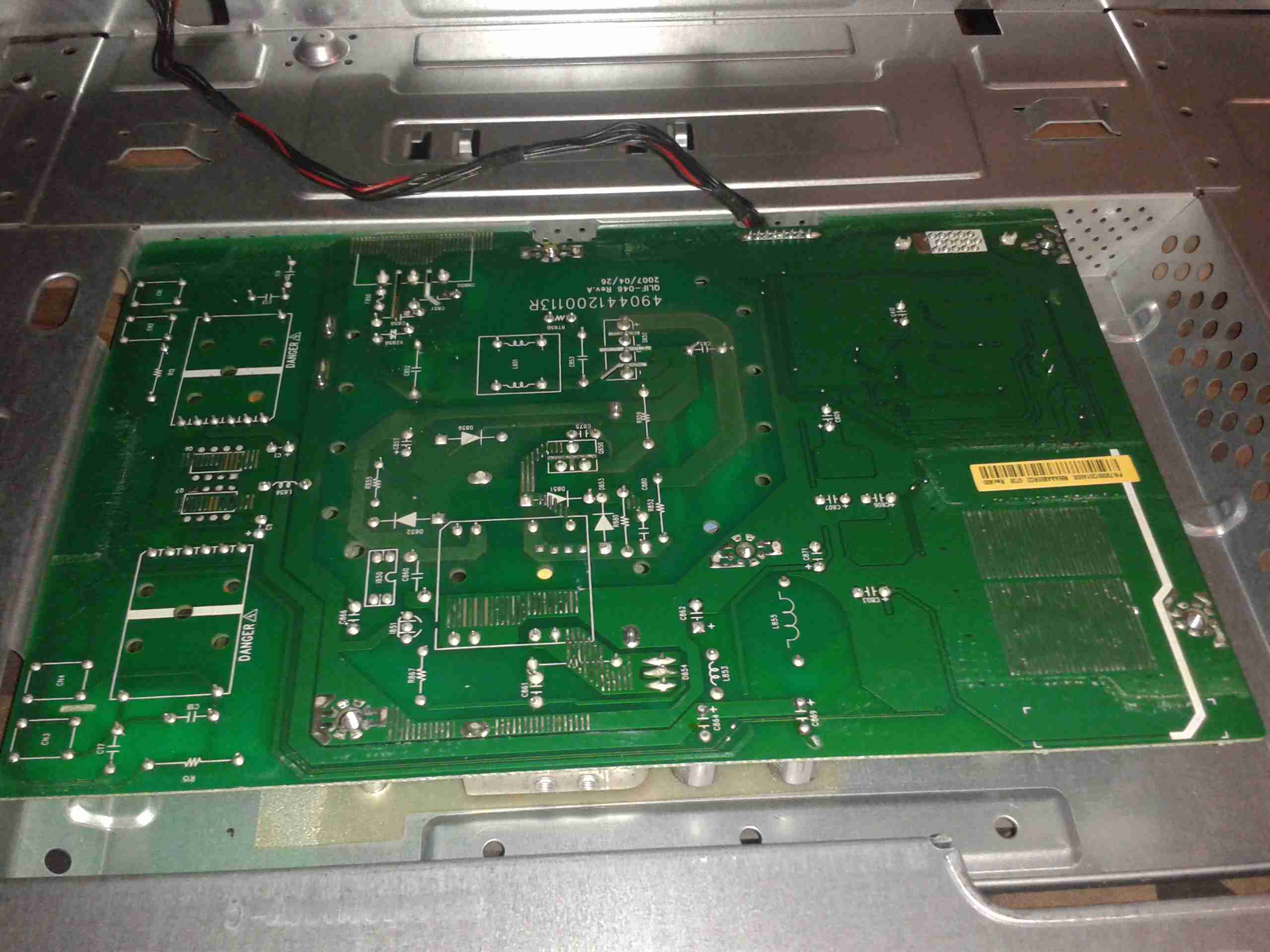
PCB Reverse
Here’s the backside of the PCB, the mains PSU section is in the centre.
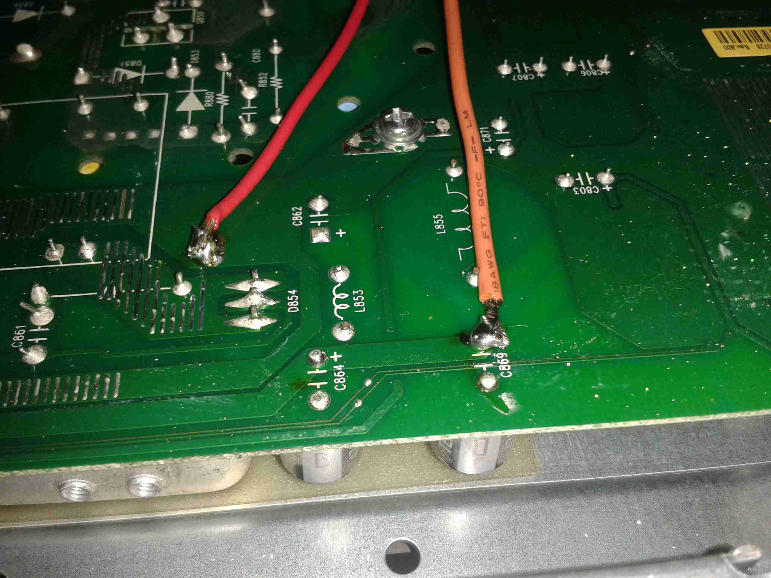
Attachment Points
Here’s the pair of 12v supply wires soldered onto the main board, onto the common GND connection on the left, and the main +12v rail on the right. I’ve not bothered with colour coding the wiring here, just used whatever I had to hand that was heavy enough to cope with a couple amps.
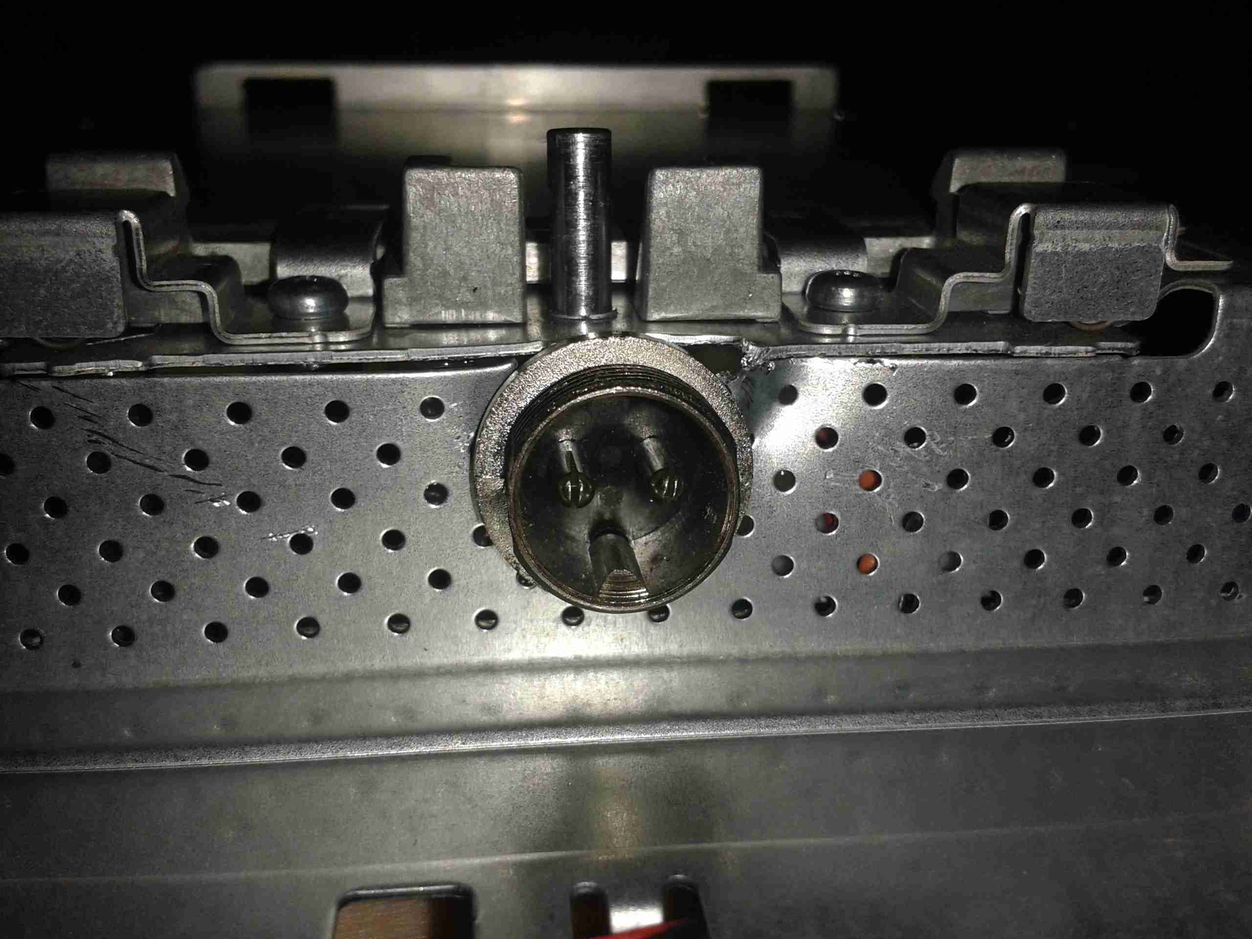
12v Socket
A small mod later with a cone drill & the 12v input socket is mounted in the LCD frame.
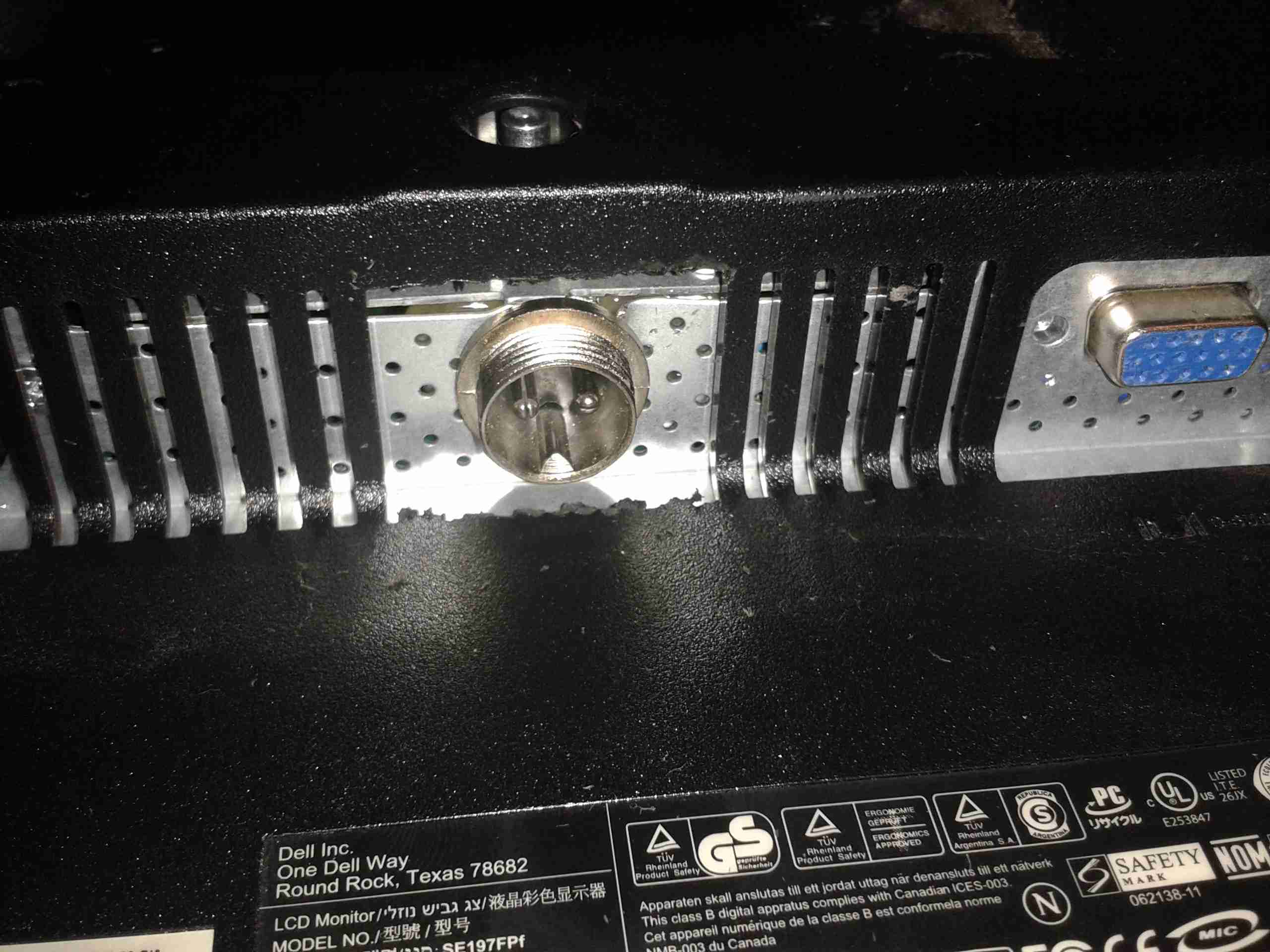
Casing Mod
Some light removal of plastic & the back cover fits back on. Current draw at 13.8v is ~2A.
I’m still on my crusade of removing every trace of 240v mains power from my shack, so next up are my computer monitors.
I have 4 Dell monitors, of various models, hooked up to my main PC.
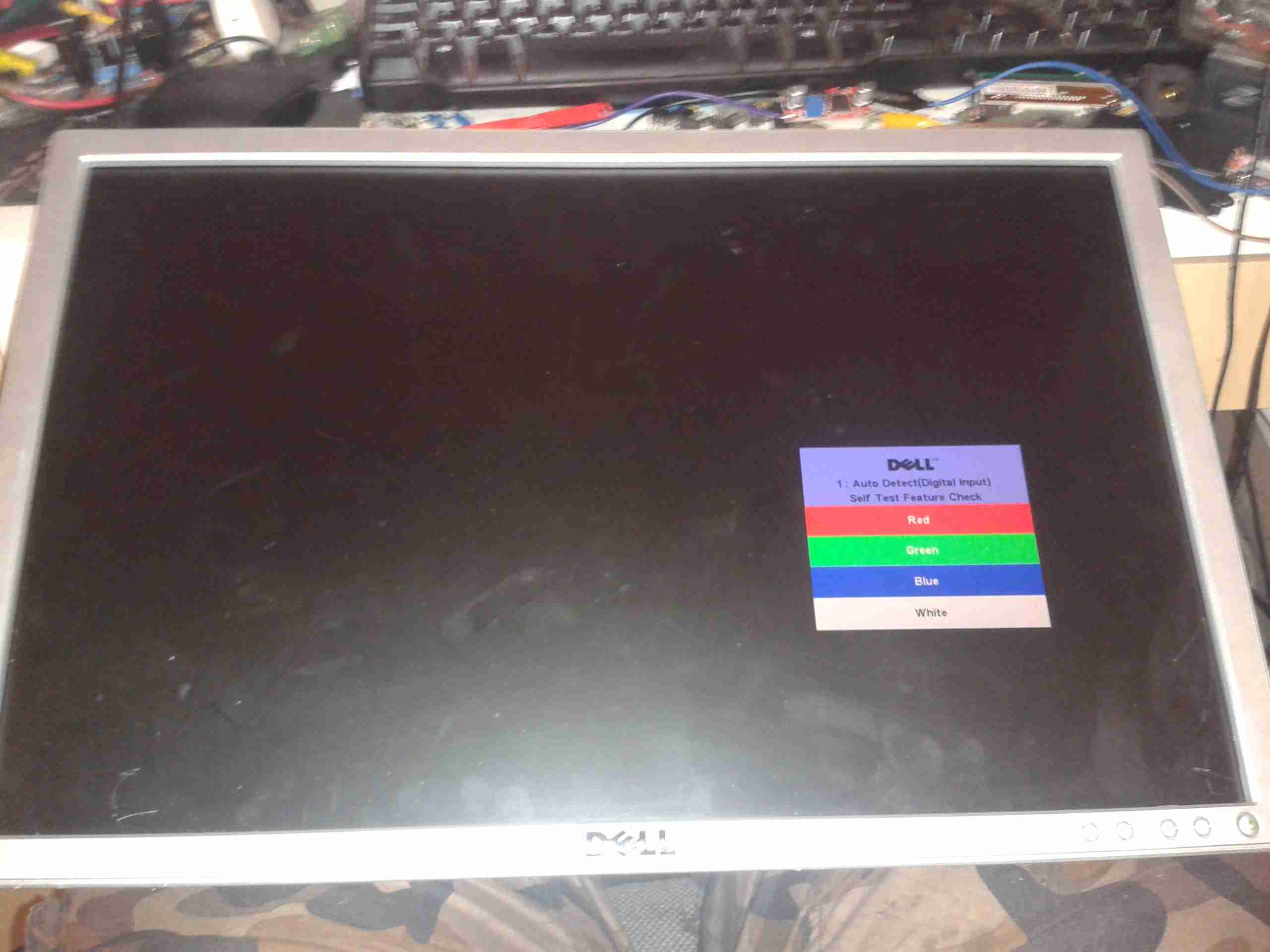
The monitor here is a Dell E207WFPc 20″ widescreen model. There will be more when I manage to get the others apart to do the conversion. However I’m hoping that the PSU boards are mostly the same.
Panel Removed
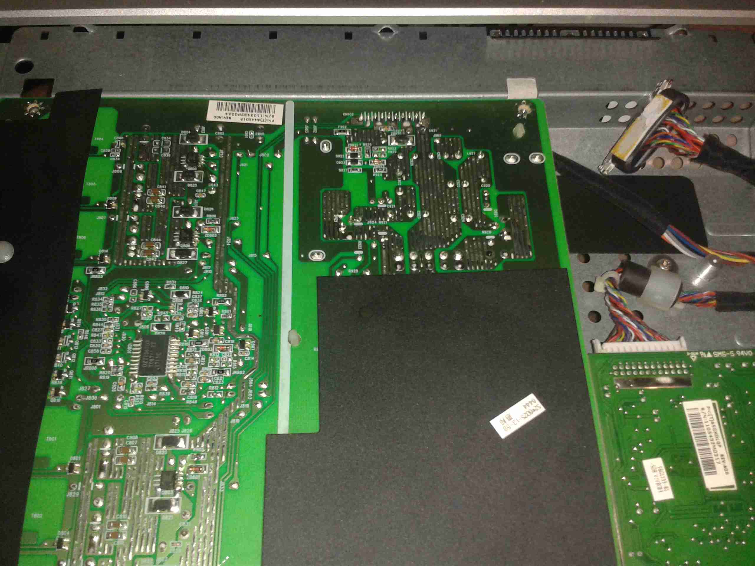
There are no screws holding these monitors together, the front bezel is simply clicked into place in the back casing, these clips are the only thing that holds the relatively heavy glass LCD panel & it’s supporting frame! The image above shows the panel removed. The large board on the left is the power supply & backlight inverter, the smaller one on the right is the interface board to convert the DVI or VGA to LVDS for the LCD panel itself.
PSU Board
Here’s a closeup of the PSU board, the connector at centre right at the top of the PCB is the main power output, and also has a couple of signals to control the backlight inverter section of the PSU, on the left side. The PSU requirements for this monitor are relatively simple, at 14.5v for the backlight & 5v for the logic board.
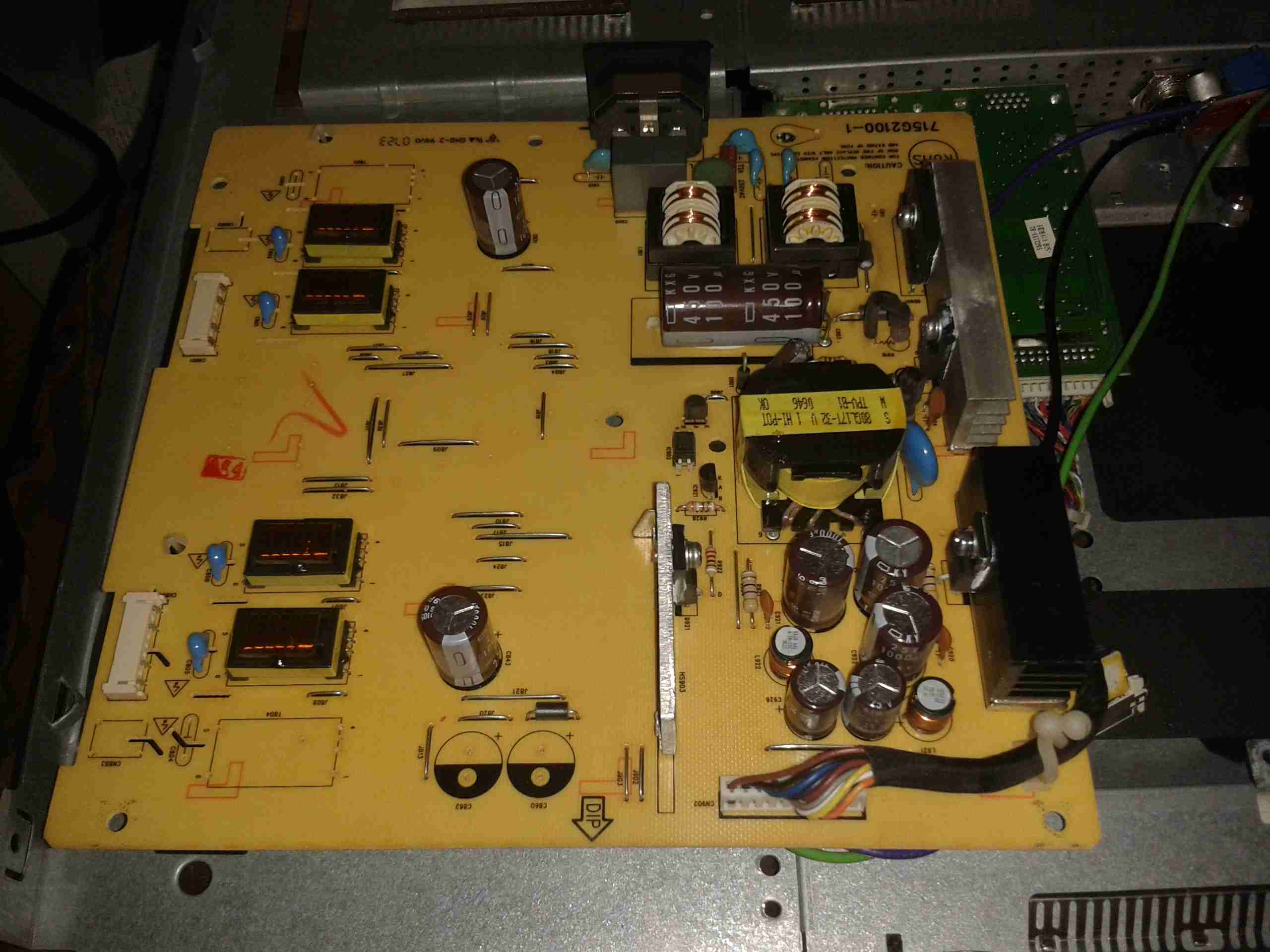
PSU
Here’s the top of the PSU board, very simple with the mains supply on the right side, and the backlight inverter transformers on the left.
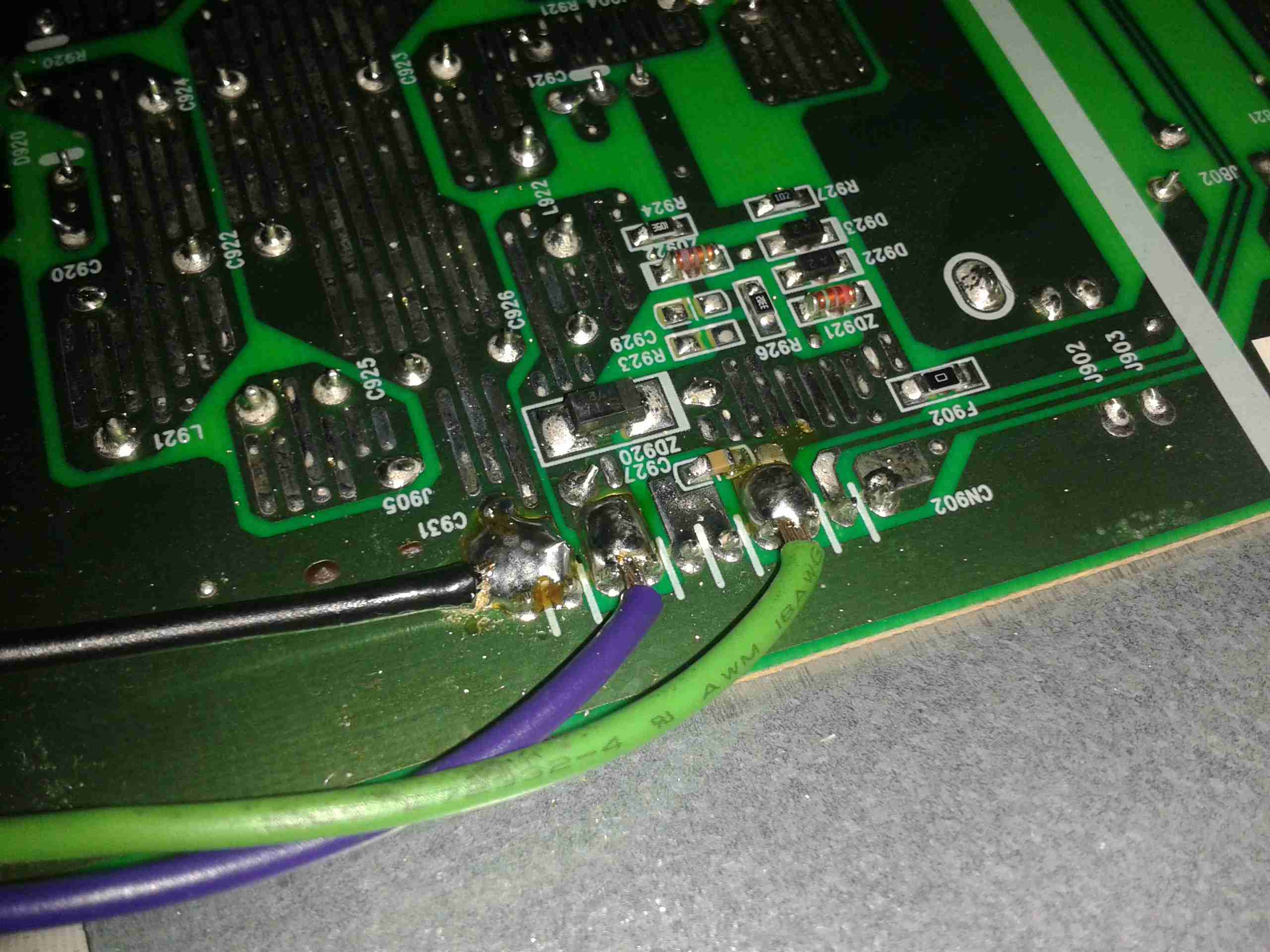
Hooked In
Here I’ve hooked into the power rails on the supply, to attach my own 12v regulators. The green wire is +14.5v, and the purple is +5v. Black is common ground.
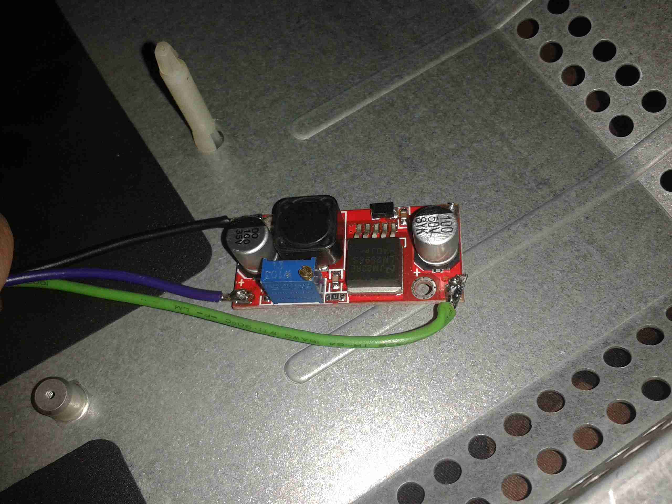
5v Regulator
On doing some testing, the backlight inverter section doesn’t seem to mind voltages between 11.5-14.5v, so a separate regulator isn’t required there. Even running off batteries that’s within the range of both charging & discharging. The only regulator required is a 5v one to reduce the input voltage for the logic PCB.
First Test
On applying some 12v power to the regulator input, we have light! Current draw at 12.5v is 2.65A for a power consumption of 33W.
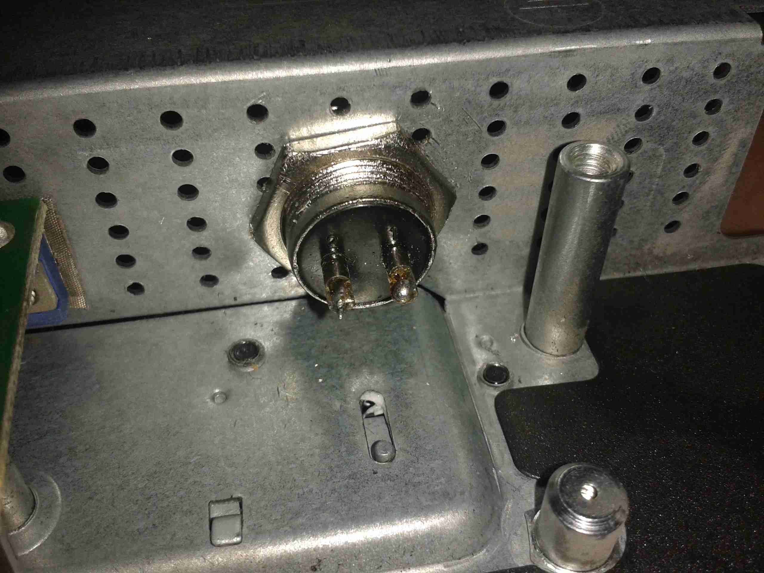
12v Input
There’s plenty of room in the back casing to mount a 12v input socket, I have left the mains supply intact so it can be used on dual supply.
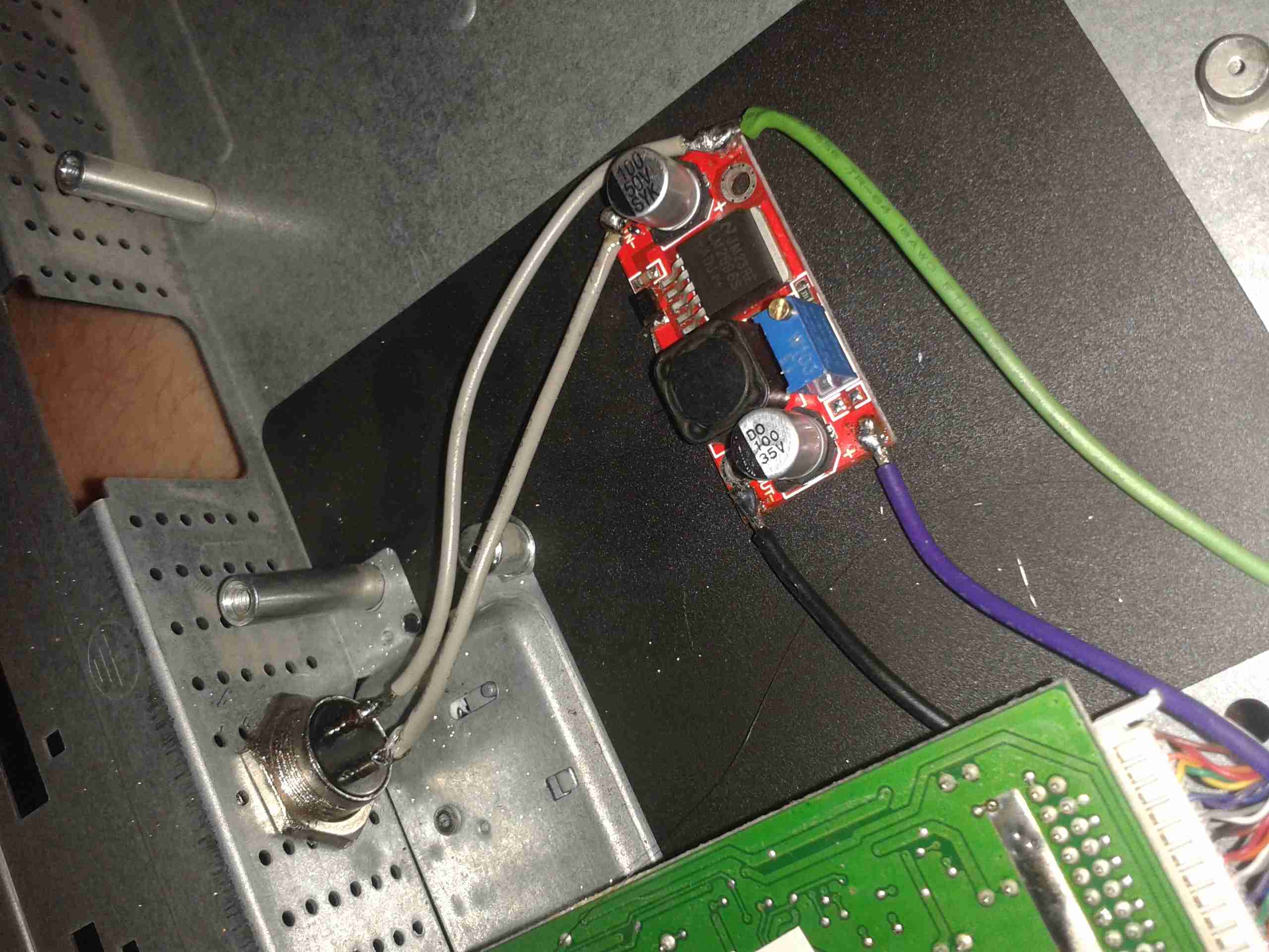
Final Wiring
Here’s the 5v regulator mounted on the back of the casing, all wired up & ready to go.
I’ve had a couple of viewfinder CRT modules for a while, & haven’t done much with them, so I decided to make a very small B&W monitor.
CRT
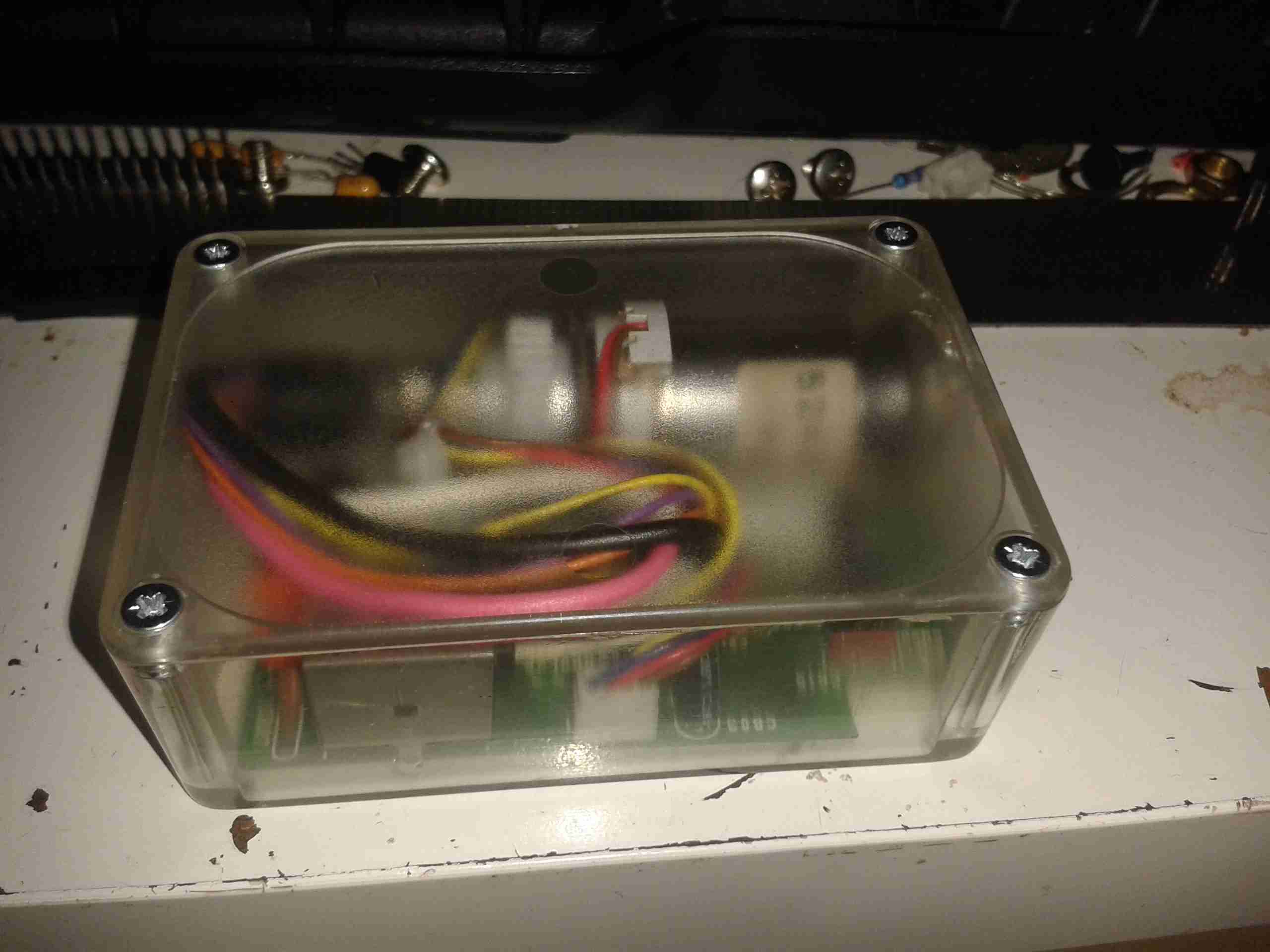
I ordered a small transparent ABS box when I made a large order with Farnell, that turned out to be just about the perfect size for the project! The CRT & PCB barely fit into the space. The face of the CRT itself is about 17mm across.
Module Installed
Here’s the main PCB & tube fully installed into the case. Barely enough room for a regulator left over!
Power is provided by a simple LM7809 IC to take a standard 12v input.
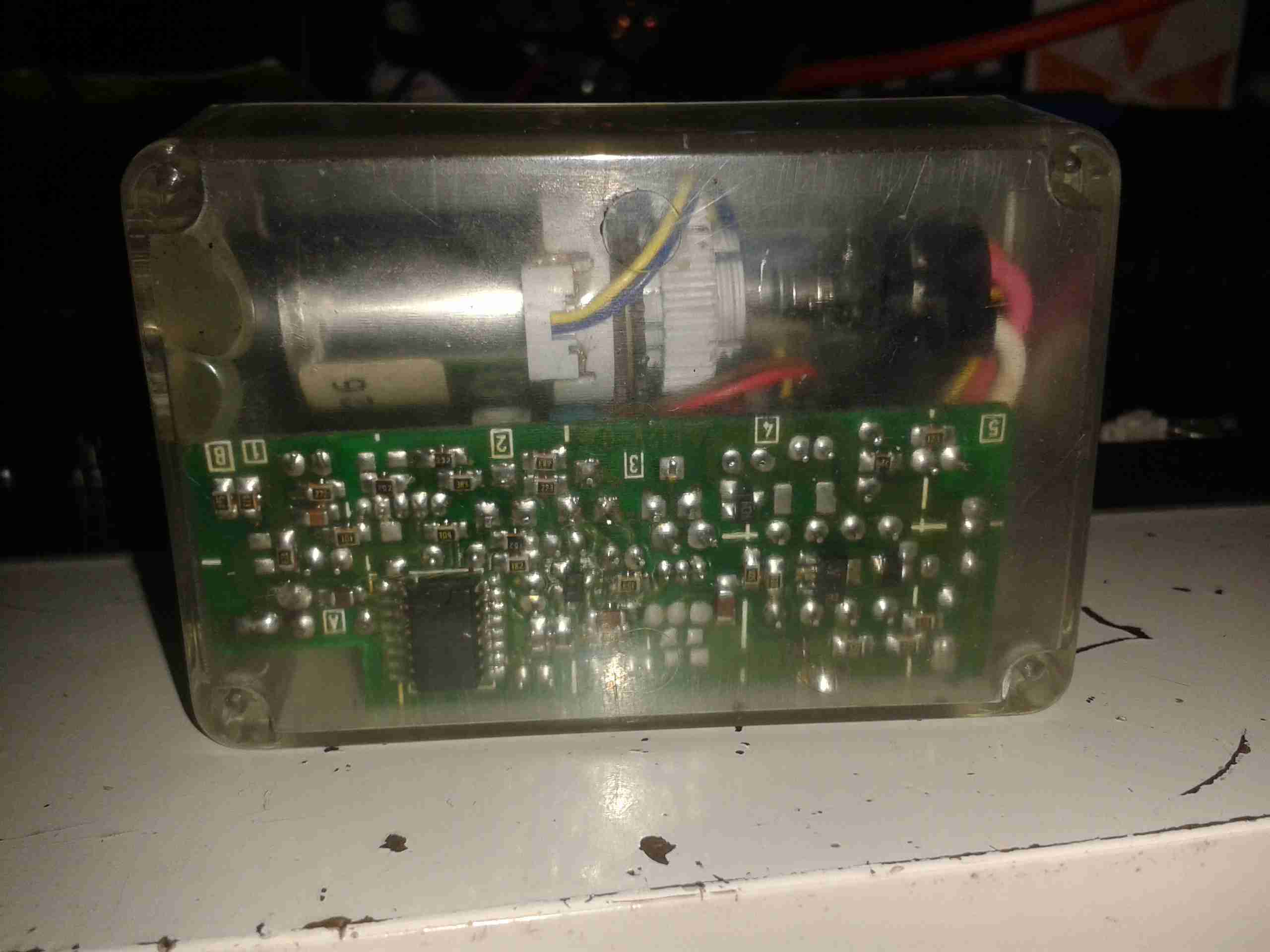
Module Rear
Rear of the case, showing the fit of the control board.
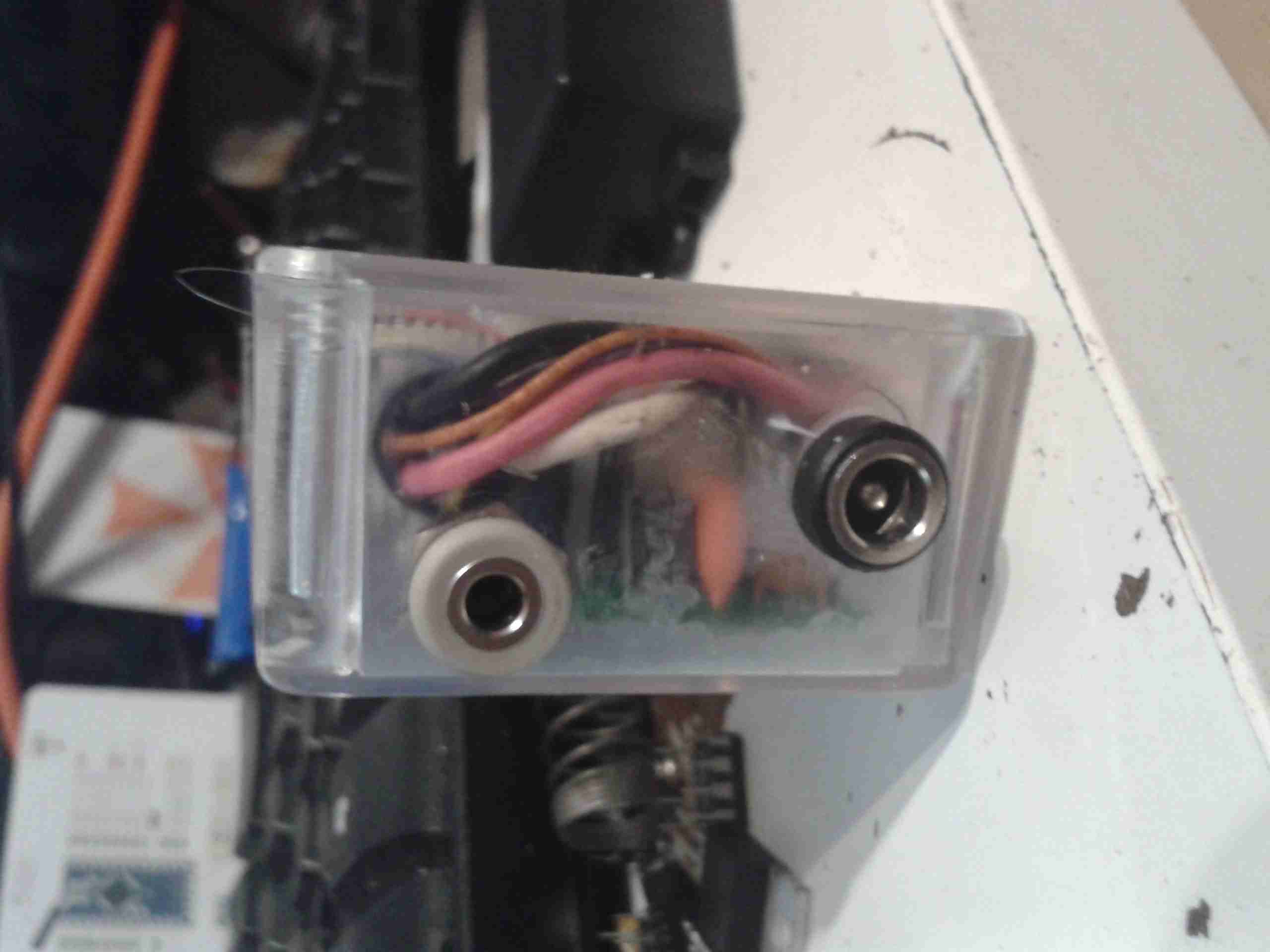
Connections
Here’s the back of the monitor, with the DC input jack & a 3.5mm 4-pole jack for audio & video. This allows simple connection to many devices, including the one I’ll use the most – the Raspberry Pi.
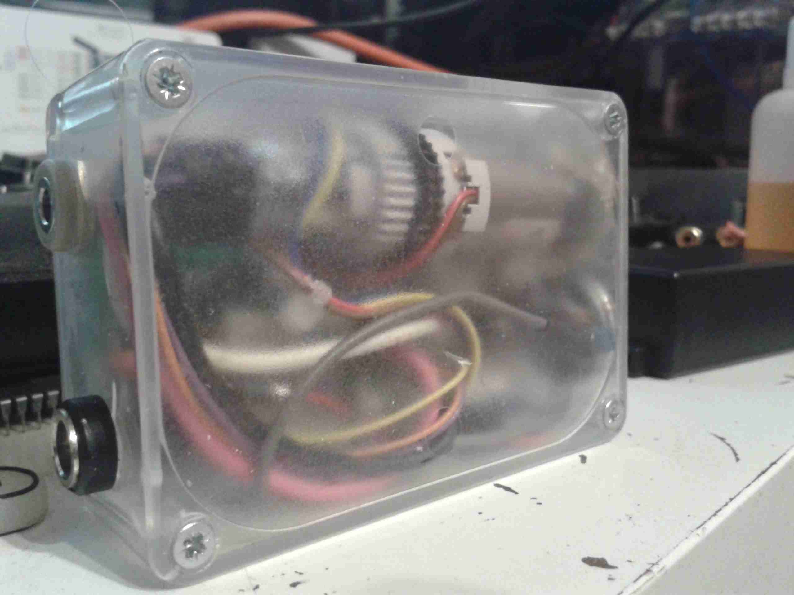
Completed
Completed monitor. Audio is handled by a very small 20mm speaker, currently mounted just below the CRT face.
Current draw from a 13.8v supply is 117mA.
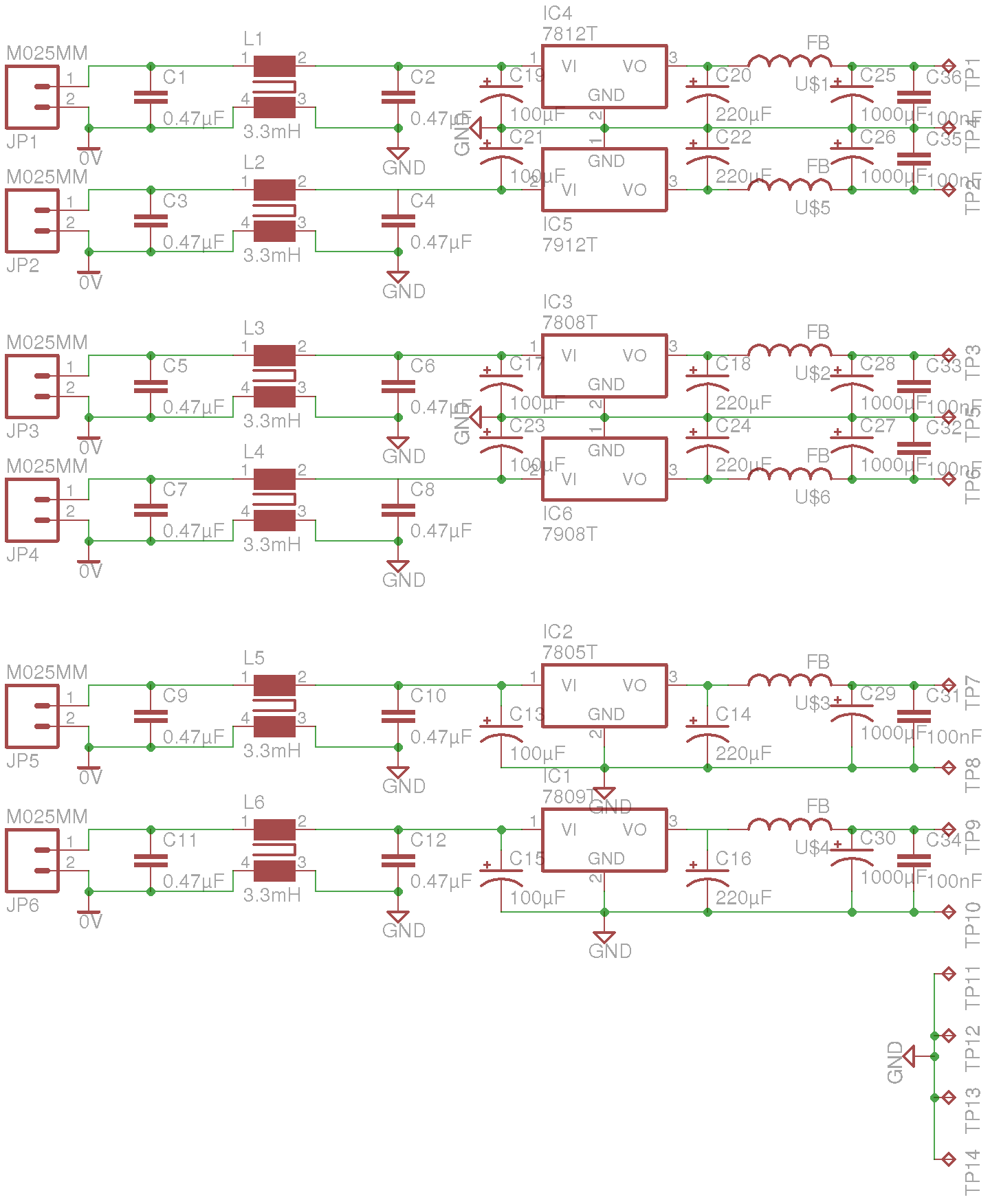
Finally, here’s the last part of the Rigol 12v DC Power Supply project, the linear post regulation section to remove some of the ripple.
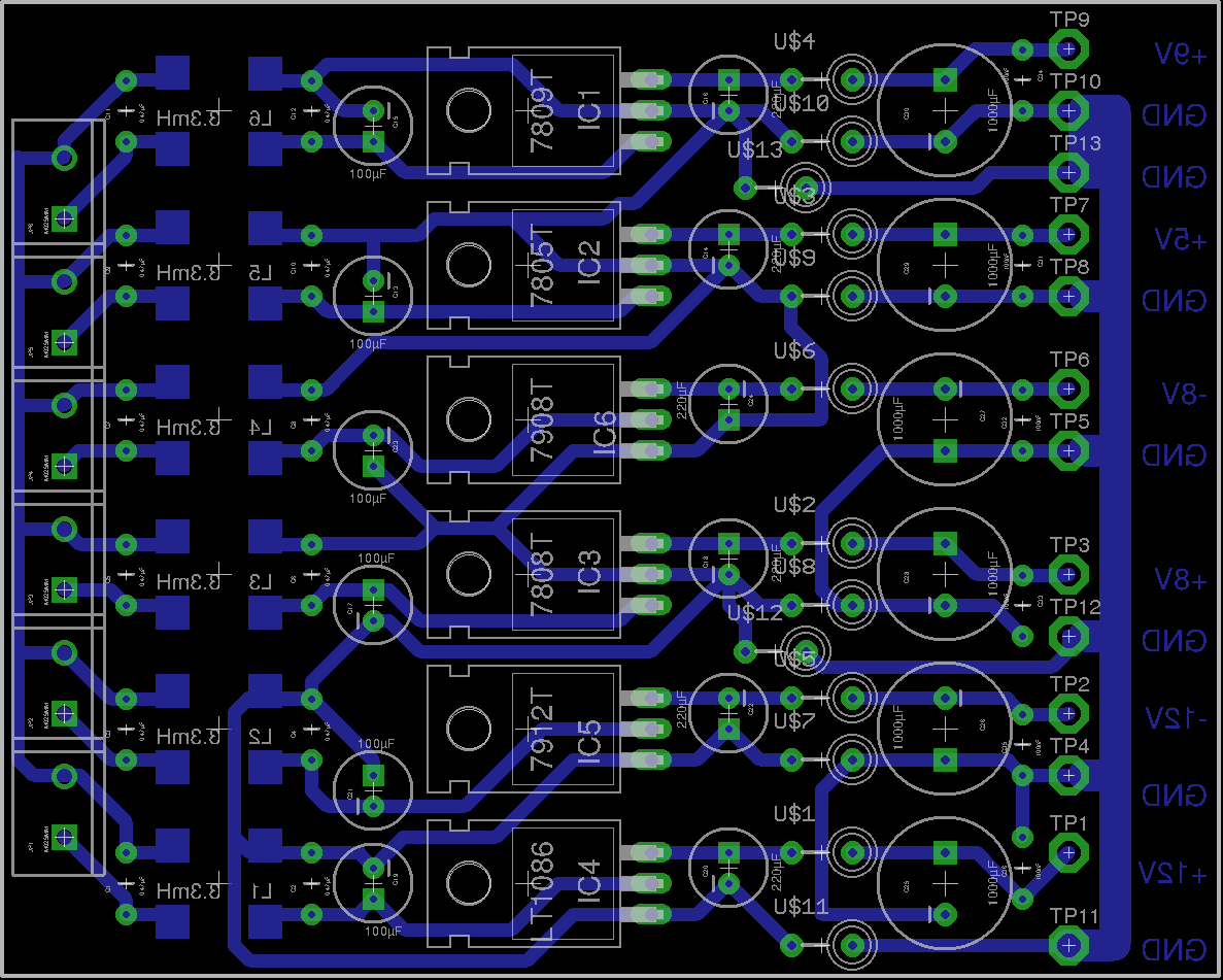
I have made a couple of layout adjustments since the last post about this part of the project – a little more filtering on the DC outputs. As usual the Eagle project files are at the bottom of the post for those who might find them useful.
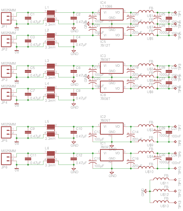
Updated PCBUpdated Schematic
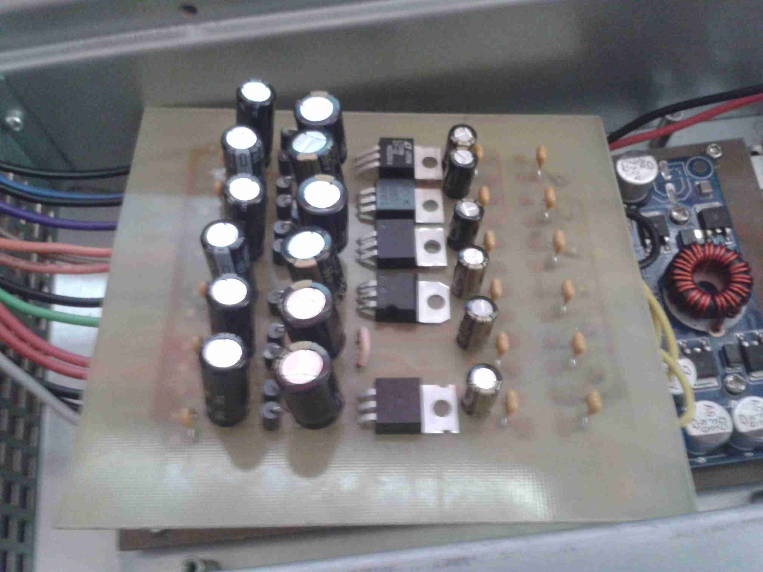
Completed PCB
Here’s the completed PCB, partially installed in the back of the scope. The missing regulator is the 5v one, since I already have a source of clean 5v from my original attempt at the supply, it’s not a problem not using a linear after the switcher. The filtering is the same on all channels, input from the switchers is on the right, outputs to the scope on the left.
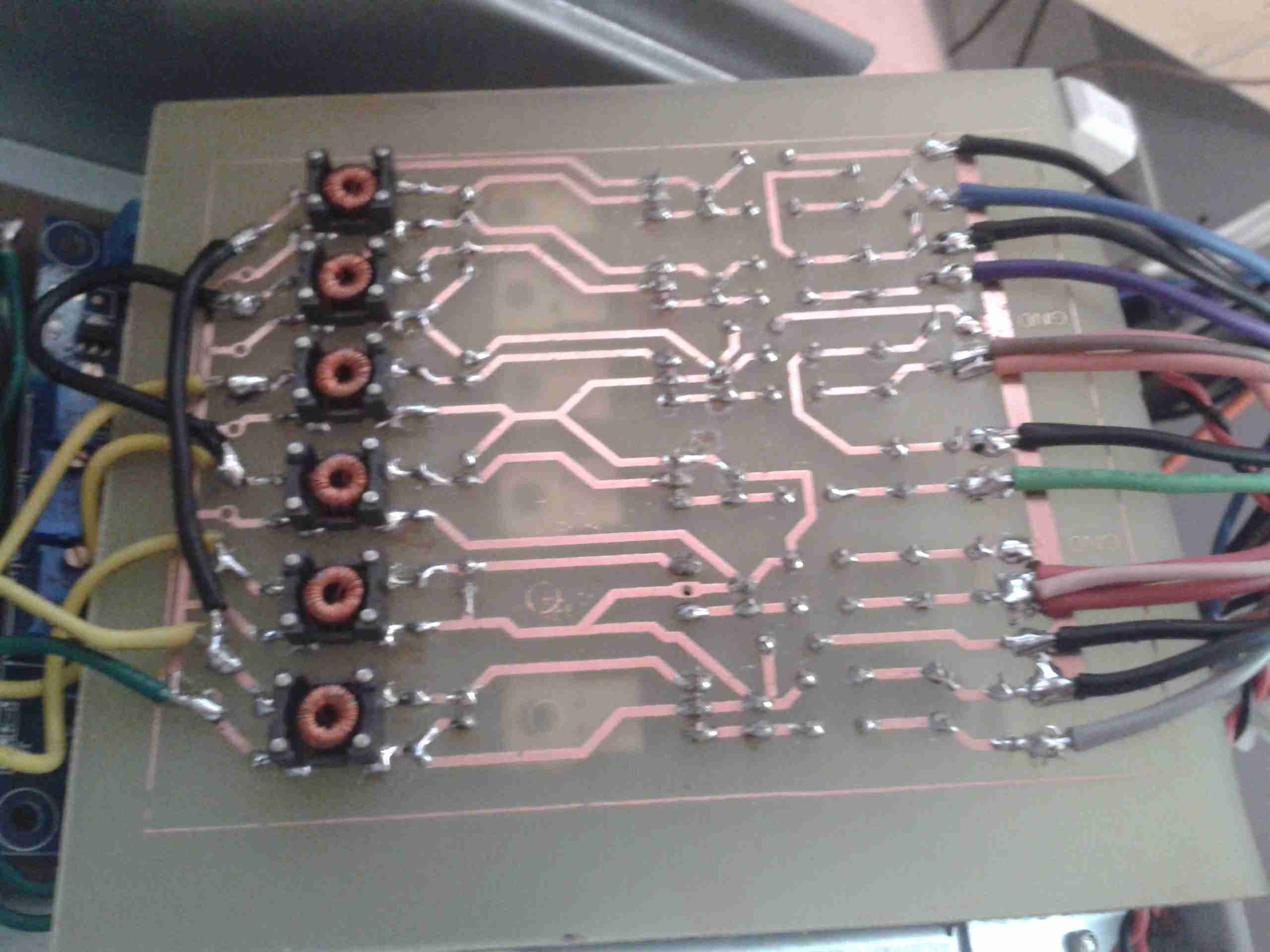
PCB Bottom
Here’s the bottom of the PCB, with the common mode input chokes. The design of this board has allowed me to remove a couple of the switching modules as well, as I can use a single bipolar supply to run both sets of bipolar regulators on this board. This should help remove some of the noise also.
The ripple level has now dropped to lower than it was originally on the mains supply! Current draw at 13.8v DC is about 1.75A.
I’ve had a couple of larger batteries for my UV-5Rs for some time now, and decided to do a quick teardown to see if they’re actually the capacity claimed.
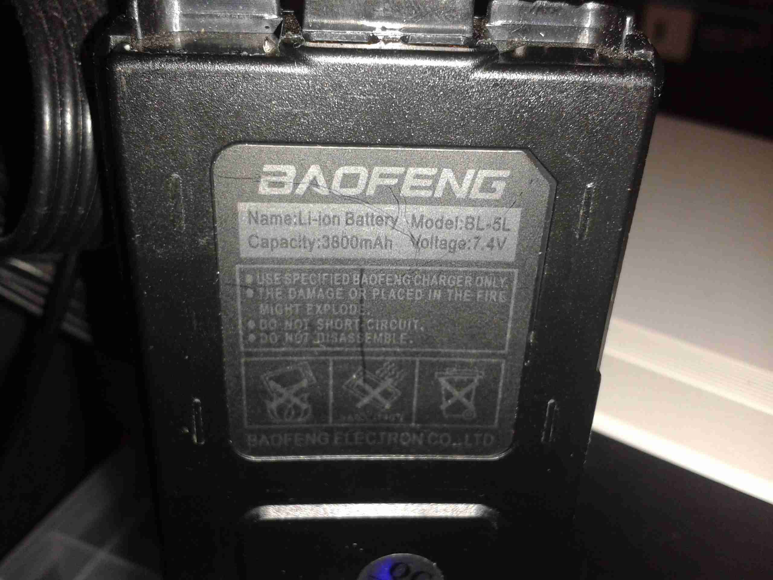
BL-5L Battery
Here’s the label, claiming 3800mAh (3.8Ah) of battery capacity.
These batteries are held together with glue, but a good way to get these kinds of things open is by whacking the seams with the handle of a screwdriver. This cracks the glue without damaging the casing.
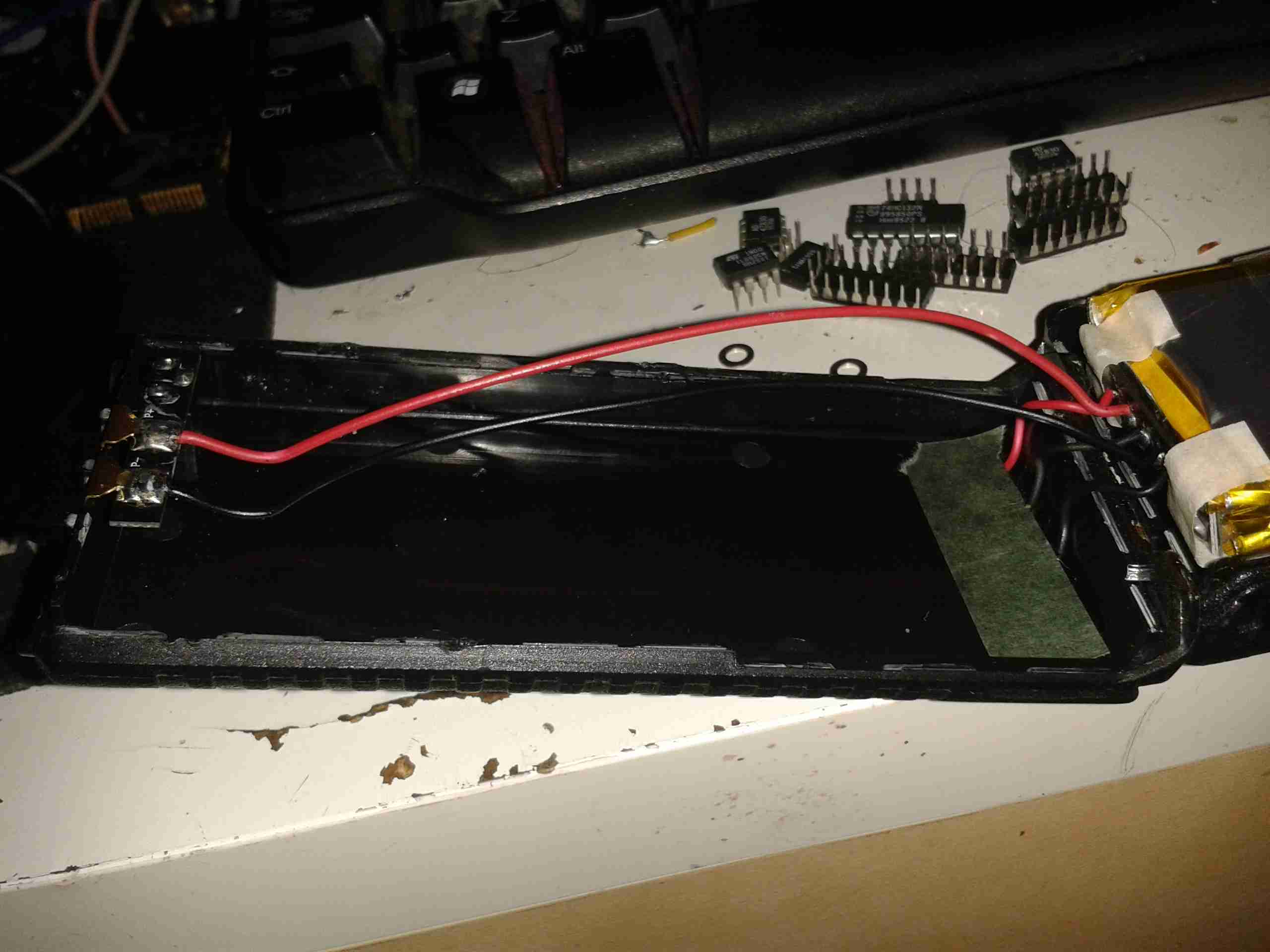
Battery Cracked Open
After a few minutes of cracking the seams, the battery comes right open. The pair of wires link the protection board on the cells to the DC terminals on the top of the pack. The charging terminals are under the cardboard insulator on the right.
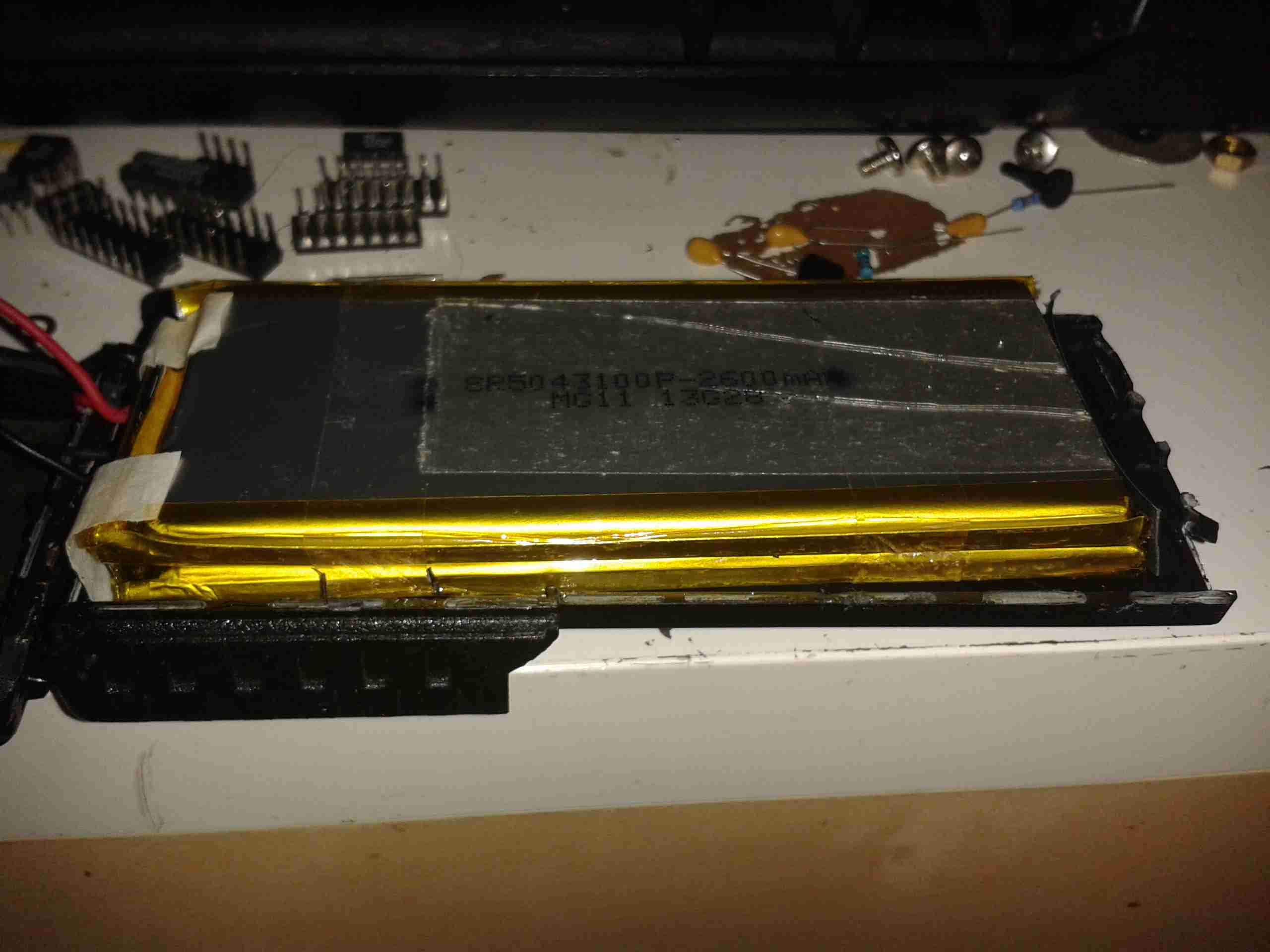
Cells
Here’s the other half of the case, with the cells themselves. These are wired in series for a 7.2v pack, and at a capacity of 2600mAh (2.6Ah) printed on them, the label clearly lies about the capacity.
Since I fitted my scope with a SMPS based 12v input supply, there has been a noise problem on very low volts/div settings, this noise isn’t present on the mains supply, so I can only think it’s coming from the switching frequencies of the various DC-DC modules I’ve used.
Scope Ripple
Because of this I’ve designed a linear post-regulation stage for the supply, to remove the RFI from the DC rails.
This board takes the outputs from the DC-DC converters, removes all the noise & outputs clean DC onto the mainboard of the scope.
As the scope internally uses regulation to get the voltages lower, I’ve found that I don’t have to match the outputs of the mains supply exactly, for the +/-17.5v rails, 12v is perfectly fine instead.
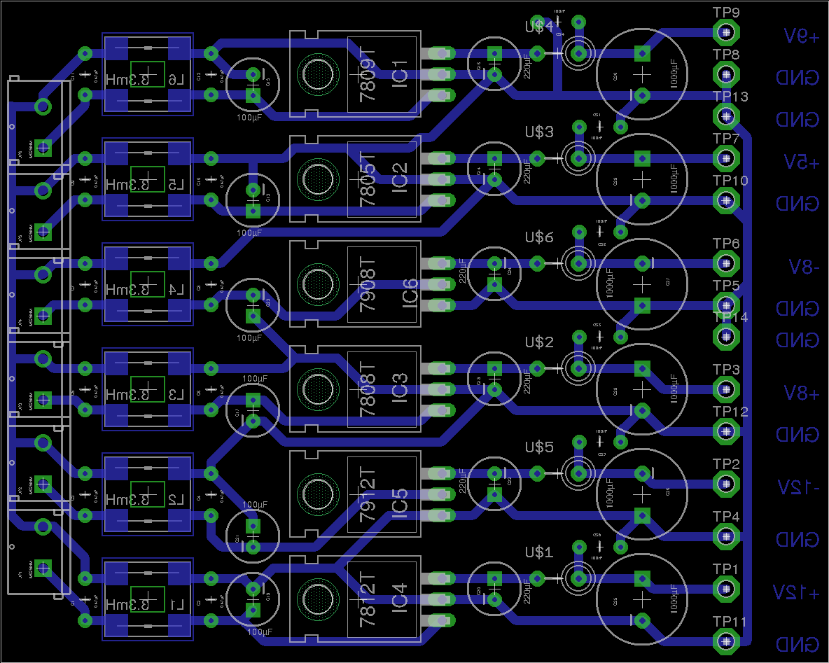
Scope Linear PSU
Here’s the PCB layout, with the 6 common mode filters on the input (left), linear regulator ICs in the centre & the output filters on the right.
Scope Linear PSU
Here’s the schematic layout, as usual the Eagle Project files are in the link below, I’ll update when I have built the board & tested!
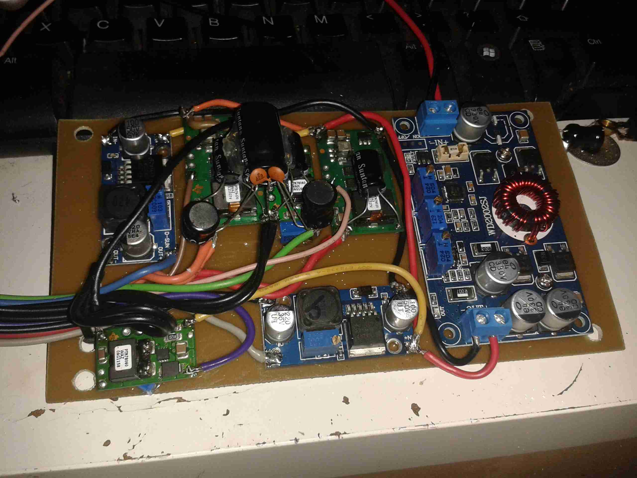
All of the parts I required to complete the supply arrived this morning. After several hours of building, here’s what I came up with:
12v Power Supply
I’ve mounted everything on a piece of FR4 PCB, with it’s copper plane grounded to the case. This backing board is the same size as the original PSU PCB to allow it to be screwed into the same location in the scope.
The power comes in via the converter on the right, which outputs a single 24v rail for the rest of the supplies. The other 6 supplies then generate the individual voltage rails that the scope requires. The use of a single input supply allows this system to operate at voltages up to 30v DC, so it’s good for both 12v & 24v systems.
Scope Ripple
At present the only issue is with some ripple on one of the supplies, this is showing up on the scope display with no input connected at the lowest volts/division. Parts are on order from Farnell to build some common mode filters to remove this from the DC output.
On a 13.8v supply, the scope draws about 1.5A total from the supply, giving a total power consumption of 20.7W. This is with all 4 channels enabled.
My wiring assignments & DC-DC converter ratings are in the table below
Connector Pin
PCB Pin
Signal
Mainboard
DC-DC Rating
Wire Colour
1
10
GND
GND
N/A
BLACK
2
2
+9v_GND
FAN --
NA
BLACK
3
8
+7.5V
6.3V
6A
ORANGE
4
14
-7.5V
-7.5V
2A
GREEN
5
1
NOT USED
AC_TRIG
N/A
NOT USED
6
4
+5V
5V5A
6A
RED
7
6
GND
GND
N/A
BLACK
8
7
GND
GND
N/A
BLACK
9
12
-17.5V
-17.5V
3A
PURPLE
10
9
+7.5V
6.3V
6A
ORANGE
11
3
+9V
FAN +
1A
GREY
12
11
17.5V
17.5V
3A
BLUE
13
5
+5V
5V5A
6A
RED
14
13
GND
GND
N/A
BLACK
Stay tuned for the final section of this build with the power supply filtering & main DC input connections!
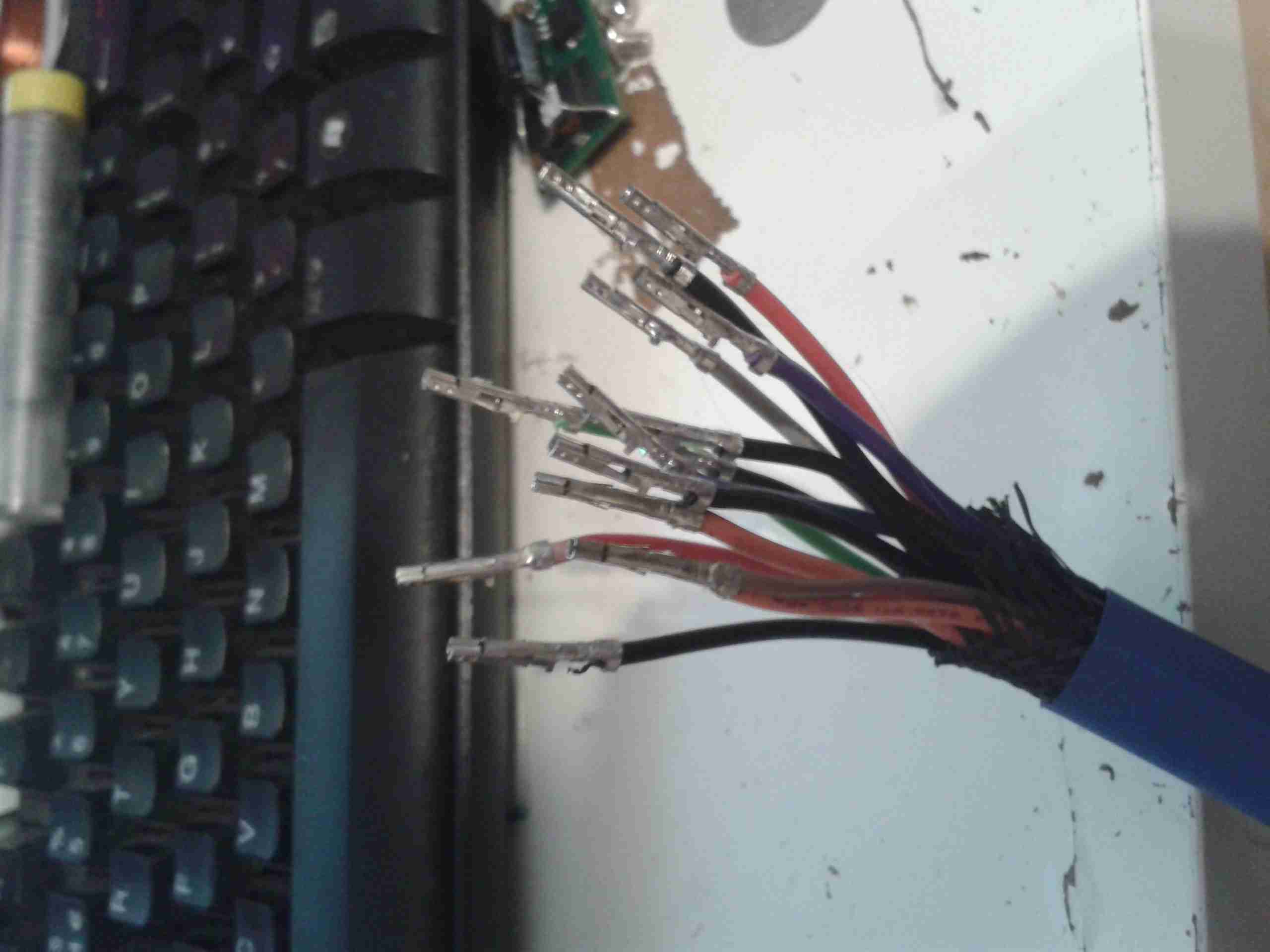
As the crimp tool for the PSU connector in the Rigol scope is a very expensive piece of hardware, I decided to use pre-crimped terminals, from an ATX power connector. (They’re the same type).
Wiring Loom
Here’s the partially completed loom, with the 13 cores for the power rails. The 14th pin is left out as that is for AC triggering, and this won’t be usable on a low voltage supply.
A couple of the pins have two wires, this is for voltage sensing at the connector to compensate for any voltage drop across the cable. The regulators I am using have provision for this feature.
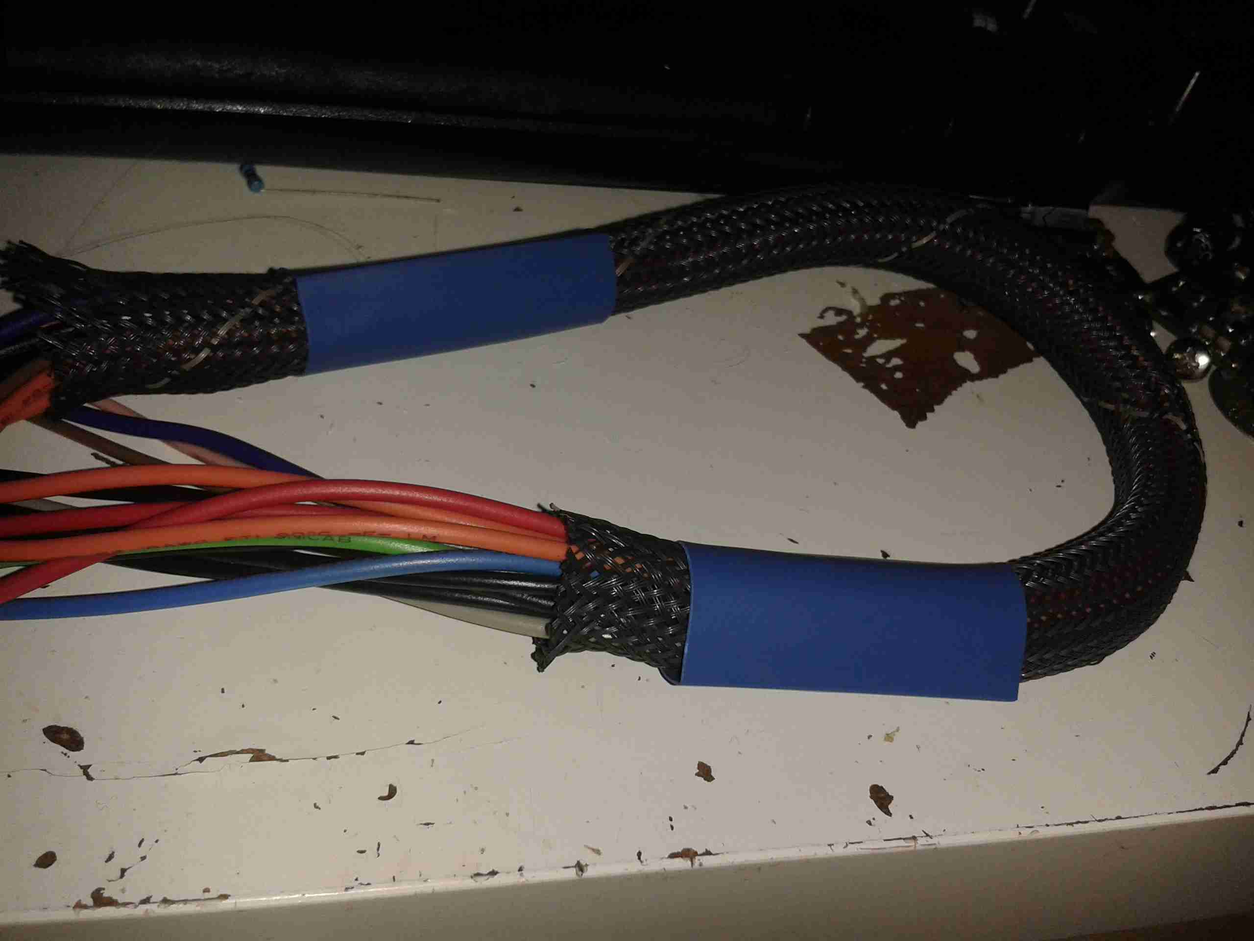
Sleeving
To keep the wiring tidy, I dug a piece of braided loom sleeving out of the parts bin, this will be finished off with the heatshrink once the pins are inserted into the connector shell.
The remaining parts for the loom have been ordered from Farnell & I expect delivery tomorrow.
Here’s some testing of the first bipolar supply for the Rigol scope. This is the +/-7.5v supply.
Bipolar Supply
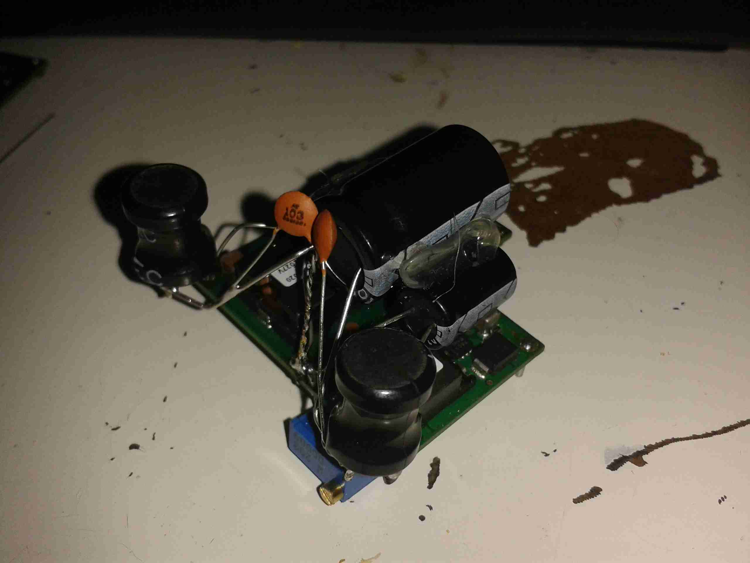
Above is the supply built with it’s output filtering. The modules used are a PTN78020W for the positive rail & a PTN78060A for the negative rail.
Under a 1A load across the total 15v output, here’s some scope traces of the ripple on the supply:
+7.5v Rail
Here’s the ripple on the +7.5v rail of the supply, there’s about 75mV of total ripple.
-7.5v Rail
And here’s the -7.5v rail, the ripple on this is slightly lower, at about 50mV. This should be more than satisfactory as the scope has onboard linear regulation after the switching supply.
While searching around for regulators to convert my new scope to 12v power, I remembered I had some DC-DC modules from Texas Instruments that I’d got a while ago. Luckily a couple of these are inverting controllers, that will go down to -15v DC at 15W/3A capacity.
I’ve had to order a new module from TI to do the -17v rail, but in the meantime I’ve been getting the other regulators set up & ready to go.
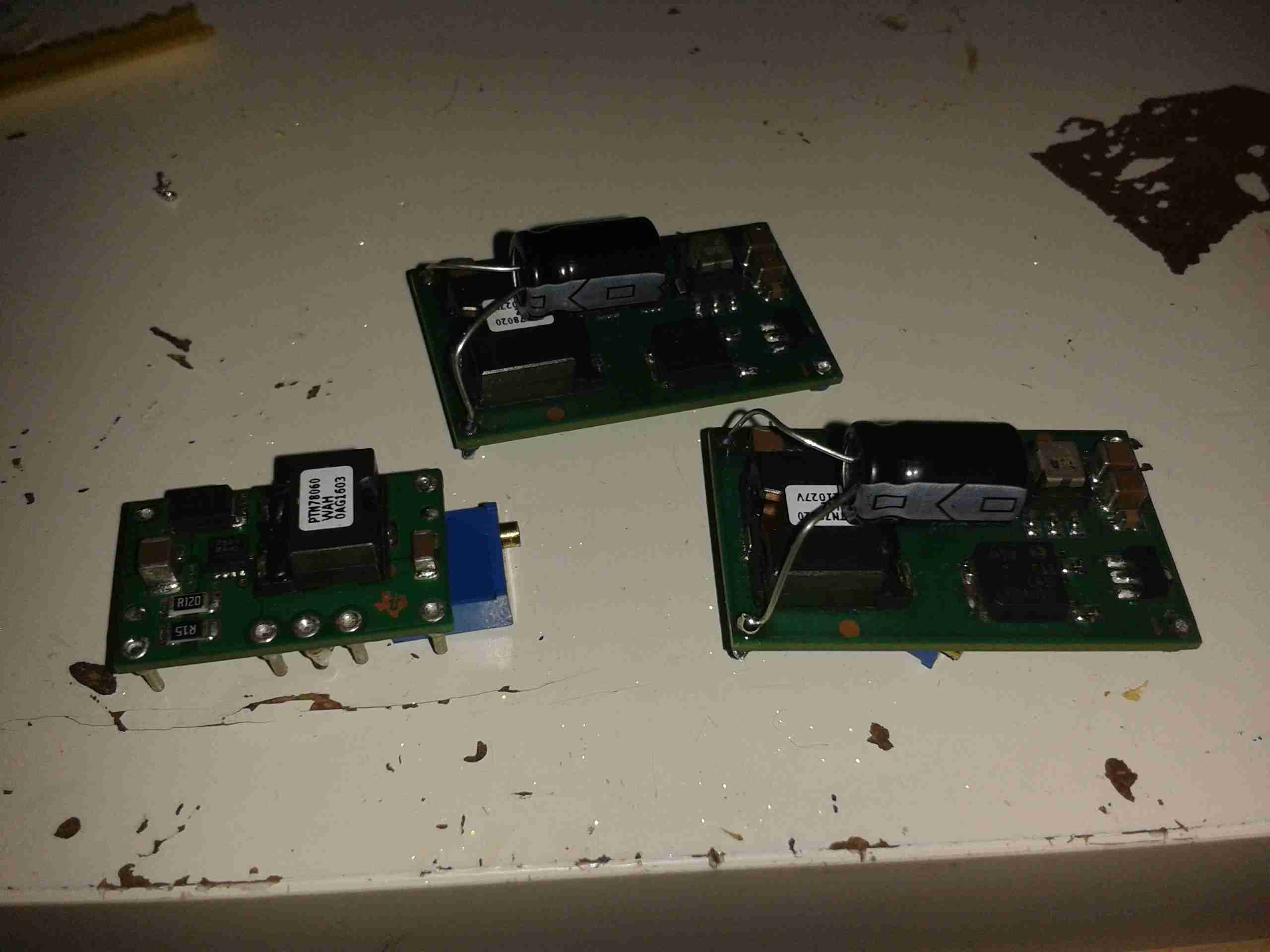
The DC-DC module I’ve got for the -7.5v rail is the PTN78060A type, and the +7.5v & +5v rails will be provided by the PTN78020W 6A buck regulators.
These regulators are rated well above what the scope actually draws, so I shouldn’t have any issues with power.
DC-DC Modules
Here’s the regulators for the 5v, 7.5v & -7.5v rails, with multiturn potentiometers attached for setting the voltage output accurately. I’ve also attached a couple of electrolytics on the output for some more filtering. I’ll add on some more LC filters on the output to keep the noise down to an absolute minimum. These are set up ready with the exact same output voltage as the existing mains AC switching supply, when the final regulator arrives from TI I will put everything together & get some proper rail readings.
There won’t be a proper PCB for this, as I don’t have the parts in Eagle CAD, and I simply don’t have the energy to draw them out from the datasheets.
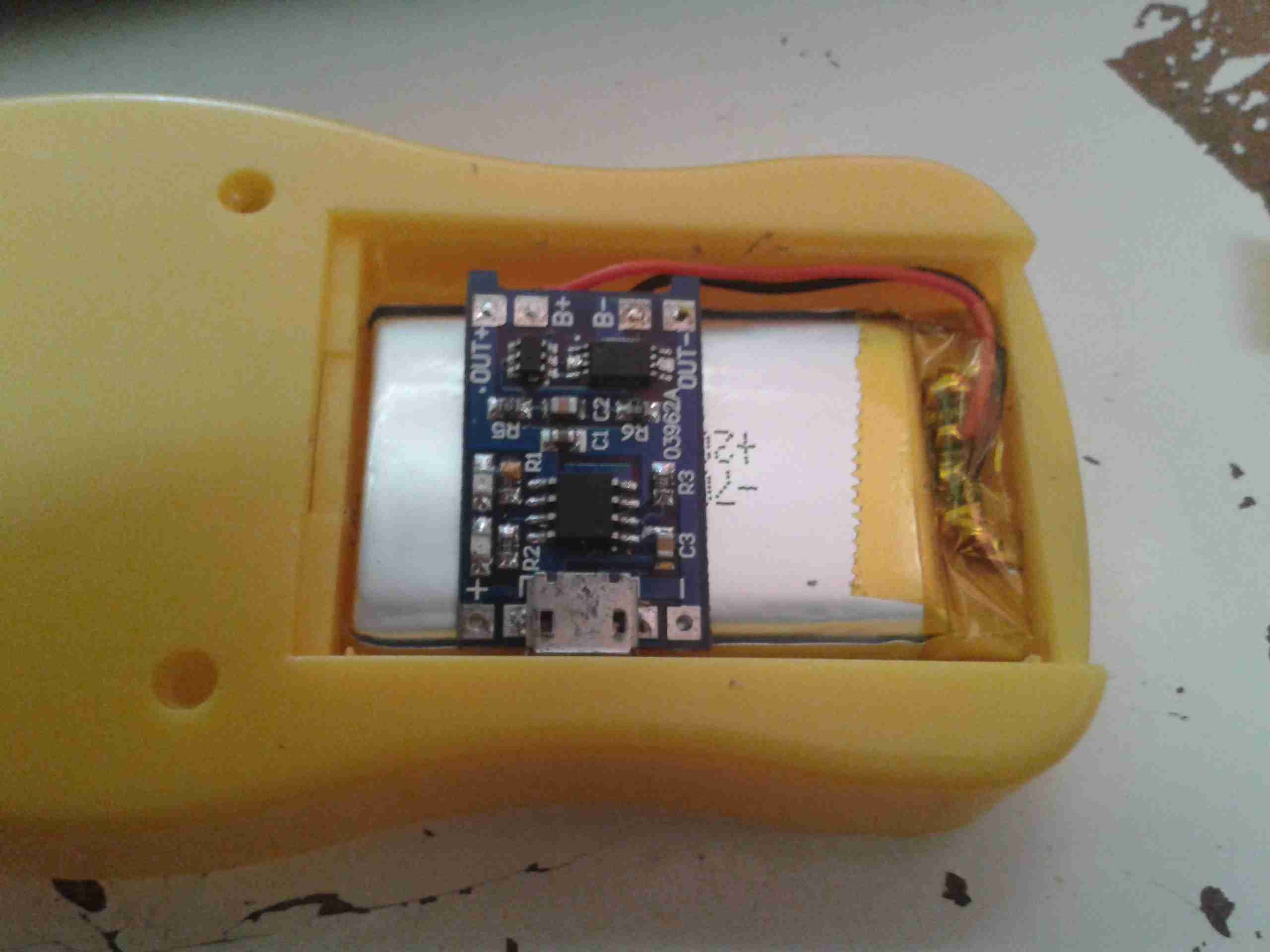
From the factory, the GY561 meter uses alkaline AAA cells for power. As these are not rechargable, and I don’t carry any other devices that take such batteries, I figured I’d replace them with a single Lithium Polymer cell that I can charge via USB.
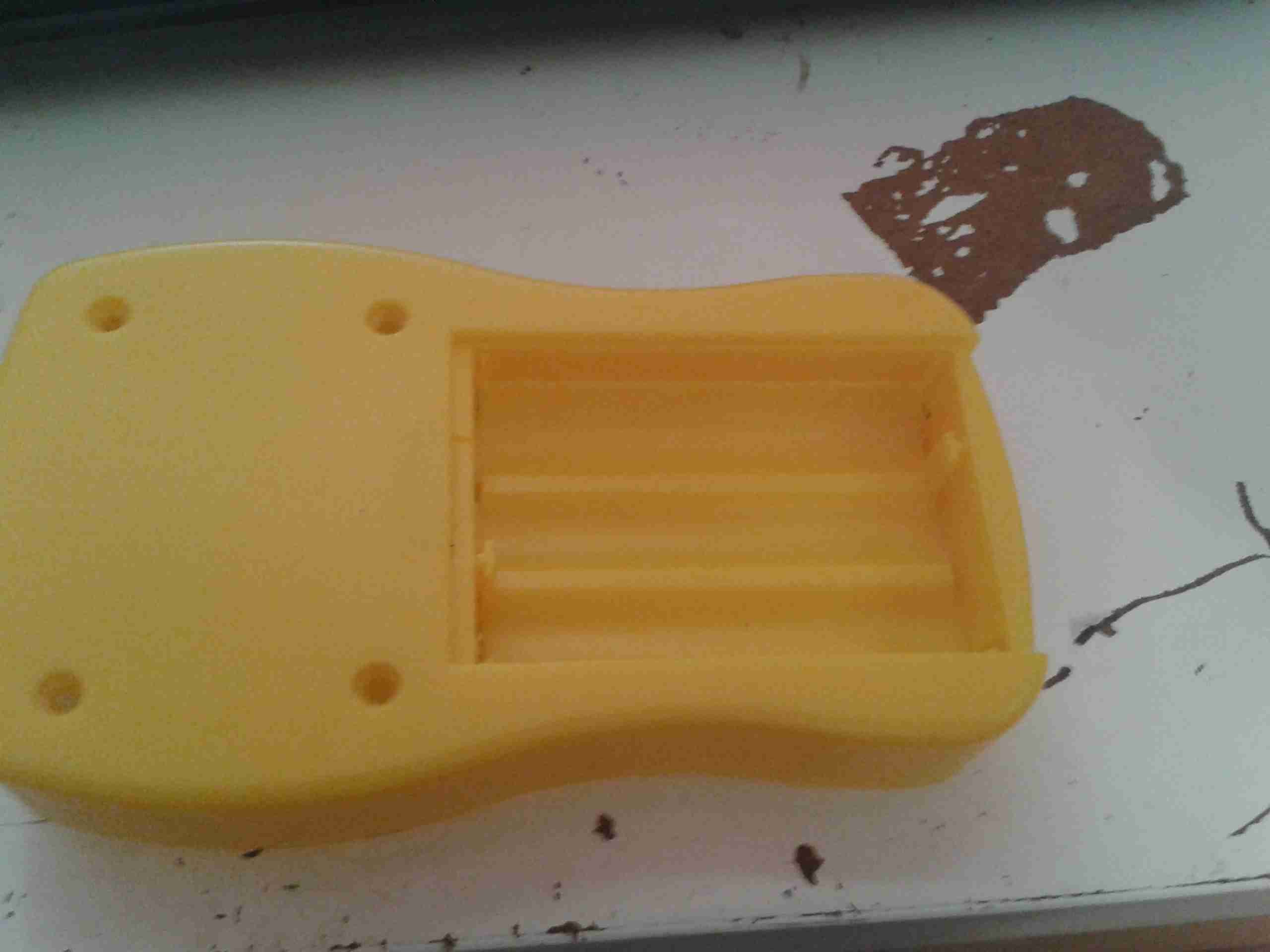
Battery Compartment
Here’s the battery compartment, with the original spring terminals removed.
I searched eBay for a suitable sized cell, and settled on a 1000mAh type, with dimensions of 47mm x 28mm x 7mm.
This size cell required a small amount of modification to the battery compartment to make it fit properly with the associated charge & protection circuitry.
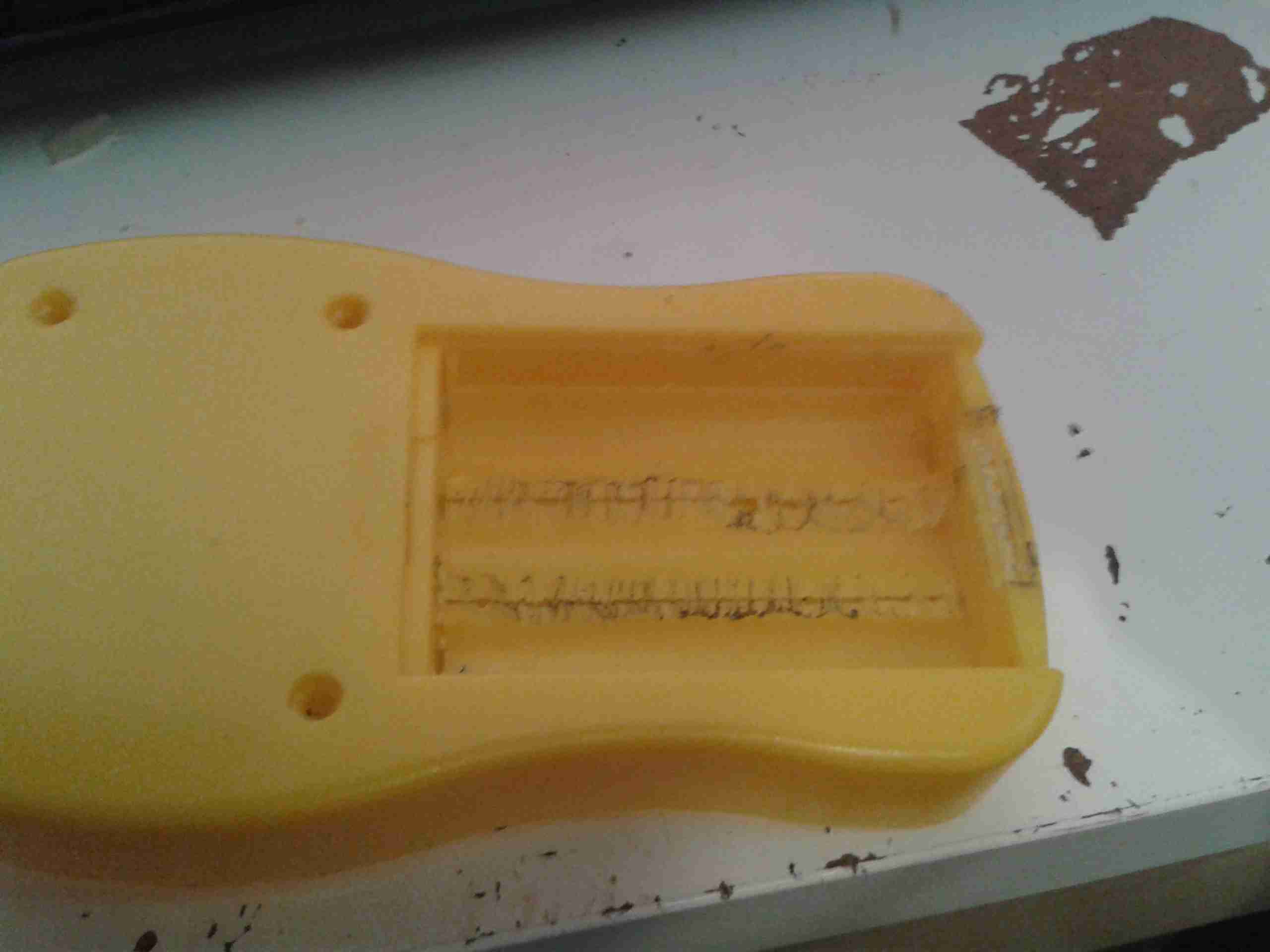
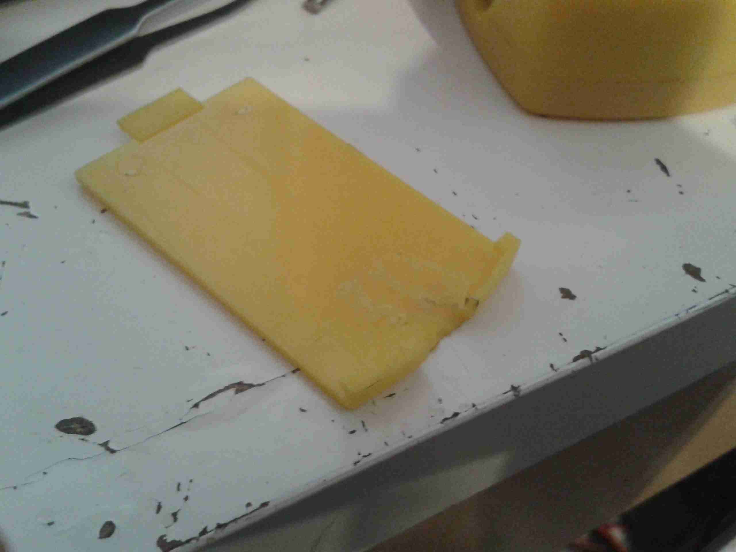
Modified Compartment
Here’s the modifications made to the compartment, I’ve ground away the plastic to make the bottom flat, and the plastic tabs that retained the original spring terminals.
Modifications
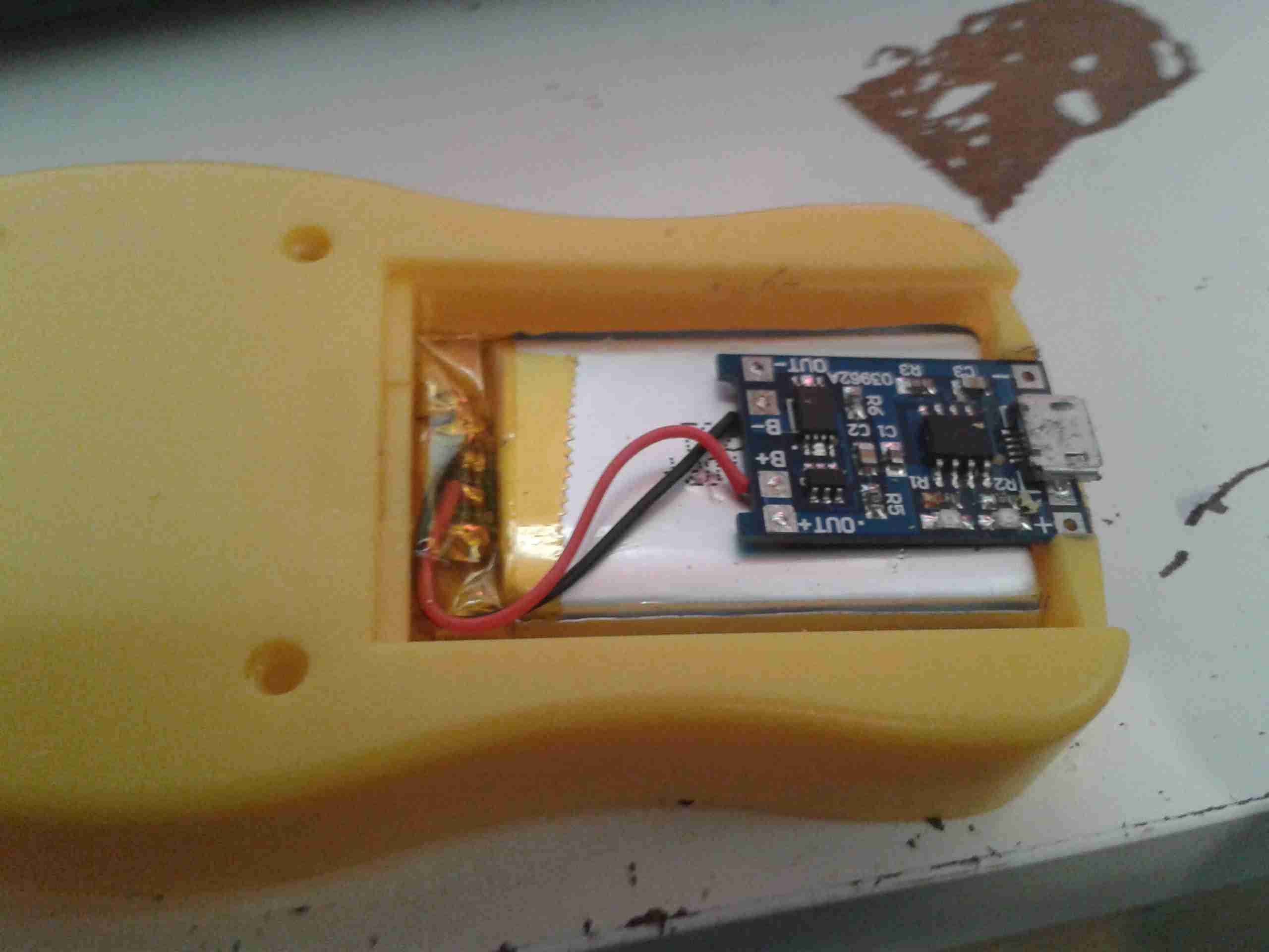
After grinding away the original battery spring holders with a dremel, the cell fits perfectly in the available space. The small PCB on the top of the cell is the USB charger & protection.
Charger
The charger is located in a slot cut in the bottom of the casing, so the USB port is accessible from outside the compartment.
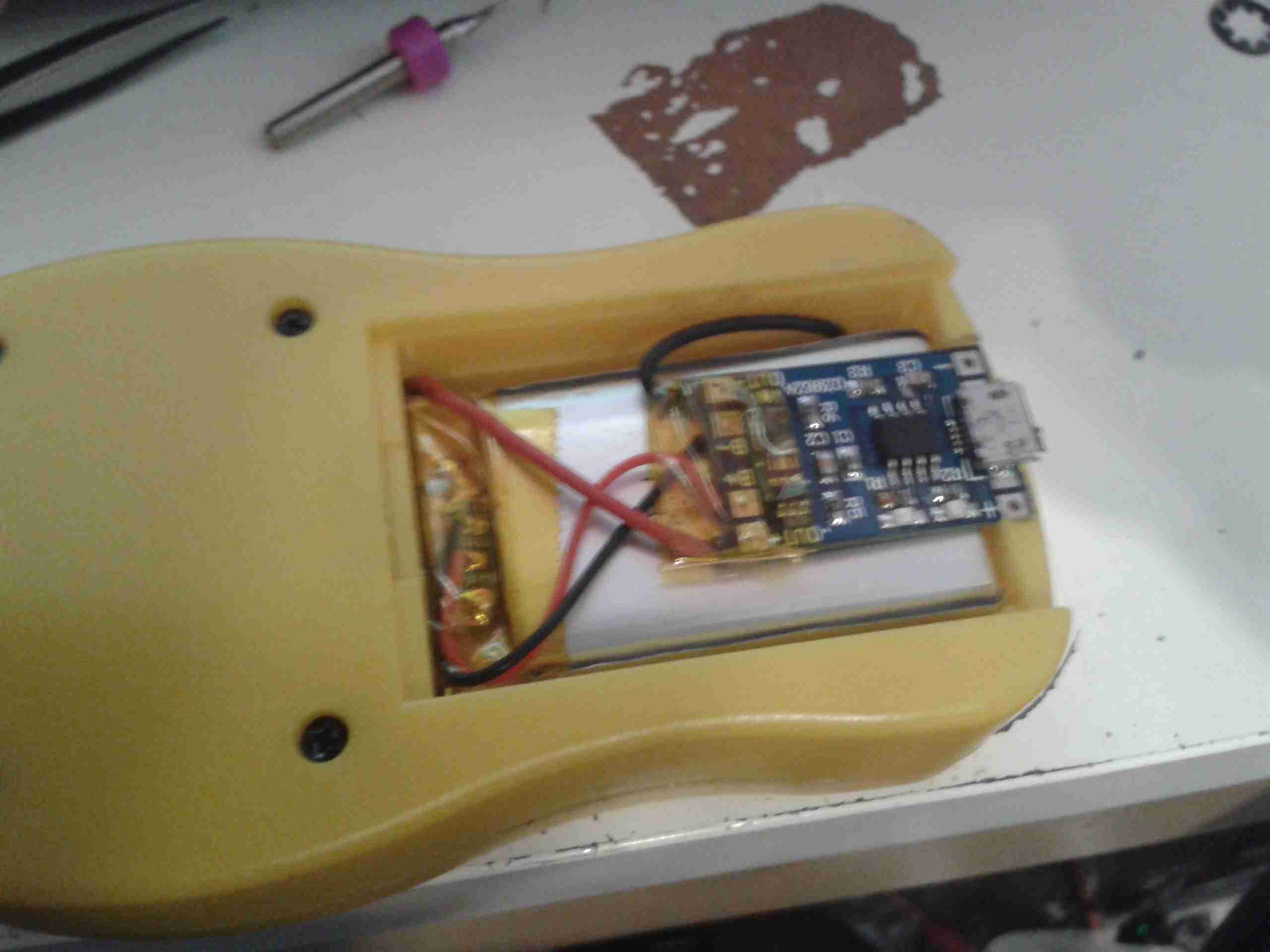
Wiring
Here’s the rest of the wiring completed, with the power wires going through holes in the bottom of the battery compartment to join onto the PCB where the original terminals were located. I have insulated the solder joints on the control PCB with some Kapton tape to prevent any shorts against the lithium cell.
Battery Cover
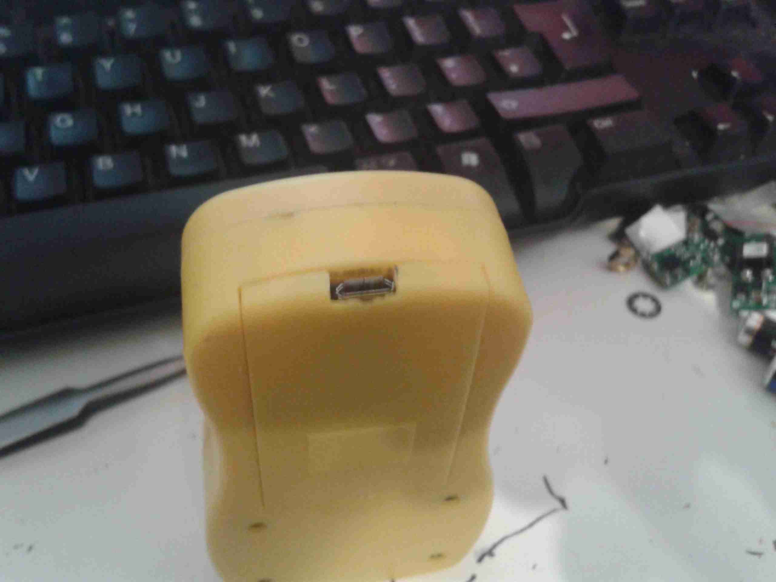
A small cutout was also required in the battery cover to allow the USB connector to poke out. This was easy to do on the soft plastic with a Dremel tool.
Charging Port
With the battery cover installed, the USB port is nicely recessed into the edge.
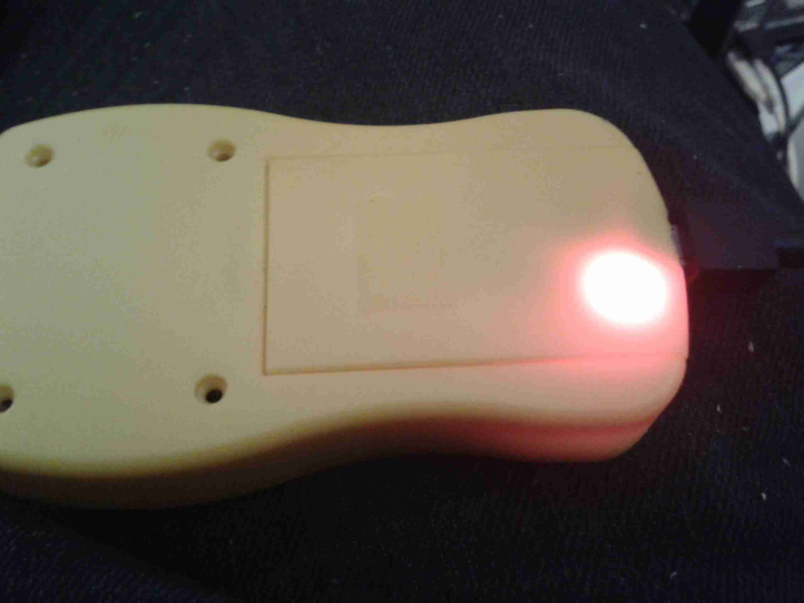
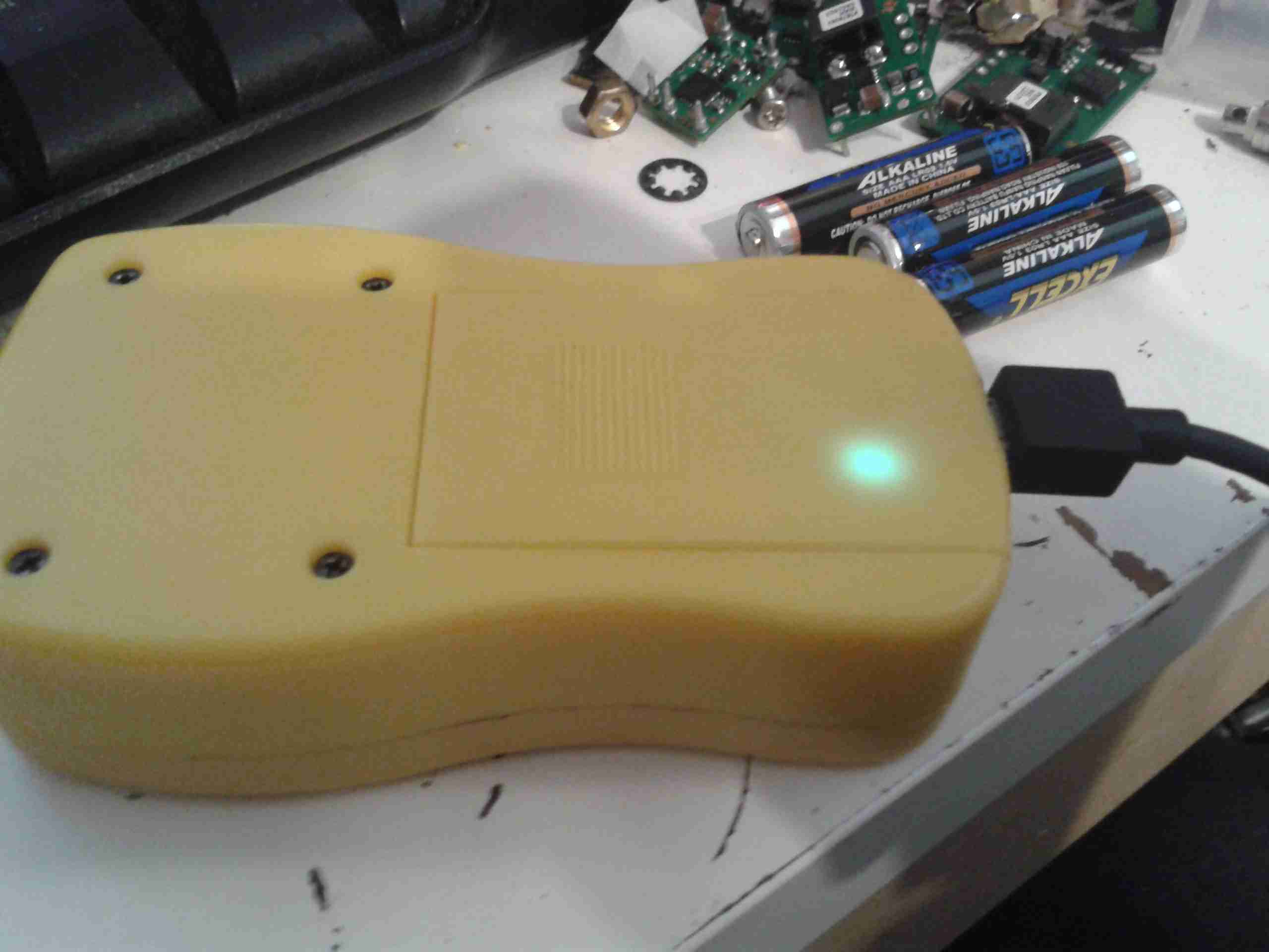
Charging LED
The indicator LEDs on the charging & control board show nicely through the plastic, here’s the unit on charge. When the charge is complete, another LED lights as shown below.
The boat being over 50 years old, there are some parts that are suffering from rather bad corrosion. The bow deck plate is about the worst, so this is being replaced in it’s entirety.
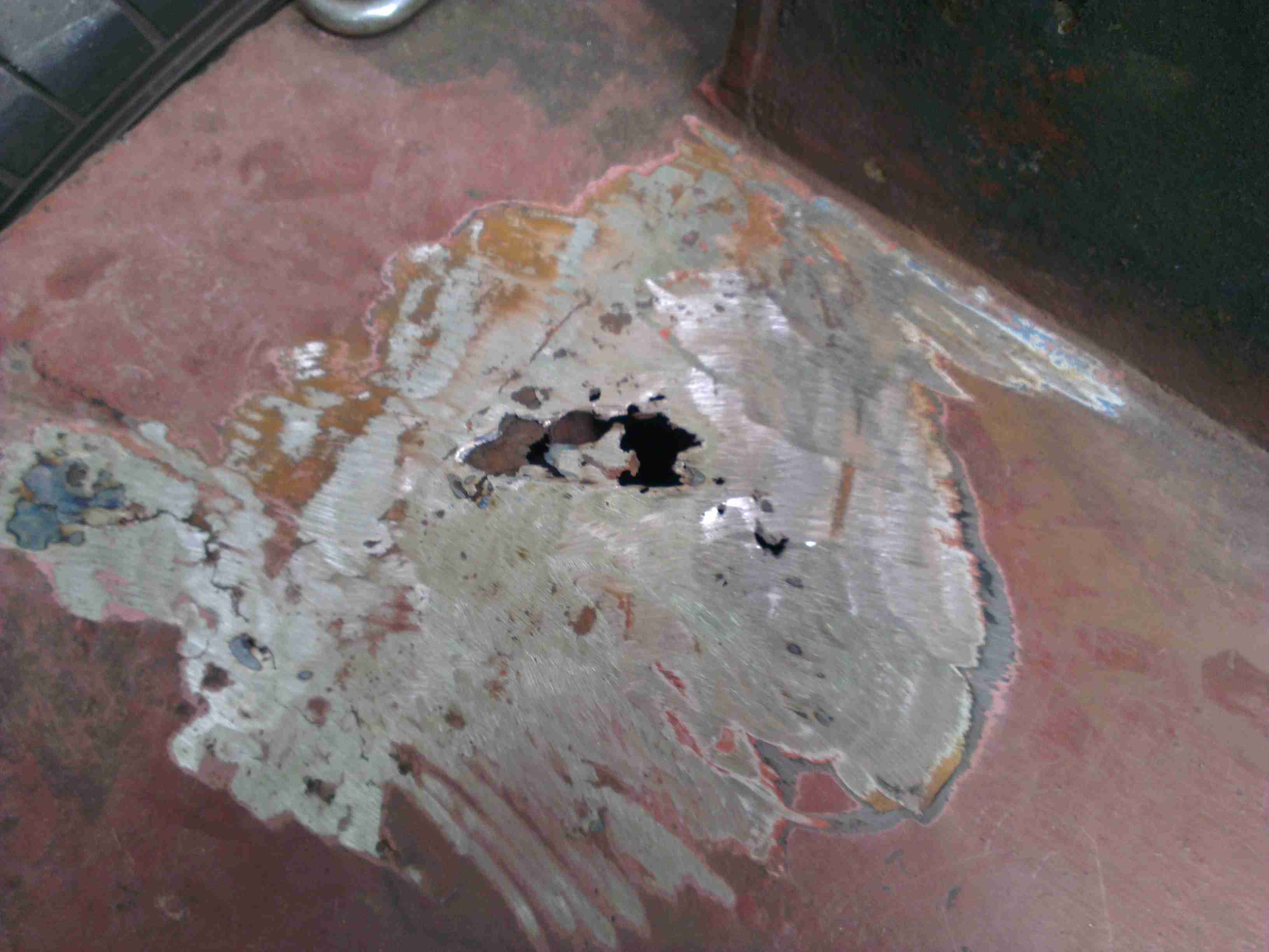
However a hole has developed in the stern deck, this has rusted from the inside out due to condensation in the engine bay.
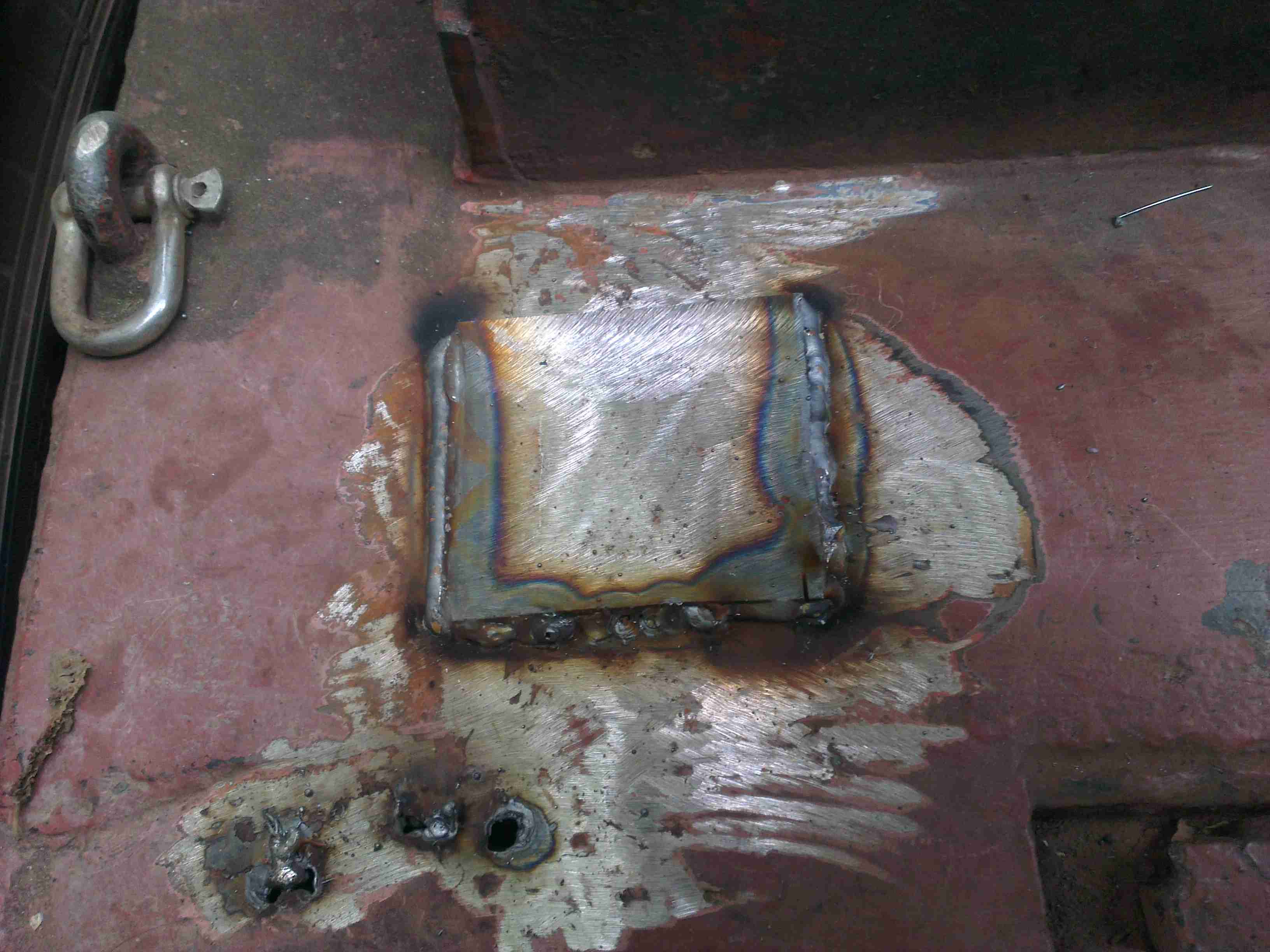
After Grinding
After taking a grinder to the area, this is how it looks. The steel has gone from 1/4″ to paper thin, not surprising after 50 years or so!
It would be a massive job to cut out the entire plate for replacement, so a patch was made from 5mm steel, and welded over the hole:
Patch
Here’s the patch partially welded. The holes closer to the bottom are another small area of damage, and another patch will have to be cut for this. It’s covering the deck drain channel so it’s frequently under water, so it’s inevitable that this section would corrode.
All that is left to do now is to finish off the welding, grind everything smooth & repaint.
Alas, my old trusty Hameg HM303 30MHz oscilloscope has finally died. I’ve had this scope for many years, an eBay buy when I noticed they were going cheap.
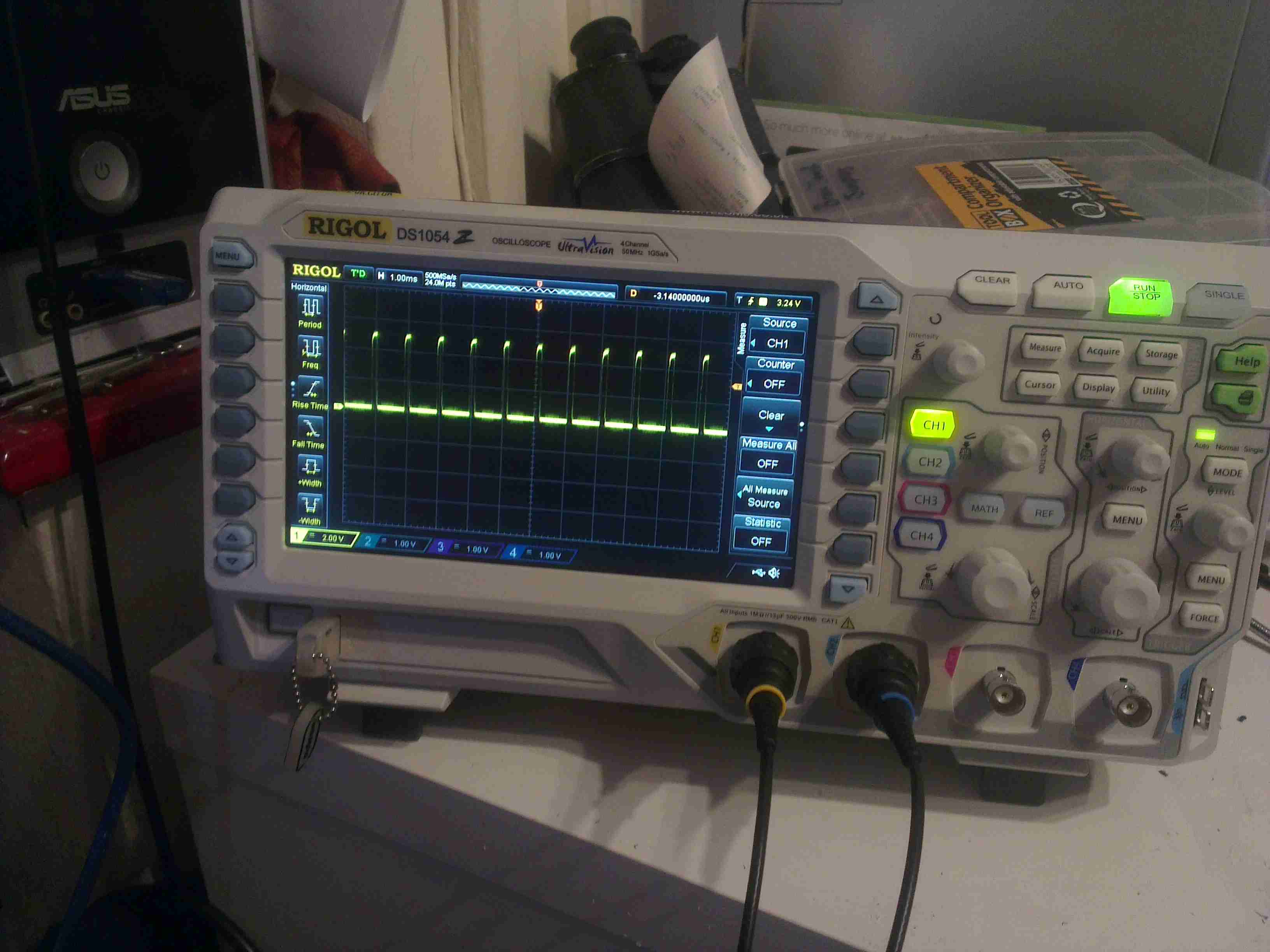
It’s been replaced with a brand new Rigol DS1054Z, a 4-channel 50MHz DSO.
Scope
This is a big jump from the old analogue CRT scope I was using, it’s certainly going to be a steep learning curve!
System Info
I chose this scope through the help of the EEVBlog & it’s associated forums. Through this I discovered that I could upgrade the scope with a key to enable some extra features! In the above screenshot, the key has been applied, and the model number now shown is the DS1104Z.
This is the next scope up in the model chain, with many more triggering options, serial decoders, higher memory depth, recording & 100MHz bandwidth. While I rarely need to measure anything higher than in the kHz range, these options will definitely come in useful! The list of installed options is below:
Installed Options
And now for some sample waveforms, the scope has the option to save screenshots to USB flash disks, so when I make posts with waveforms in the future, the need to photo the screen of the scope is gone!
I recently dug out my other card printer to fit it with a 12v regulator, (it’s 24v at the moment), and figured I’d do a teardown post while I had the thing in bits.
This is a less industrial unit than my Zebra P330i, but unlike the Zebra, it has automatic duplexing, it doesn’t have Ethernet connectivity though.
Unlike domestic printers, which are built down to a price, these machines are very much built up to a spec, and feature some very high quality components.
Naked Printer
Here’s the mechanism with the cowling removed. This is the main drive side of the printer, with the main drive stepper at left, ribbon take-up spool motor lower right, and the duplex module stepper motors at far right.
Main Motor Drive
The main drive motor runs the various rollers in the card path through a pair of synchronous belts, shown here.
Main Stepper
The stepper itself is a quality ball-bearing Sanyo Denki bipolar motor.
Main Stepper Driver
Electrical drive is provided to the stepper with a L6258EX DMOS universal motor driver. This chip can also drive DC motors as well as steppers.
Ribbon Supply Spool
Here is the encoder geared onto the ribbon supply spool. This is used to monitor the speed the ribbon is moving relative to the card.
Printer Top
Here’s a top view through the printer, the blue roller on the left cleans the card as it’s pulled from the feeder, the gold coloured spool to it’s right is the ribbon supply reel. The cooling fan on the right serves to stop the print head overheating during heavy use.
Spool Take Up Motor
The spool take-up reel is powered by another very high quality motor, a Buhler DC gearmotor. These printers are very heavily over engineered!
This motor drives the spool through an O-Ring belt, before the gear above. This allows the drive to slip in the event the ribbon jams, preventing it from breaking.
Duplex Unit Stepper Drivers
The pair of steppers that operate the duplexing unit are driven by a separate board, with a pair of L6219DS bipolar stepper driver ICs. There are also a couple of opto-sensors on this board for the output hopper.
Main Control PCB
All the mechanisms of the printer are controlled from this main PCB, which handles all logic & power supply functions. Sections on the board are unpopulated, these would be for the Ethernet interface, smart card programming & magstripe programming.
Main CPU
The brains of the operation is this ColdFire MCF5208CVM166 32-bit microprocessor. It features 16KB of RAM, 8KB of cache, DMA controller, 3 UARTs, SPI, 10/100M Ethernet and low power management. This is a fairly powerful processor, running at 166MHz.
It’s paired with an external 128Mbit SDRAM from Samsung, and a Spansion 8Mbit boot sector flash, for firmware storage.
USB Interface & Power Input
Here the USB interface IC is located. It’s a USBN9604 from Texas Instruments, this interfaces with the main CPU via serial.
Following on from my recent power supply build, I’ve added on a couple of improvements:
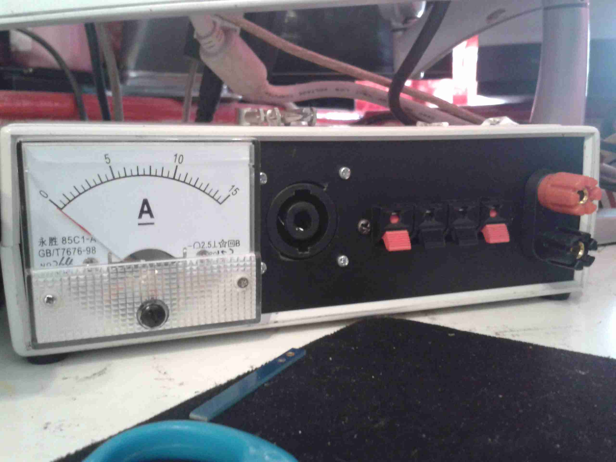
Front Panel
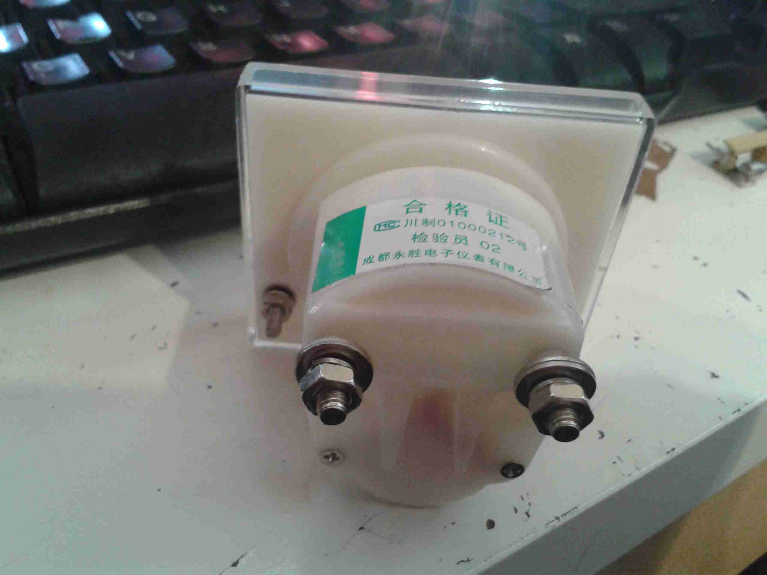
I’ve added on my standard SpeakOn type 30A connector, a bank of push terminals for quick connecting test leads, and a 15A FSD ammeter.
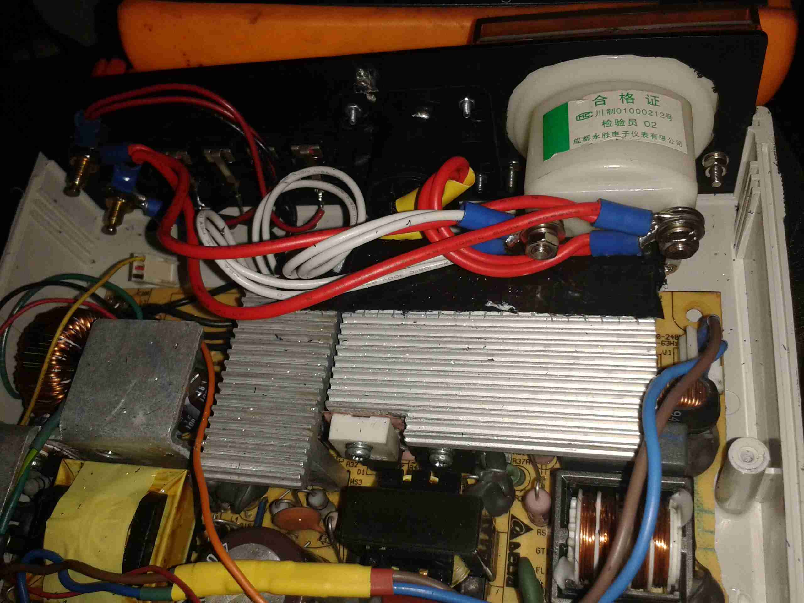
Panel Rear
Due to the limited space inside the supply, I’ve had to improvise some insulation on the mains-side heatsink to prevent a nasty accident. The heatsinks are tied to the supply’s HVDC bus negative, so they are energized at -145v DC relative to mains earth. This fact has given me a nasty surprise! The insulation is several layers of Kapton tape, with a couple of layers of Duct Tape. This along with trirated wire to the SpeakOn & the panel meter should ensure safety.
The Ammeter itself was sourced from eBay, for £2. It seems pretty accurate so far!
Ammeter
The shunt is built into the rear of these meters, in an ultrasonically welded part of the case, so I can’t examine it. Hopefully it is indeed rated to 15A!
The only things left to make this supply complete are a mains power switch, and a fan speed control, as the fan I have used is a little noisy at full speed. It will be good to get the speed based from the internal temperature, so the fan only runs at full speed when the supply is under load.
In my shack, 99% of my gear is all 12v powered, which is good for a few reasons:
Single Power Supply – This increases efficiency, as I’m only getting the losses of a single supply.
Safety – Mains voltages are dangerous, I’m not fond of working on such equipment.
Portability – I can power everything pretty much no matter were I am from a convenient car battery.
Convenience – Since everything is single supply, with all the same plugs, I don’t have to think about what goes where. This is more important due to my forgetfulness ;).
The one piece of equipment I regularly use that isn’t 12v is my soldering station. This is a Maplin A55KJ digital unit, which uses a 24v heating element.
While the soldering wand works OK when hooked direct to a 12v power supply (only at half power though), this removes the convenience of having temperature control.
The circuitry inside the unit is PIC microcontroller based, and doesn’t even bother rectifying the AC from the supply transformer before it’s sent to the heater. Because of this there are several reasons why I can’t just hook a DC-DC converter up to it to give it 24v.
It’s sensing the zero-crossing for the triac switch, to reduce heat dissipation, so it refuses to work at all with DC.
On looking at the Great Google, I found a project on Dangerous Prototypes, an Arduino based PID controller for soldering irons.
This requires that the soldering wand itself contains a thermocouple sensor – as the Maplin one I have is a cheap copy of the Atten 938D, it doesn’t actually use a thermocouple for temperature sensing. It appears to read the resistance of the element itself – Nichrome heating elements change resistance significantly depending on temperature.
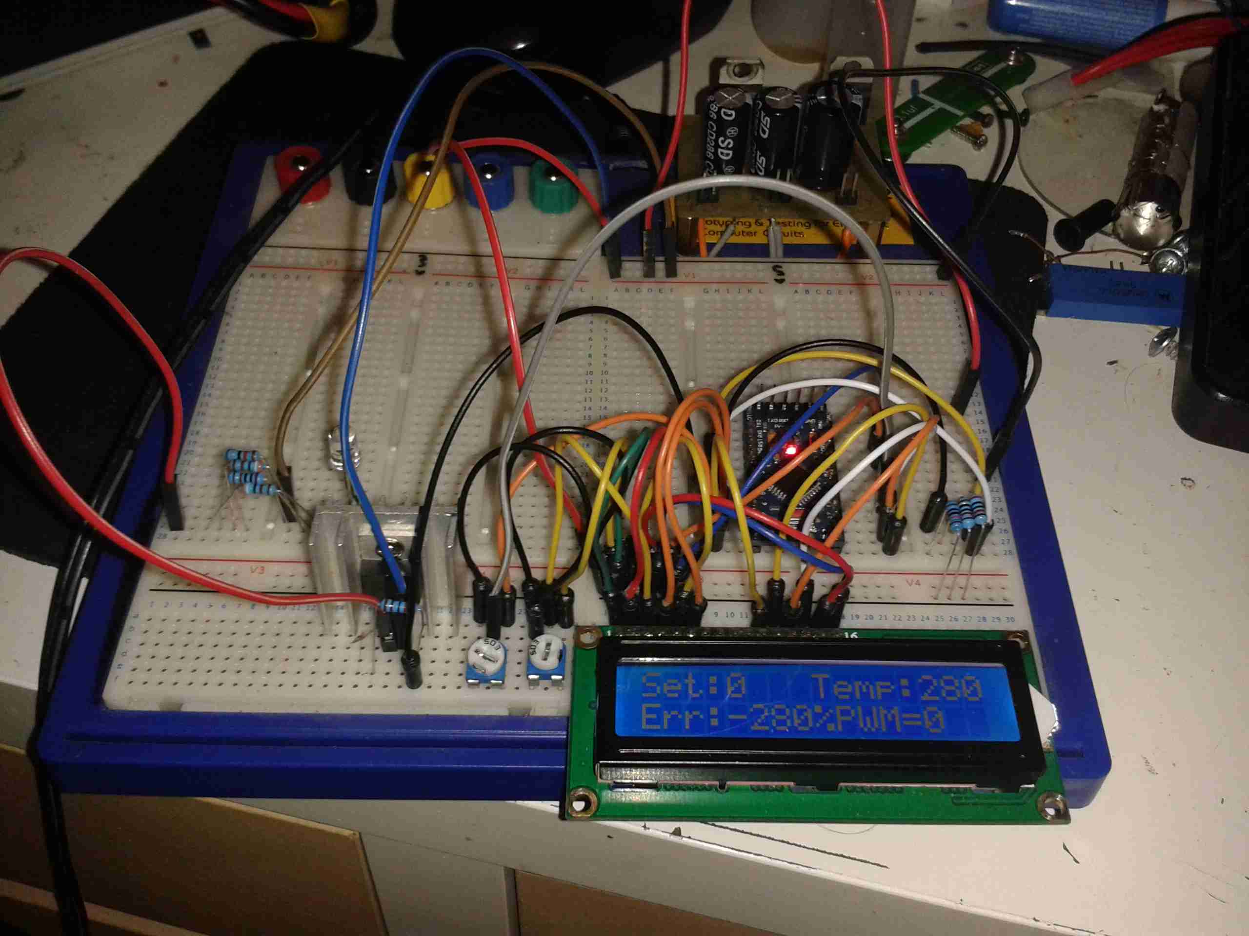
I’ve managed to find a source of cheap irons on eBay, with built in thermocouples, so I’ve got a couple on order to do some testing with. While I wait for those to arrive, I’ve prototyped up the circuit on breadboard for testing:
Prototype
I’ve remapped some of the Arduino pins, to make PCB layout less of a headache, but the system is working OK so far, with manual input for the sensed temperature.
I’m using an IRL520N logic-level HEXFET for the power switching, rated at 10A. As the irons only draw a max of 4.5A, this is plenty beefy enough.
To come up with the +24v supply for the heater, a small DC-DC converter will be used.
More to come when the components for the thermocouple amplifier arrive, and the soldering irons themselves!
A while ago I blogged about modifying the output voltage of some surplus Cisco switch power supplies to operate at 13.8v.
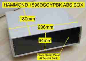
Since I was able to score a nice Hammond 1598DSGYPBK ABS project box on eBay, I’ve built one of the supplies into a nice bench unit.
Hammond ABS CaseSupply Unit
Above is the supply mounted into the box, I had to slightly trim one edge of the PCB to make everything fit, as it was just a couple of mm too wide. Luckily on the mains side of the board is some space without any copper tracks.
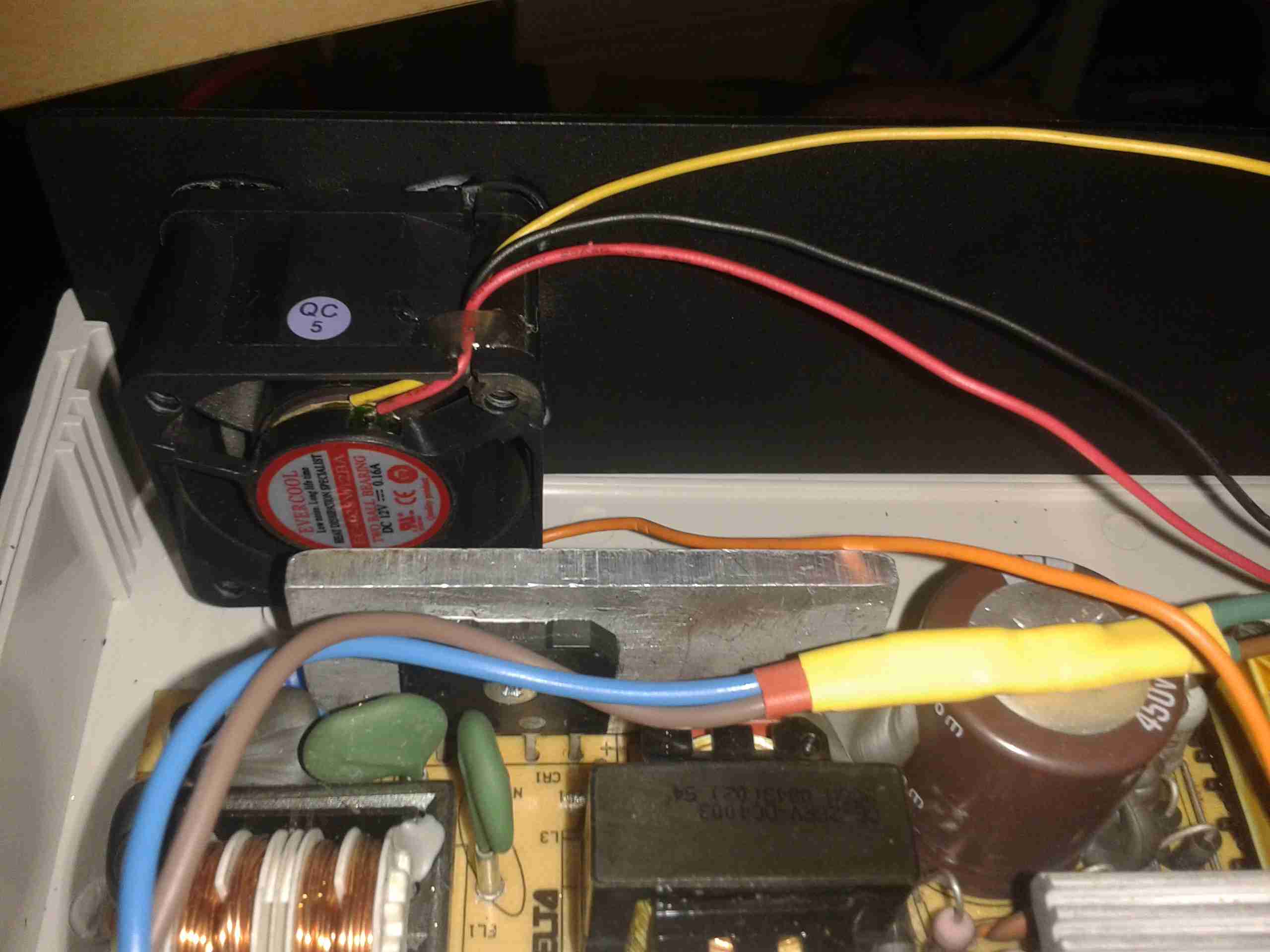
PSU Fan
These supplies are very high quality & very efficient, however they came from equipment that was force-air cooled. Running the PSU in this box with no cooling resulted in overheating. Because of this I have added a small 12v fan to move some air through the case. The unit runs much cooler now. To allow the air to flow straight through the case, I drilled a row of holes under the front edge as vents.
Output Side
Here is the output side of the supply, it uses standard banana jacks for the terminals. I have used crimp terminals here, but they are soldered on instead of crimped to allow for higher current draw. The negative return side of the output is mains earth referenced.
I have tried to measure output ripple on this supply, but with my 10X scope probe, and the scope set to 5mV/Div, the trace barely moves. The output is a very nice & stable DC.
This supply is now running my main radio in the shack, and is small enough to be easily portable when I move my station.
Now the final bits have arrived for the SWR Meter module, I can do the final assembly.
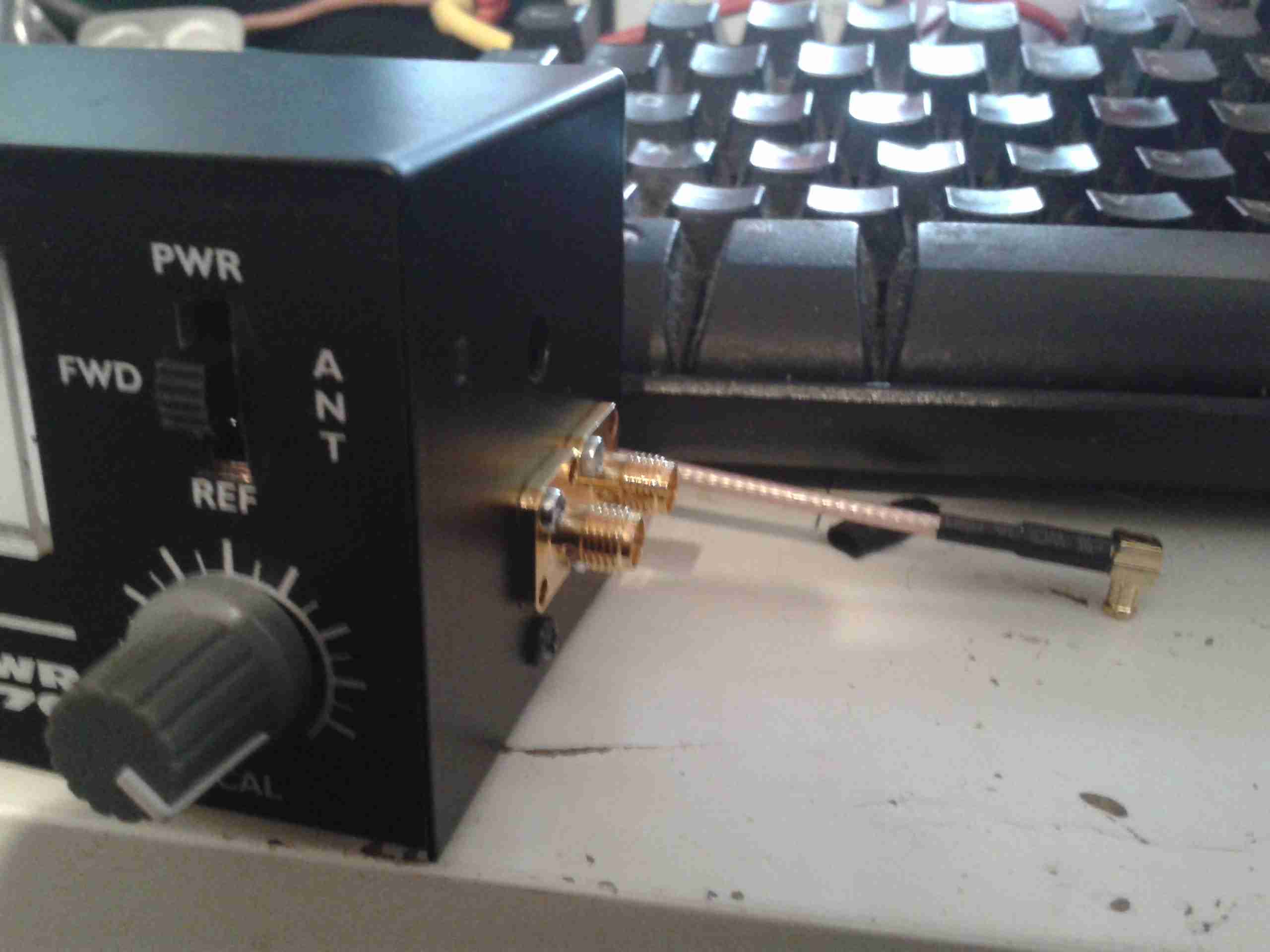
SMA Connectors
Here the SMA connectors are installed on the side of the eBay meter, for forward & reverse power tap.
These are simply tee’d off the wiring inside the meter where it connects to the switch.
Uncalibrated
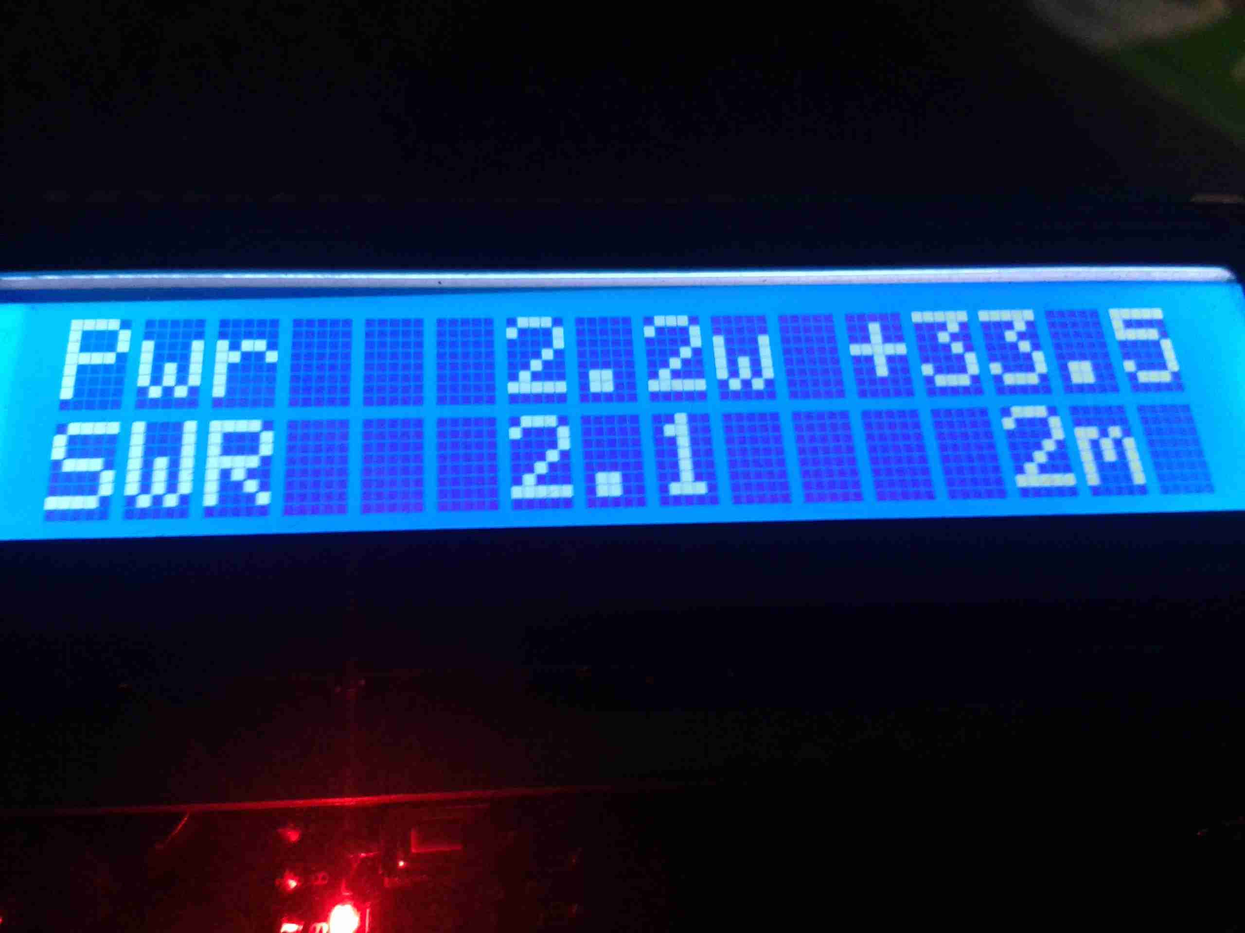
The meter is connected to the module via a pair of RG58 SMA leads, above is a readout before calibration, using one of my Baofeng UV-5Rs.
I’m using my GY561 eBay Power Meter as a calibration source, and as this isn’t perfect, the readings will be slightly off. If I can get my hands on an accurate power meter & dummy load I can always recalibrate.
Tools are only as accurate as the standard they were calibrated from!
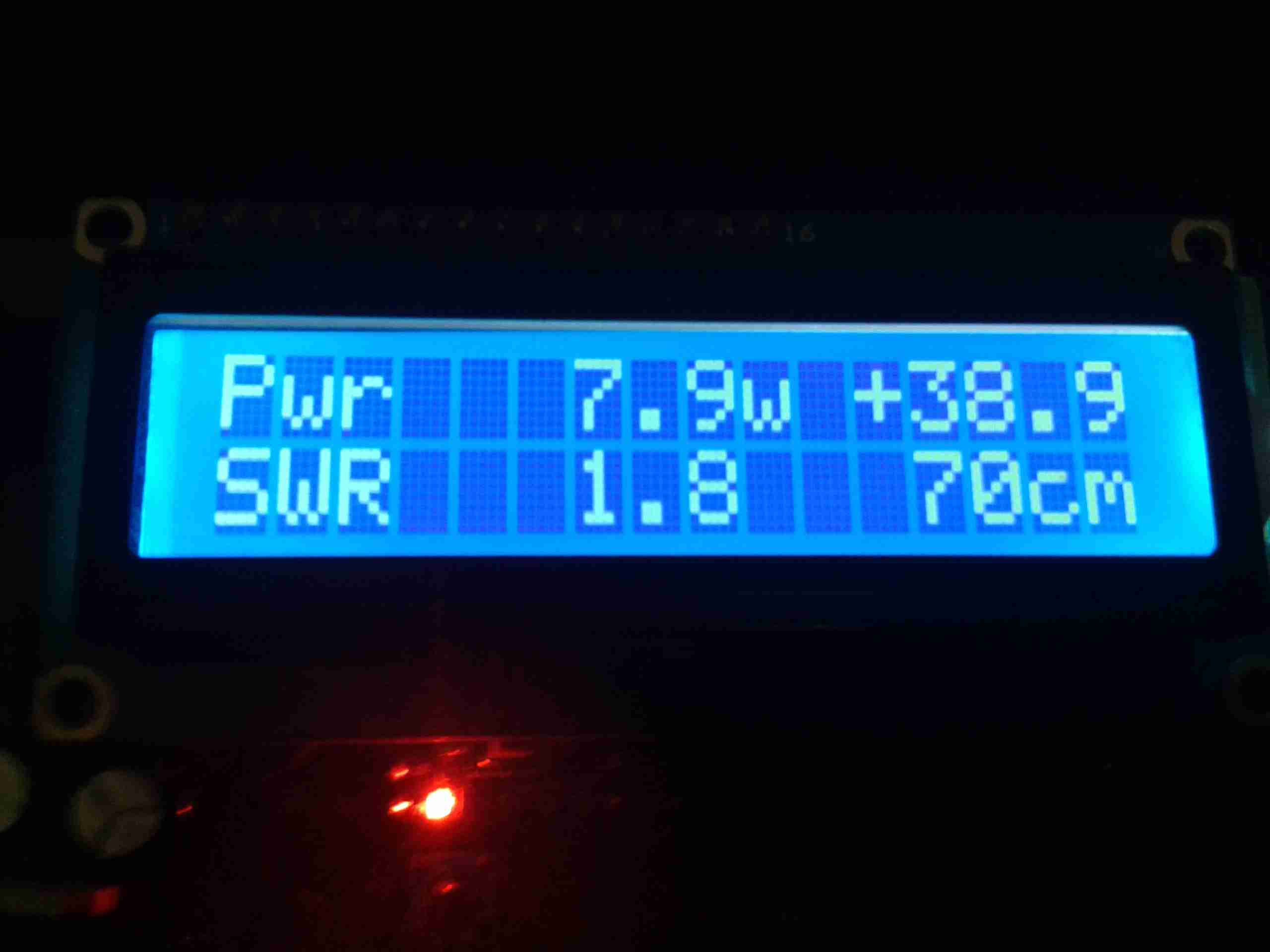
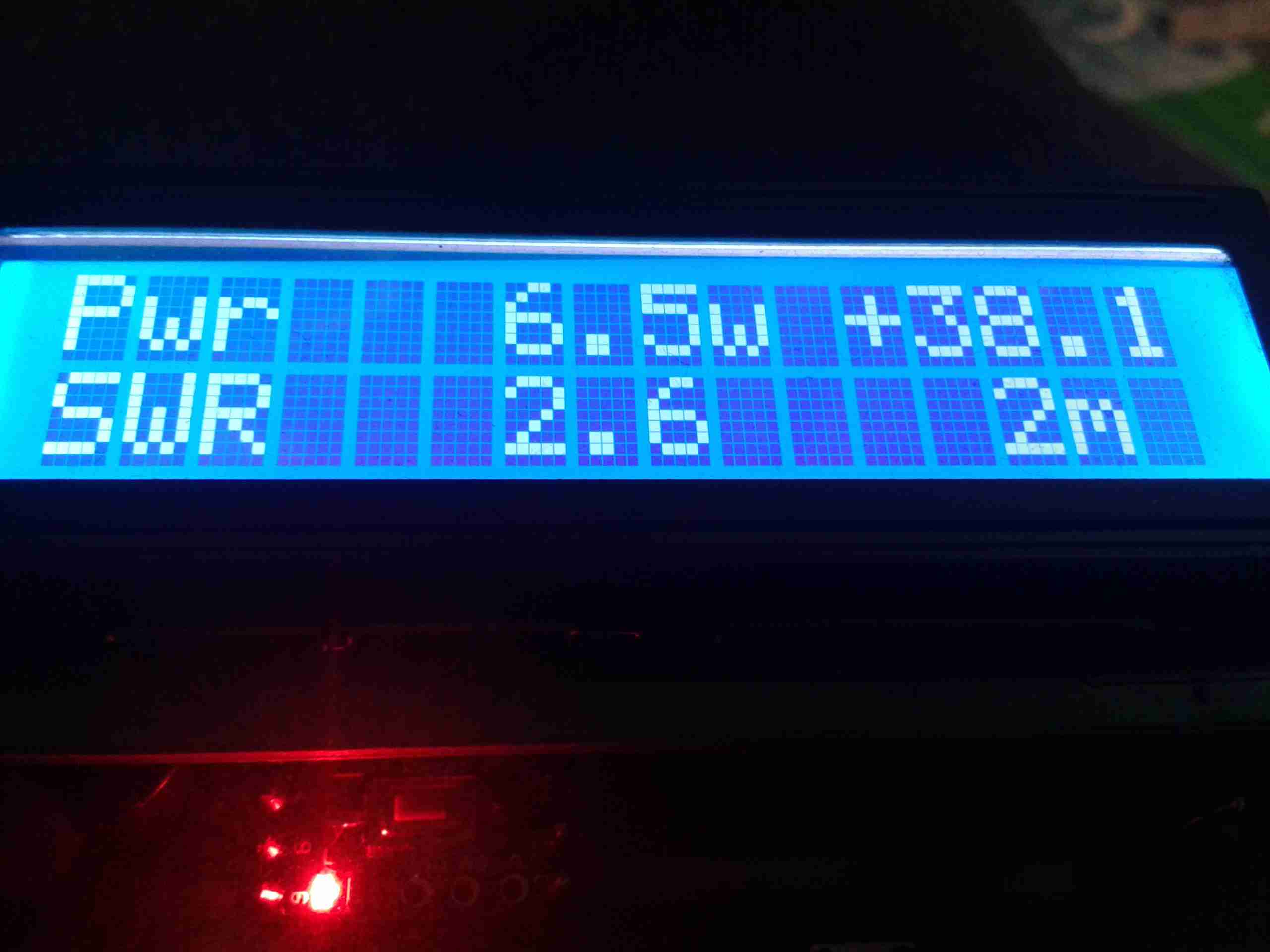
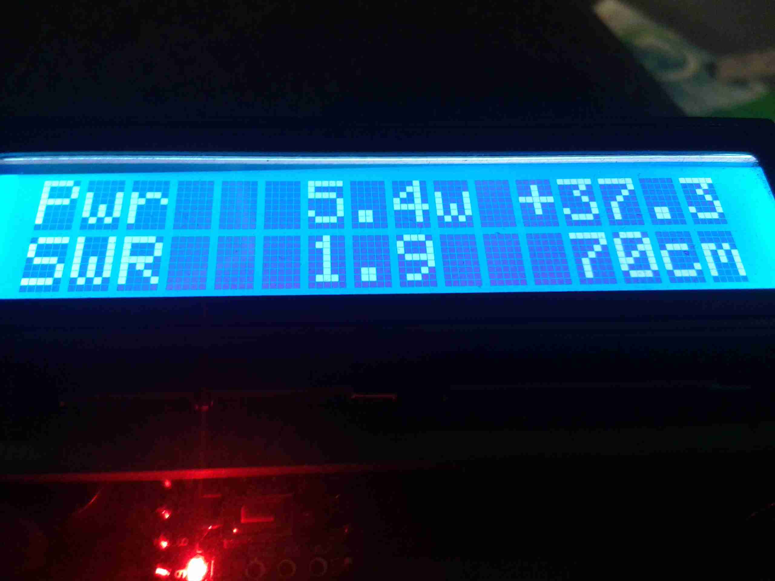
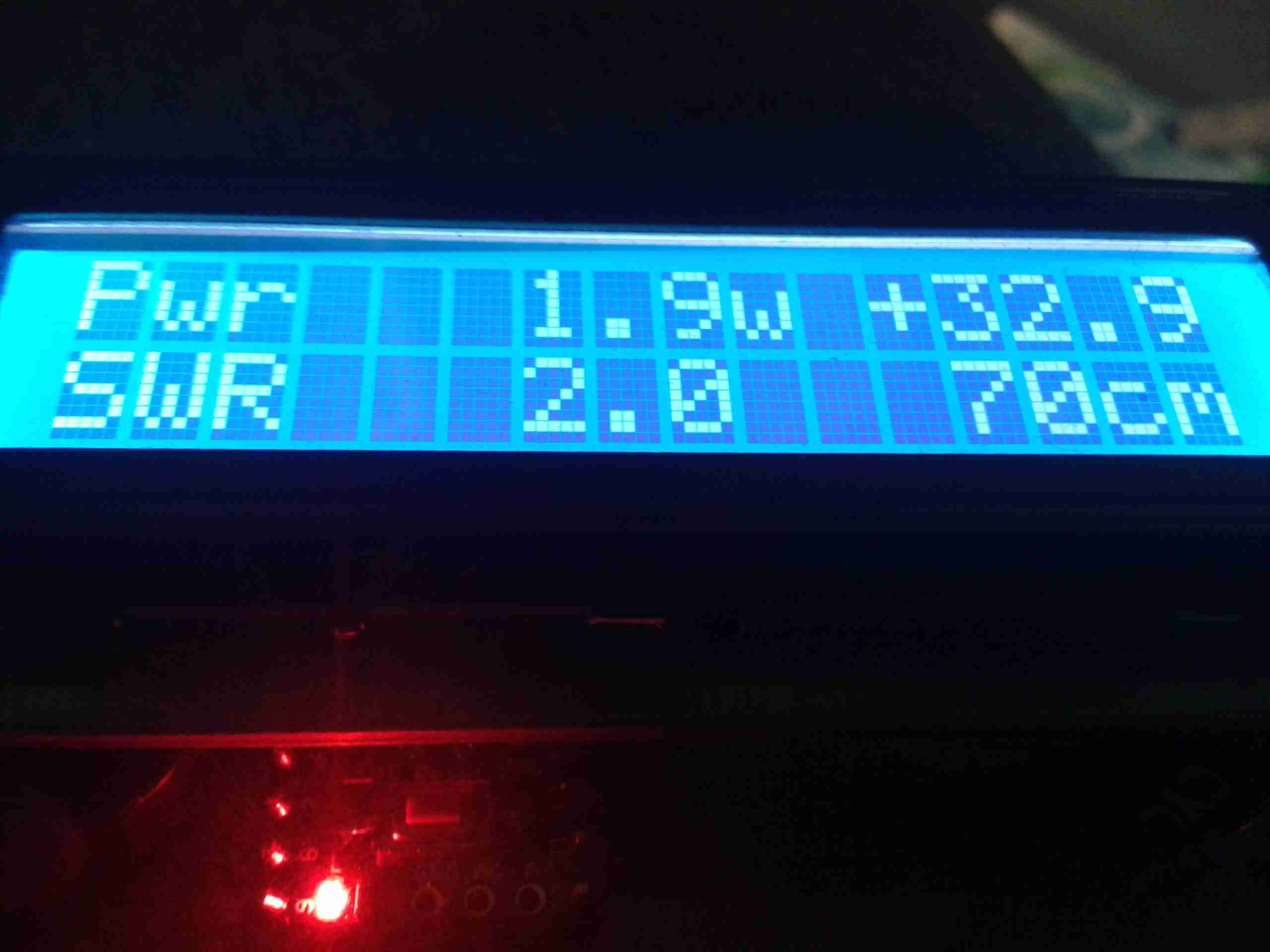
After calibration, here’s the readings on 2m & 70cm. These readings coincide nicely with the readings the GY561 produce, to within a couple tenths of a watt. SWR is more than 1:1 as the dummy load in the GY561 isn’t exactly 50Ω.
High Power VHFLow Power VHFHigh Power UHFLow Power UHF
Shortly I’ll calibrate against 6m & 10m so I can use it on every band I have access to 🙂
Onboard the boat we have a small issue with a weak TV signal, and this coupled with a 60′ long run of coax is an issue. Due to the loss in the coax, we’ve lost most of the already weak signal.
To try & solve this issue, I’m fitting a masthead amplifier unit.
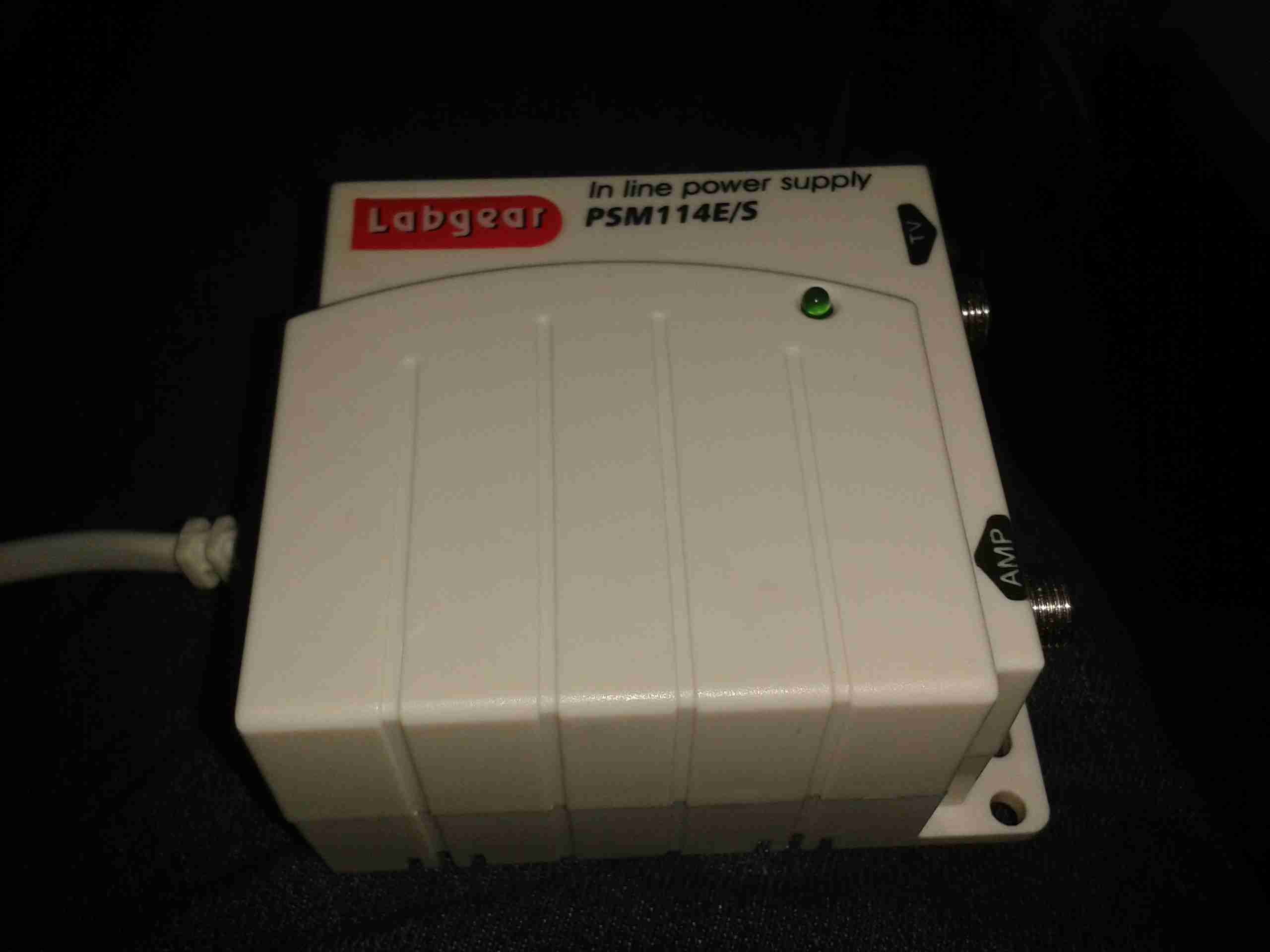
These amplifiers are fed power down the same coax that’s carrying the RF signal, and a special power supply is supplied with the amplifier for this. However it’s only 240v AC, no 12v version available.
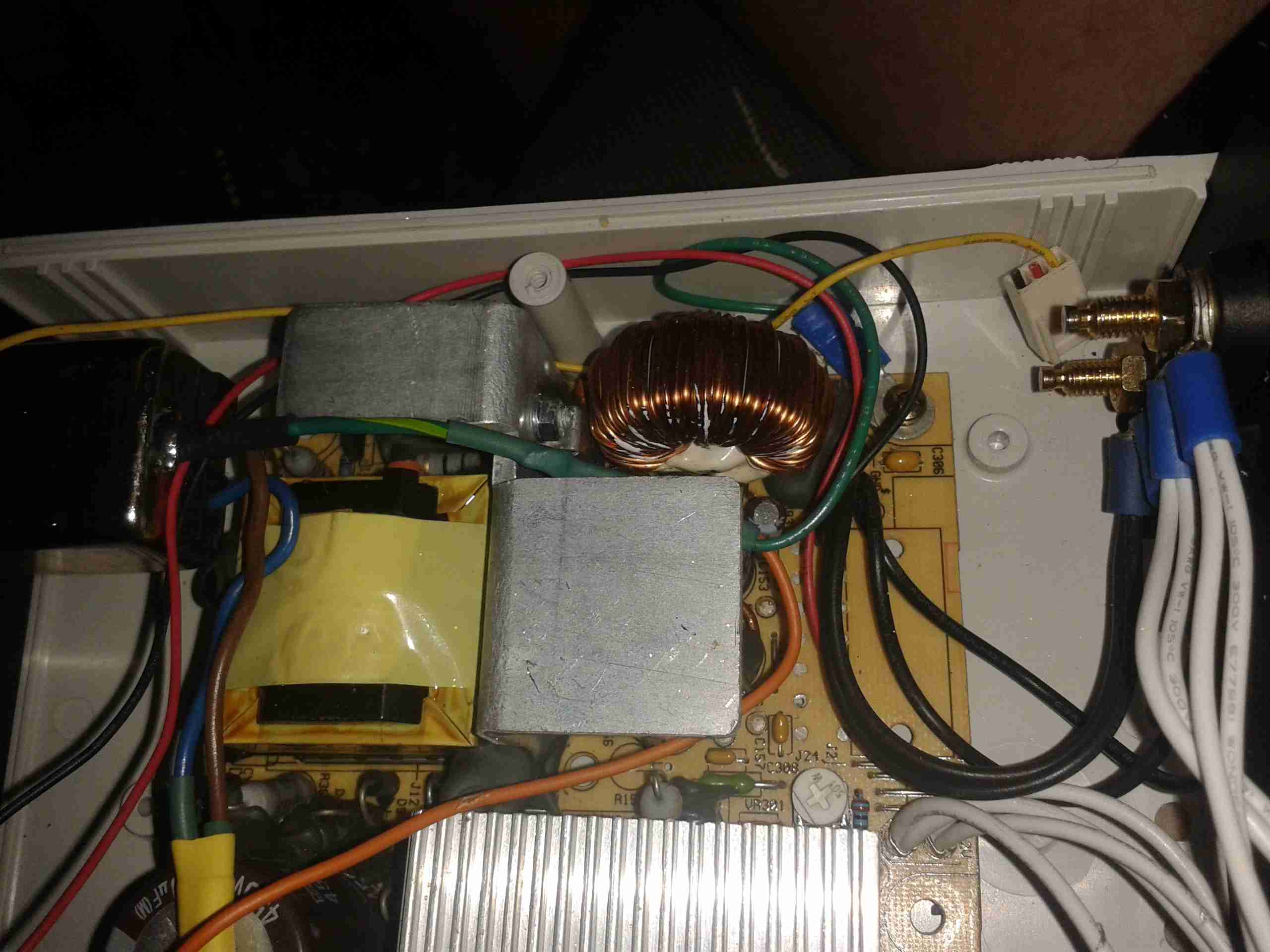
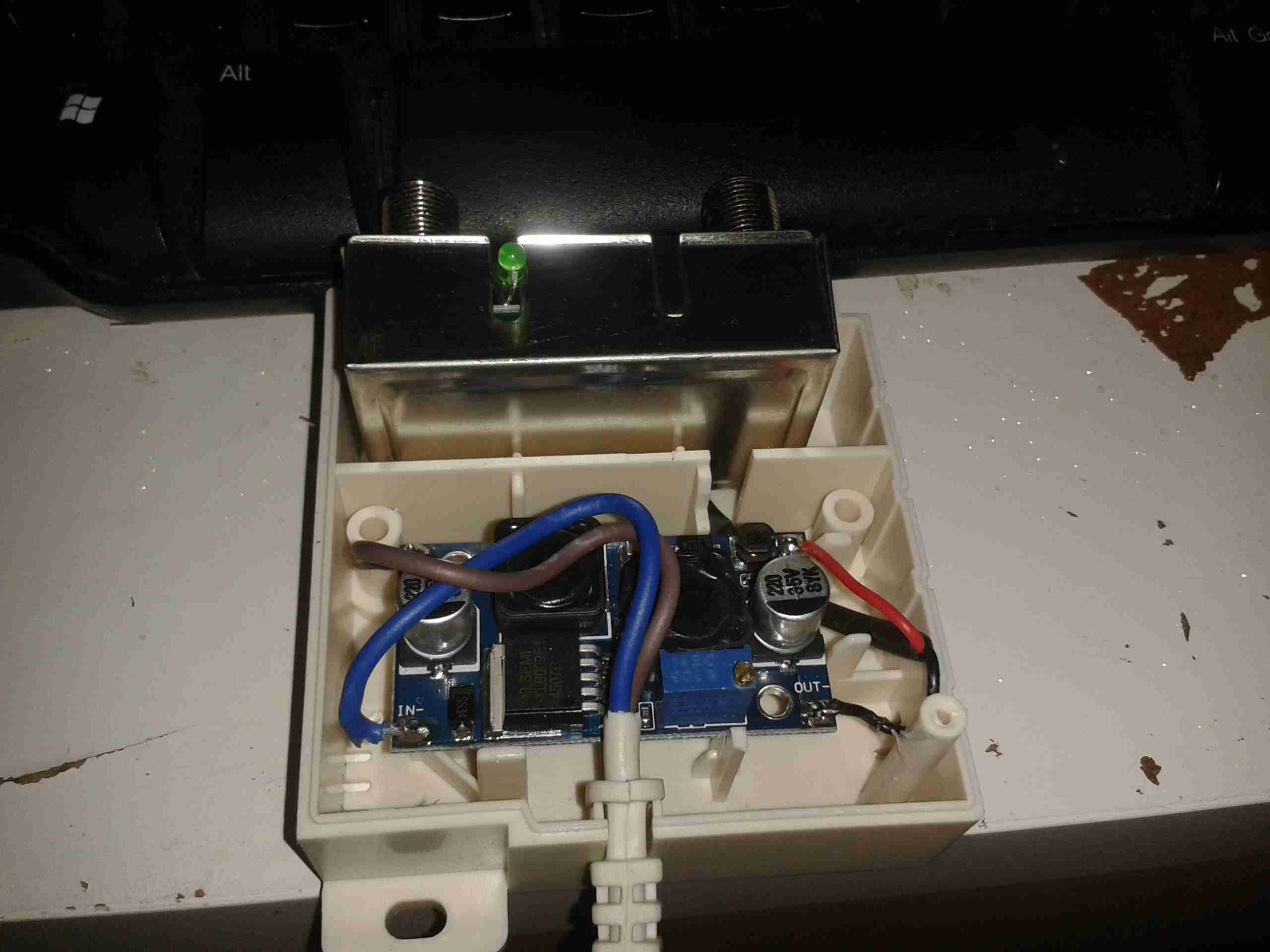
Here’s the power supply unit, which fits into the coax between the TV & the antenna.
Amplifier Supply
Luckily the 240v supply is easily removable & here has been replaced with a 12v regulator.
New Supply
There’s not very much inside the shielding can, just a few filter capacitors & an RF choke on the DC feed, to keep the RF out of the power supply system.
The original cable is used, so the supply doesn’t even look like it’s been modified from the outside.
More to come on this when I get the amplifier installed along with the new coax run 🙂
Since my new Wouxun has audio output jacks, I figured it would be useful to have the ability to record what my rig hears, if anything interesting comes on the air.
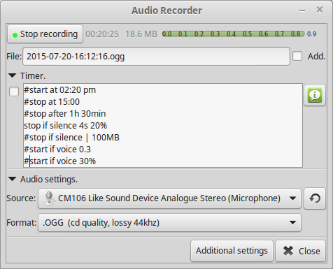
Under Linux, I use an application called, (creatively enough), Audio Recorder.
Recorder Screenshot
Using a simple connection to the mic input on a USB soundcard, I can capture everything the radio hears. Unfortunately this doesn’t work for outgoing audio, so it’s not much good at capture of my personal QSOs. For this I will have to set up another radio to act as the main receiver.
At some point in the future I will implement this with a Raspberry Pi as the audio capture server.
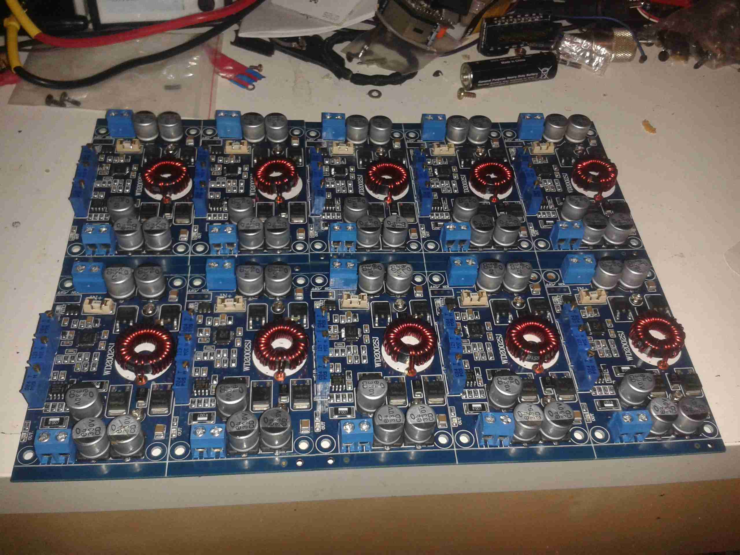
Here’s a sneak preview of my next upcoming project. The target is building a monster DC-DC converter, capable of 70A continuous output, 100A surge.
DC-DC Converter Modules
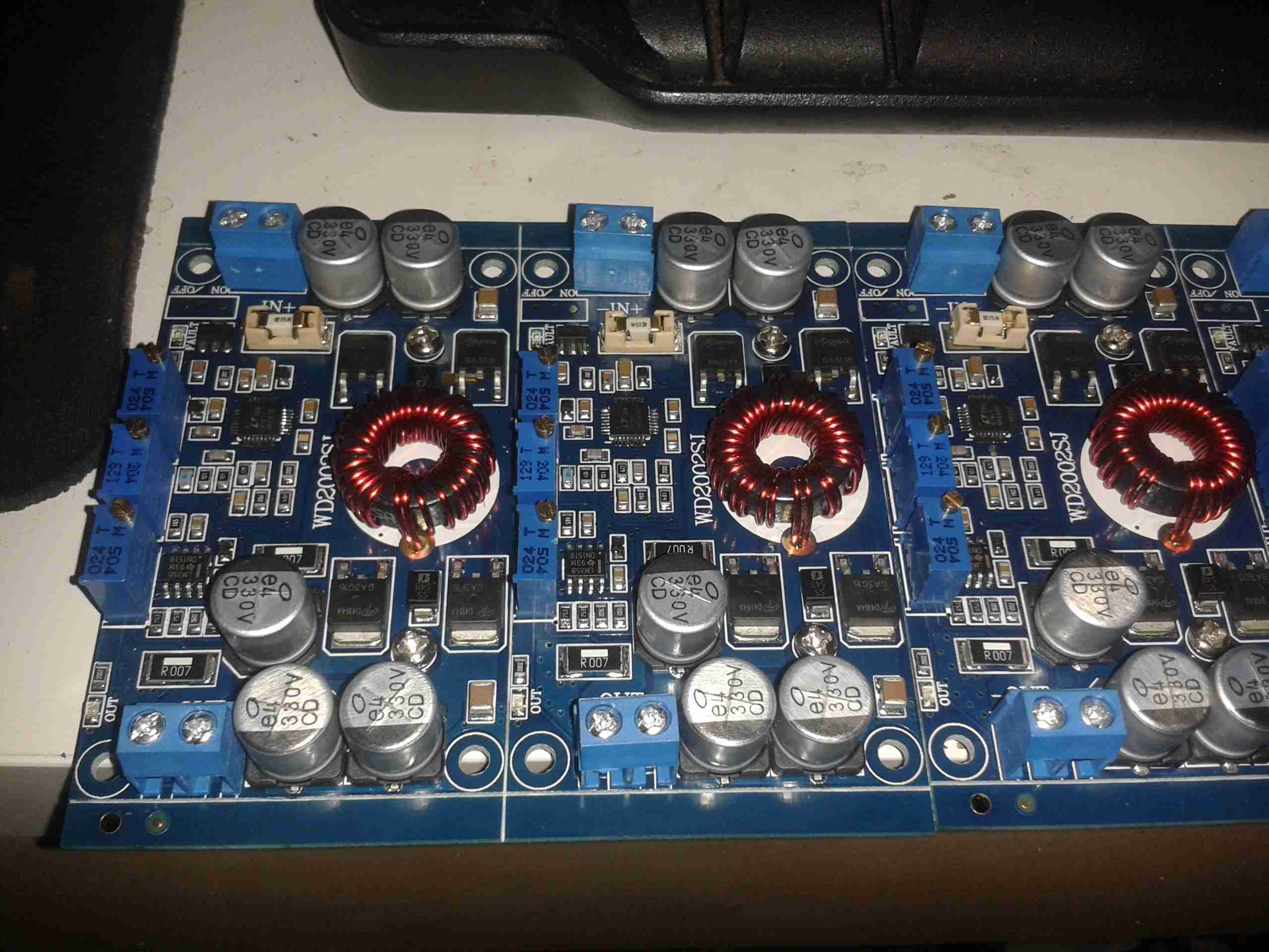
Here’s the 10 modules, each rated at up to 7A continuous & 10A surge. I ordered so many that they turned up still panelised!
Closeup
Tip Jar
If you’ve found my content useful, please consider leaving a donation by clicking the Tip Jar below!
All collected funds go towards new content & the costs of keeping the server online.