Posted on 2 Comments

EpEver MT50 Control Panel Teardown

MT50 Control Panel
MT50 Control Panel

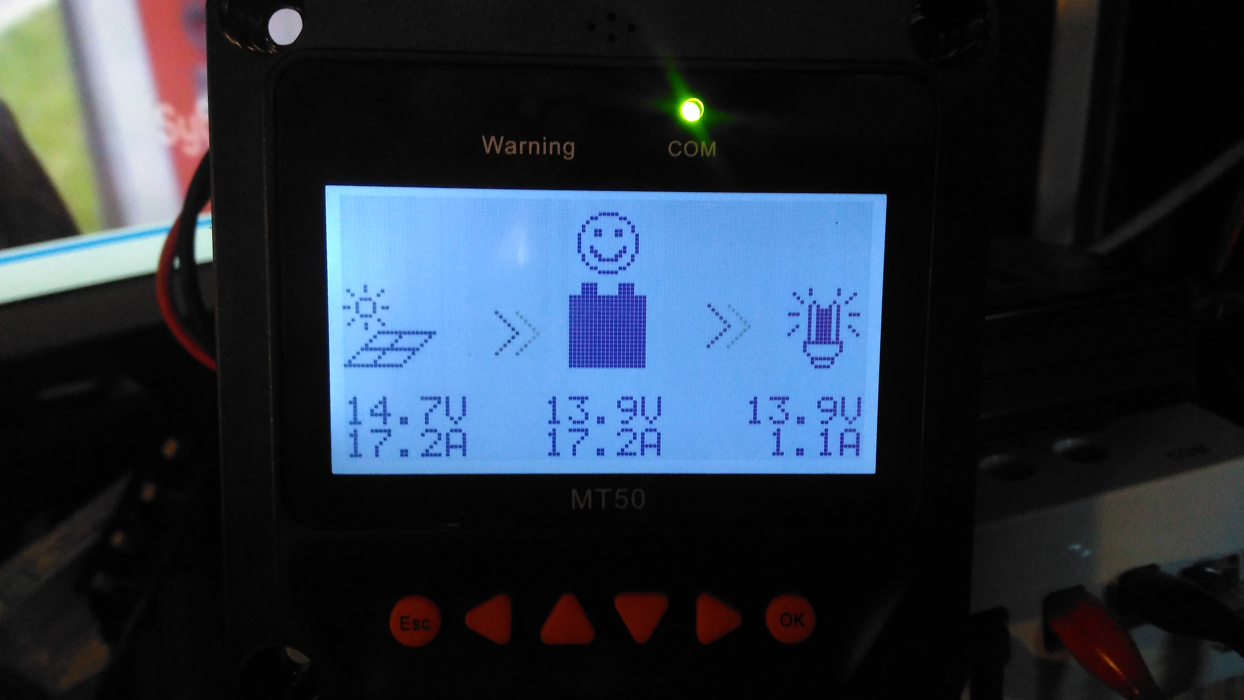
Here’s the MT50 controller from EpEver, that interfaces with it’s Tracer MPPT solar charge controllers, and gives access to more programming options on the charge controllers, without the need for a laptop. The display is a large dot-matrix unit, with built in backlight. Above is the display on the default page, showing power information for the entire system.

PCB Rear
PCB Rear

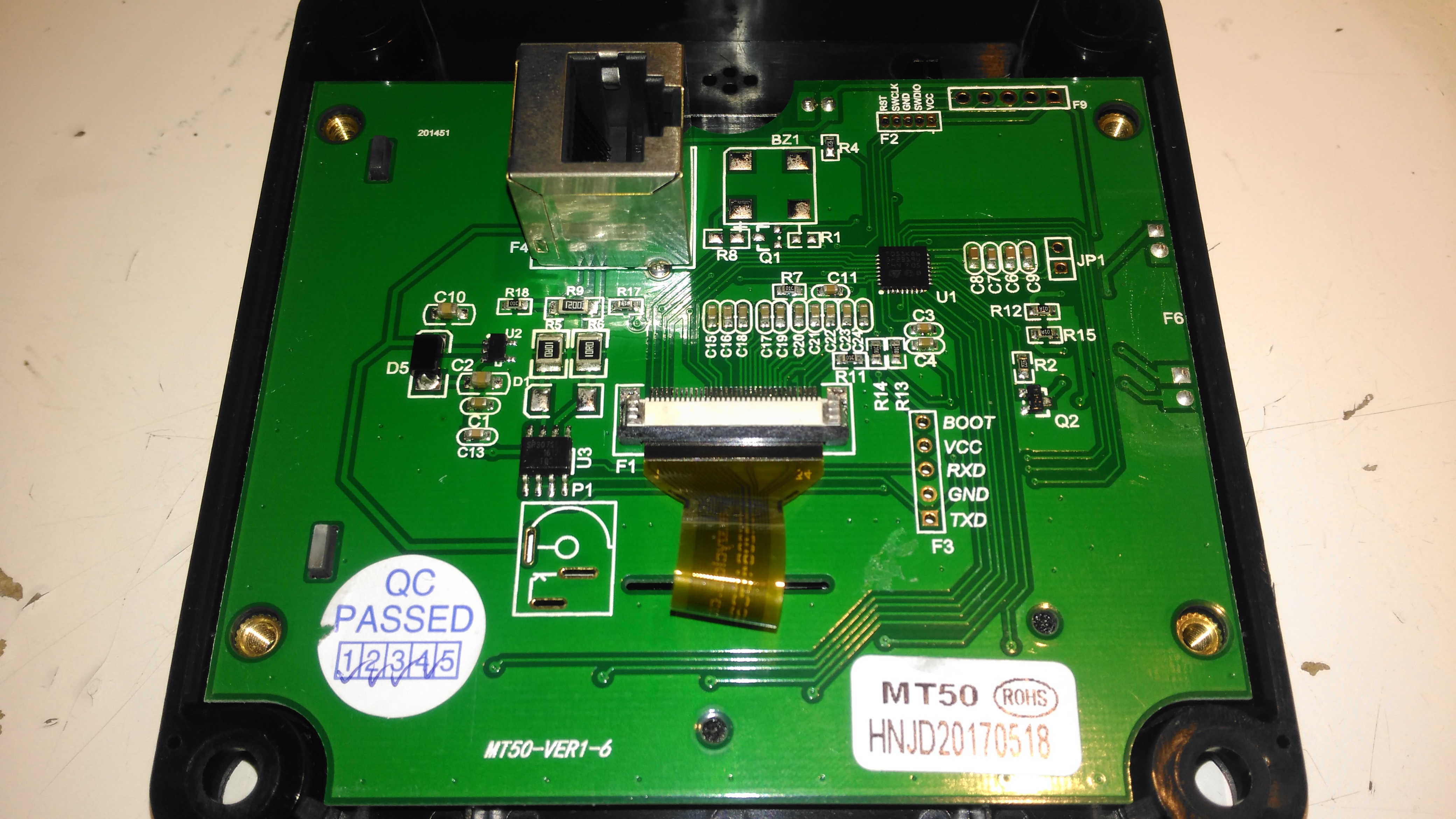
The rear plastic cover is held in place by 4 machine screws, which thread into brass inserts in the plastic frame – nice high quality touch on the design here, no cheap self tapping plastic screws. Both power & data arrive via an Ethernet cable, but the communication here is RS-485, and not compatible with Ethernet! The PCB is pretty sparse, with comms & power on the left, LCD connection in the centre, and the microcontroller on the right.

RS-485 Transceiver
RS-485 Transceiver

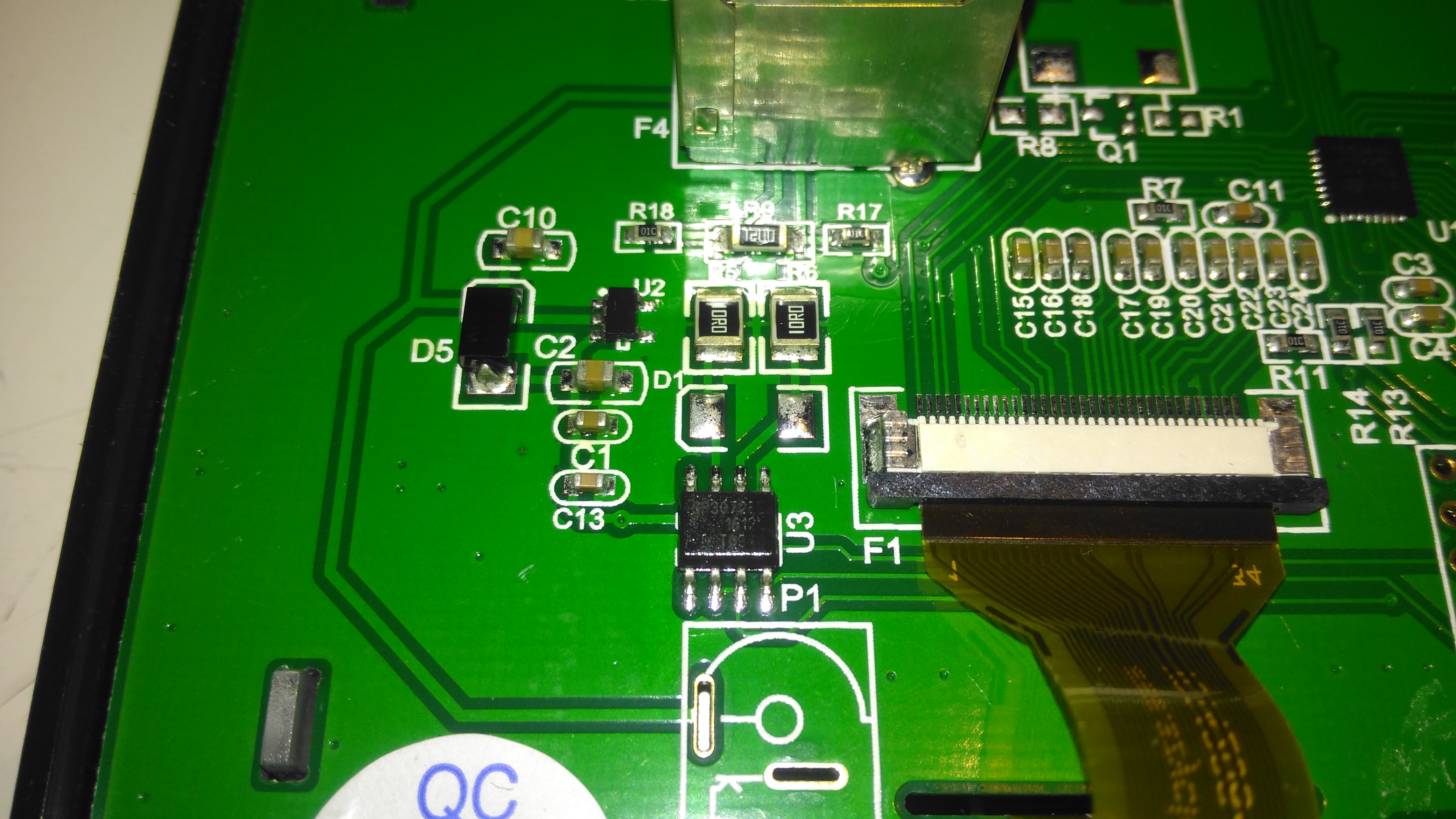
On the left of the board is the RS0485 transceiver, and a small voltage regulator. There’s also a spot for a DC barrel jack, which isn’t included in this model for local power supply.

STM32 Microcontroller

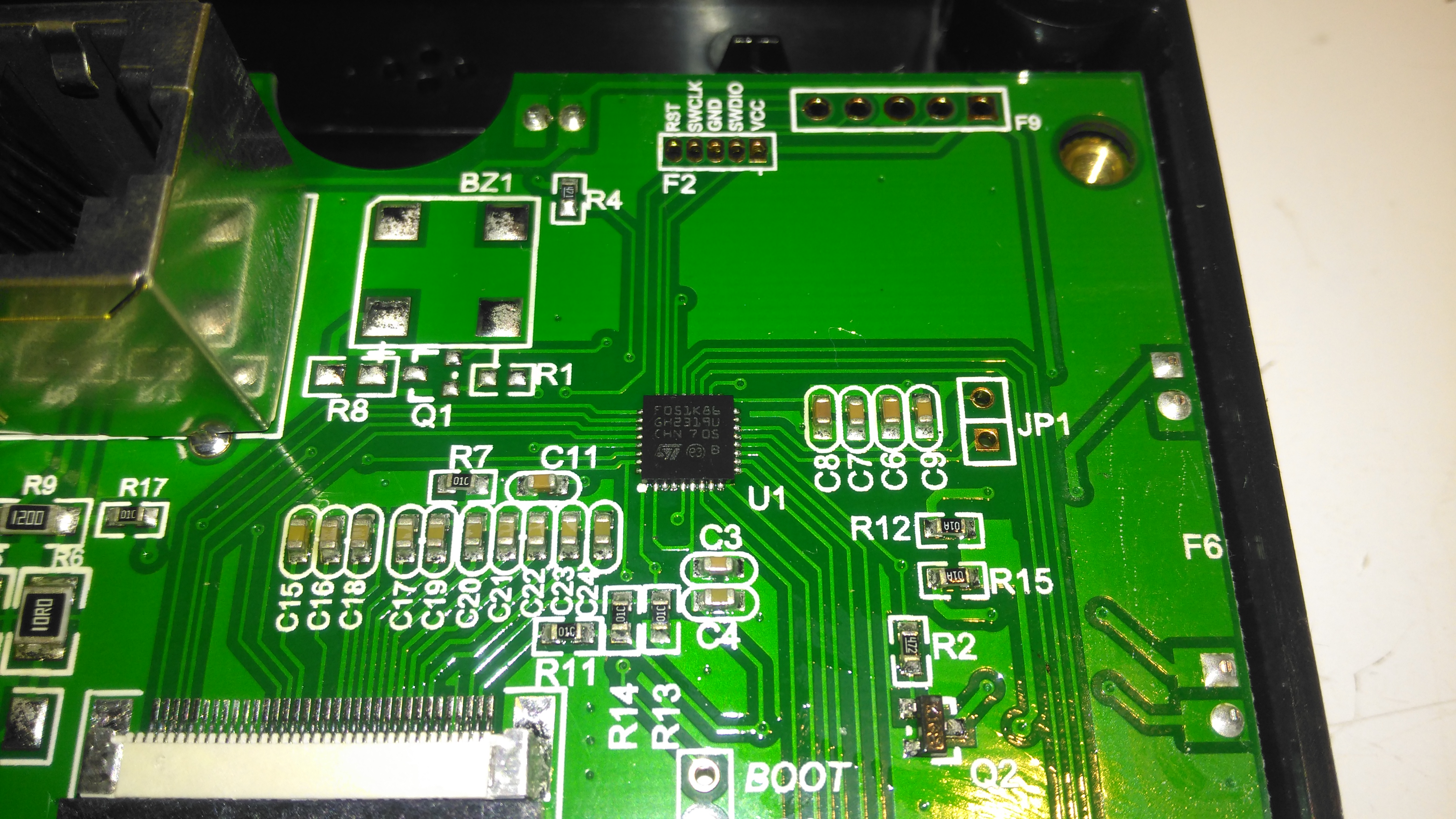
The other side of the board holds the main microcontroller which communicates with the charge controller. This is a STM32F051K8 from ST Microelectronics. With a 48MHz ARM Cortex M0 core, and up to 64K of flash, this is a pretty powerful MCU that has very little to do in this application.

PCB Front
PCB Front

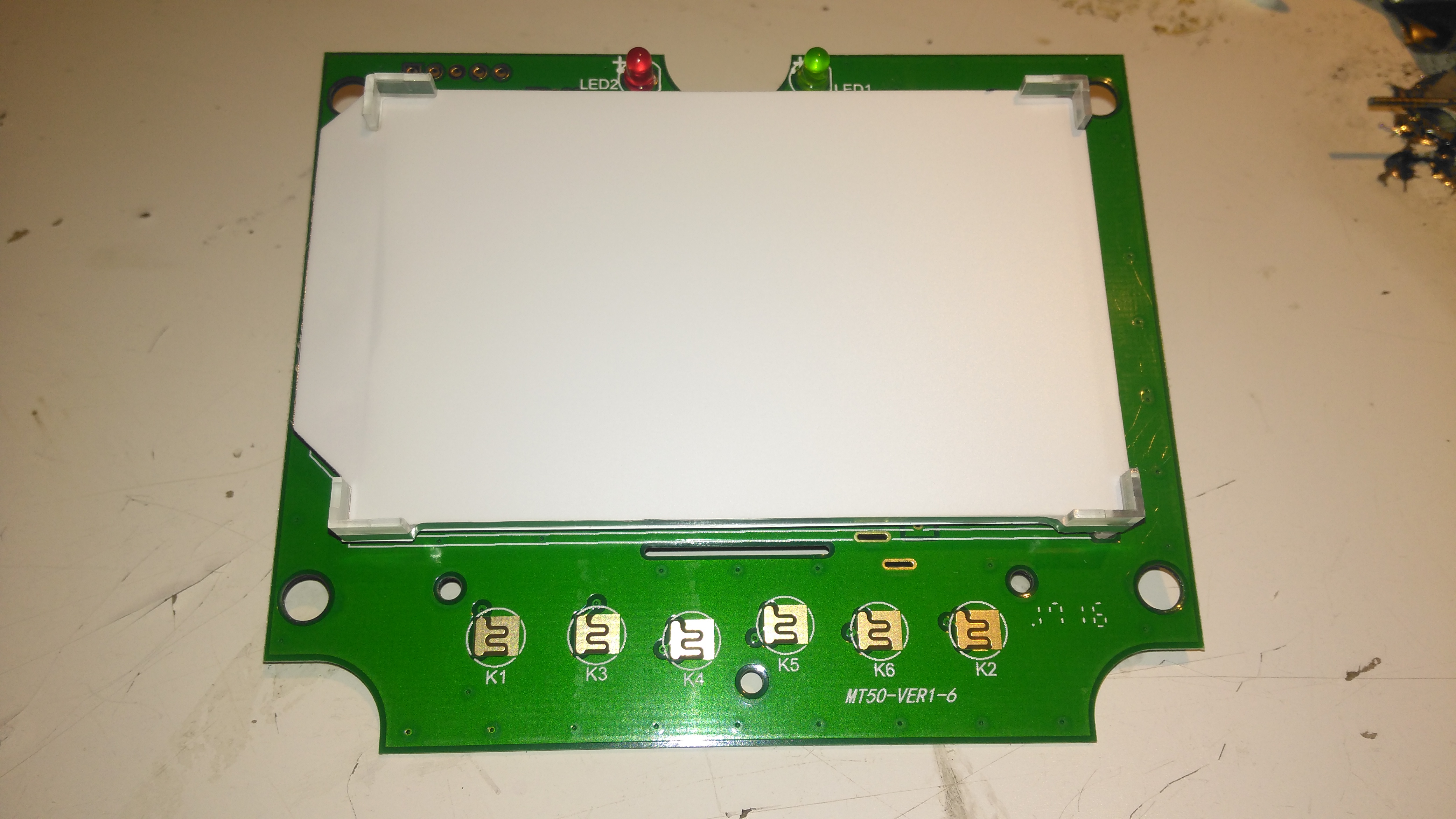
The front of the PCB has the ENIG contacts of the front panel buttons, and the LCD backlight assembly. There’s nothing else under the plastic backlight spreader either.

LCD Rear
LCD Rear

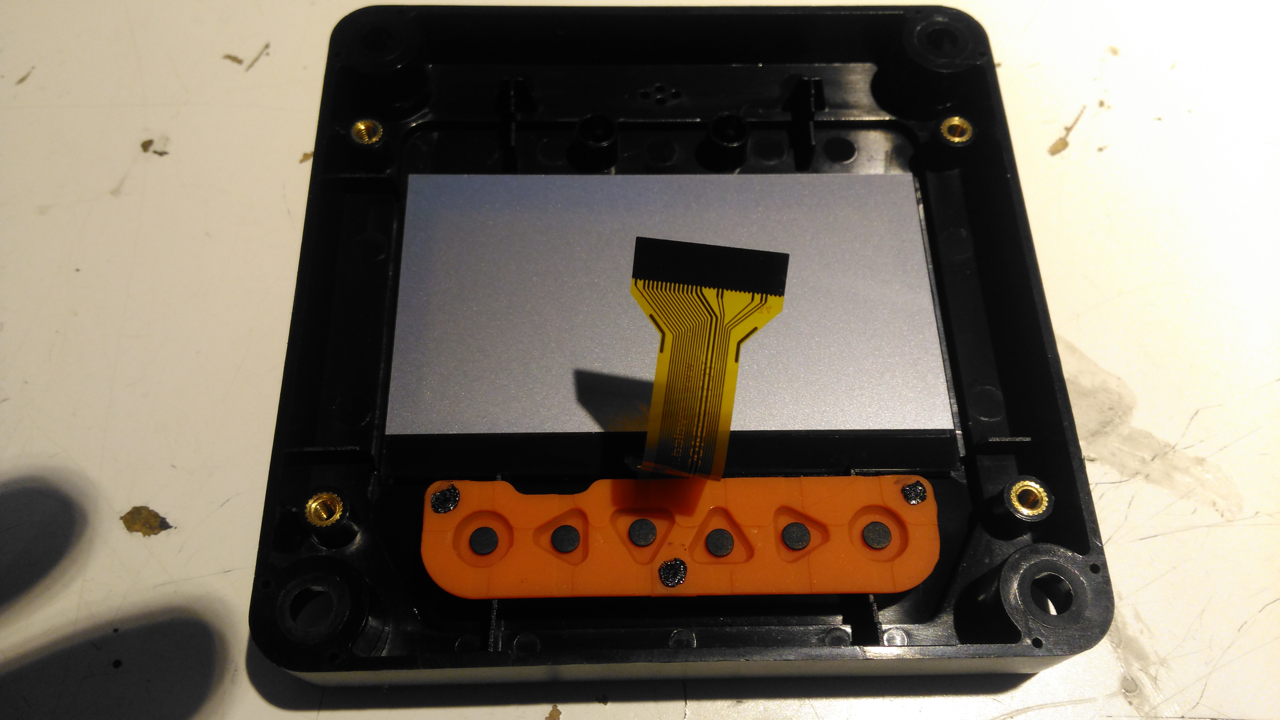
The front case holds the LCD module in place with glue, and the rubber buttons are placed underneath, which is heat staked in place.

LCD Model
LCD Model

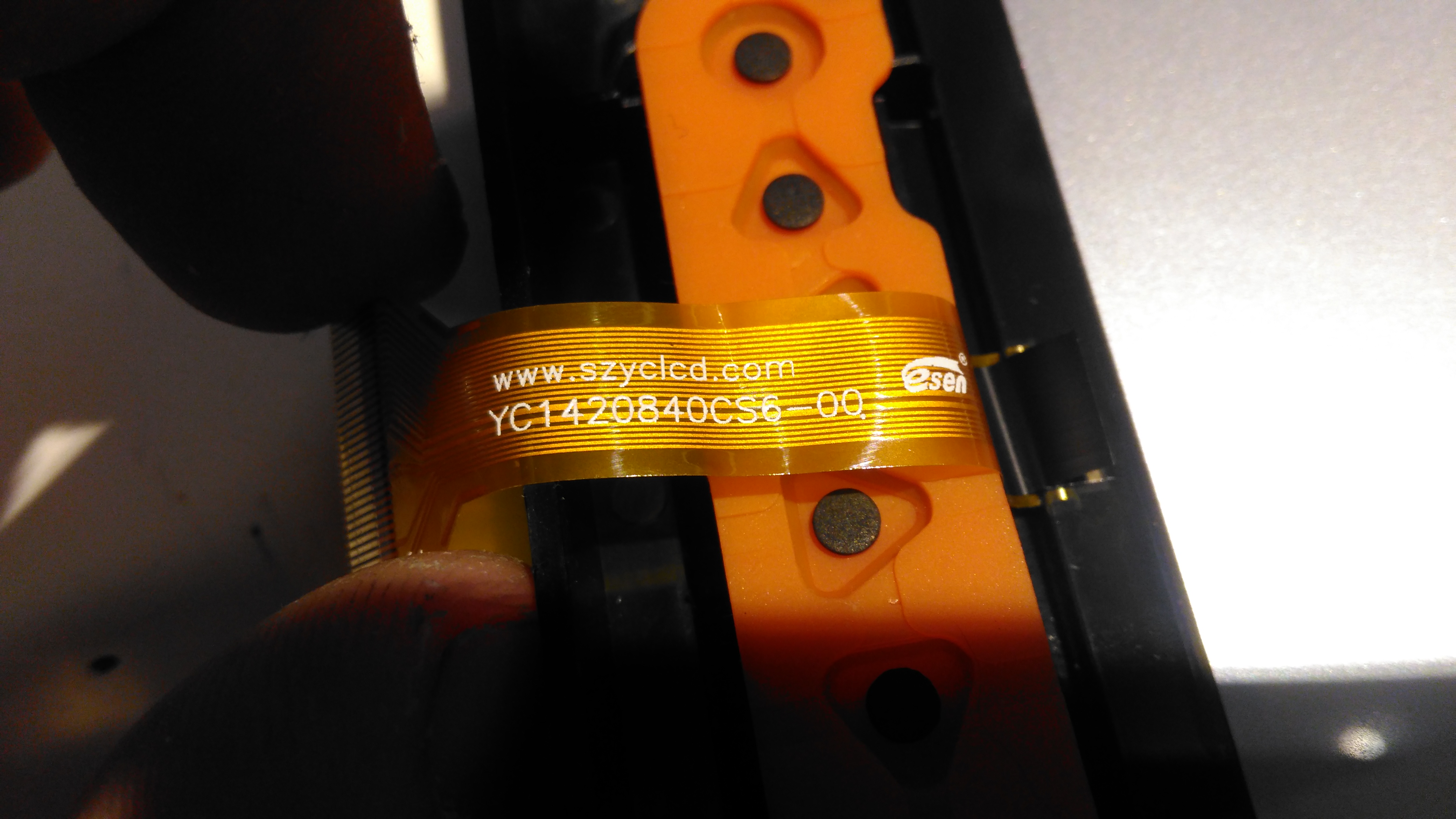
The LCD is a YC1420840CS6 from eCen in China. Couldn’t find much out about this specific LCD.

Posted on Leave a comment

LG Flatron 22EA53VQ-P Power Issue

I was recently given a pretty nice LED backlit 1080p LG monitor, with the instruction that it wouldn’t power on correctly. The monitor would power on as far as the standby light, but when fully powered on, would flash the backlight momentarily then shut down. A power supply issue was immediately suspected.

LCD Logic Board
LCD Logic Board

I popped the covers off the monitor itself first, thinking that it was an electrolytic gone bad in the backlight DC-DC converter. Not to mention the fact that cracking into a wall-wart type of PSU is only occasionally possible without the use of anger & large hammers. (Cracking the glue with the handle of a screwdriver doesn’t work so well when the factory went a bit nuts with the glue/ultrasonic welder). As can be seen in the photo, there’s not much inside these monitors, the logic is a single-chip solution, the rest of the PCB is dedicated to supplying the power rails for the various circuits. On the left is the power input & the DC-DC converter for the backlight, along with the DC-DC converter supplying the logic circuits. None of the capacitors here are damaged, everything looks good.
I then measured the output of the PSU, which under no load was the correct 19v DC. However applying any load caused the output voltage to drop like a proverbial brick. Applying a full load of 1.3A saw the output voltage drop so severely that the PSU tripped on it’s UVLO.

200mA Load
200mA Load

At 200mA of load the factory PSU is already dropping to 18v, with a 5.3kHz switching frequency appearing.

500mA Load
500mA Load

At higher load the frequency increases to 11.5kHz & the output voltage has dropped to 11.86v!

750mA Load
750mA Load

750mA was as high as I could make the supply go without it tripping itself out – the UVLO circuit trips at 9v. 12.6kHz is now riding on the severely low DC at this point.

PSU Ratings
PSU Ratings

The power supply is supposed to be rated at 1.3A at 19v, however with this fault it’s getting nowhere near that. The LG brand is on this PSU but it’s contracted out to Shenzen Honor Electric Co. Ltd.

Output Electrolytic
Output Electrolytic

Here’s the problem with this PSU. The output electrolytic has ballooned. I don’t have an ESR tester, but this cap has gone way past it’s sell-by date. It’s position right next to the heatsink with the output rectifier diodes has probably cooked it. The PSU isn’t that badly built for a Chinese one – there’s plenty of creepage distance on the PCB & even a couple of isolation slots.

Posted on Leave a comment

ViewSonic VA2232W-LED Monitor 12v Conversion

ID Label
ID Label

On the quest to get things on board replaced that are heavy users of power, the monitor in the main cabin was next. The original CCFL-backlit monitor was very heavy on 12v power, at 5A. This meant falling asleep watching TV would result in severely flattened batteries.

Replacement with a suitable LED-backlit monitor was definitely required. The cheapest on eBay was a ViewSonic VA2232W-LED, so I took to work converting it from 240v to 12v operation.

Back Cover Removed
Back Cover Removed

There are no screws holding these monitors together, so a spudger & frequent swearing got the back off. The shield holding the circuitry is also not screwed down, only attached to the back of the LCD panel with aluminium shielding tape.

Power PCB Trackside
Power PCB Trackside

Once the tape has been cut, the main power board is accessible. The large IC on the left is the main backlight LED driver.

In this case the monitor requires a pair of rails from the supply, 18.5v for the backlight circuitry & 5v for the logic.

DC-DC Regulators
DC-DC Regulators

A pair of DC-DC converters has been fitted in the small space between the power & control boards.

PCB Connection Points

To save me some work & keep maximum compatibility, I’ve not modified the existing supply, just attached the new DC-DC converter outputs onto the corresponding outputs of the factory PSU. The 12v input leads are routed out of the same gap as the mains IEC connector, with some hot glue over the mains input solder points to provide some more insulation.

Wiring Tidied
Wiring Tidied

The wiring is tidied up with hot glue so the back cover will go back on.

Total current draw at 12v is 1.4A.

Posted on 1 Comment

Dell E207WFPc Monitor 12v Conversion

I’m still on my crusade of removing every trace of 240v mains power from my shack, so next up are my computer monitors.

I have 4 Dell monitors, of various models, hooked up to my main PC.

The monitor here is a Dell E207WFPc 20″ widescreen model. There will be more when I manage to get the others apart to do the conversion. However I’m hoping that the PSU boards are mostly the same.

Panel Removed
Panel Removed

There are no screws holding these monitors together, the front bezel is simply clicked into place in the back casing, these clips are the only thing that holds the relatively heavy glass LCD panel & it’s supporting frame! The image above shows the panel removed. The large board on the left is the power supply & backlight inverter, the smaller one on the right is the interface board to convert the DVI or VGA to LVDS for the LCD panel itself.

PSU Board
PSU Board

Here’s a closeup of the PSU board, the connector at centre right at the top of the PCB is the main power output, and also has a couple of signals to control the backlight inverter section of the PSU, on the left side. The PSU requirements for this monitor are relatively simple, at 14.5v for the backlight & 5v for the logic board.

PSU
PSU

Here’s the top of the PSU board, very simple with the mains supply on the right side, and the backlight inverter transformers on the left.

Hooked In
Hooked In

Here I’ve hooked into the power rails on the supply, to attach my own 12v regulators. The green wire is +14.5v, and the purple is +5v. Black is common ground.

5v Regulator
5v Regulator

On doing some testing, the backlight inverter section doesn’t seem to mind voltages between 11.5-14.5v, so a separate regulator isn’t required there. Even running off batteries that’s within the range of both charging & discharging. The only regulator required is a 5v one to reduce the input voltage for the logic PCB.

First Test
First Test

On applying some 12v power to the regulator input, we have light! Current draw at 12.5v is 2.65A for a power consumption of 33W.

12v Input
12v Input

There’s plenty of room in the back casing to mount a 12v input socket, I have left the mains supply intact so it can be used on dual supply.

Final Wiring
Final Wiring

Here’s the 5v regulator mounted on the back of the casing, all wired up & ready to go.

Posted on Leave a comment

Garmin eTrex

Front
Front

Pocket sized GPS navigator. Here is shown the greyscale dot matrix LCD.

Interface
Interface

Serial interface on the back of the unit. Pinout from left is +3v, Rx, Tx, GND.

PCB Back
PCB Back

PCB Removed from the casing. RTC backup battery in the centre of board, CPU & flash ROM on the left. GPS chipset is under the shield on the right.

PCB Front
PCB Front

Front of the PCB, GPS antenna on the right, LCD panel left.

LCD Removed
LCD Removed

LCD folded back from the PCB. Driver IC can be seen attached to the ribbon.

Electroluminescent Panel

LCD Panel backlight. Requires 200v AC at 20kHz to glow green.

GPS Reciever
GPS Reciever

GPS chipset with the shield removed.