A while back I found myself in the need of an adjustable RF attenuator capable of high-GHz operation. As luck would have it I had an old Spectrum analyser on the shelf at work, which we had retired quite some time ago.
Spectrum analysers being quite capable test instruments, I knew that the input attenuation would be done with a standalone module that we could recover for reuse without too much trouble.
The attenuator module
Here’s the module itself, with the factory drive PCB removed from the bottom, showing the solenoids that operate the RF switches. There are test wires attached to them here to work out which solenoid switches which attenuation stage. In the case of this module, there are switches for the following:
Input select switch
AC/DC coupling
-5dB
-10dB
-20dB
-40dB
For me this means I have up to -75dB attenuation in 5dB steps, with optional switchable A-B input & either AC or DC coupling.
Drive is easy, requiring a pulse on the solenoid coil to switch over, the polarity depending on which way the switch is going.
Building a Control Board
Now I’ve identified that the module was reusable, it was time to spin up a board to integrate all the features we needed:
Onboard battery power
Pushbutton operation
Indication of current attenuation level
The partially populated board is shown at right, with an Arduino microcontroller for main control, 18650 battery socket on the right, and control buttons in the centre. The OLED display module for showing the current attenuation level & battery voltage level is missing at the moment, but it’s clear where this goes.
As there weren’t enough GPIO pins for everything on the Arduino, a Microchip MC23017 16-Bit I/O expander, which is controlled via an I²C bus. This is convenient since I’m already using I²C for the onboard display.
Driving the Solenoids
A closer view of the board shows the trip of dual H-Bridge drivers on the board, which will soon be hidden underneath the attenuator block. These are LB1836M parts from ON Semiconductor. Each chip drives a pair of solenoids.
Power Supplies
The bottom of the board has all the power control circuitry, which are modularised for ease of production. There’s a Lithium charge & protection module for the 18650 onboard cell, along with a boost converter to give the ~9v rail required to operate the attenuator solenoids. While they would switch at 5v, the results were not reliable.
Finishing off
A bit more time later, some suitable firmware has been written for the Arduino, and the attenuator block is fitted onto the PCB. The onboard OLED nicely shows the current attenuation level, battery level & which input is selected.
There’s a common problem with all Software Defined Radios – their input stage is wide open, and therefore susceptible to desensitisation by local high power transmitters. The main culprits are broadcasts in the FM band, from 88-108MHz. Commercial stopband filters are available to solve this issue, by cutting out the FM Broadcast band. Before I ordered a commercially produced filter, I figured I’d try my hand at building my own.
DIY Stopband Filter
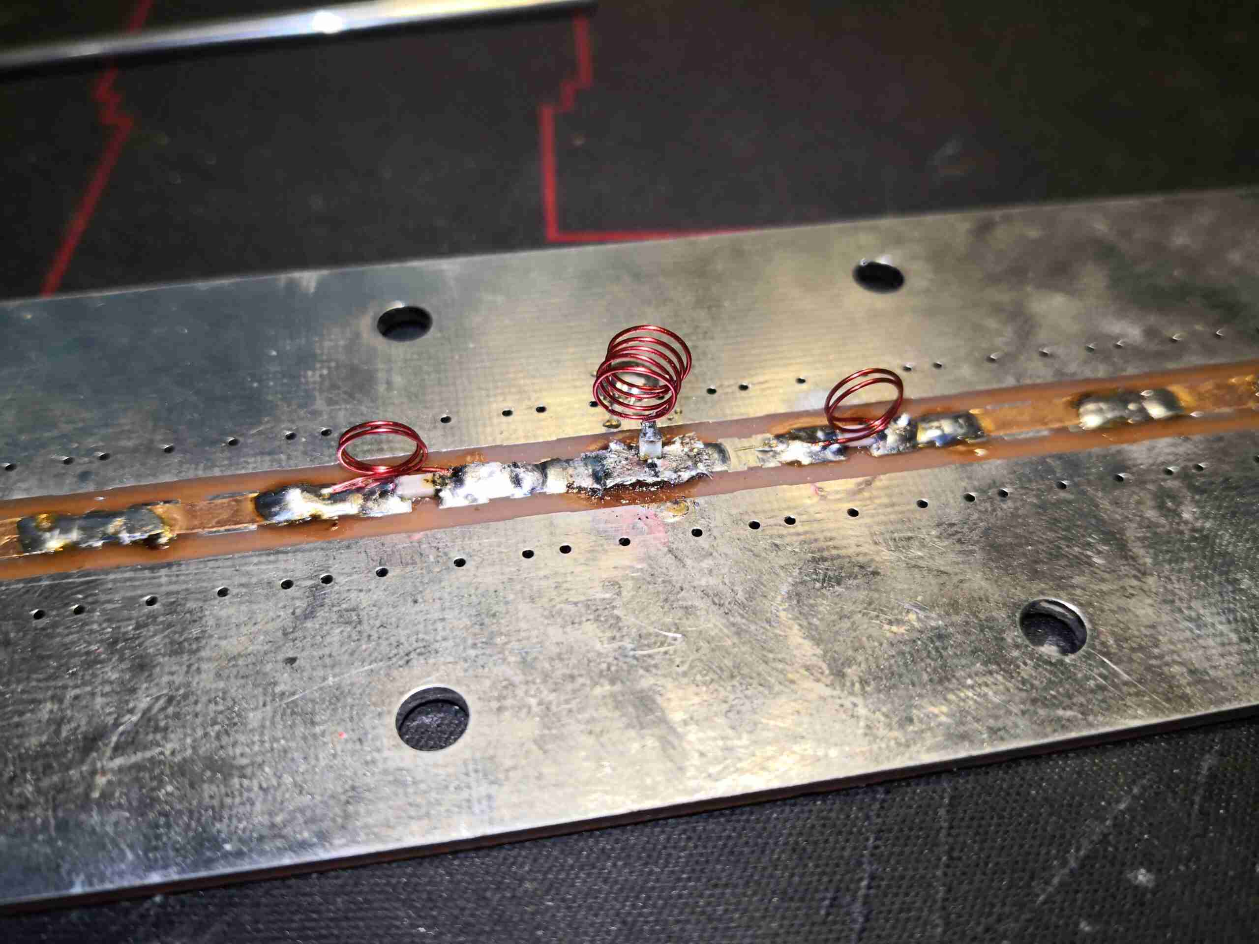
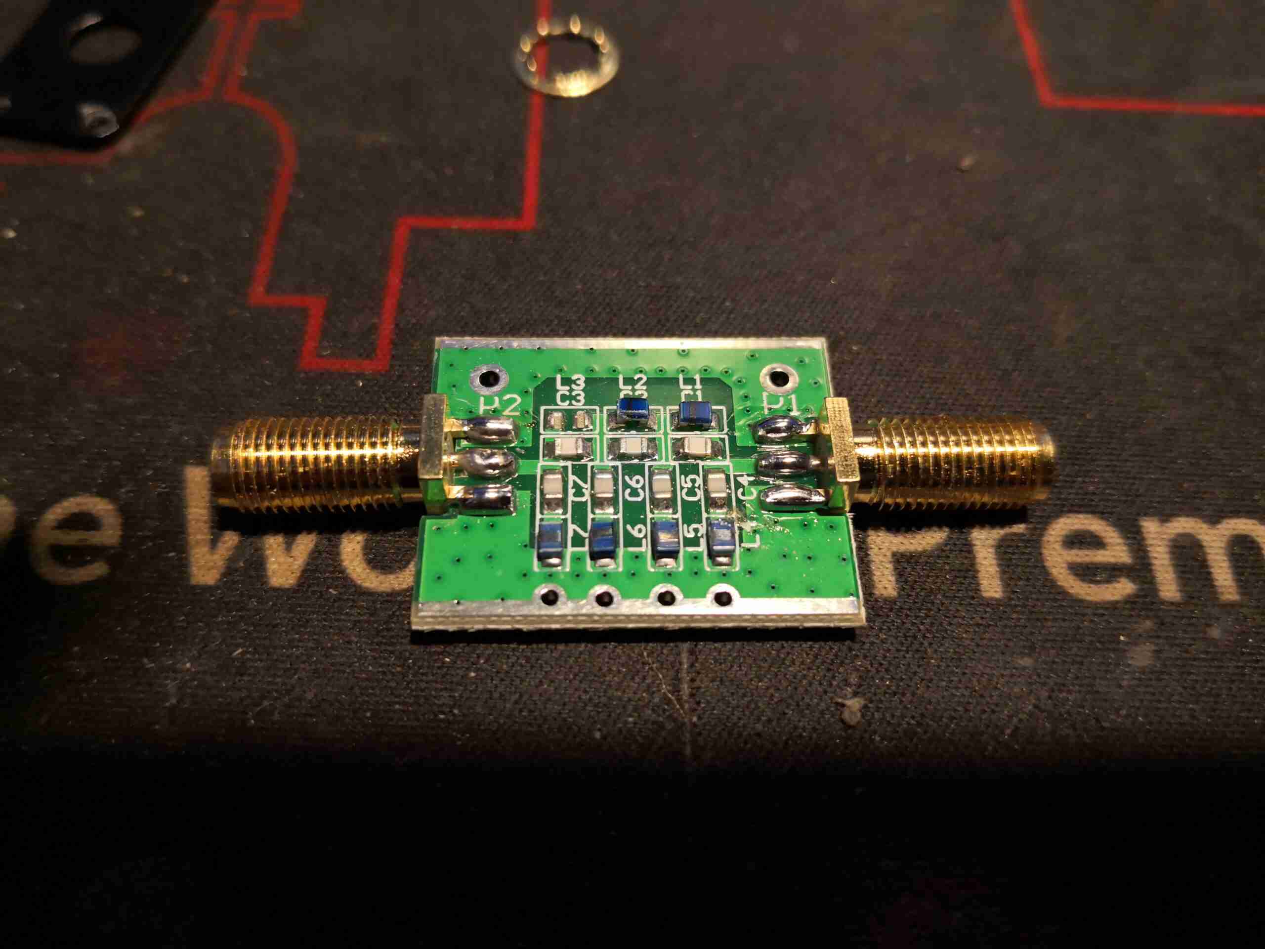
Here’s the filter I came up with, a Type 2 Chebyshev. It’s built on a prototype stripline PCB, with SMA connectors at either end for I/O. This was created with the help of a filter calculator, the response of the filter can be seen below:
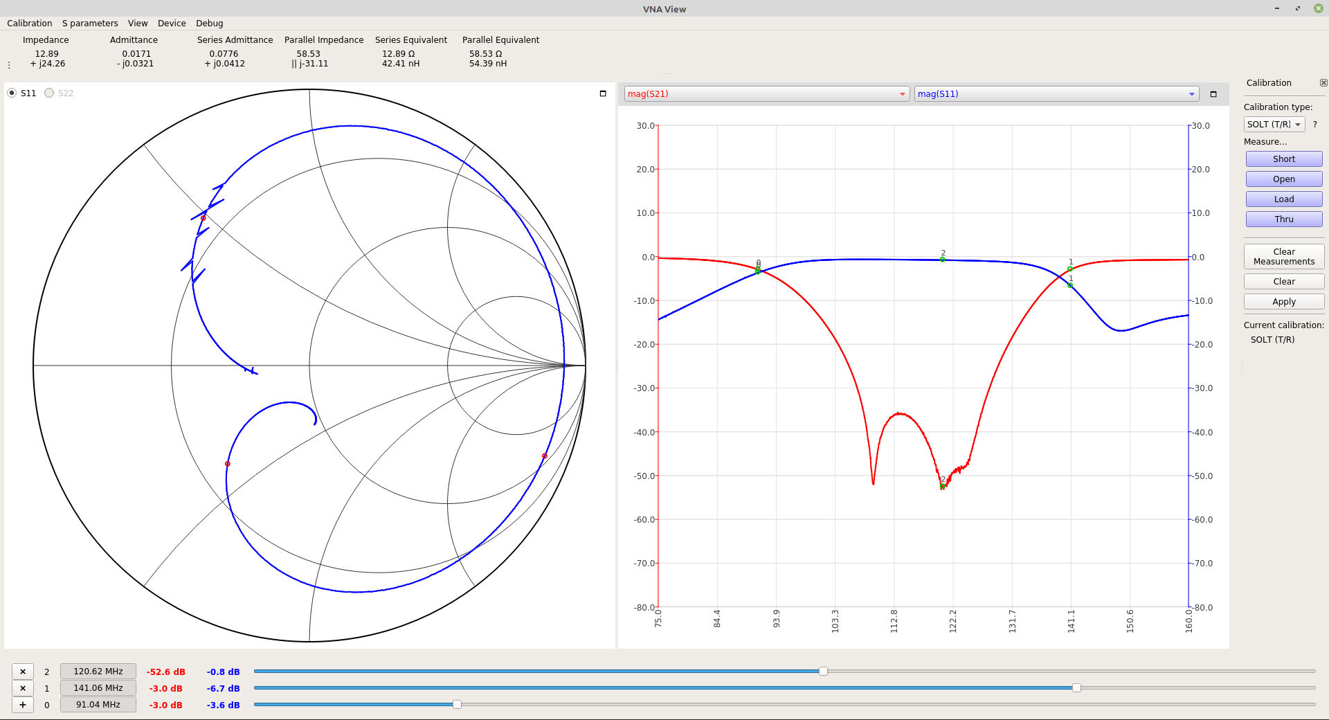
Filter VNA Performance
The response of the filter isn’t bad at all! It’s shifted up a little high on the scale, with the lower -3dB point being at 91MHz rather than 88MHz, but it does indeed chop out the broadcast band by -52dB. The high -3dB point is at 141MHz.
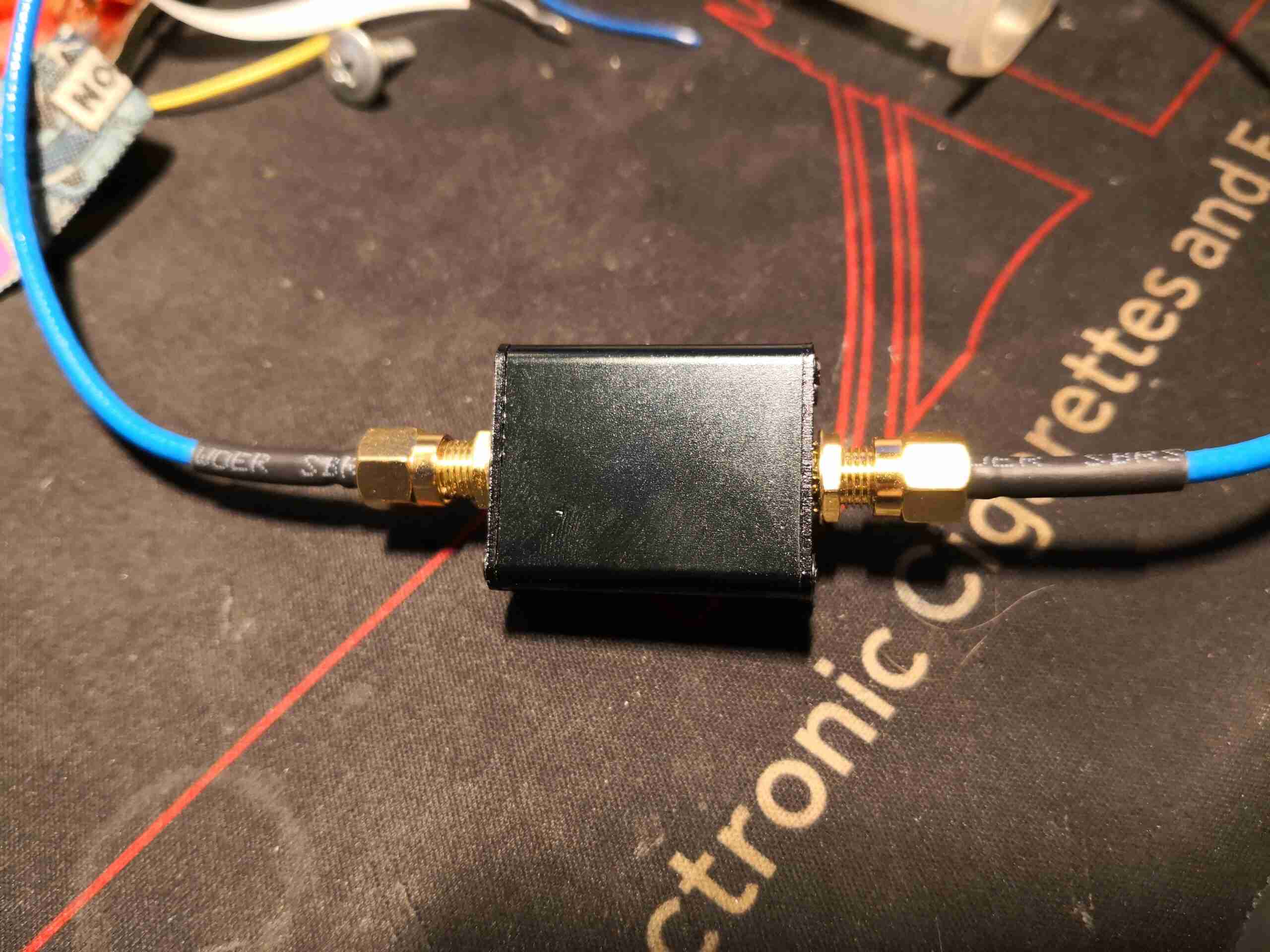
Let’s look at a commercial filter now, here’s the unit below, it’s definitely been size & cost optimized!
Commercial Stopband Filter
The box is tiny, not much bigger than the SMA connectors!
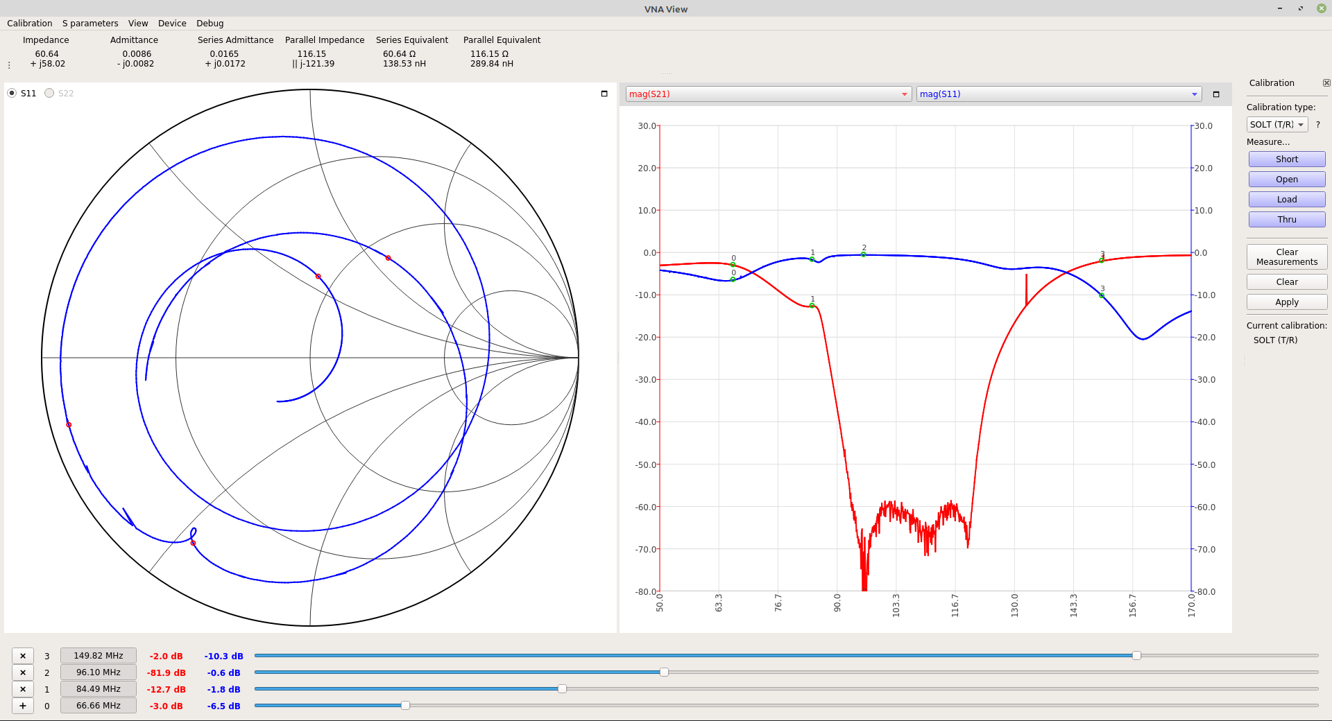
Commercial Filter VNA Characteristics
Looking at the plot from the NanoVNA, it’s clear this is also a Type 2 Chebyshev, but it’s more effective. This has a stopping power of -82dB, it’s also better centred.
Commercial Filter PCB
The board easily removes from the external shell. The SMA connectors are edge launch, which is good for maintaining impedance. There are a couple more stages of filtering in here than I put on my filter, which explains the much improved blocking characteristics. There does appear to be some damage though – there’s an inductor missing from the left side of the PCB. This is probably responsible for the odd response at the low end. There clearly was an inductor there, as the solder fillets are still present. Maybe this was removed at the factory as a form of tuning?
There’s quite a nice desktop app for the new NanoVNA v2, NanoVNA-Qt. It’s released as an AppImage for Linux, but unfortunately there is no version to run on a Pi supplied. The version below is built to run on the latest version of Raspbian (as of writing this, 2020-05-27).
Since the entire country is on Coronavirus lockdown at the moment, I figured it was time to get round to finishing off a couple of small blog posts while waiting for the restrictions to be lifted 😉
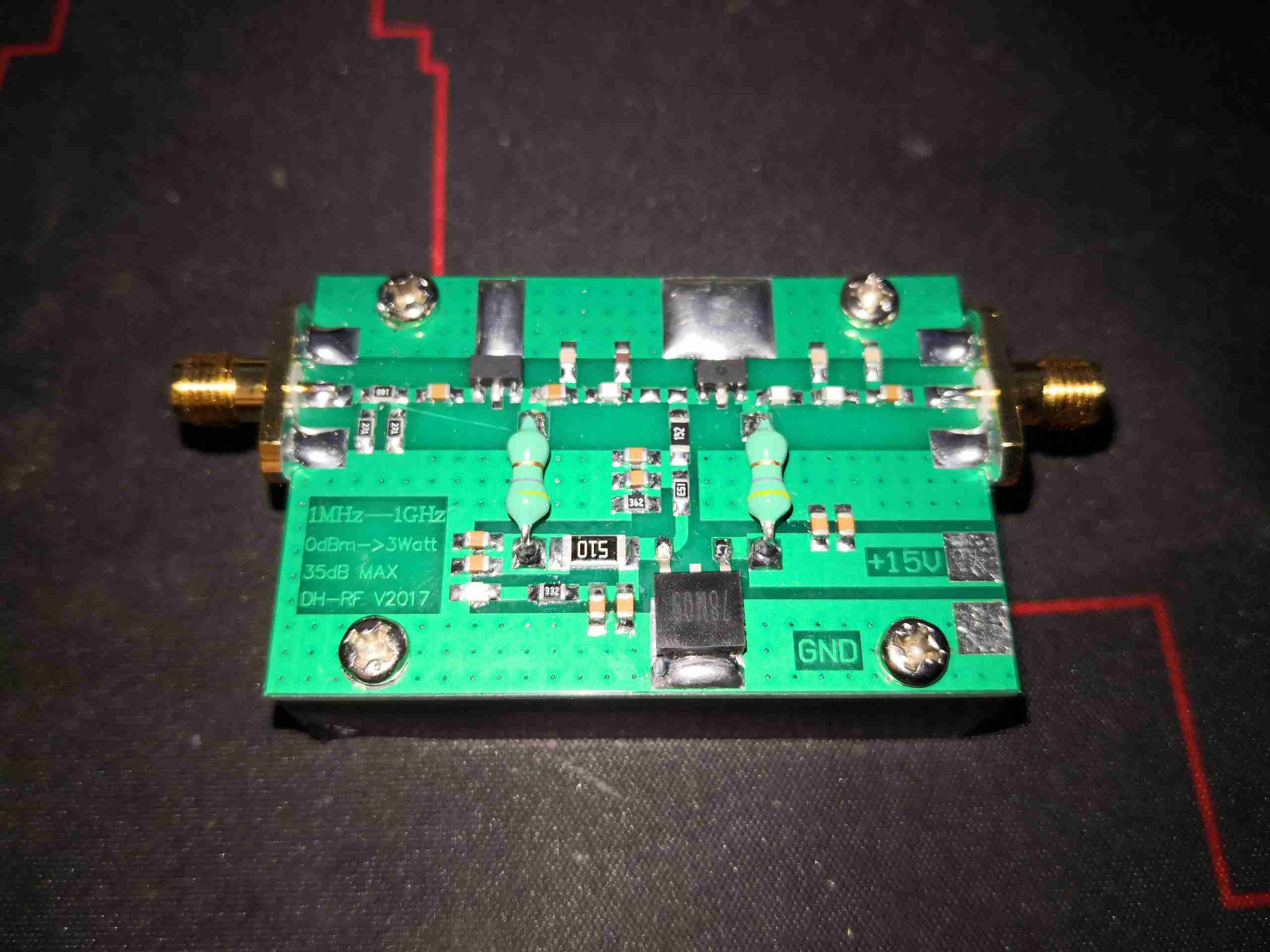
3W 1GHz Amplifier
This is a small two-stage linear amplifier module available on eBay fairly cheap for SDR operation.This unit claims 3W (34.8dBm) power output at 0dBm input, however not surprisingly, this amplifier isn’t quite flat across the frequency range.
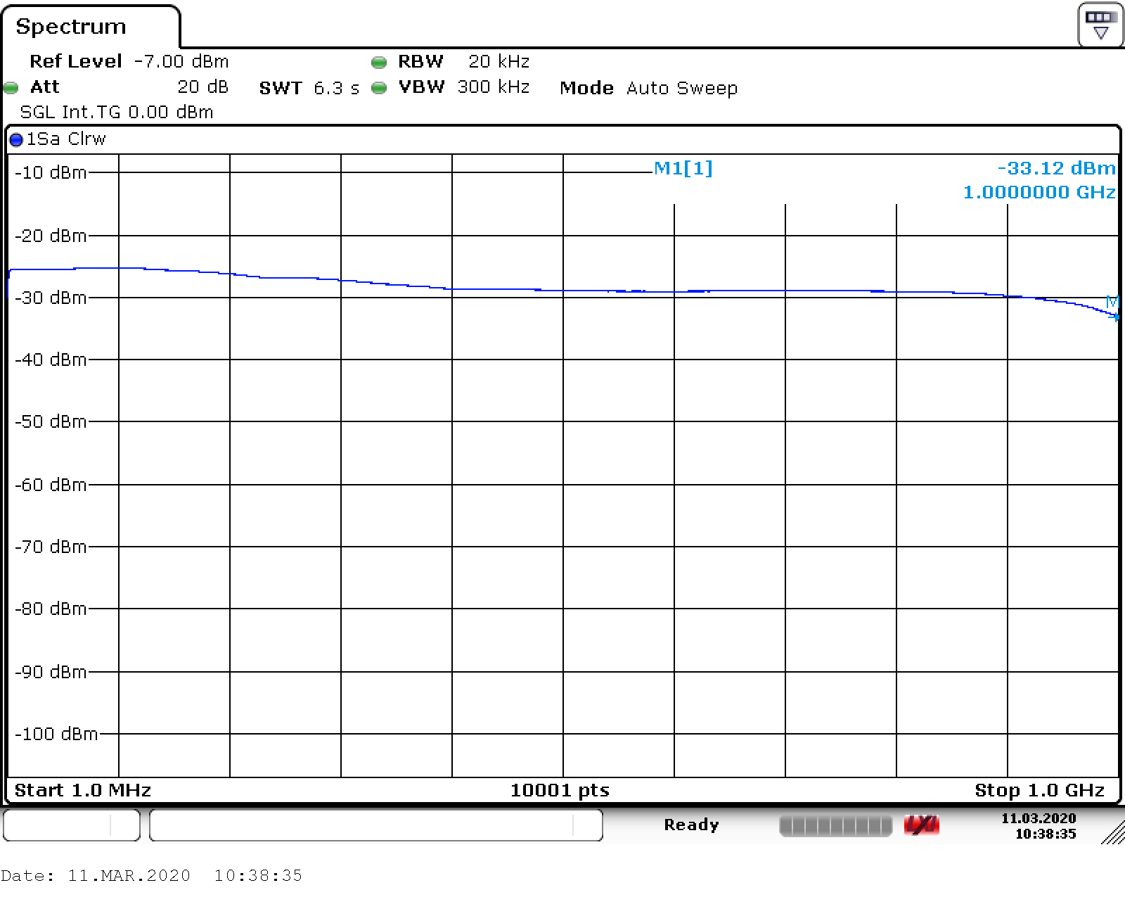
Frequency Response
Here’s the readout from an R&S FSV7 spectrum analyser. The amplifier is being driven from the analyser’s tracking generator at 0dBm, and the output is fed back into the input via 60dB of external power attenuation. The span here is 1MHz-1GHz, and at the top end the frequency response is already beginning to drop off a cliff – the 1GHz rating appears to be the 3dB down point. The rated output power of 3W appears to only be attainable below 100MHz for the rated 0dBm input, after that it drops pretty quickly to about -3dB.
Frequency
Output - dBm
Output - W
100MHz
34.74
2.97
144MHz
34.4
2.75
200MHz
33.81
2.40
315MHz
32.59
1.81
433MHz
31.46
1.39
500MHz
30.91
1.23
600MHz
30.87
1.22
700MHz
31.04
1.27
800MHz
30.95
1.24
900MHz
30.24
1.05
1000MHz
26.86
0.48
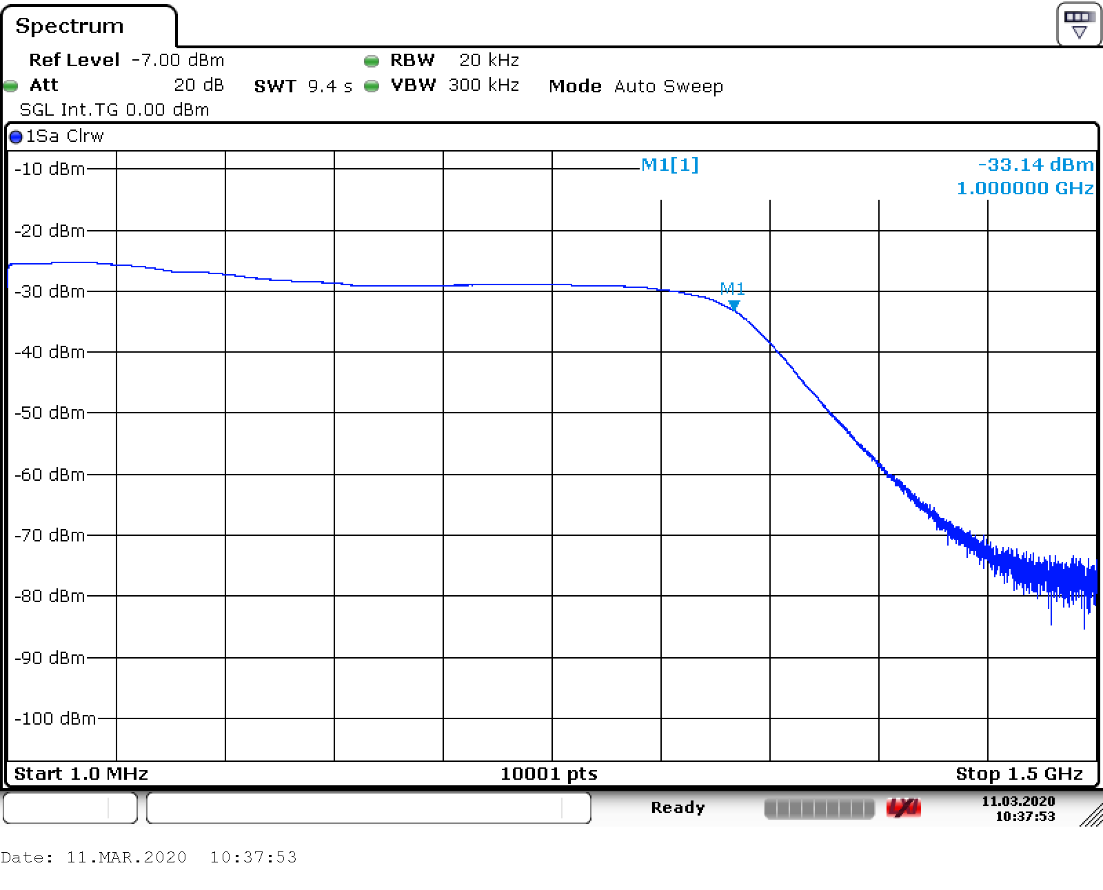
Extended Span
Extending the frequency span of the analyser shows the roll off at high frequency – this module really isn’t usable above the rated frequency range.
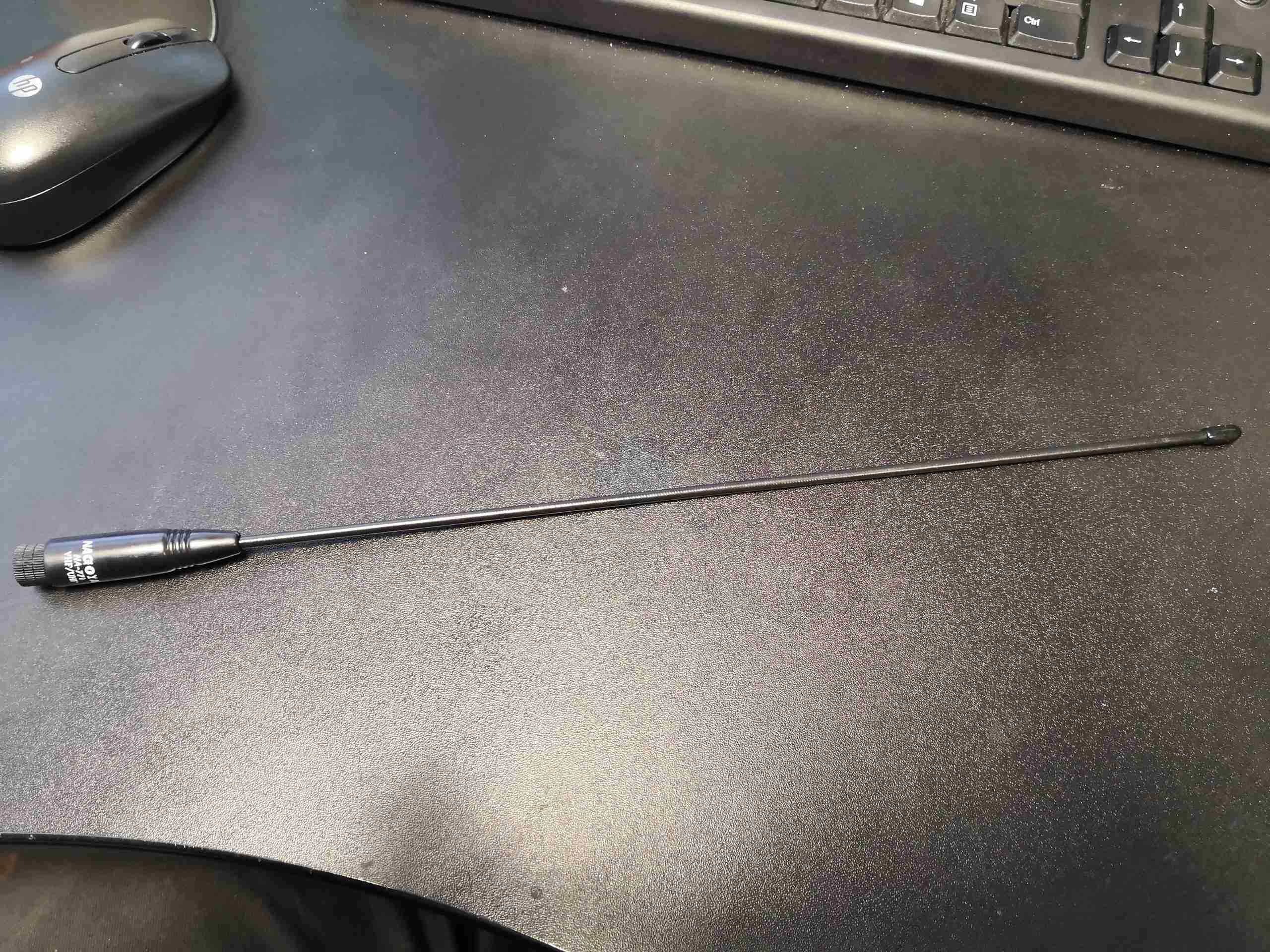
eBay yet again doesn’t disappoint when it comes to fake kit. Here is a claimed dual-band antenna, a Nagoya NA-771. This is supposed to be good for both 144MHz & 433MHz.
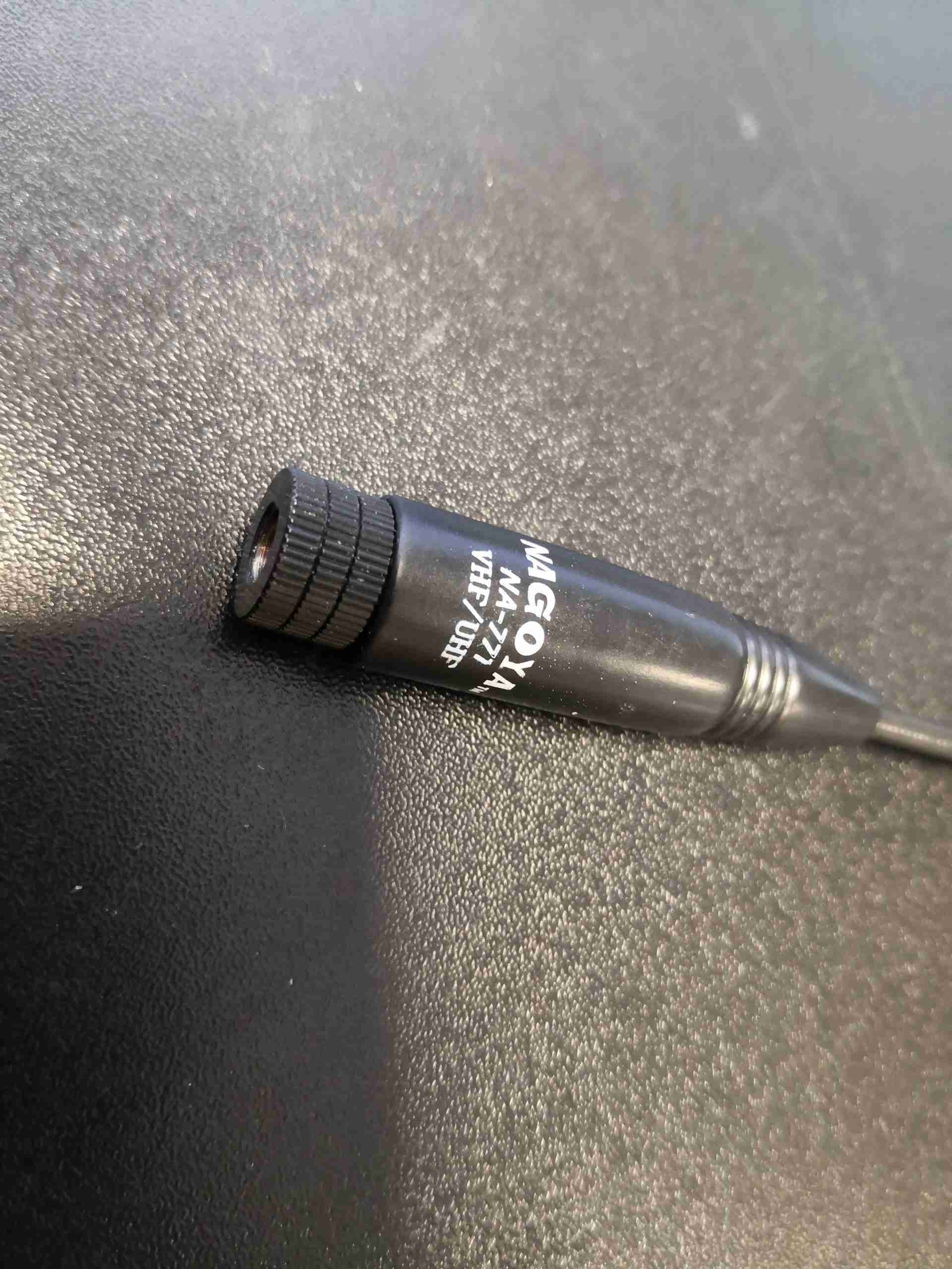
Base Logo
The first clue is in the logo printing on the base, it’s not straight, or even. The base isn’t aligned correctly with the connector either, being glued on at a janky angle.
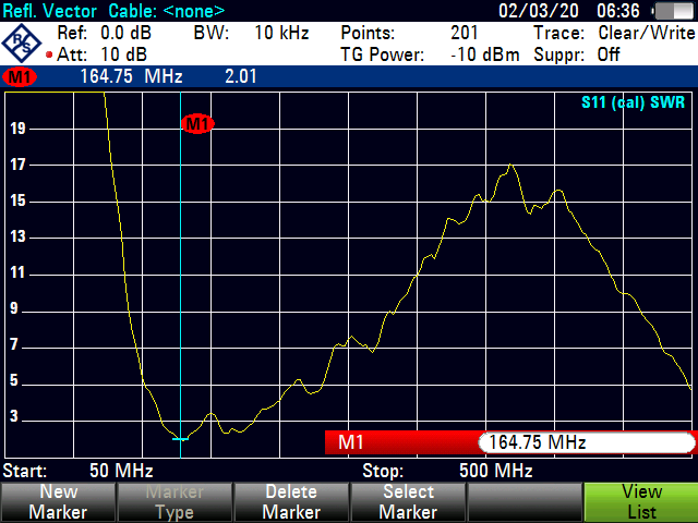
165MHz433MHz
Beyond looks, a network analyser really shows the problems. Here’s a scan from 50MHz to 500MHz. There’s a fairly decent SWR of 2.01:1 at 164MHz (the tuning is still off, it’s supposed to be at 144MHz), but the SWR at 433MHz is 13:1!
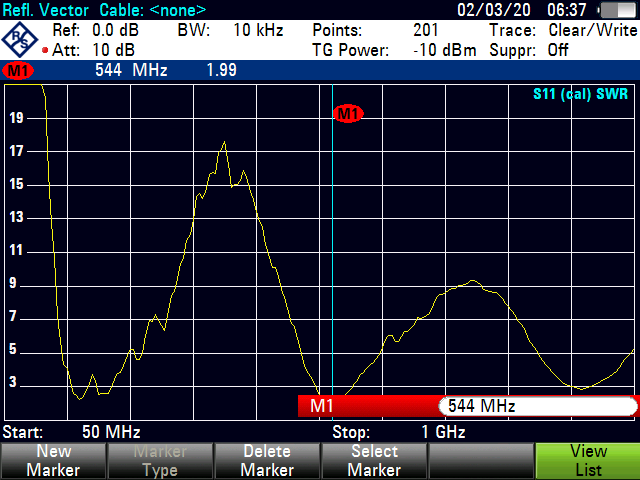
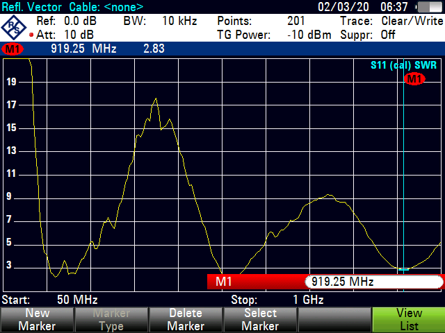
544MHz920MHz
Extending the range to 1GHz does show another couple of resonant points, at 544MHz (1.99:1) & 920MHz (2.83:1), well outside the band that this antenna is supposed to work to.
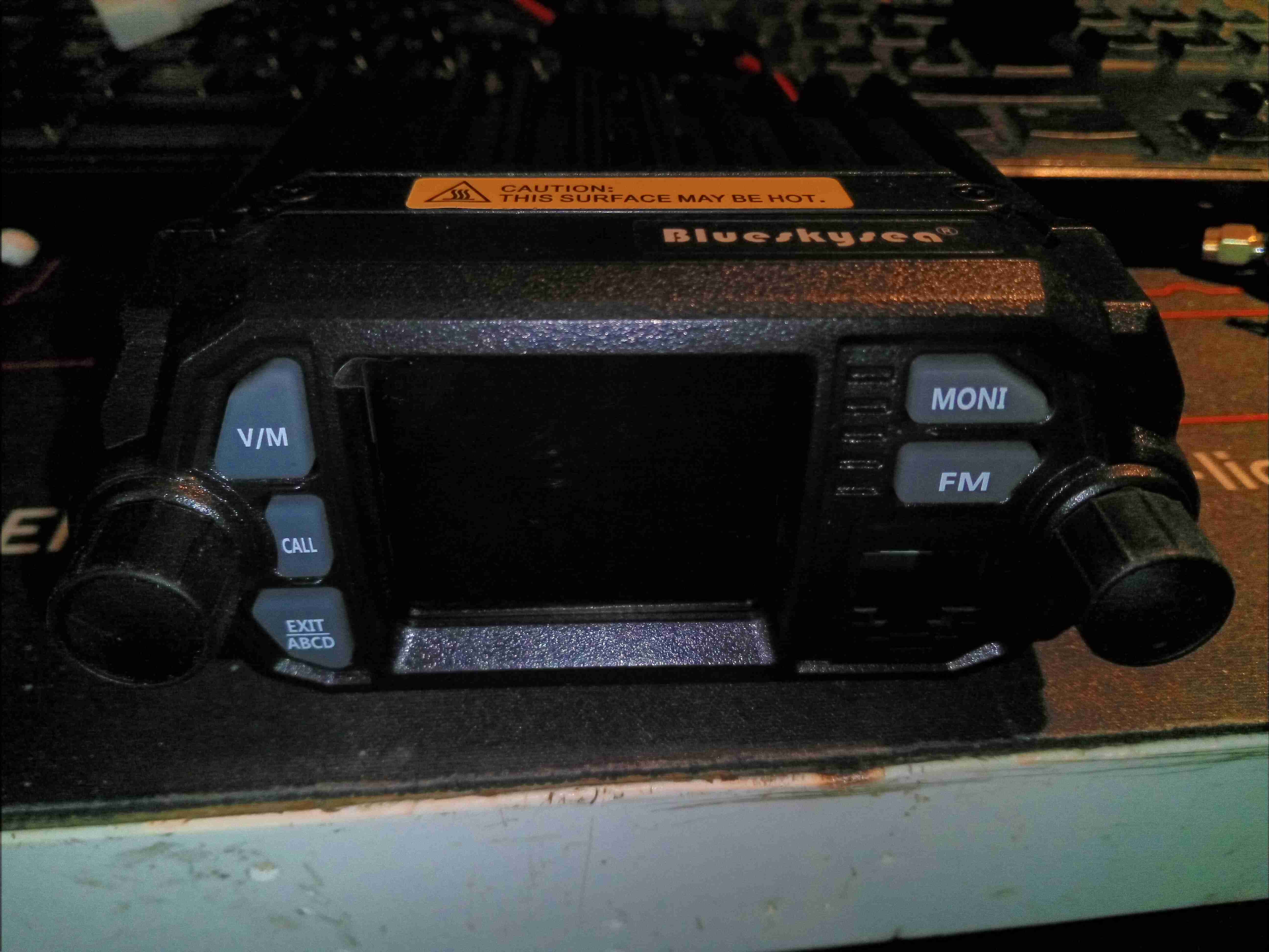
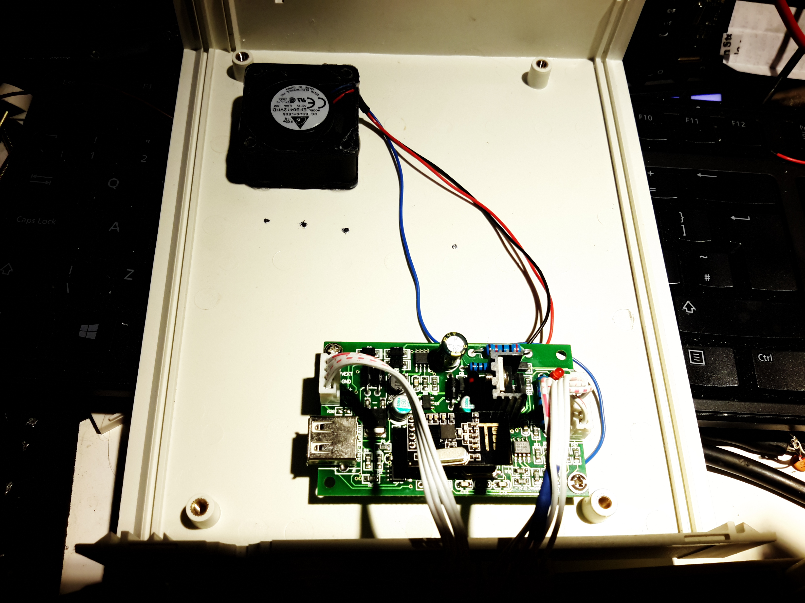
Here’s a miniature-sized mobile rig, which I purchased from eBay to fit in the car – my main Wouxun radio is far too big to fit under the dash! This unit is not much bigger than a UV-5R and cost less than £60! The front panel has a colour TFT LCD for the user interface, with a standard pot for volume, and rotary encoder for menu actions. Most of the controls are actually on the DTMF PTT mic, but some things are operable from the front panel.
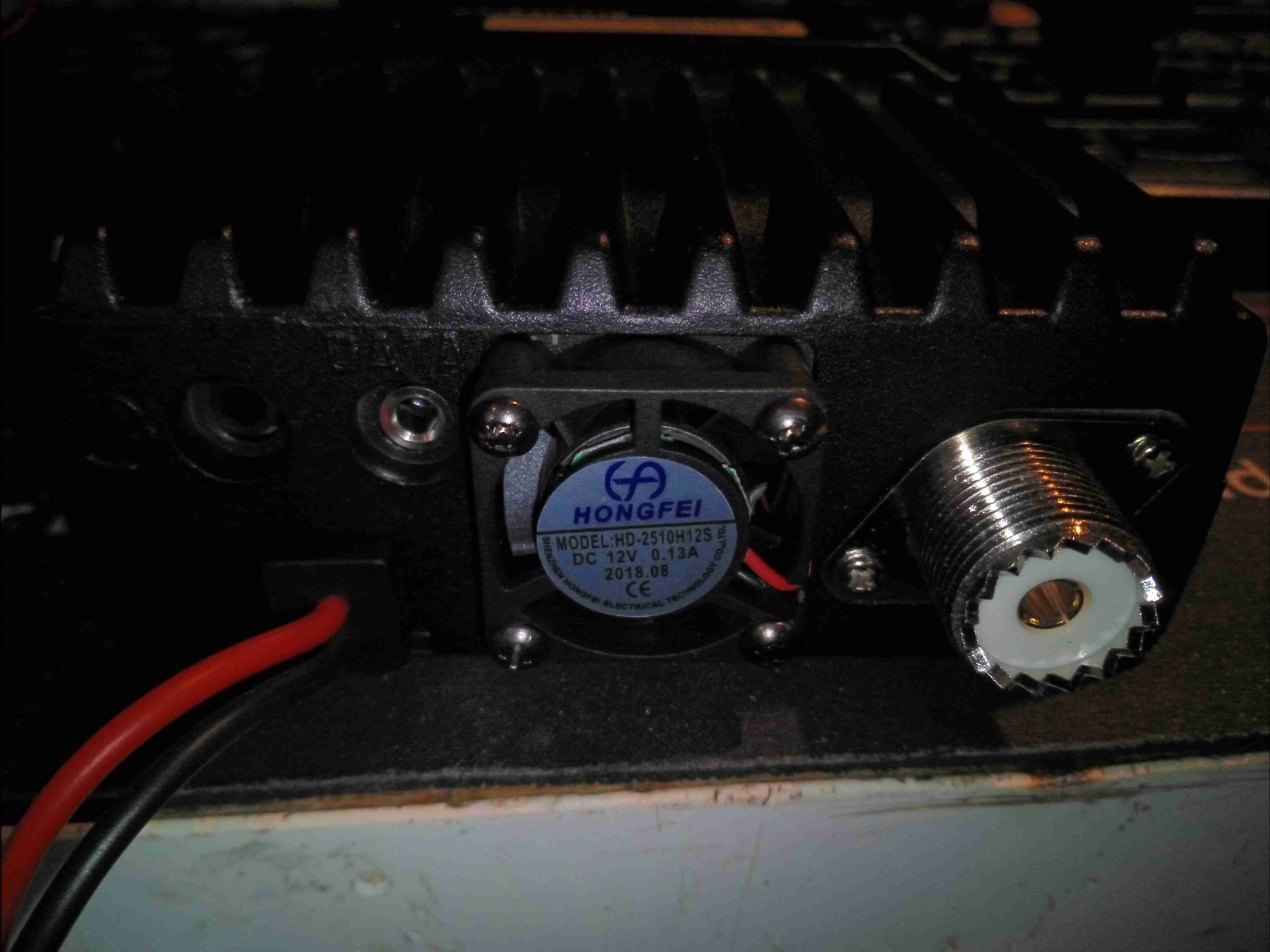
Rear Panel
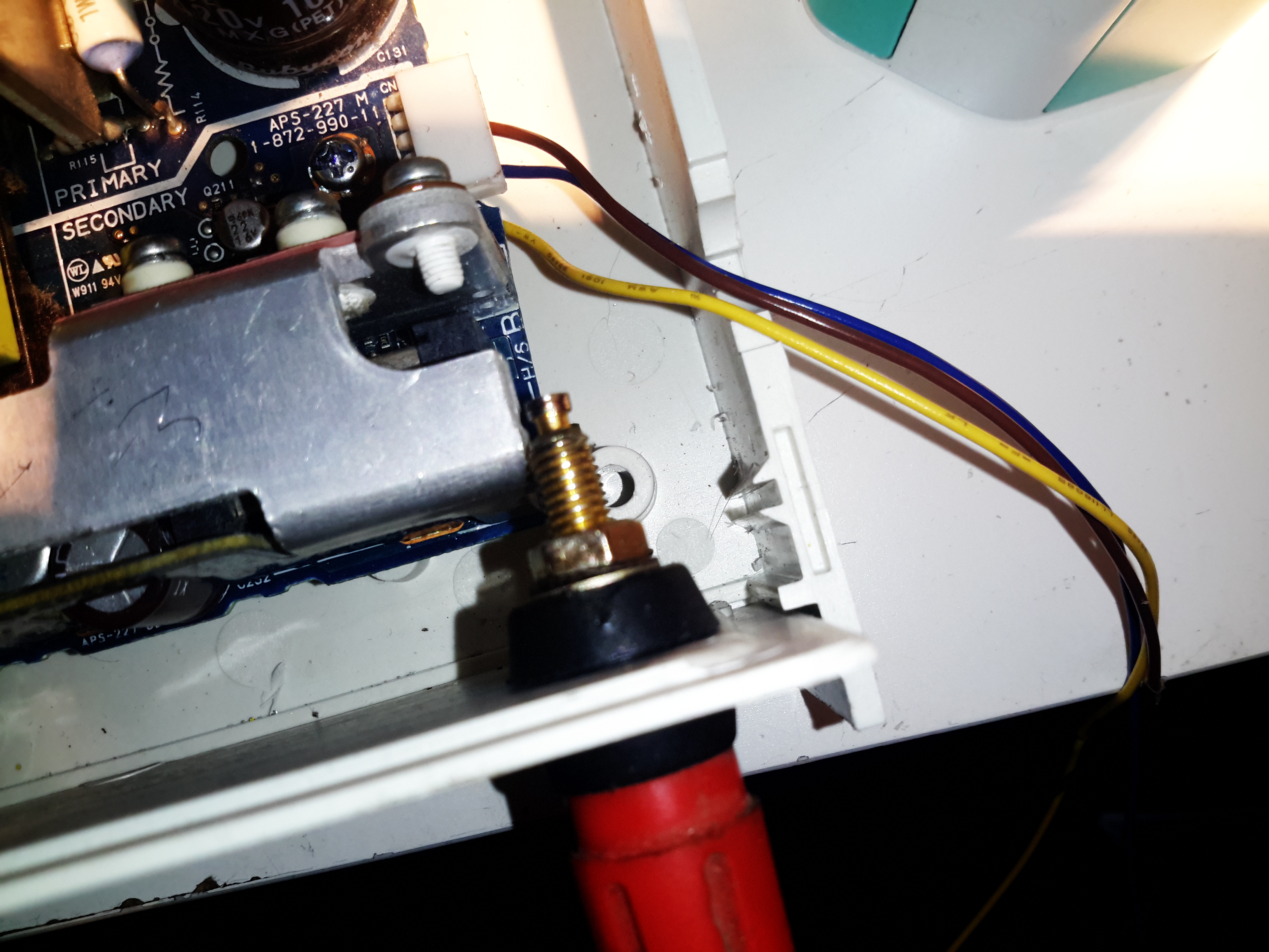
The rear panel has a small fan to cool the internal RF power amp, and a PL-259 connector for the antenna connection. This will be the first thing to be replaced, with an N-Type. There’s also a headset connector on the back, along with a 3.5mm TRS jack for serial data – very important on this radio for programming, as the interface is abysmal in this department ;).
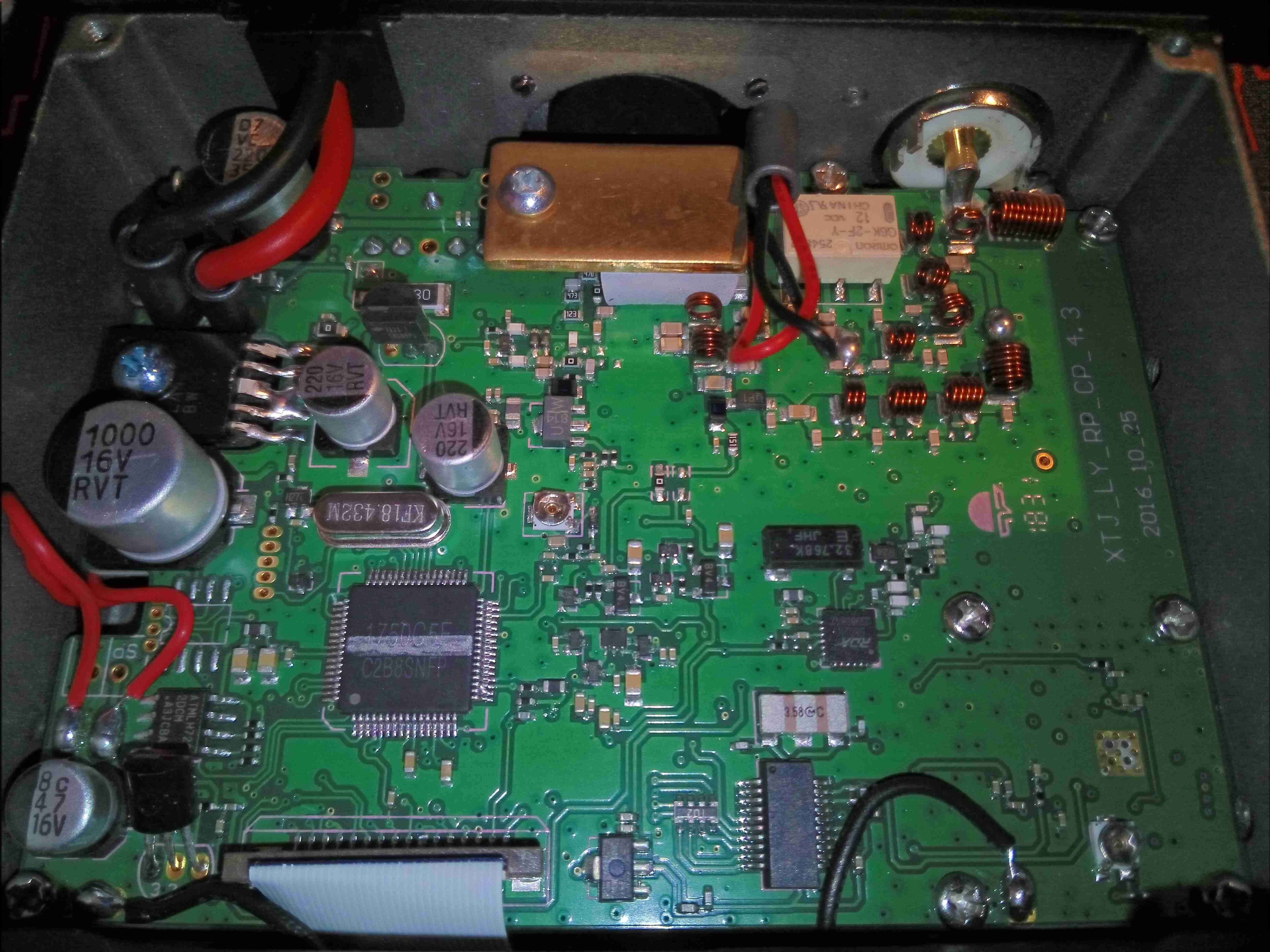
Internal View
Popping the plastic bottom cover off allows access to the internals. There’s a single PCB in here with a double-sided load. Unfortunately the PCB is too difficult to remove from the casing without damaging anything, so only this side to be seen! On the top though is the main system microcontroller, the broadcast FM receiver, voltage regulation and the RF output stages.
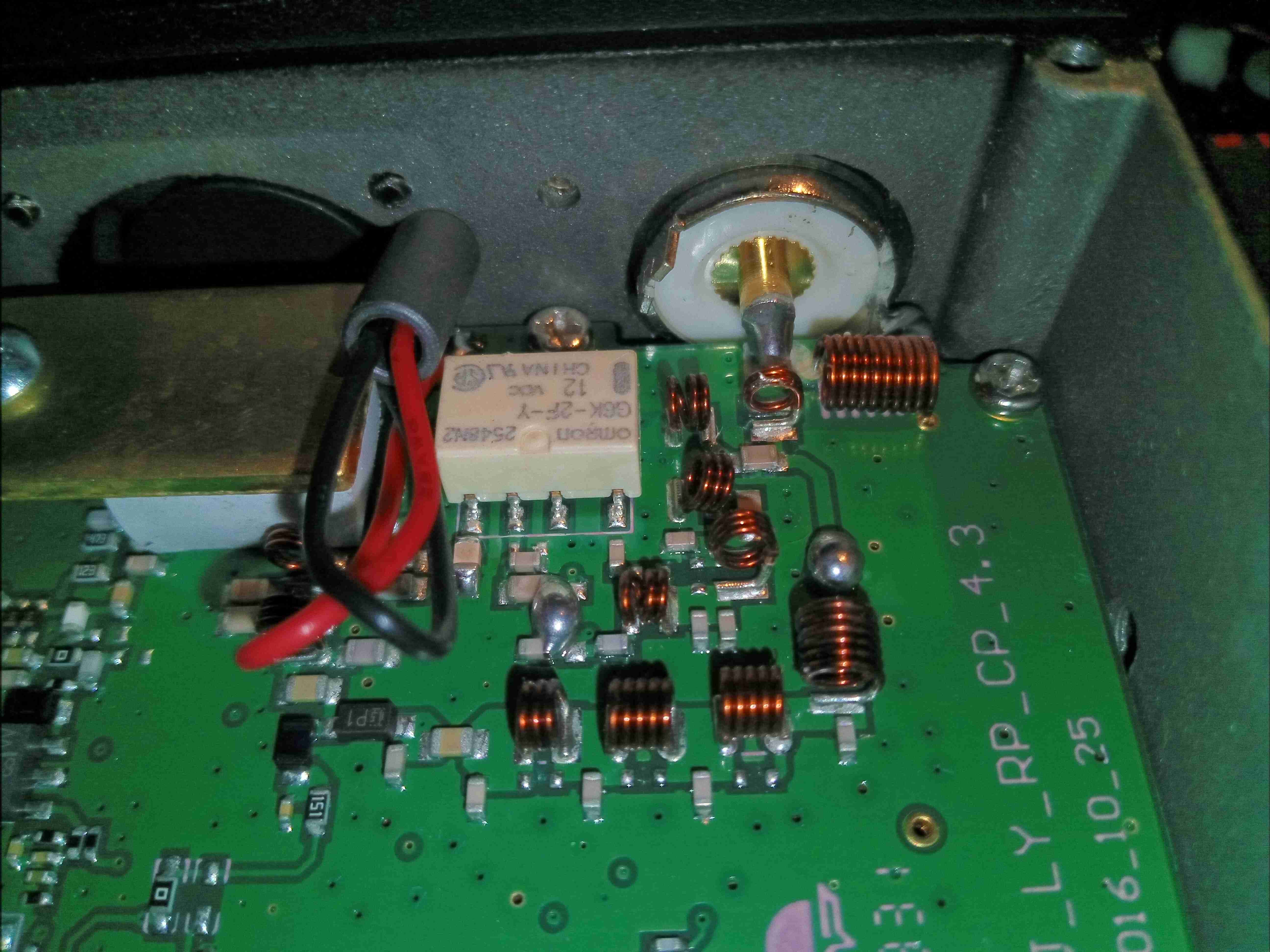
RF Output
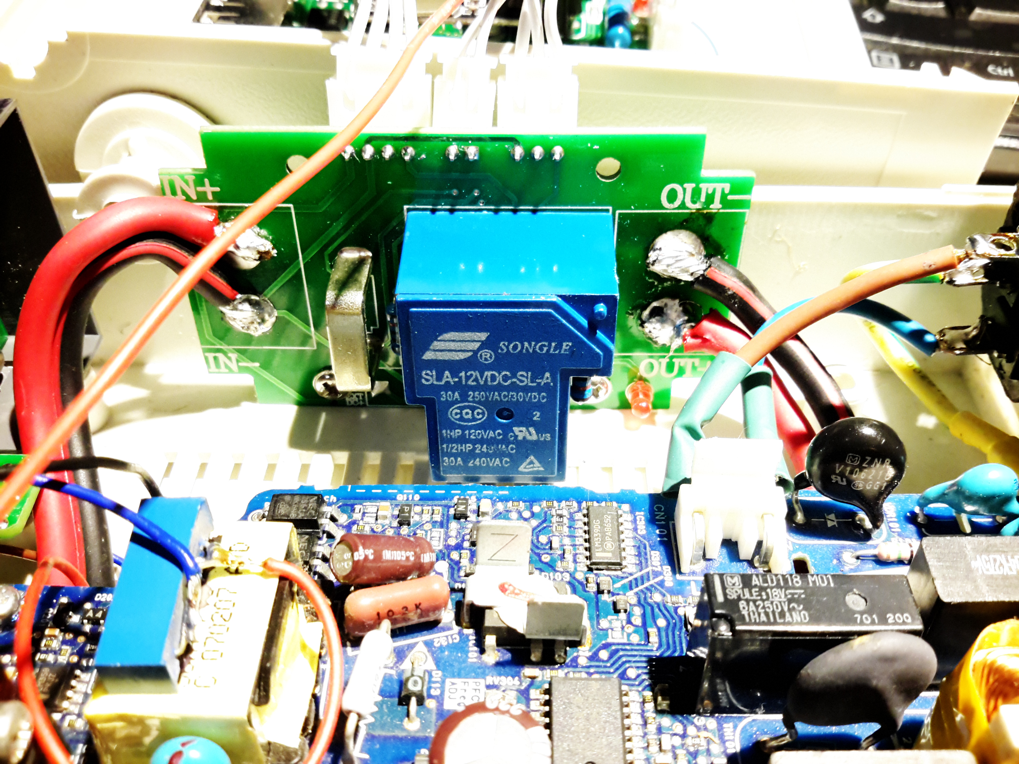
The RF output filters are tucked into a corner of the board near the antenna connector, with a small relay to switch between VHF & UHF. My concern with this relay is that it’s not intended for RF use, and is in fact a general purpose relay. This would have been designed into the unit as a price reduction measure. Under the brass plate & thick SIL pad is the main RF output transistor. The external fan leads also pass very close to the RF output stage, so they may end up radiating some RF from the back of the unit, despite the ferrite bead on the leads.
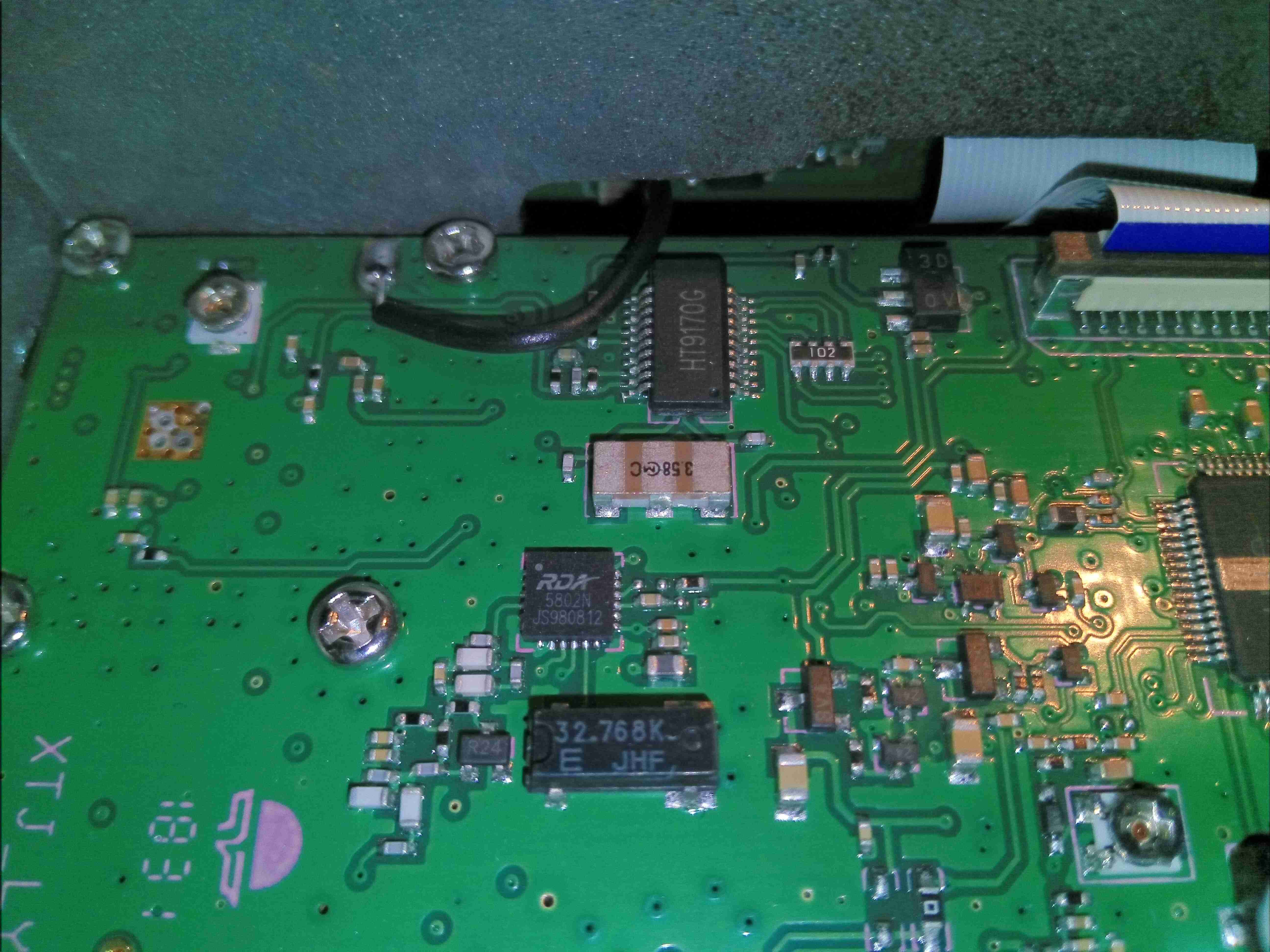
FM Receiver & DTMF Receiver
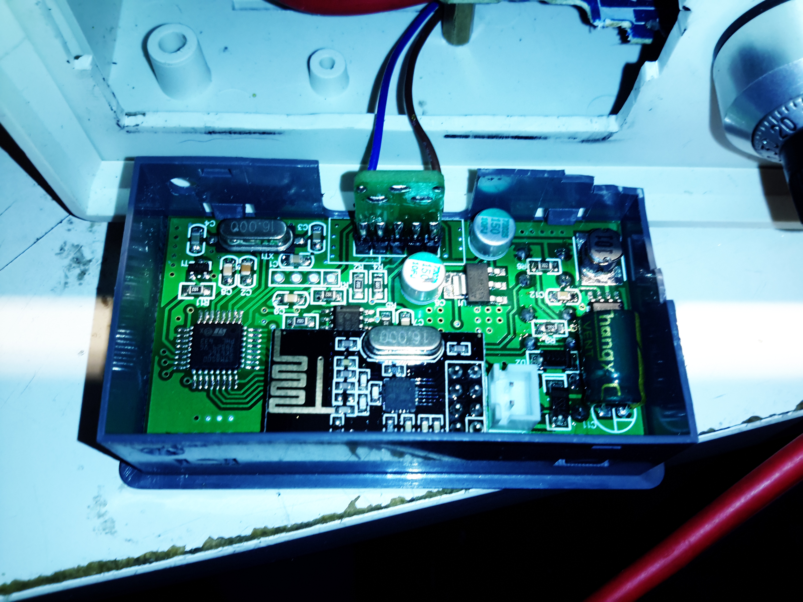
Just behind the front panel is the broadcast FM receiver, an RDA5802, with it’s 32.768kHz clock crystal. Just above that is the DTMF receiver & decoder, used in most Chinese radios, with it’s ceramic resonator. There’s a couple of unmarked pots on the board, but I am not certain what their function is.
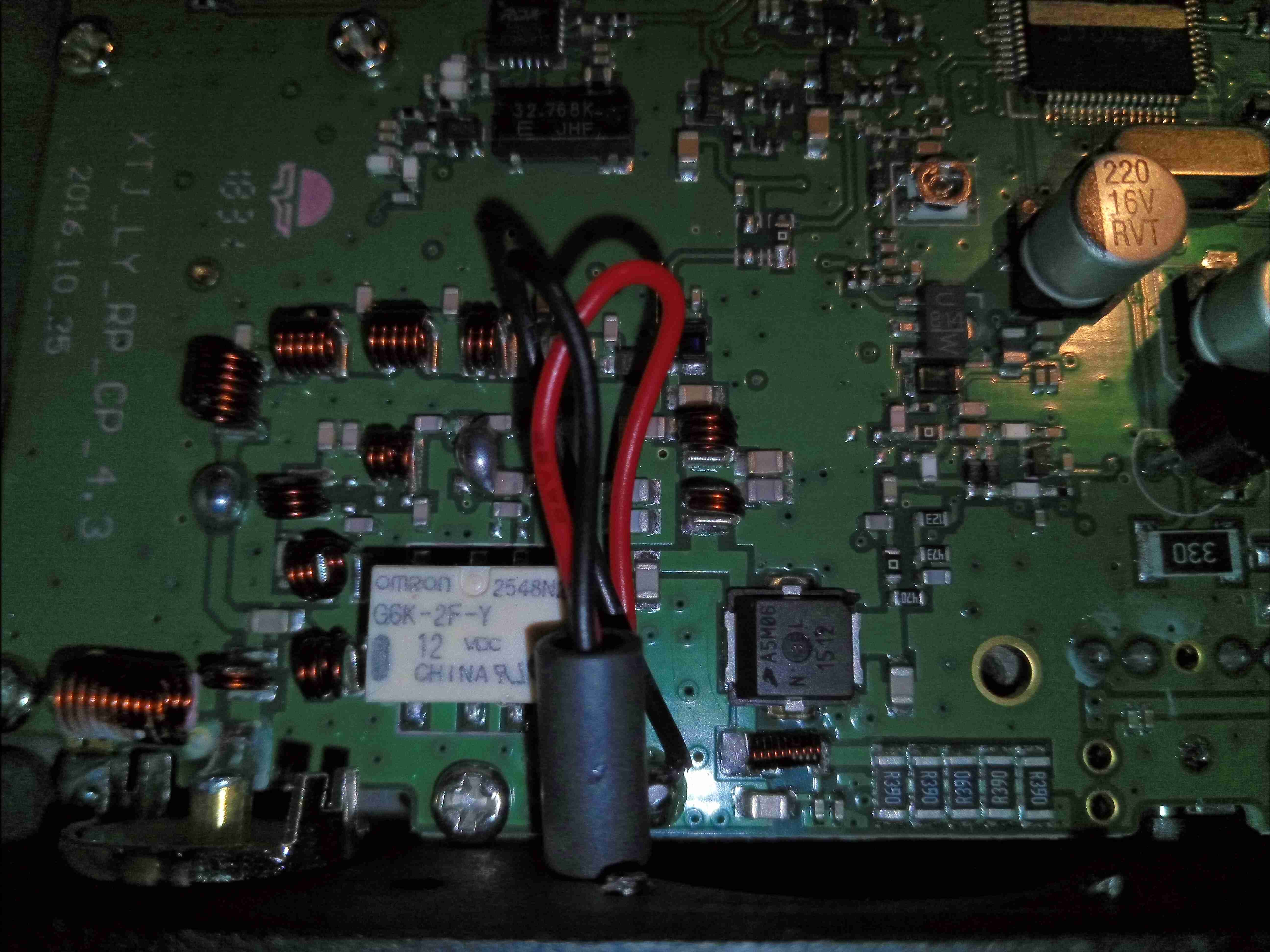
RF Output Stage
Here’s the RF output stage, with the “heatsink” removed. I’m concerned on several fronts with this part – the heatsinking provided by a small brass plate and thick SIL pad is going to be poor at best, but looking at the datasheet for the main RF transistor, an AFT05MS006NT1 RF LDMOS N-Channel Lateral MOSFET from NXP shows some alarming numbers. Grab the full datasheet [download id=”7839″].
Remember that this radio is intended for mobile use in vehicles – the electrical systems of which can in a normal operational state rise to 14.8v.
This transistor is intended for handheld radio use, with an operational voltage of 7.5v, and absolute maximum ratings of 12.5v! Even when used on a regulated 13.8v PSU, the absolute maximum rating for the transistor is being exceeded.
At the very least, I would expect the life of the radio to be shortened due to this problem, and at worst the transistor may catastrophically fail in service, damaging the radio.
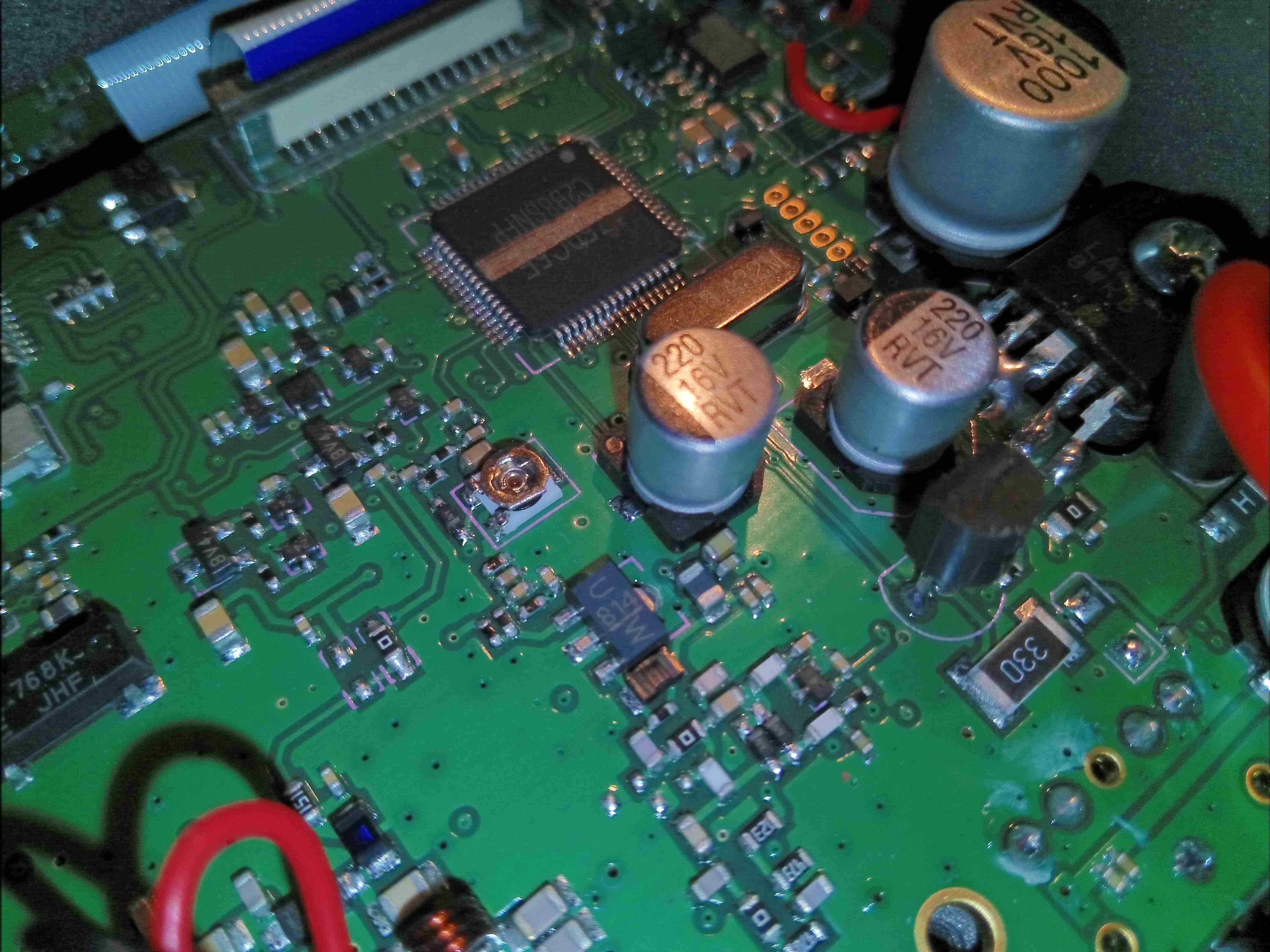
Main Microcontroller
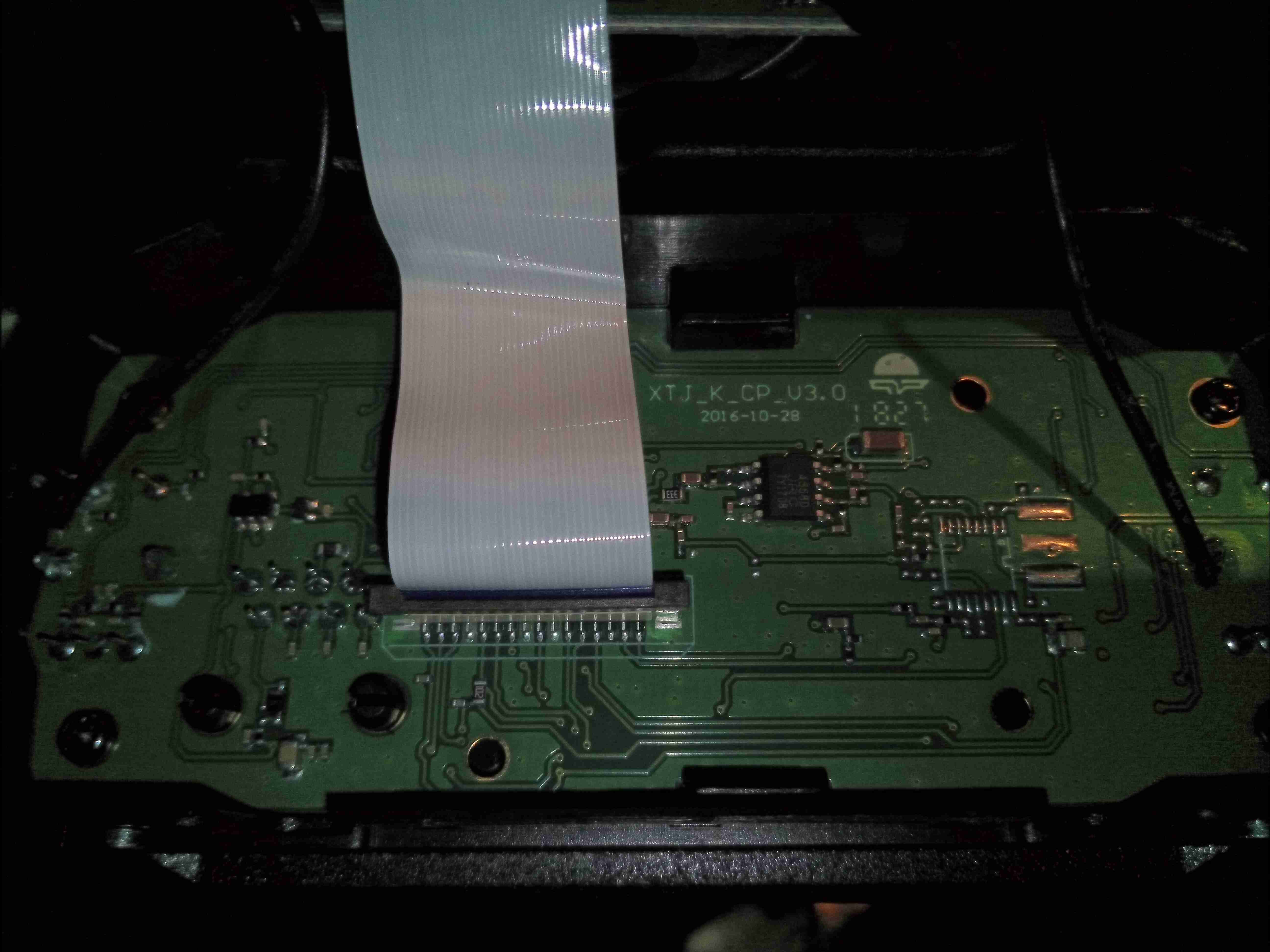
The main microcontroller is a Renesas R8C series device, with quite a few peripherals. It is accompanied by it’s clock crystal, and a programming header. An FFC cable vanishes off to the front panel PCB for driving the LCD & connecting up the user controls & mic connector. Just to the right is the main voltage regulation section for the electronics, minus the RF output stage, which is directly connected to the DC input bus.
Front Panel PCB
There’s not much on the front panel PCB, so I won’t bother taking it out of the frame, this is going to mainly be interconnects for the SPI/I²C driven LCD & analogue channels for the audio.
I’ll keep the blog posted with lifespan checks on this radio, as I’m definitely concerned about the power amplifier transistor, but other than that it seems to be an OK radio. The rotary encoder has zero debounce, so it doesn’t work properly, but this isn’t much of an issue when the radio is fully operable from the PTT mic.
Since I’ve discovered some nice high power PSUs in the form of Playstation 3 PSUs, it’s time to get a new Bench PSU Build underway!
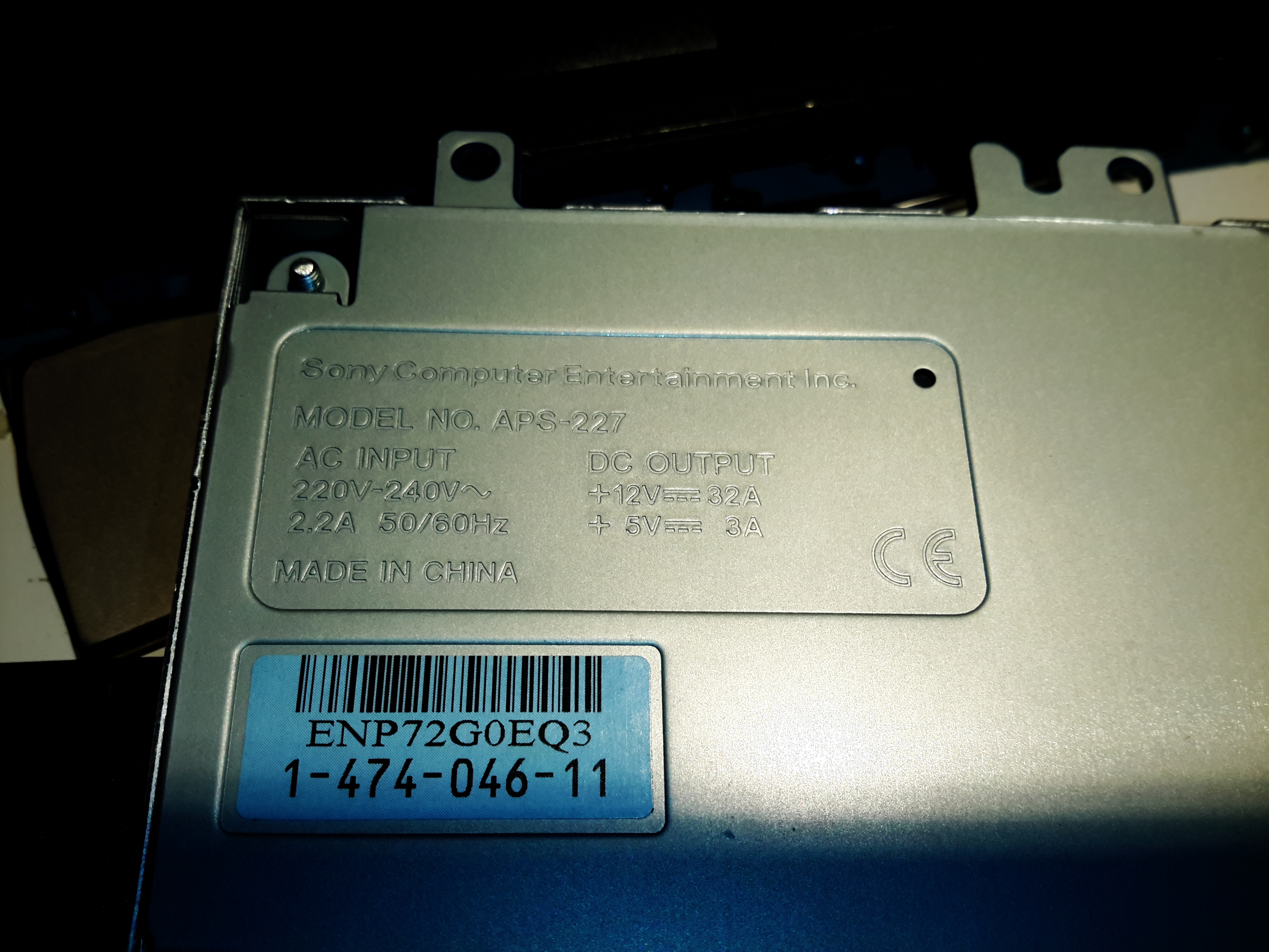
Specifications
I’ve gone for the APS-227 version as it’s got the 32A rail. This makes things slightly beefier overall, as the loading will never be anywhere close to 100% for long, more headroom on the specs is the result.
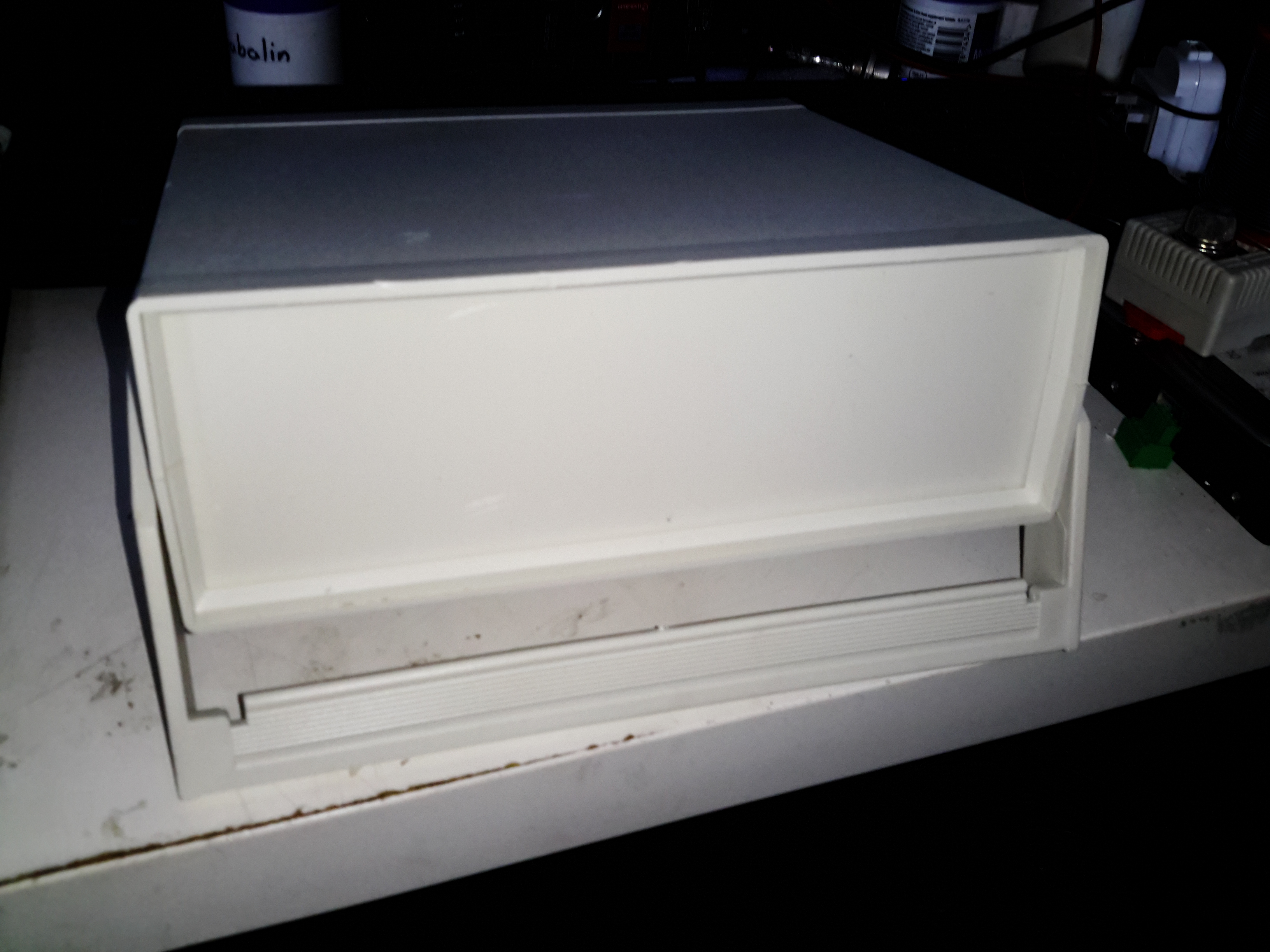
Desktop Instrument Case
The case I’ve chosen for this is an ABS desktop instrument case from eBay, the TE554 200x175x70mm. The ABS is easy to cut the holes for all the through-panel gear, along with being sturdy enough. Aluminium front & back panels would be a nice addition for a better look.
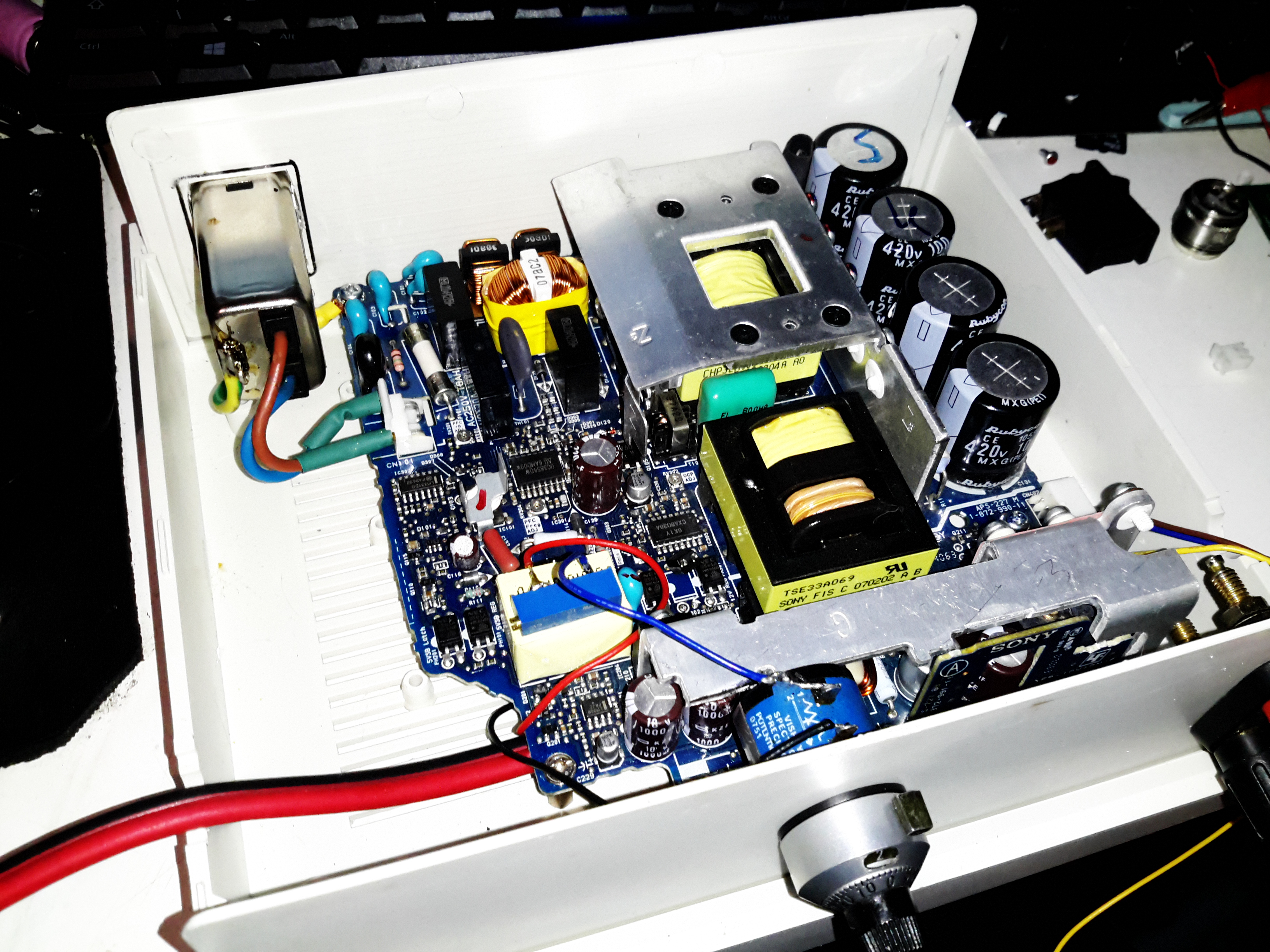
PSU Mounted
The PSU board is removed from it’s factory casing & installed on the bottom shell half, unfortunately the moulded-in posts didn’t match the screw hole locations so I had to mount some brass standoffs separately. The AC input is also fitted here, I’ve used a common-mode filter to test things (this won’t be staying, as it fouls one of the case screw holes). The 40A rated DC output cable is soldered directly to the PCB traces, as there’s no room under the board to fit the factory DC power connector. (This is the biggest case I could find on eBay, and things are still a little tight). Some minor modifications were required to get the PCB to fit correctly.
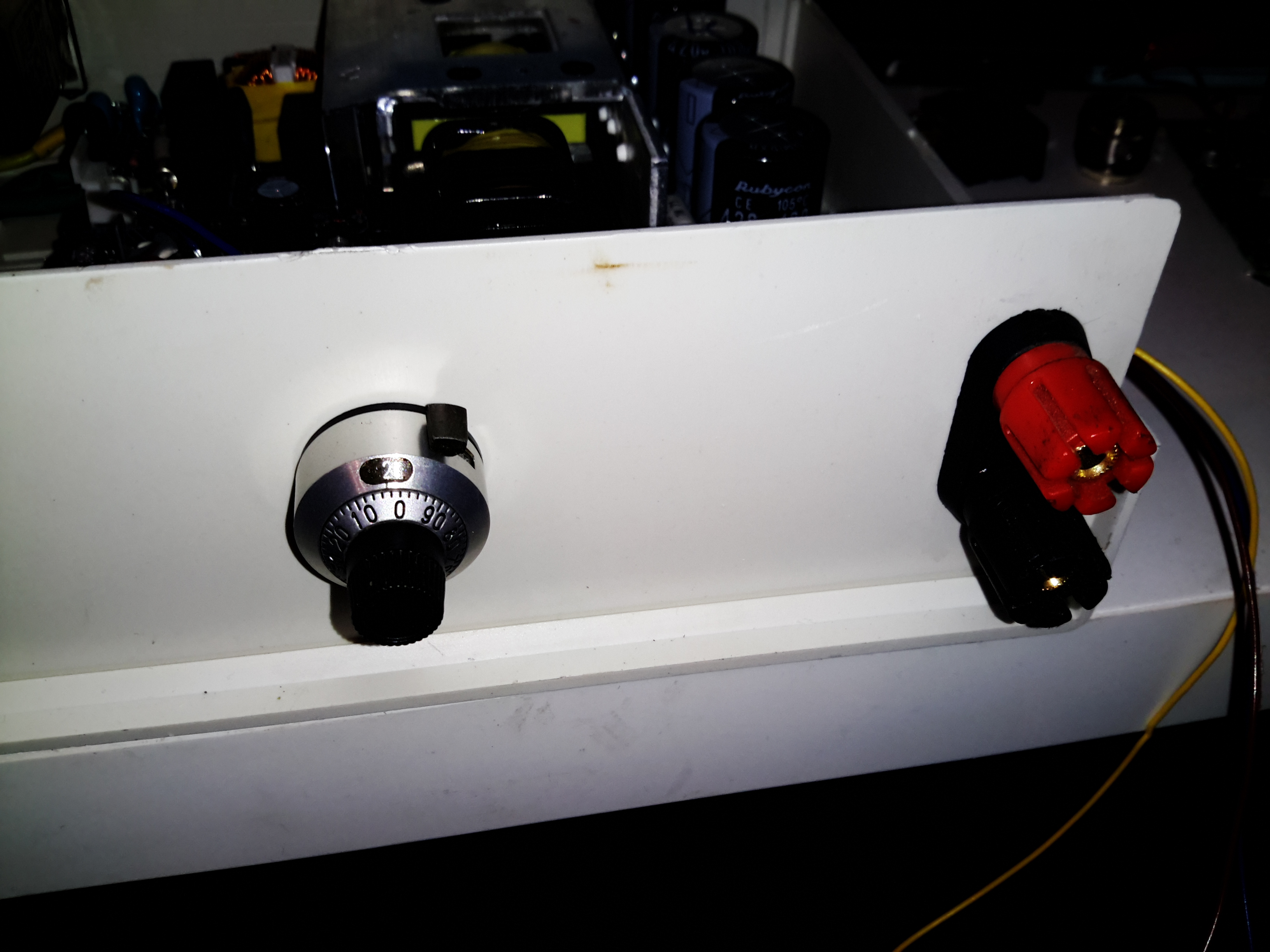
Output Terminals & Adjuster
I decided to add some limited voltage adjustment capability to the front panel, I had a 100Ω Vishay Spectrol Precision 10-turn potentiometer in my parts bin, from a project long since gone that just about fits between the panel & the output rectifier heatsink. The trimpot I added when I first posted about these PSUs is now used to set the upper voltage limit of 15 volts. (The output electrolytics are 16v rated, and are in an awkward place to get at to change for higher voltage parts). The binding posts are rated to 30A, and were also left over from a previous project.
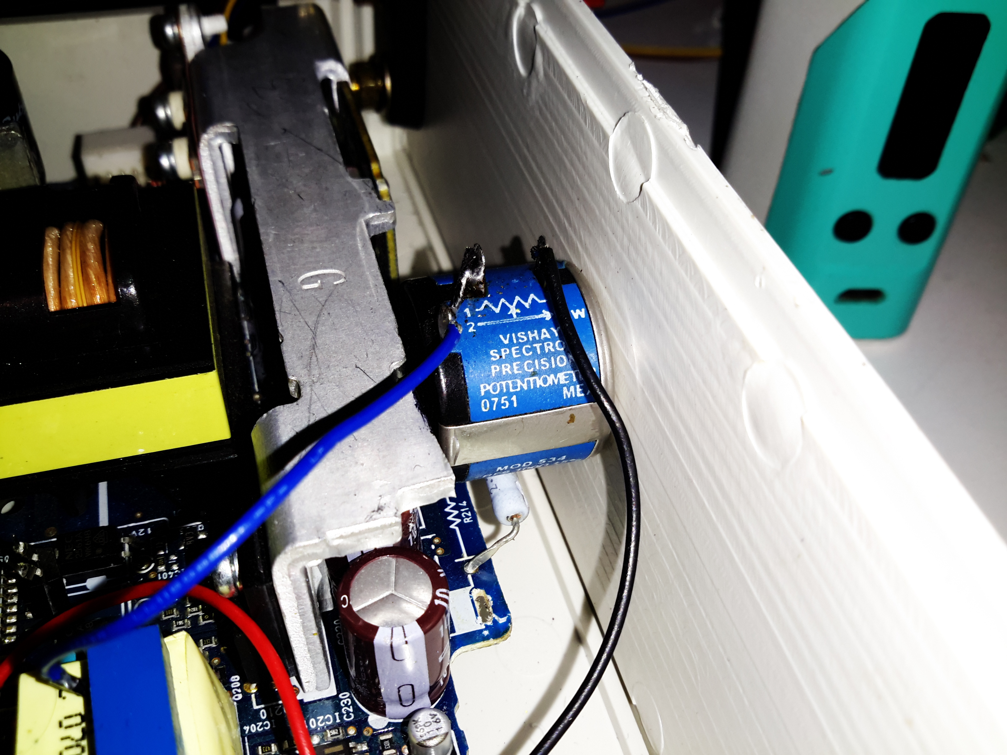
Vishay Spectrol 10-Turn
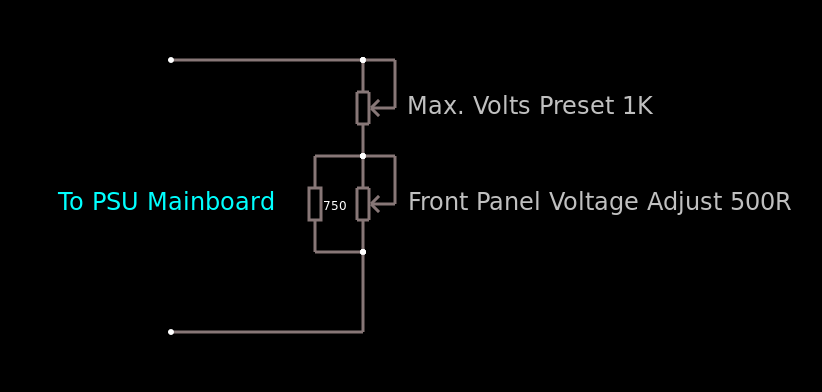
Addon Regulator Components
This front panel potentiometer is electrically in series with the trimpot glued to the top of the auxiliary transformer, see above for a simple schematic of the added components. In this PSU, reducing the total resistance in the regulator circuit increases the voltage, so make sure the potentiometer is wired correctly for this!
After some experimentation, a 500Ω 10-turn potentiometer would be a better match, with a 750Ω resistor in parallel to give a total resistance range on the front panel pot of 300Ω. This will give a lower minimum voltage limit of about 12.00v to make lead-acid battery charging easier.
I’ve had to make a minor modification to the output rectifier heatsink to get this pot to fit in the available space, but nothing big enough to stop the heatsink working correctly.
Terminal Posts
Here I’ve got the binding posts mounted, however the studs are a little too long. Once the wiring is installed these will be trimmed back to clear both the case screw path & the heatsink. (The heatsink isn’t a part of the power path anyway, so it’s isolated).
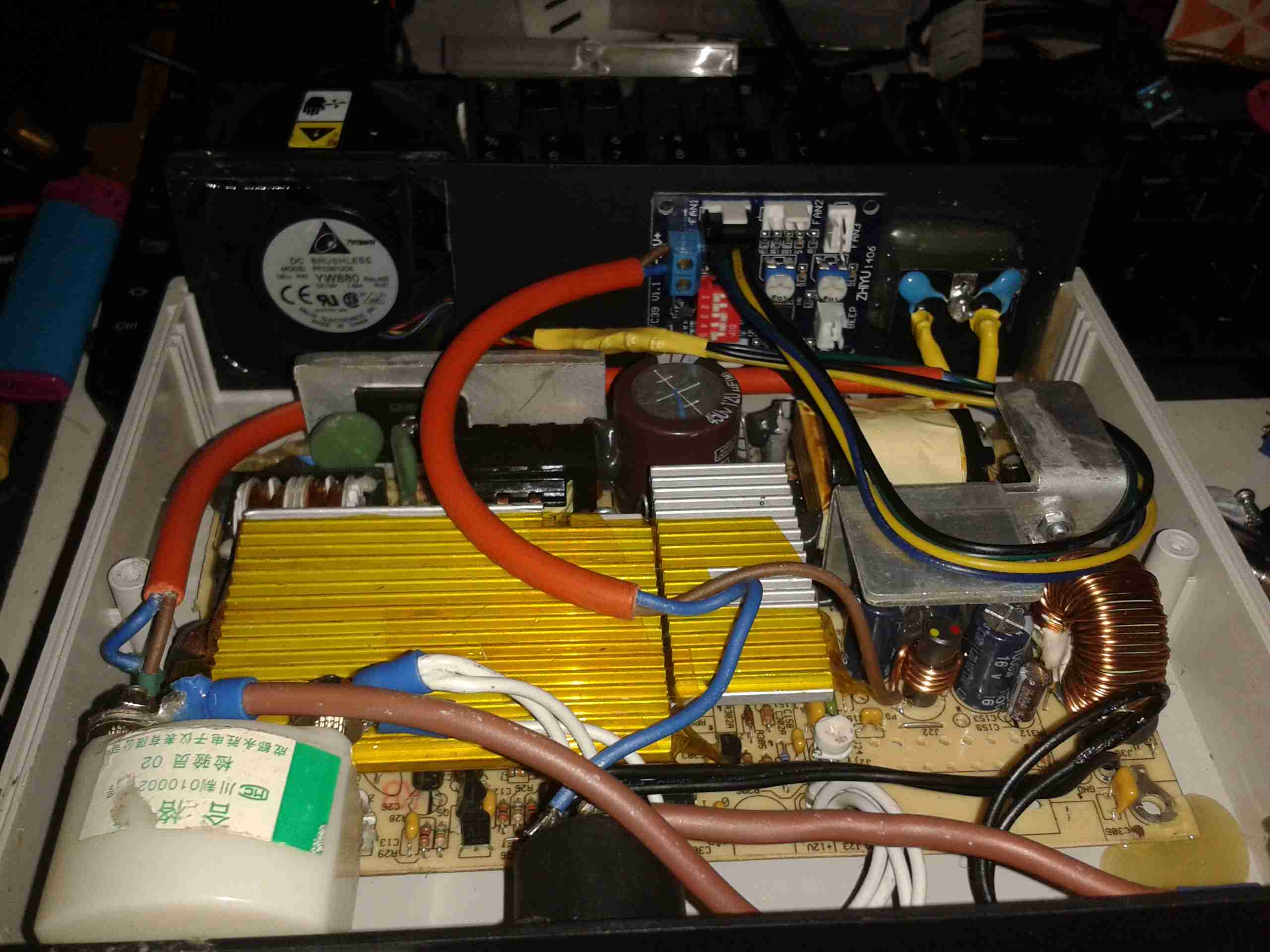
Power Meter Control Board & Fan
To keep the output rectifier MOSFETs cool, there’s a fan mounted in the upper shell just above their location, this case has vents in the bottom already moulded in for the air to exit. The fan is operated with the DC output contactor, only running when the main DC is switched on. This keeps the noise to a minimum when the supply doesn’t require cooling. The panel meter control board is also mounted up here, in the only empty space available. The panel meter module itself is a VAC-1030A from MingHe.
Meter Power Board
The measurement shunt & main power contactor for the DC output is on another board, here mounted on the left side of the case. The measurement shunt is a low-cost one in this module, I doubt it’s made of the usual materials of Manganin or Constantan, this is confirmed by my meansurements as when the shunt heats up from high-power use, the readings drift by about 100mA. The original terminal blocks this module arrived with have been removed & the DC cables soldered directly to the PCB, to keep the number of high-current junctions to a minimum. This should ensure the lowest possible losses from resistive heating.
Meter Panel Module
The panel meter module iself is powered from the 5v standby rail of the Sony PSU, instead of the 12v rail. This allows me to keep the meter on while the main 12v output is switched off.
PSU Internals
here’s the supply with everything fitted to the lower shell – it’s a tight fit! A standard IEC connector has been fitted into the back panel for the mains input, giving much more clearance for the AC side of things.
Inside View
With the top shell in place, a look through the panel cutout for the meter LCD shows the rather tight fit of all the meter components. There’s about 25mm of clearance above the top of the PSU board, giving plenty of room for the 40mm cooling fan to circulate air around.
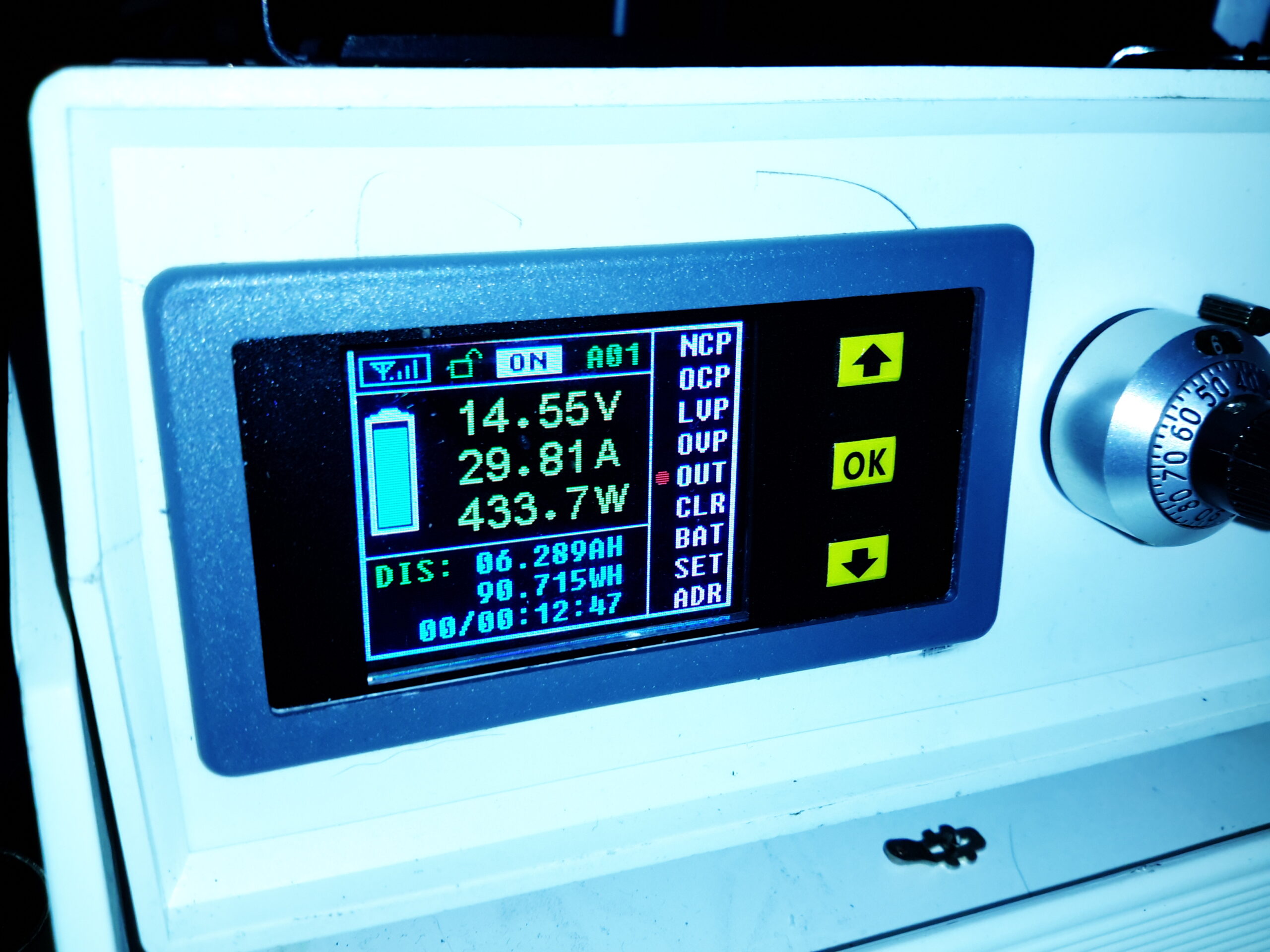
Load Test
Here’s the finished supply under a full load test – it’s charging a 200Ah deep cycle battery. The meter offers many protection modes, so I’ve set the current limit at 30A – preventing Sony’s built in over current protection on the PSU tripping with this function is a bonus, as the supply takes a good 90 seconds to recover afterwards. I’ll go into the many modes & features of this meter in another post.
This is another automotive part, this one was found lurking inside an LCD info display from a BMW. I didn’t manage to find a datasheet for this one, the neither the part number on the package or the wafer code on the die itself revealed anything.
As supplied, the RTL type tuner dongles are a little fragile, especially when they’ve got a rather heavy coax feeder attached for Ham Radio use.
The MCX antenna connectors on the tuner can’t stand up to much abuse, and even the USB plug rips itself from it’s mounts after a while with a heavy weight on the end. Since this dongle sits in my radio go bag, it definitely needed some protection & support.
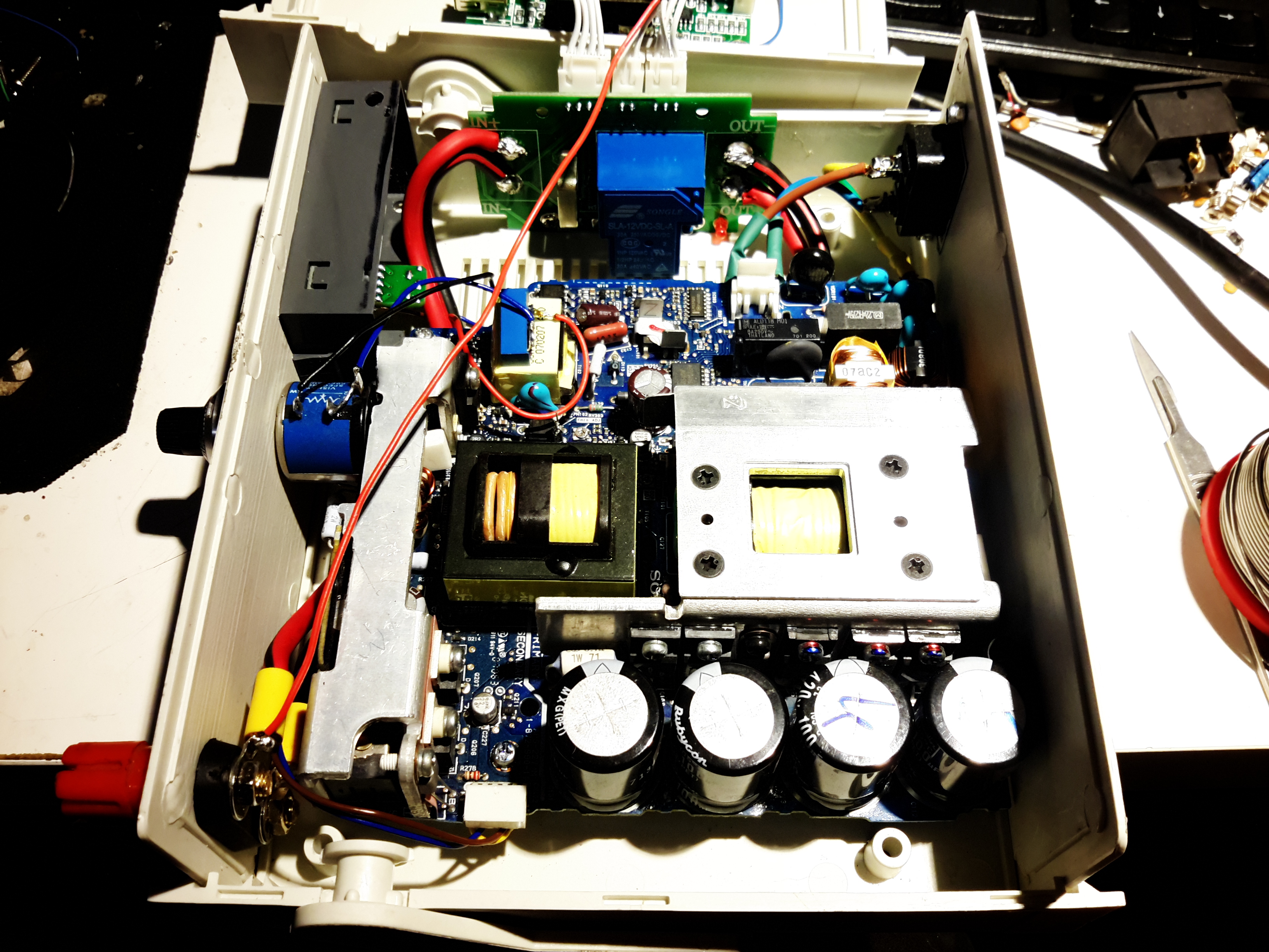
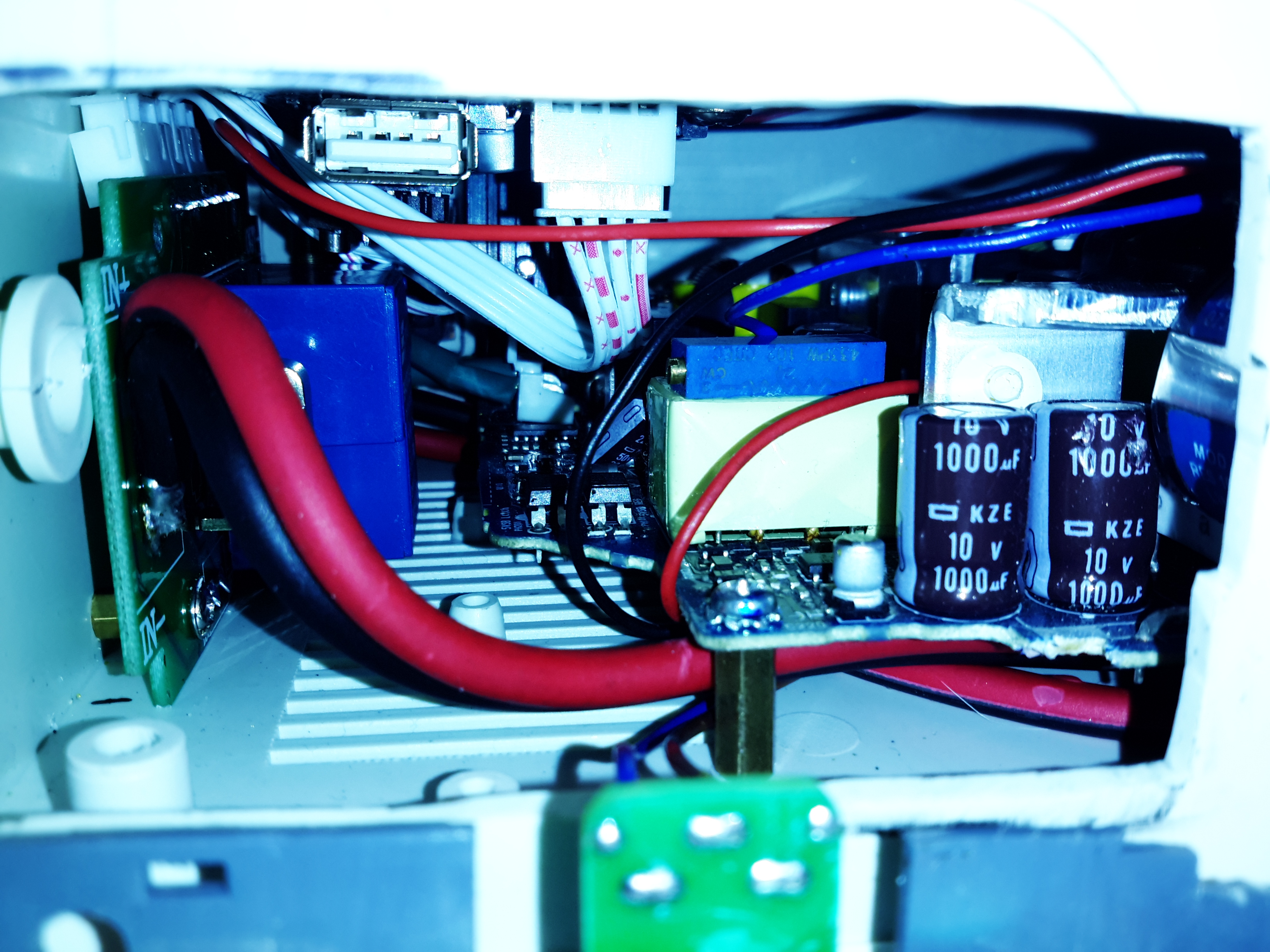
PCB
The PCB itself is removed from it’s flimsy plastic casing, the USB plug is desoldered from the board.
To the exposed pads, a USB cable is soldered, giving much more flexibility in where the tuner is placed.
Instead of using the MCX antenna connector on the PCB, the coax is stripped & soldered direct to the PCB itself, as this connector has become unreliable.
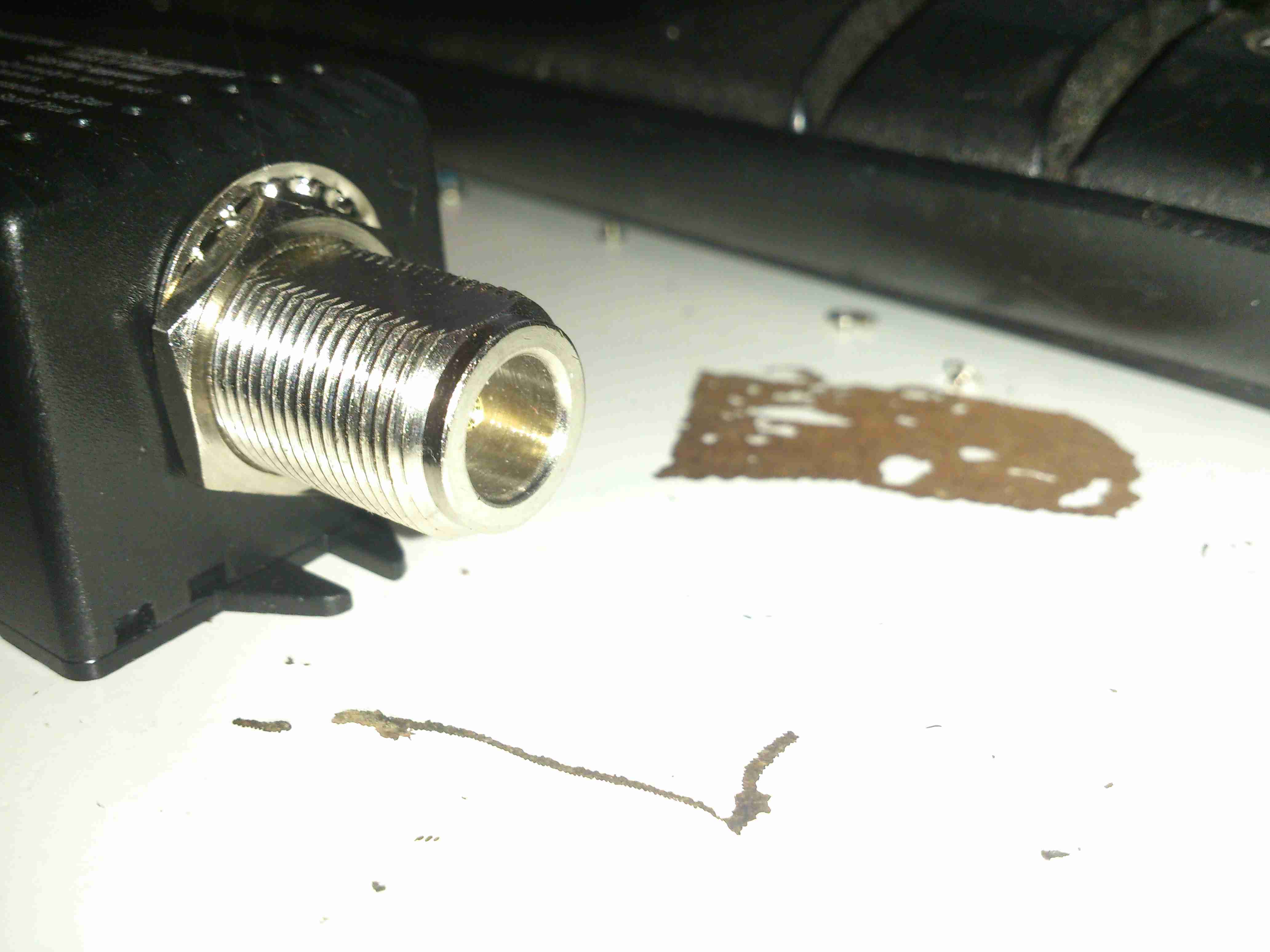
N-Connector
To get the RF into the device, the case is fitted with an N connector, as is everything else in my shack.
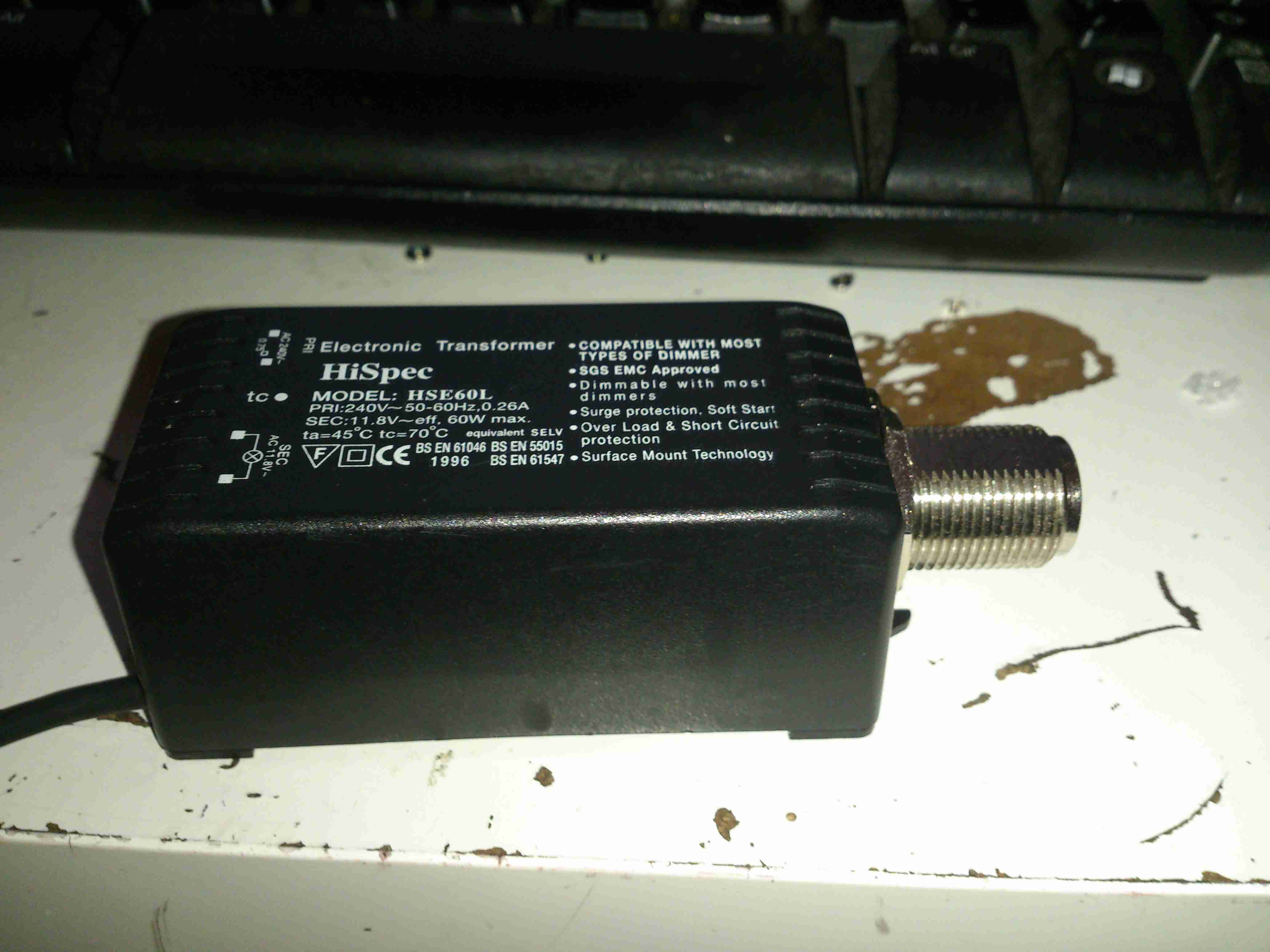
Boxed
The box used is a surplus one which previously housed an electronic lighting transformer. This would be very easy to waterproof as well, for more protection against outdoor use.
Now the controllers have arrived, I can rejig the supplies to have proper thermal control on their cooling.
Changes Overview
Here’s the top off the PSU. The board has been added to the back panel, getting it’s 12v supply from the cable that originally fed the fan directly. Luckily there was just enough length on the temperature probe to fit it to the output rectifier heatsink without modification.
To connect to the standard 4-pin headers on the controller, I’ve spliced on a PC fan extension cable, as these fans spent their previous lives in servers, with odd custom connectors.
Fan Controller
Here’s the controller itself, the temperature probe is inserted between the main transformer & the rectifier heatsink.
I’ve set the controller to start accelerating the fan at 50°C, with full speed at 70°C.
Full Load Test
Under a full load test for 1 hour, the fan didn’t even speed up past about 40% of full power. The very high airflow from these fans is doing an excellent job of keeping the supply cool. Previously the entire case was very hot to the touch, now everything is cool & just a hint of warm air exits the vents. As the fan never runs at full speed, the noise isn’t too deafening, and immediately spools back down to minimum power when the load is removed.
While I’m waiting for the fan controllers to arrive for the new cooling fans, I figured I’d get them fitted into the cases of the supplies & just have them run at minimum speed for now.
Fan Fitted
After removing the original small fan, I cut a larger square hole in the panel to fit the 60mm version. These fans only fit with some minor adjustment to the top & bottom mouldings, but the look isn’t too bad once the covers are back on. The wiring is routed through a small hole next to the fan itself.
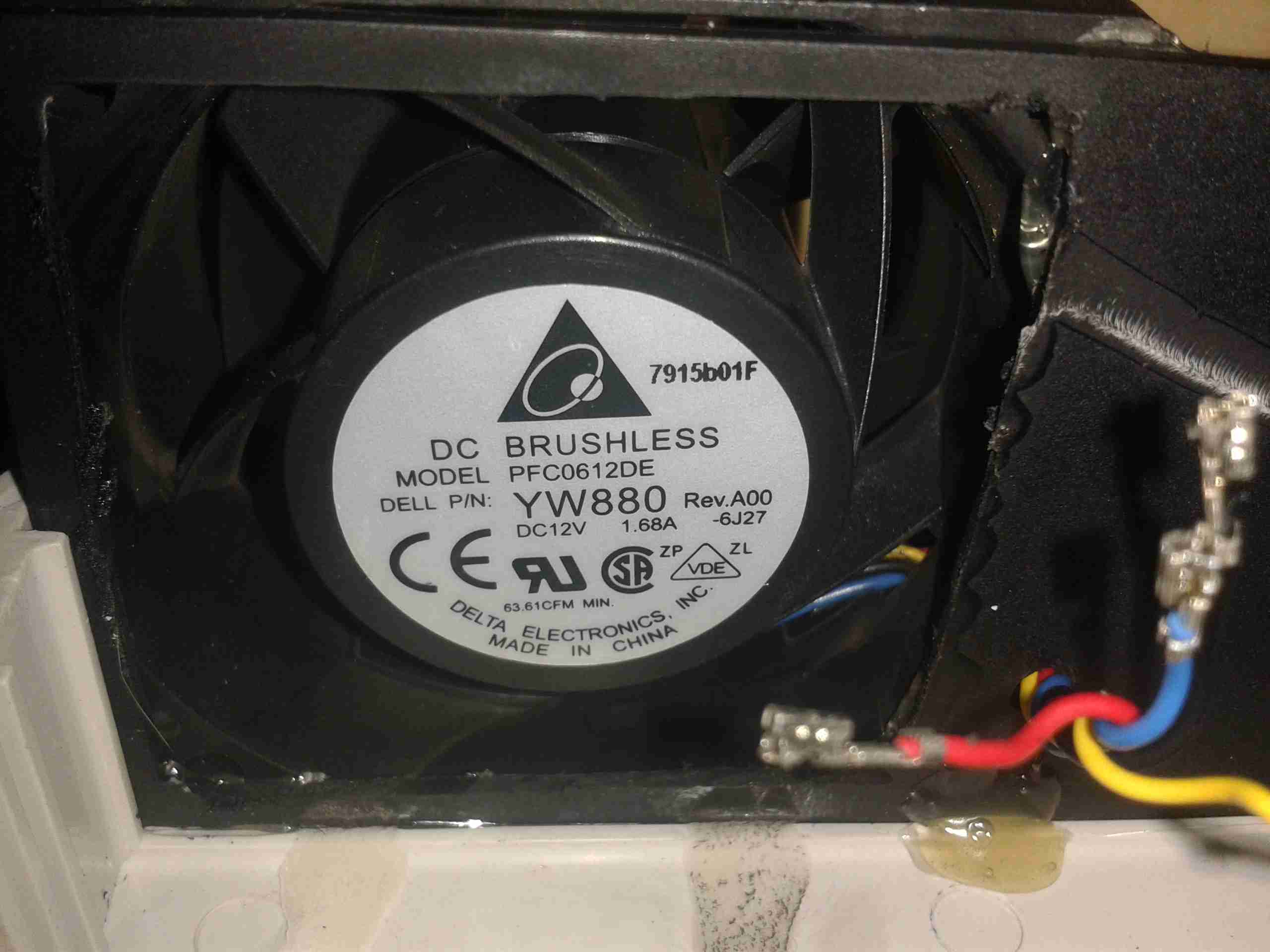
I’ve also upgraded on the fans again – these are PFC0612DE, with a higher airflow of ~70CFM at 12,000RPM.
To get the fans to run at minimum speed, the PWM control wire is connected directly to GND.
The power supplies I have recently built from surplus Cisco switch boards have started displaying a rather irritating problem – continual load of over 9A causes the supplies to shut down on overheat.
This was partially expected, as the original switches that these supplies came from are cooled by a monster of a centrifugal blower that could give a Dyson a run for it’s money. The problem with these fans is that they’re very loud, draw a lot of power (3-4A) and aren’t small enough to fit into the case I’ve used for the project.
The solution of course, is a bigger fan – I’ve got some Delta AFB0612EHE server fans, these are very powerful axial units, shifting 60CFM at 11,000RPM, with a power draw of 1.12A.
They’re 60mm diameter, so only just fit into the back of the case – although they stick out of the back by 40mm.
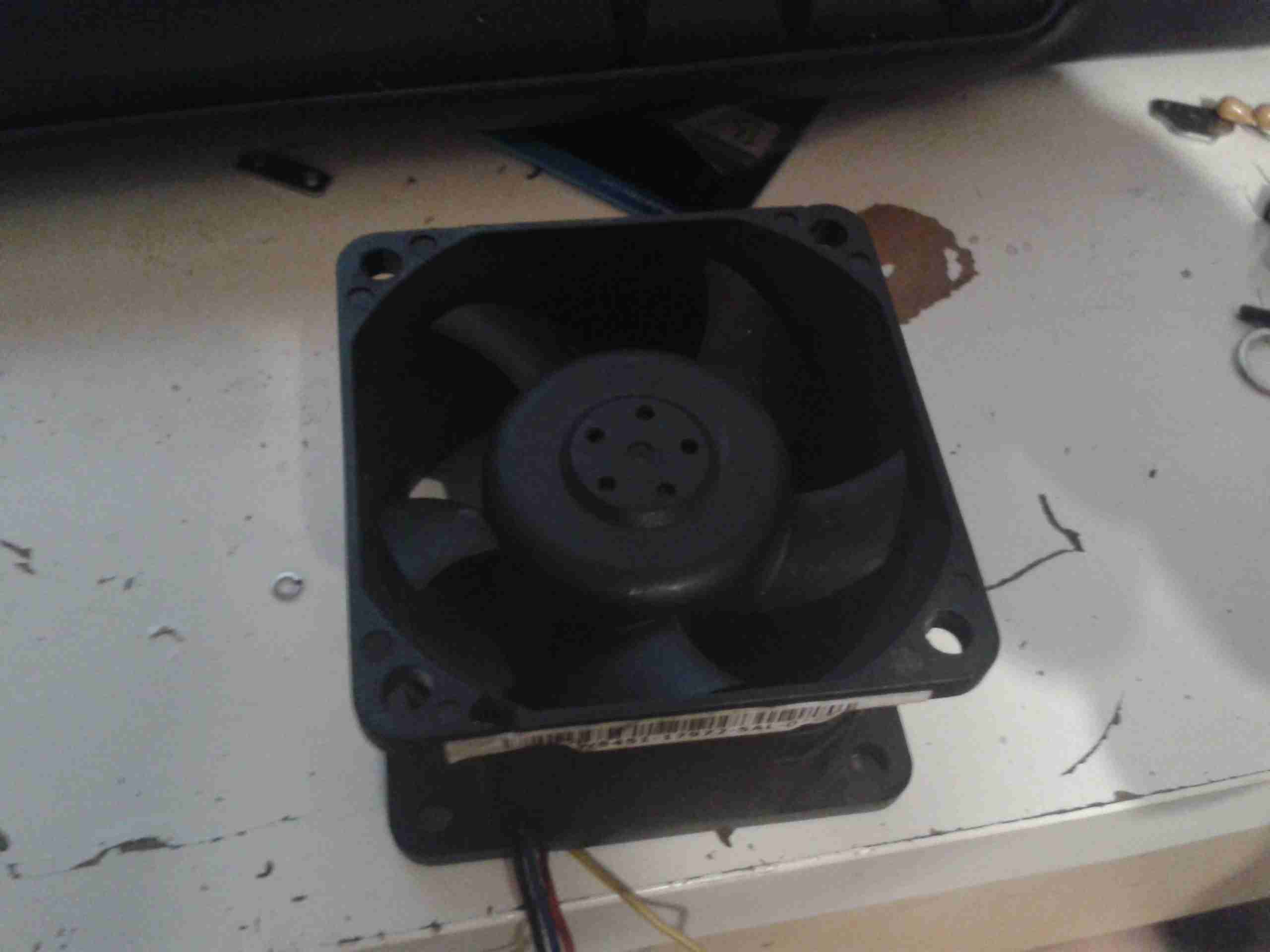
Monster Fan
Here’s the fan, not the beefiest I have, but the beefiest that will fit into the available space.
These will easily take fingers off if they get too close at full speed, so guards will definitely be required.
To reduce the noise (they sound like jet engines at full pelt), I have ordered some PWM controllers that have a temperature sensor onboard, so I can have the fan run at a speed proportional to the PSU temperature. I will probably attach the sensor to the output rectifier heatsink, since that’s got the highest thermal load for it’s size.
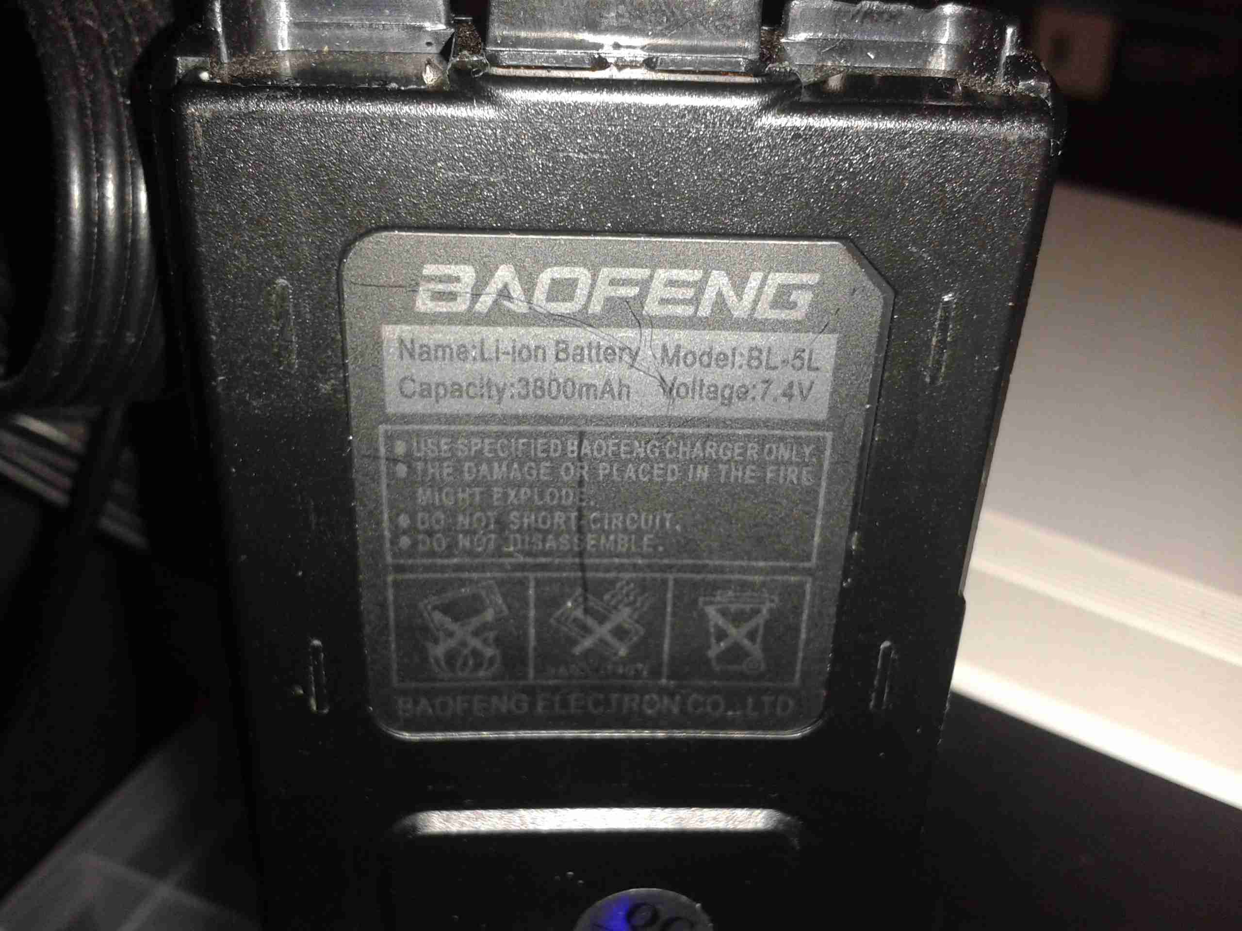
I’ve had a couple of larger batteries for my UV-5Rs for some time now, and decided to do a quick teardown to see if they’re actually the capacity claimed.
BL-5L Battery
Here’s the label, claiming 3800mAh (3.8Ah) of battery capacity.
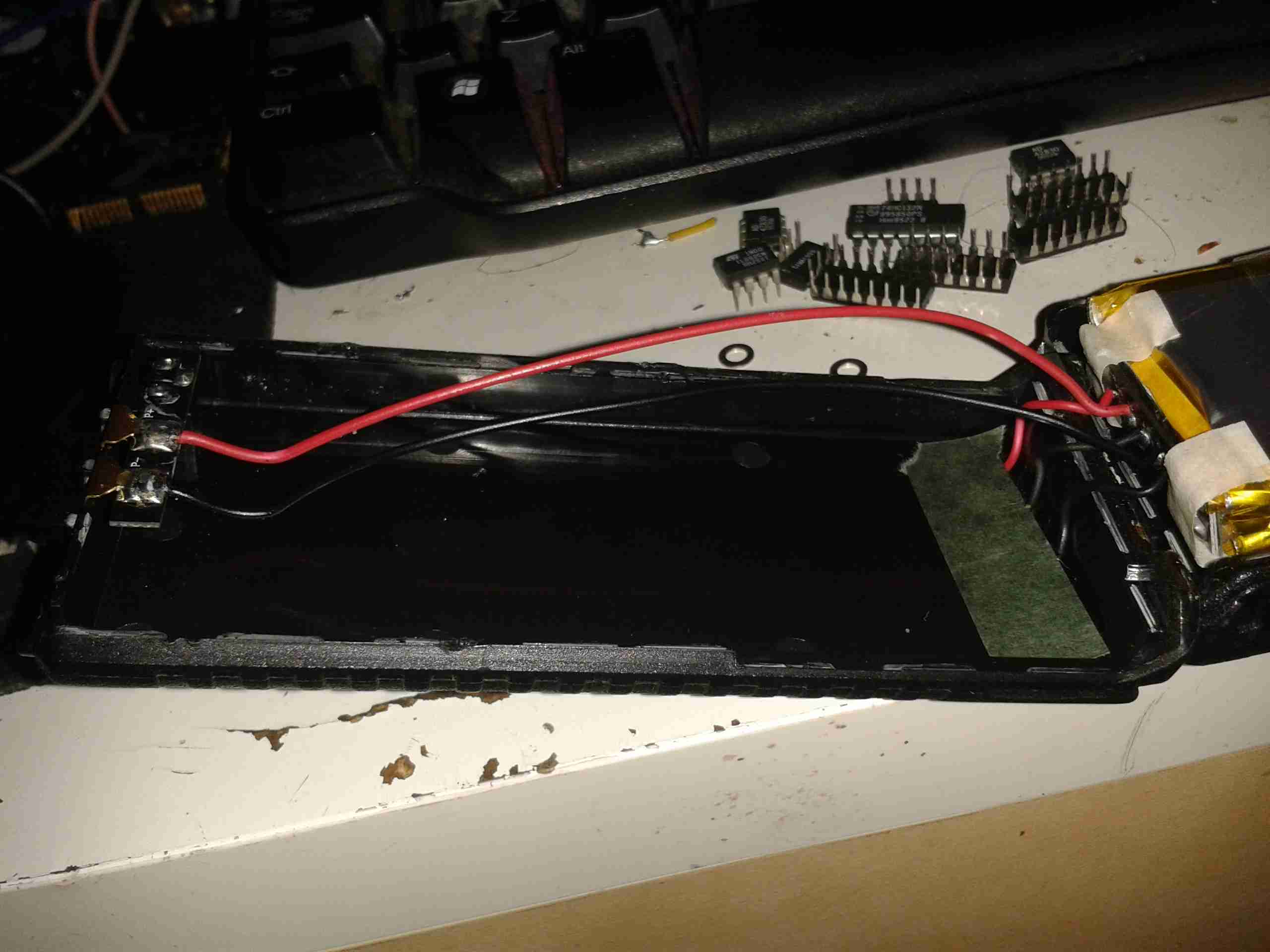
These batteries are held together with glue, but a good way to get these kinds of things open is by whacking the seams with the handle of a screwdriver. This cracks the glue without damaging the casing.
Battery Cracked Open
After a few minutes of cracking the seams, the battery comes right open. The pair of wires link the protection board on the cells to the DC terminals on the top of the pack. The charging terminals are under the cardboard insulator on the right.
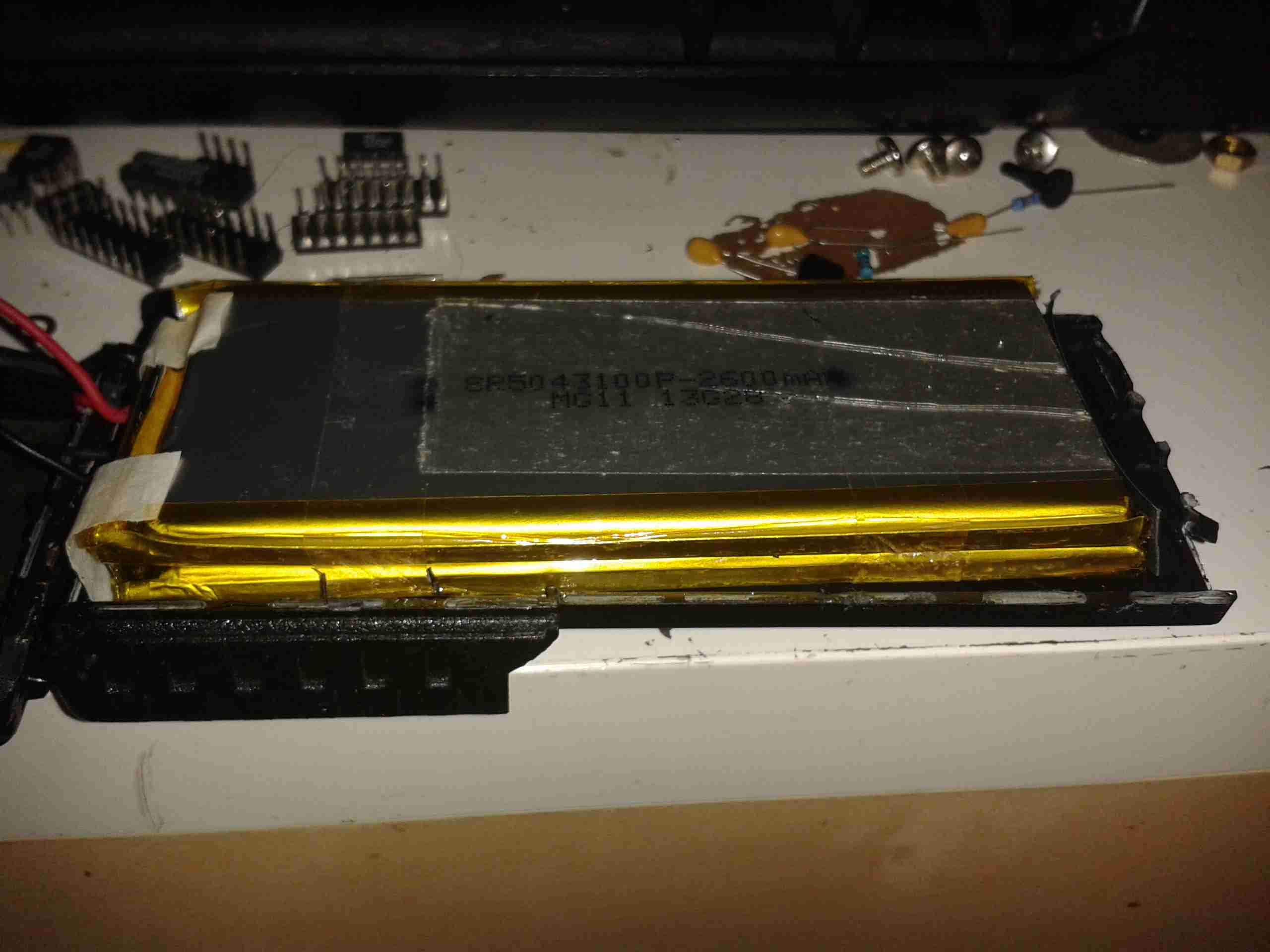
Cells
Here’s the other half of the case, with the cells themselves. These are wired in series for a 7.2v pack, and at a capacity of 2600mAh (2.6Ah) printed on them, the label clearly lies about the capacity.
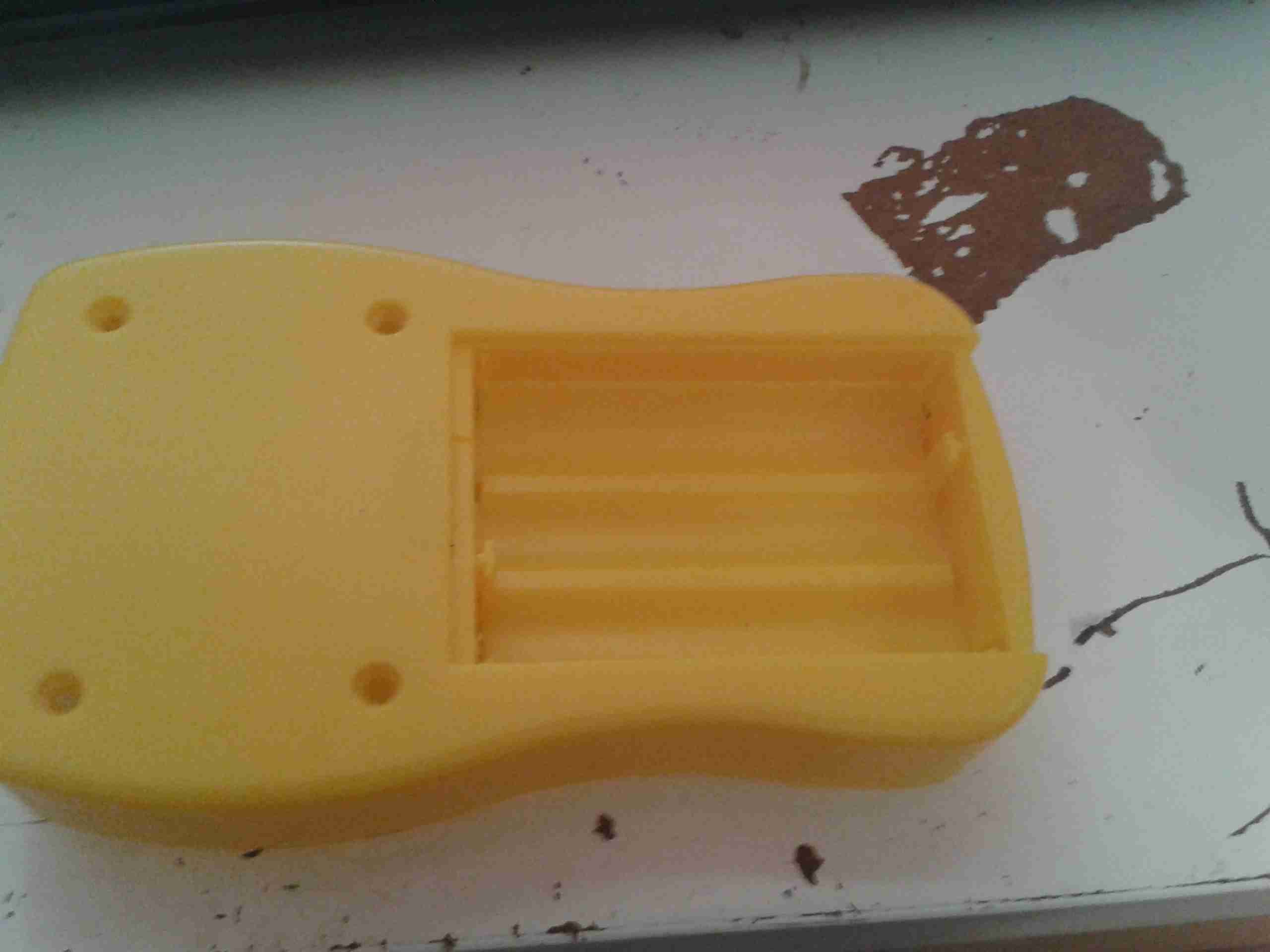
From the factory, the GY561 meter uses alkaline AAA cells for power. As these are not rechargable, and I don’t carry any other devices that take such batteries, I figured I’d replace them with a single Lithium Polymer cell that I can charge via USB.
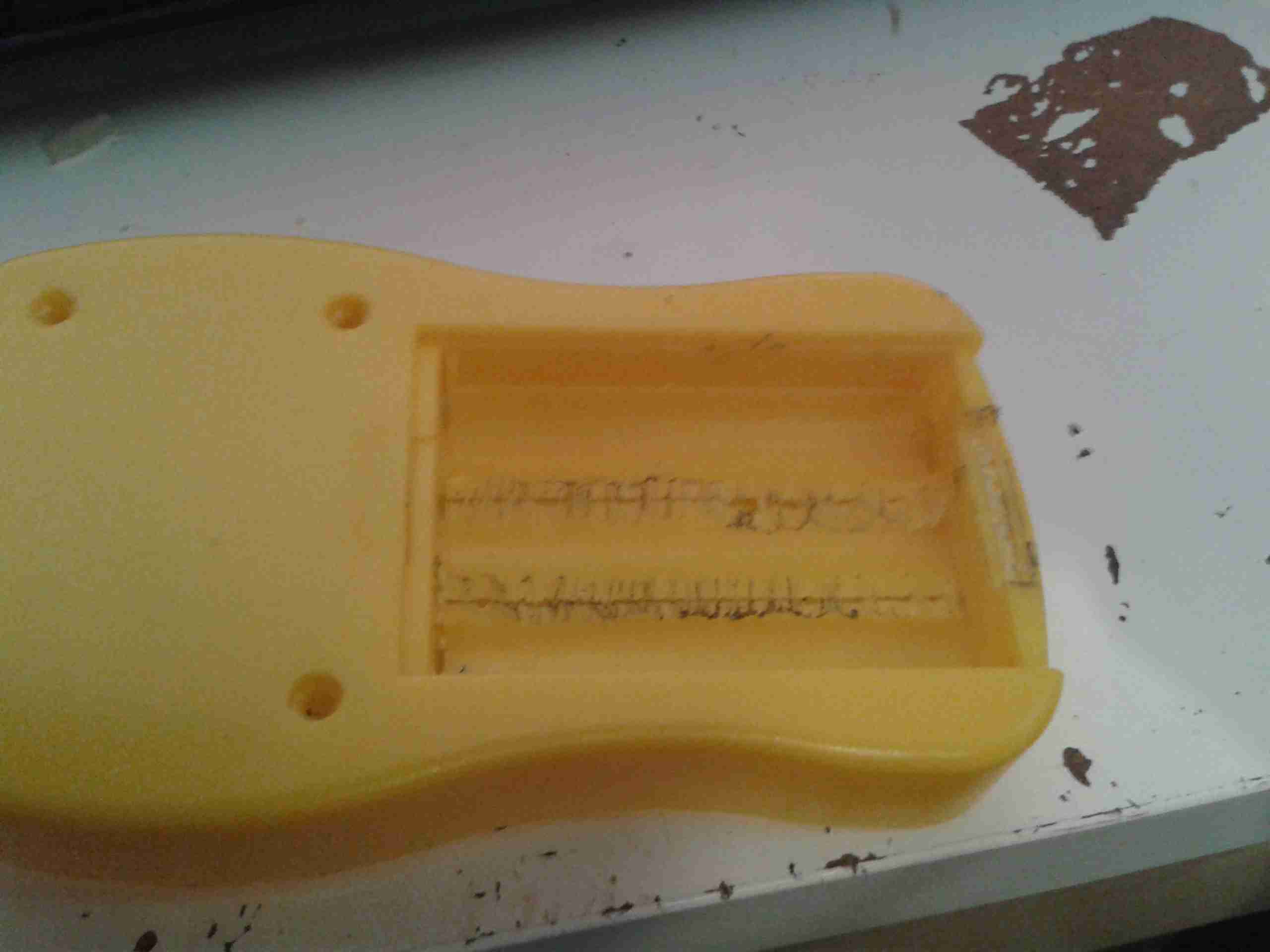
Battery Compartment
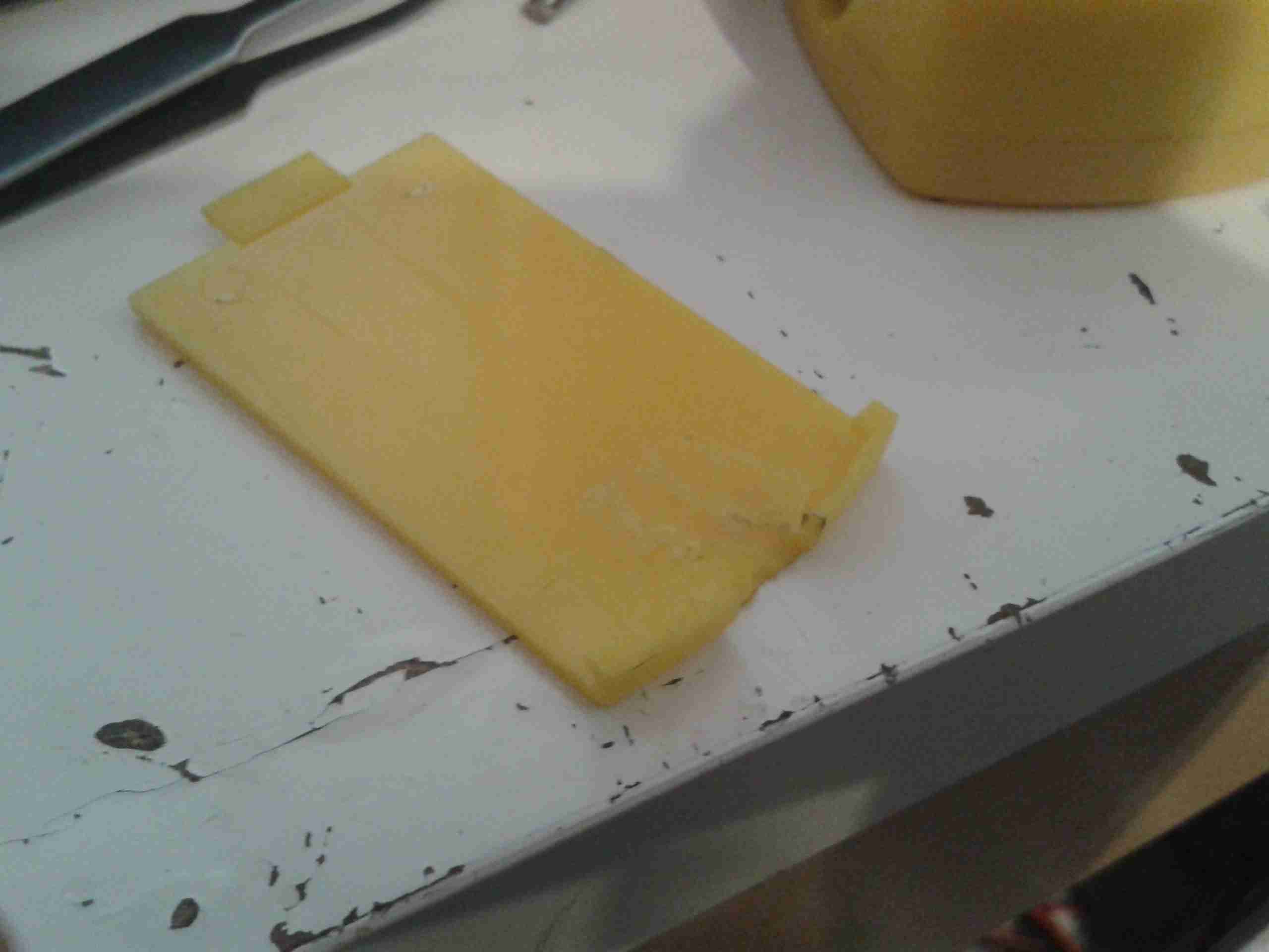
Here’s the battery compartment, with the original spring terminals removed.
I searched eBay for a suitable sized cell, and settled on a 1000mAh type, with dimensions of 47mm x 28mm x 7mm.
This size cell required a small amount of modification to the battery compartment to make it fit properly with the associated charge & protection circuitry.
Modified Compartment
Here’s the modifications made to the compartment, I’ve ground away the plastic to make the bottom flat, and the plastic tabs that retained the original spring terminals.
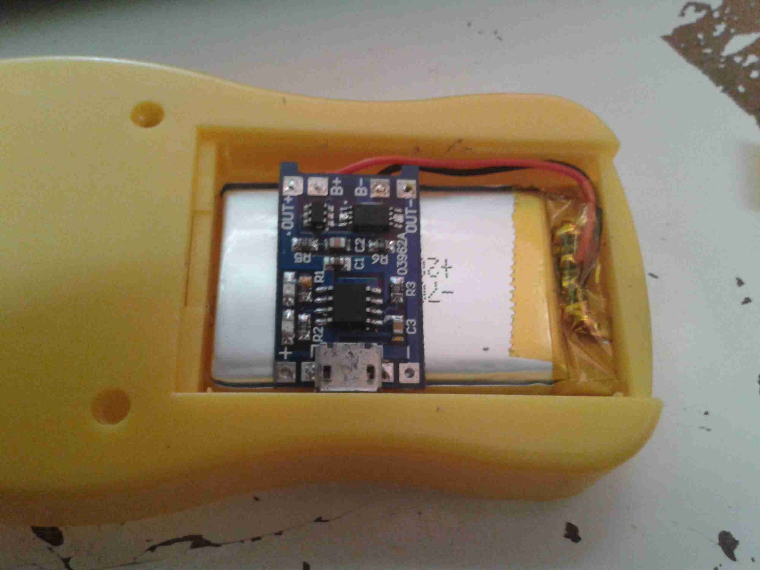
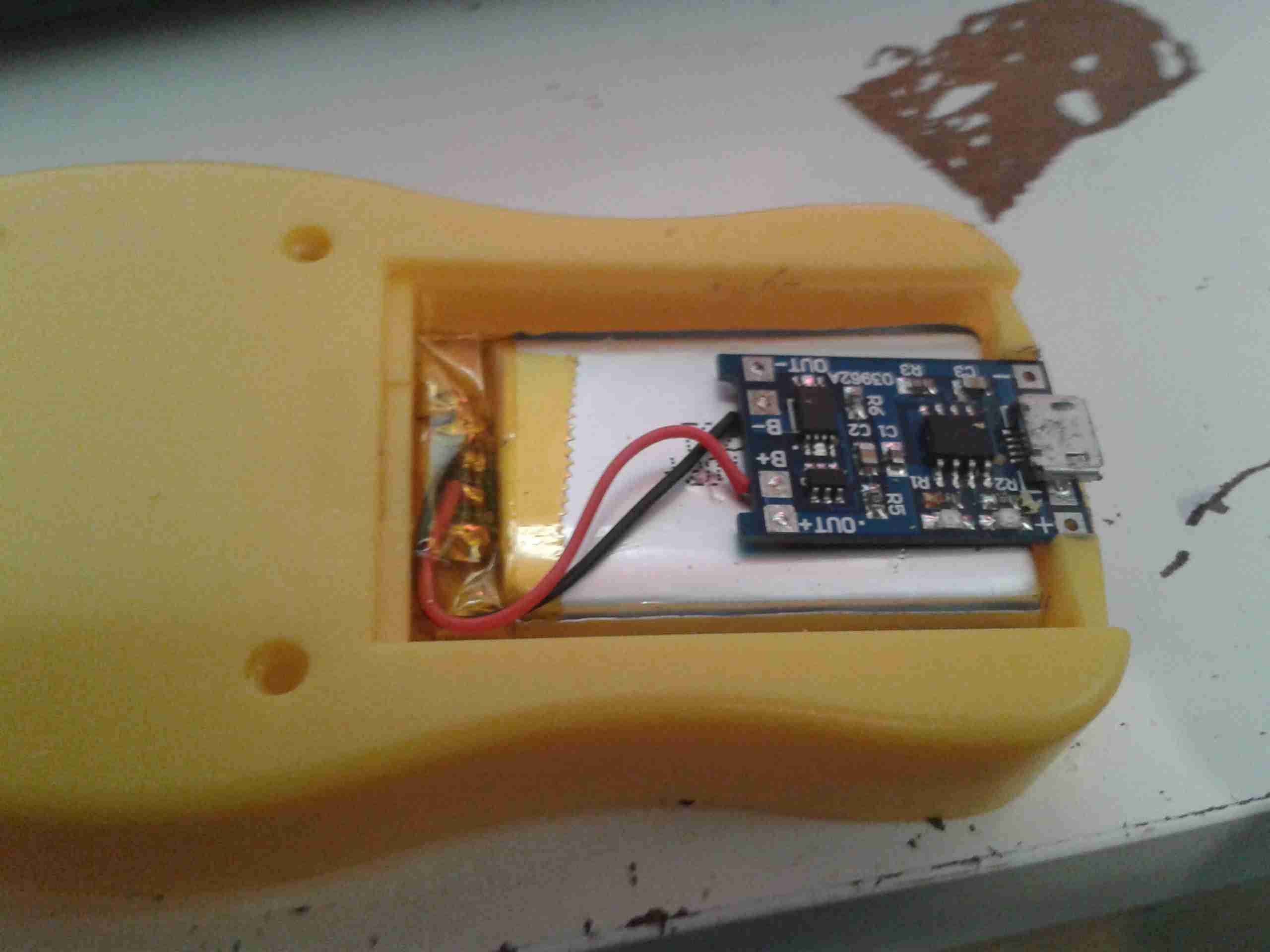
Modifications
After grinding away the original battery spring holders with a dremel, the cell fits perfectly in the available space. The small PCB on the top of the cell is the USB charger & protection.
Charger
The charger is located in a slot cut in the bottom of the casing, so the USB port is accessible from outside the compartment.
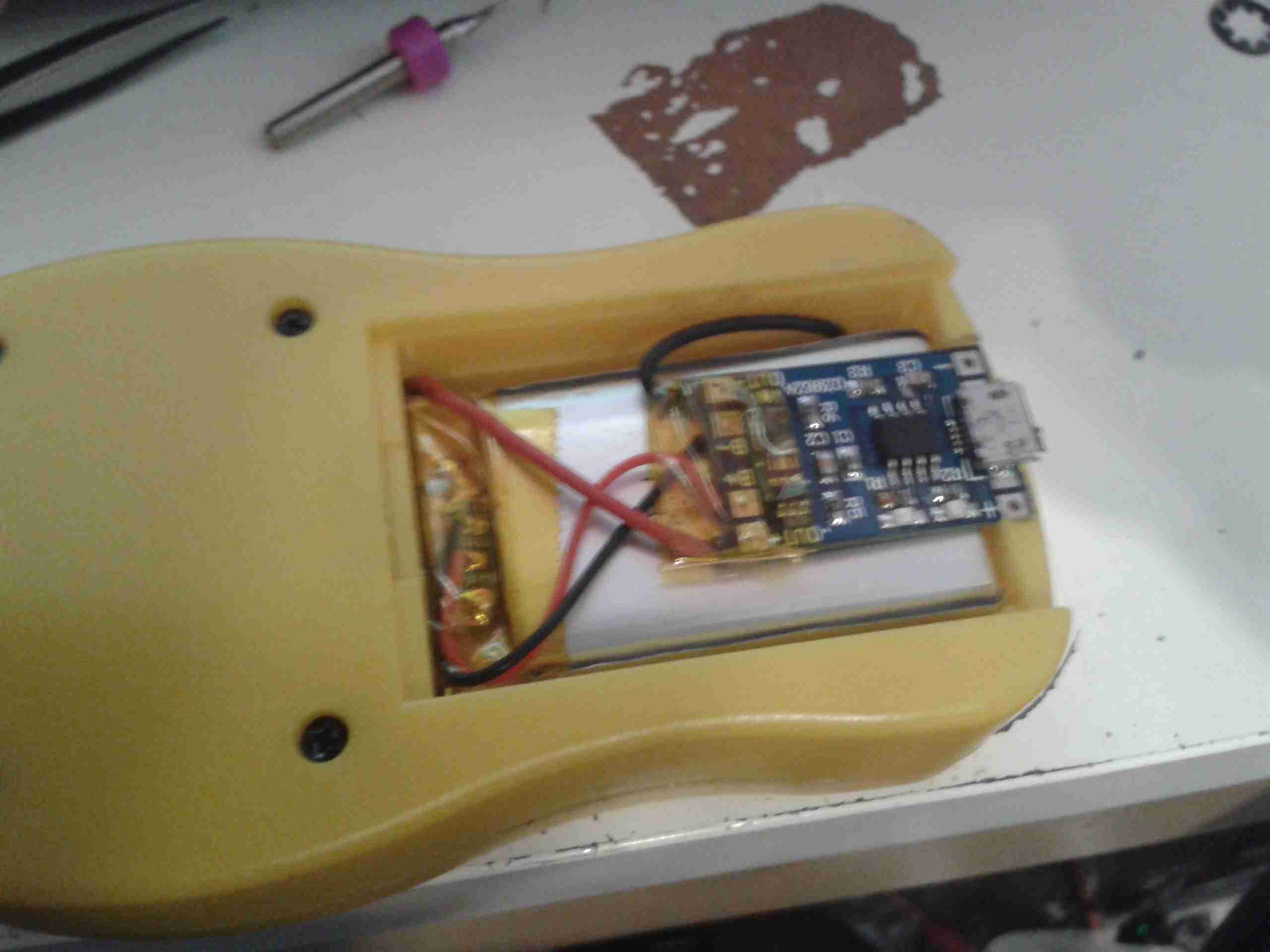
Wiring
Here’s the rest of the wiring completed, with the power wires going through holes in the bottom of the battery compartment to join onto the PCB where the original terminals were located. I have insulated the solder joints on the control PCB with some Kapton tape to prevent any shorts against the lithium cell.
Battery Cover
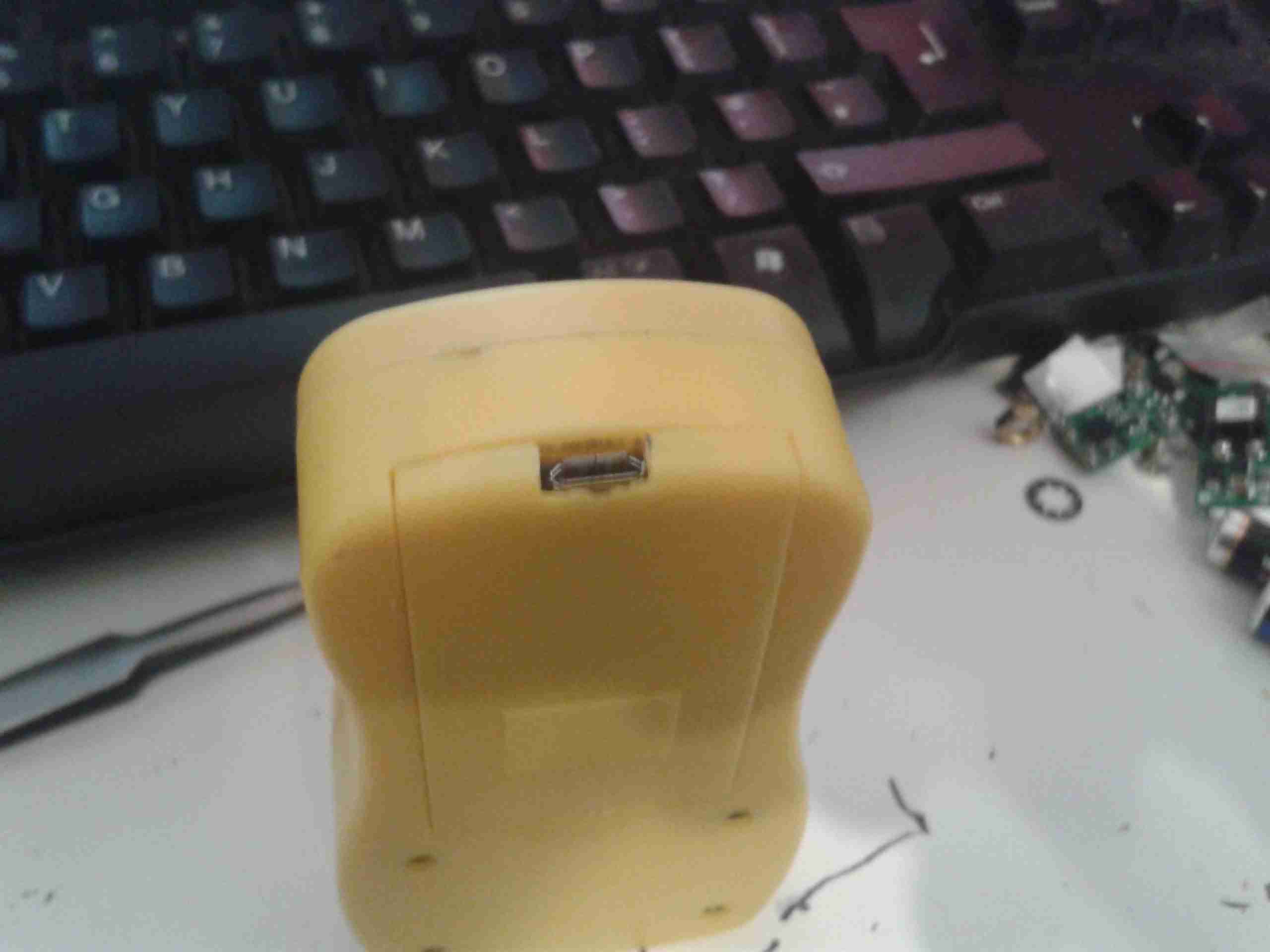
A small cutout was also required in the battery cover to allow the USB connector to poke out. This was easy to do on the soft plastic with a Dremel tool.
Charging Port
With the battery cover installed, the USB port is nicely recessed into the edge.
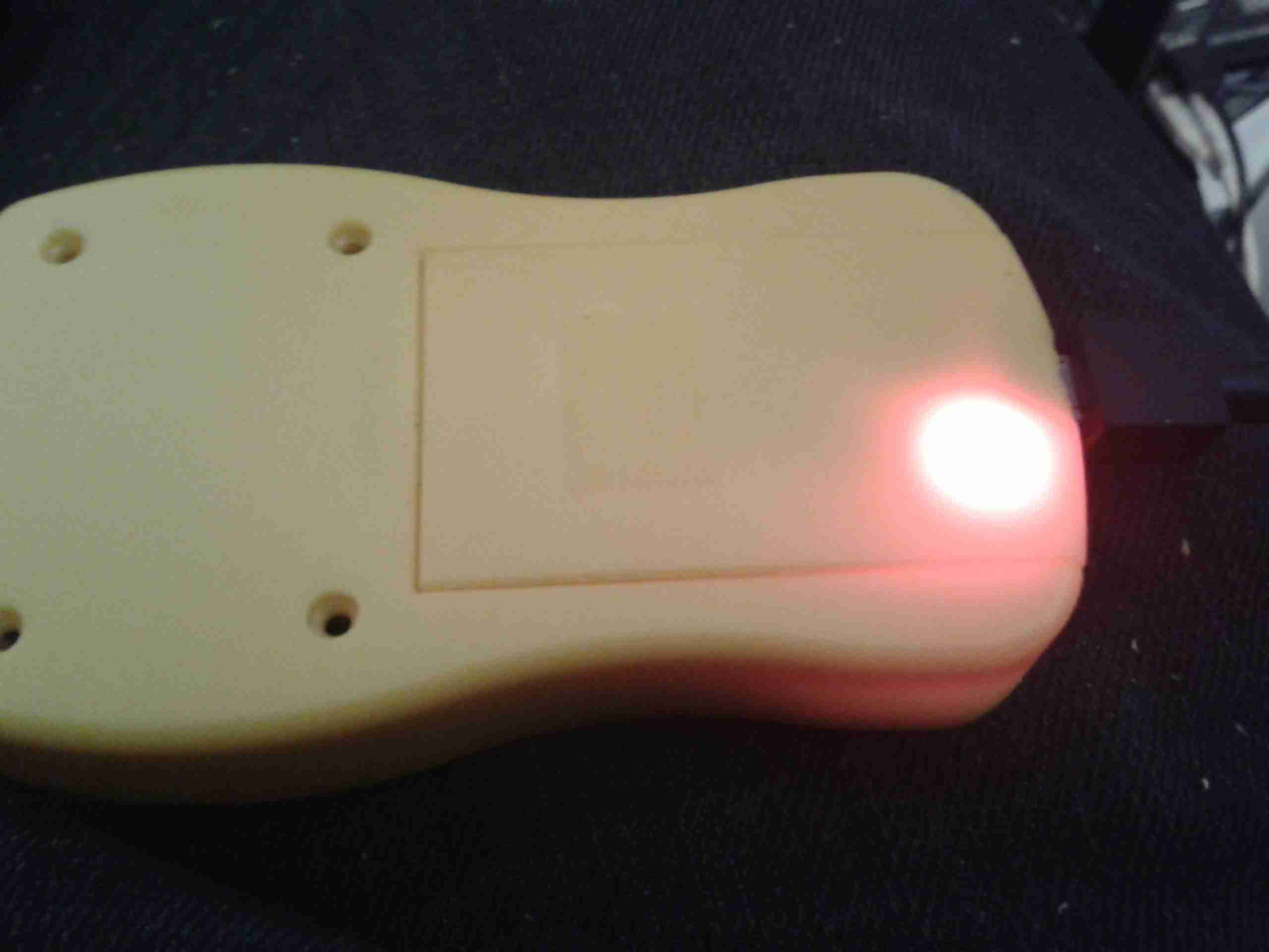
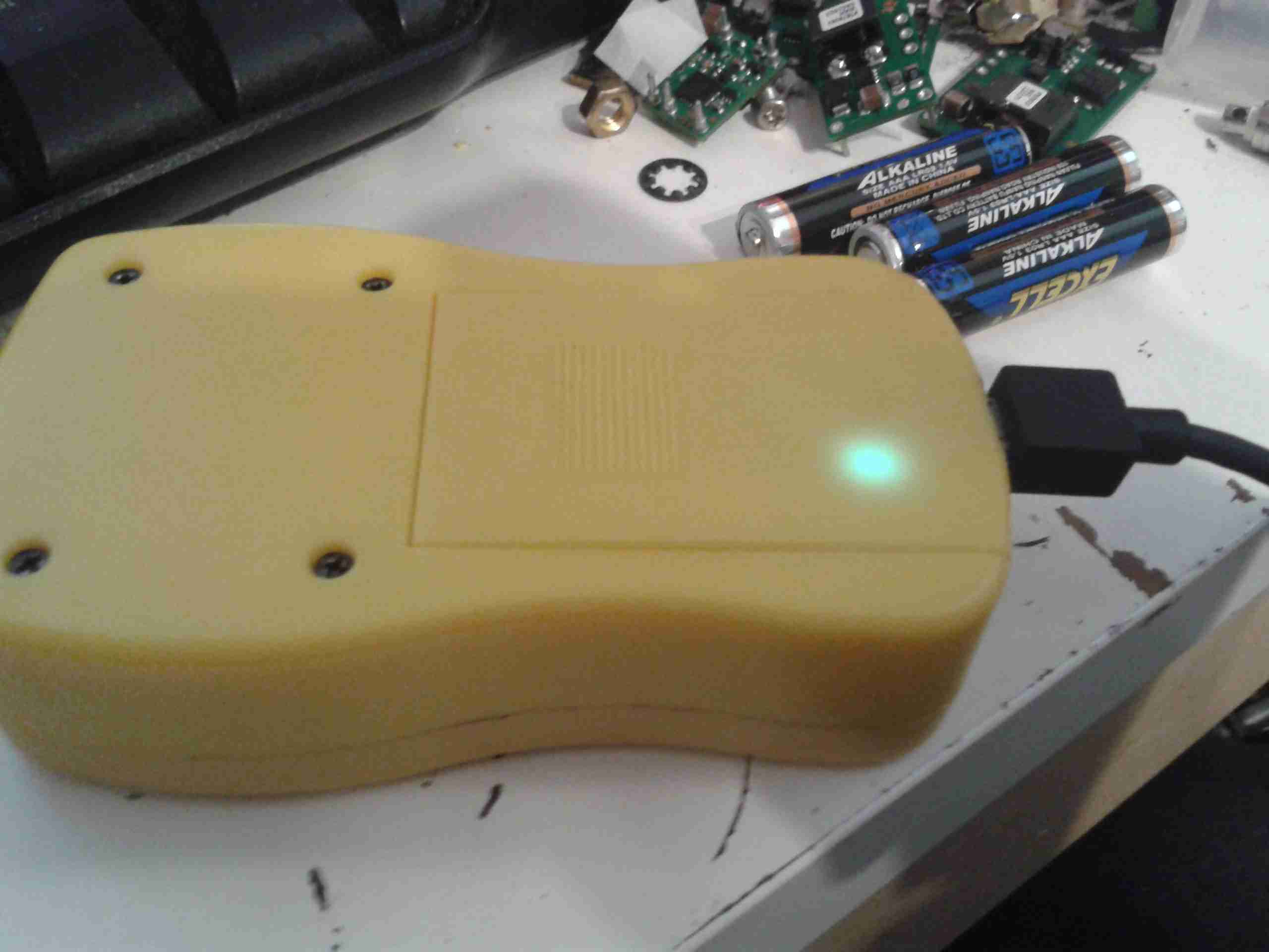
Charging LED
The indicator LEDs on the charging & control board show nicely through the plastic, here’s the unit on charge. When the charge is complete, another LED lights as shown below.
I really like the UV-82s, over the UV-5Rs I was originally using, so I’ve bought another pair. Here are the power levels on test. Tests were done with a full battery charge on the 2m/70cm calling frequencies.
Now this is amusing, captured tonight on GB3MR, the usual unlicenced plonker is now threatening us all on the air with the Police – not sure where he’s getting a criminal offence out of the fact that everyone on the repeaters is moving around to avoid him, but still. Nor is it an offence to share audio of Amateur Radio transmissions – they’re considered public domain.
Here’s the audio for your listening pleasure.
Here’s the final bit of the radio install now the required parts have arrived!
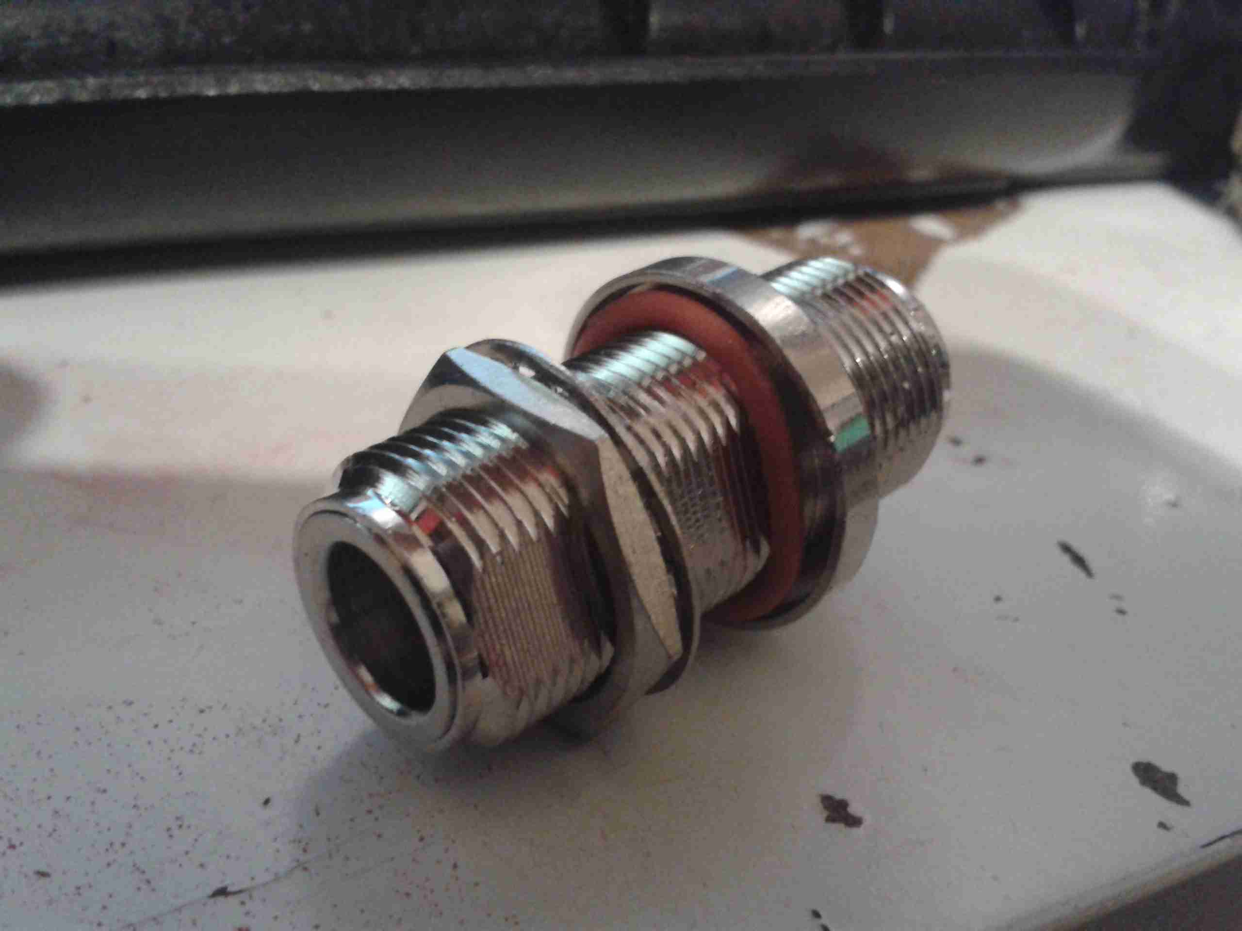
The radio being inside, we needed a reliable way to route the antenna coax through the hull to the external antenna, I managed to find some N-type bulkhead connectors, that are perfect for this job:
Bulkhead Fitting
This fitting will allow for simple disconnection of the antenna for service, and N-type connectors are water resistant.
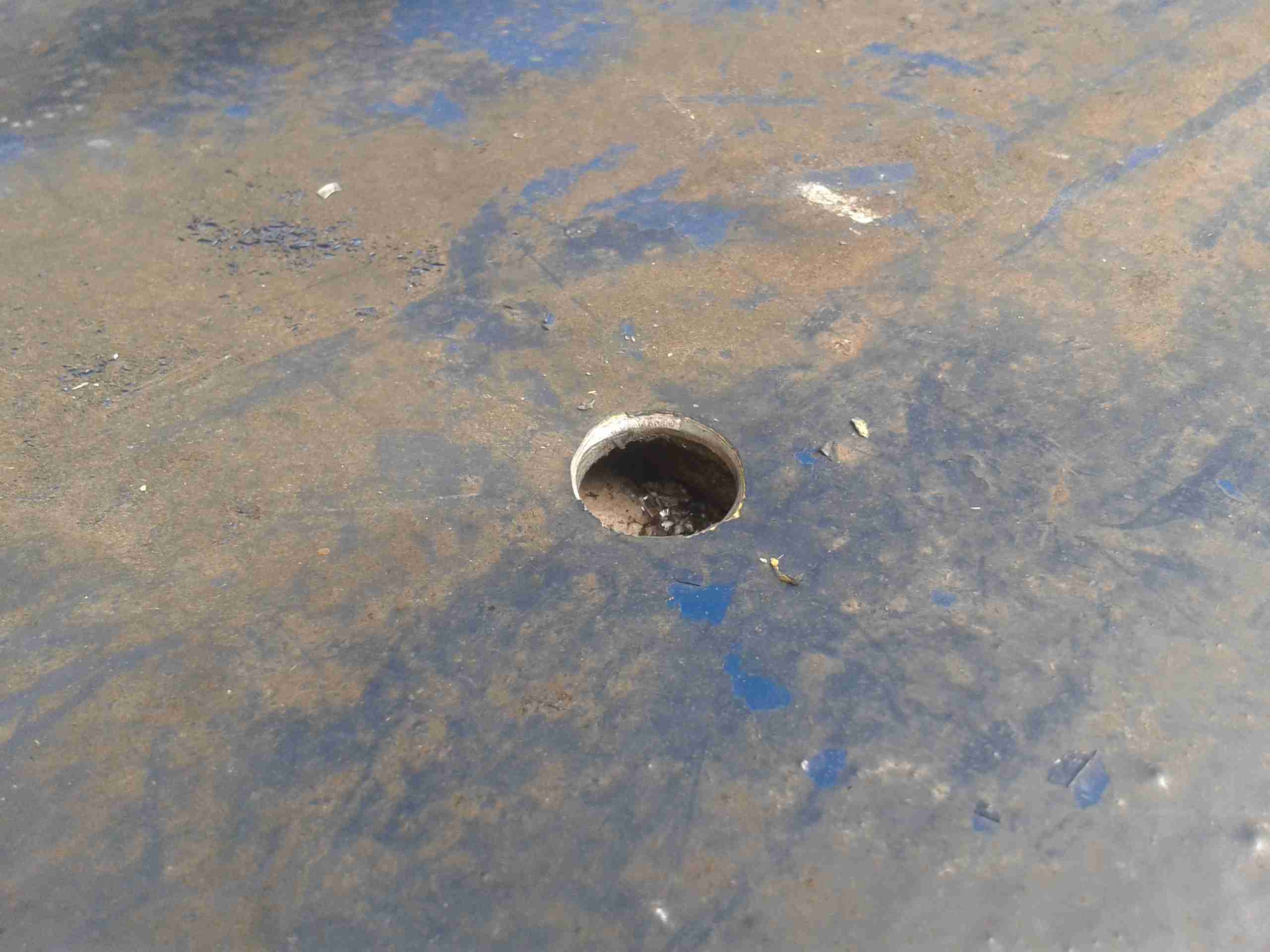
Hole
A hole was drilled in a suitable location with a cone drill. The steel here is pretty heavy, at 5mm. A spot between the handrail & the sliding roof was picked since there’s less chance of the fitting being knocked by any flying ropes, windlasses or crew members 😉
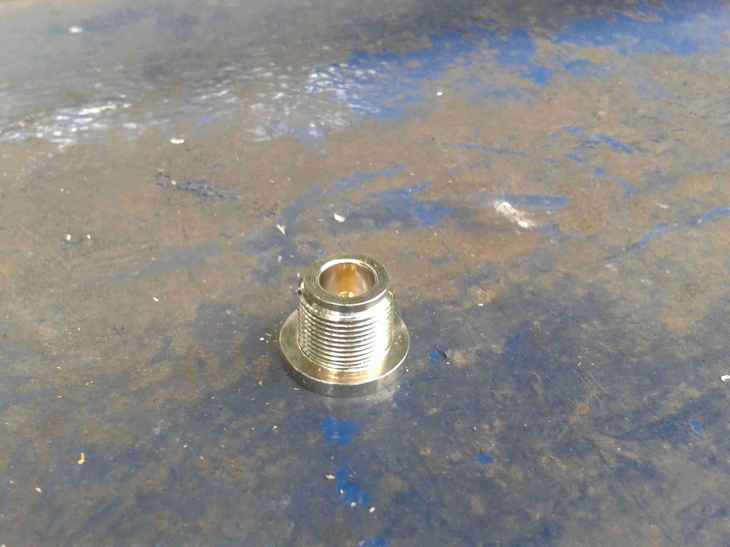
Bulkhead Connector
Here’s the connector fitted into it’s hole. The O-ring under the flange seals against the steel hull to prevent water getting through to the radio equipment on the other side.
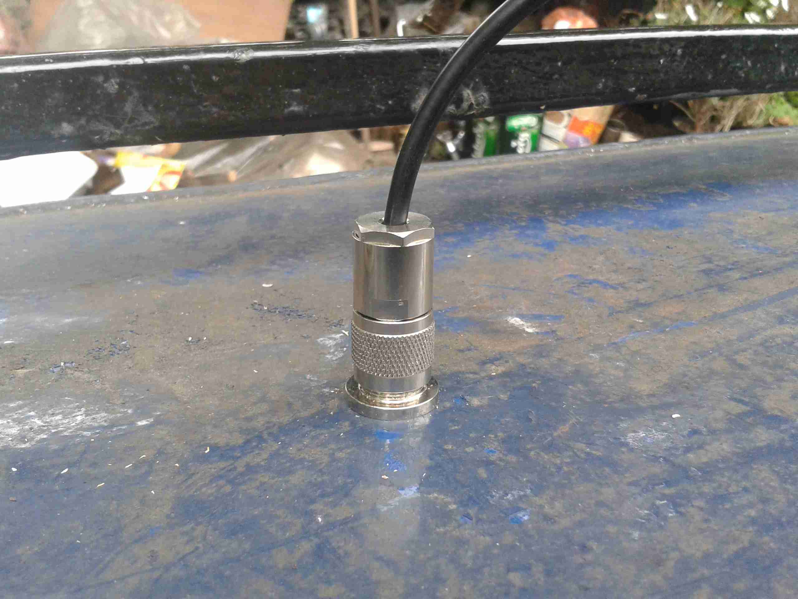
Completed
Completed connection to the antenna. The short run to the radio underneath (~18″) is RG213, but I’ve used RG-58 on the antenna itself since it’s more flexible. The antenna is only a metre or so away so losses shouldn’t be much of an issue.
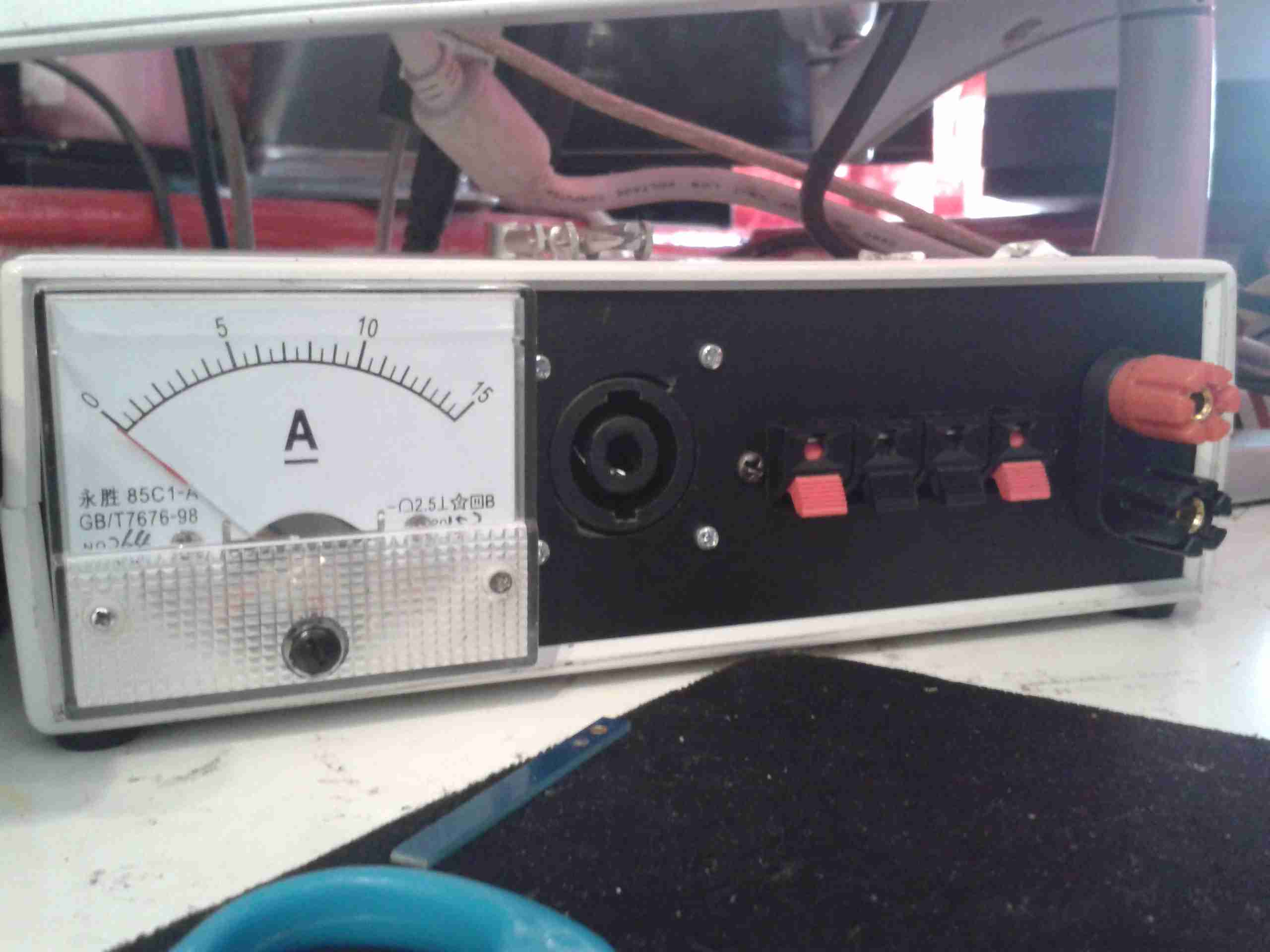
Following on from my recent power supply build, I’ve added on a couple of improvements:
Front Panel
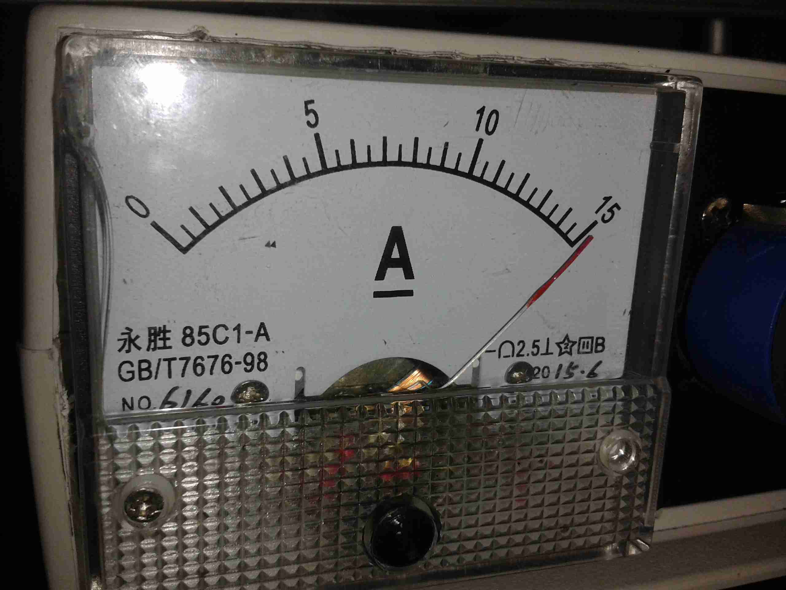
I’ve added on my standard SpeakOn type 30A connector, a bank of push terminals for quick connecting test leads, and a 15A FSD ammeter.
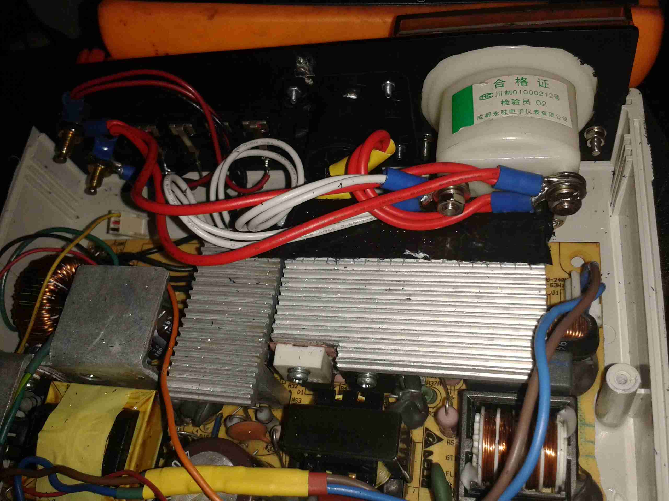
Panel Rear
Due to the limited space inside the supply, I’ve had to improvise some insulation on the mains-side heatsink to prevent a nasty accident. The heatsinks are tied to the supply’s HVDC bus negative, so they are energized at -145v DC relative to mains earth. This fact has given me a nasty surprise! The insulation is several layers of Kapton tape, with a couple of layers of Duct Tape. This along with trirated wire to the SpeakOn & the panel meter should ensure safety.
The Ammeter itself was sourced from eBay, for £2. It seems pretty accurate so far!
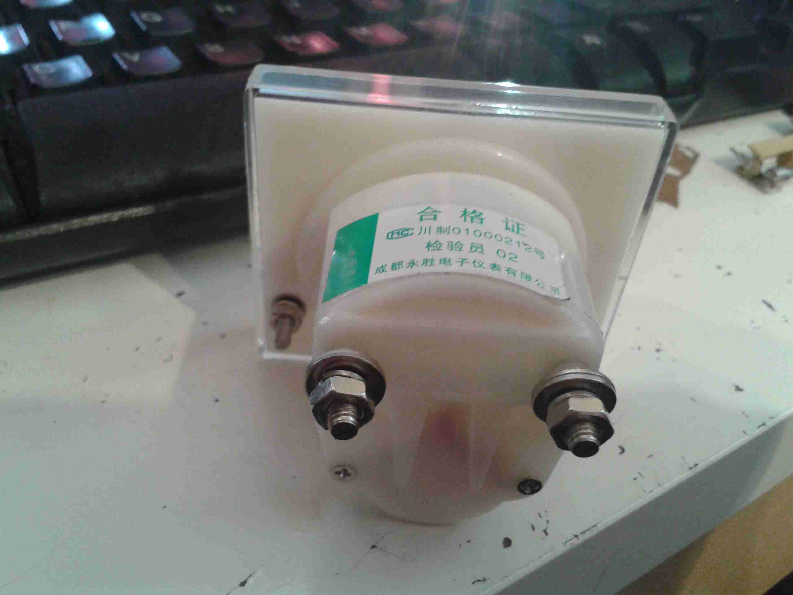
Ammeter
The shunt is built into the rear of these meters, in an ultrasonically welded part of the case, so I can’t examine it. Hopefully it is indeed rated to 15A!
The only things left to make this supply complete are a mains power switch, and a fan speed control, as the fan I have used is a little noisy at full speed. It will be good to get the speed based from the internal temperature, so the fan only runs at full speed when the supply is under load.
Here goes the local unlicensed prat yet again on GB3MR. I was trying to have a QSO with another station on there, but due to his weak signal, and the pirate’s strong signal, it made it impossible. Here’s the audio 🙂
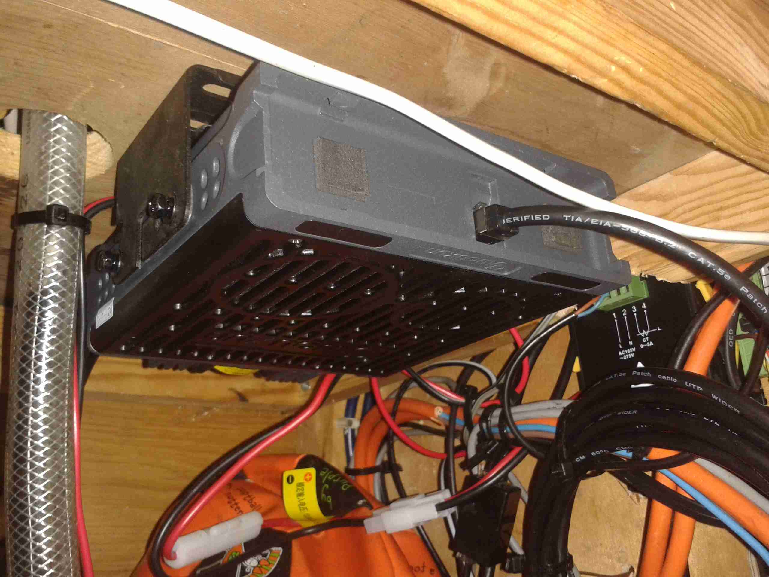
I often find myself carrying by go bag up to the boat during trips, so I can do some radio. However at 16lbs it’s a pain on public transport. A fixed radio was required! Another Wouxun GK-UV950P was ordered, and the fact that the head unit is detachable from this radio makes a clean install much easier.
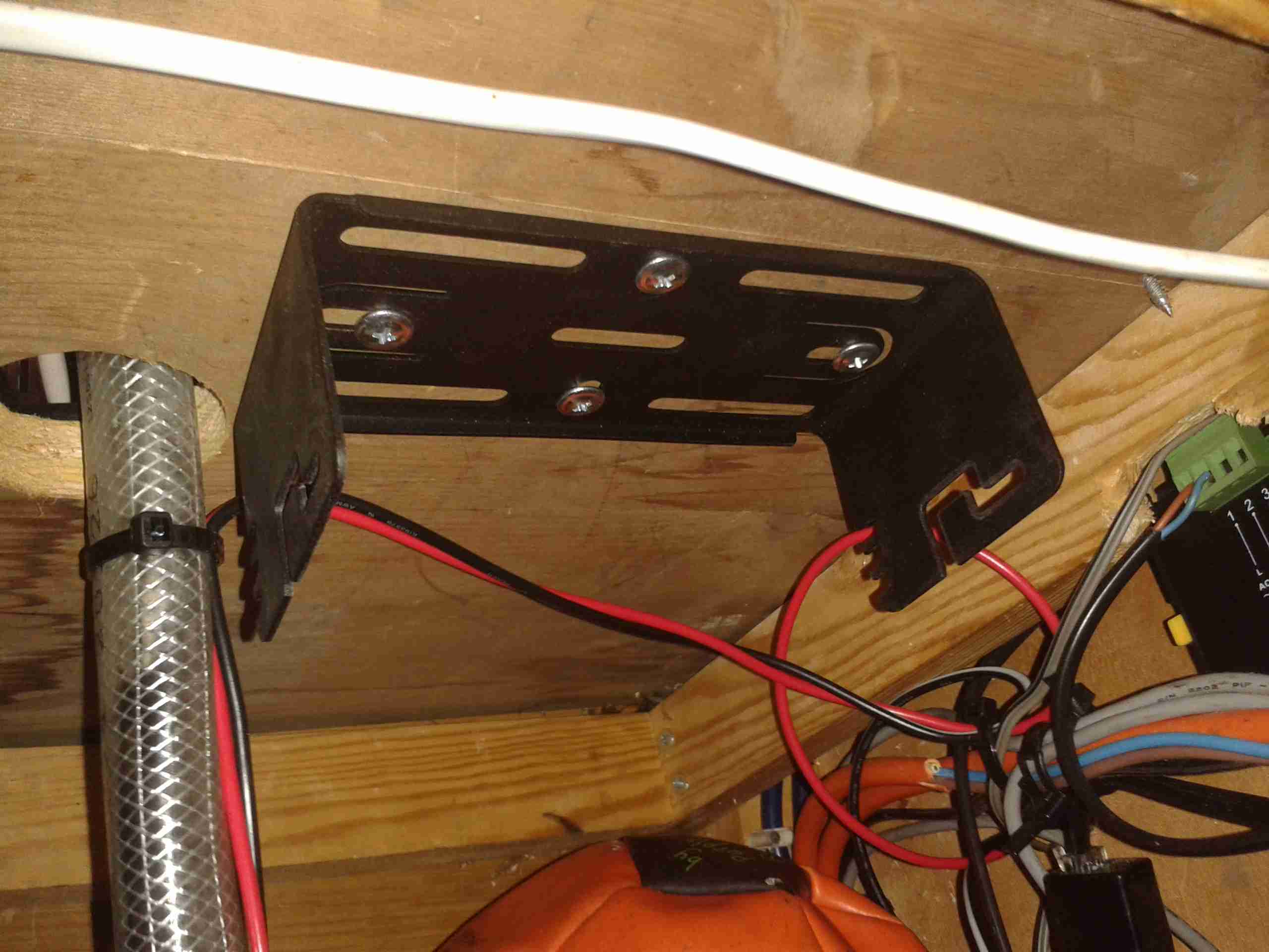
Mounting Bracket
I found a nice spot under a shelf for the main radio unit, above is the mounting bracket installed.
This location is pretty much directly behind where the head unit is placed, but the audio is a bit muffled by the wooden frame of the boat & some external speakers will be required for the future.
Main Radio Unit
Here’s the main radio unit mounted on it’s bracket, with the speakers facing down to improve the audio slightly. I used the supplied interface cable for the head unit, even though it’s too long. I do have the tools to swage on new RJ-45s, but the stuff is a pain to terminate nicely & I really just couldn’t be bothered. So it’s just coiled up with some ties to keep it tidy. Main power is provided directly from the main DC bus. (880Ah total battery capacity, plus 90A engine alternator, 40A solar capacity).
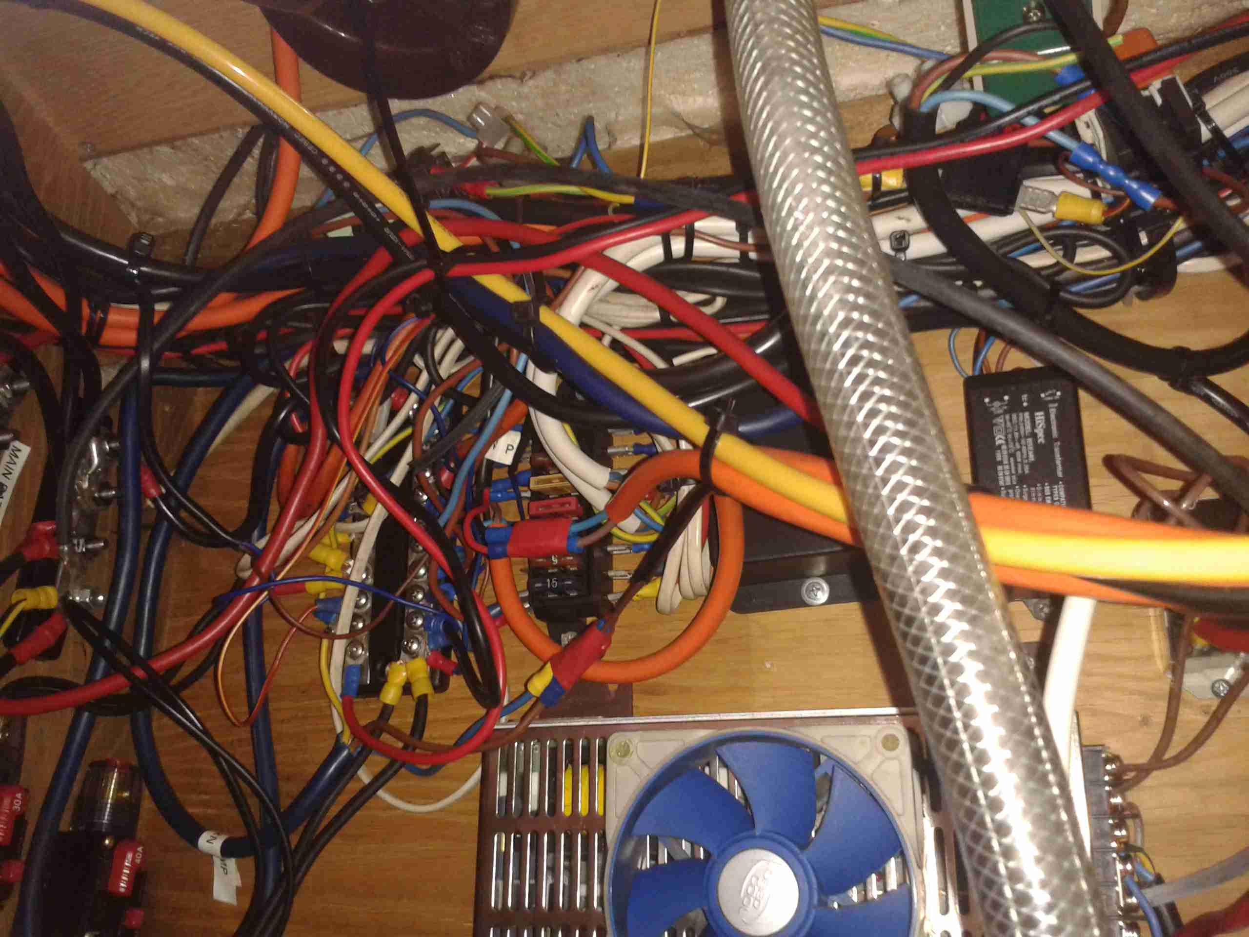
Rat’s Nest
Here’s the main DC bus, with the distribution bars. With the addition of new circuits over the years, this has become a little messy. At some point some labelling would be a good idea!
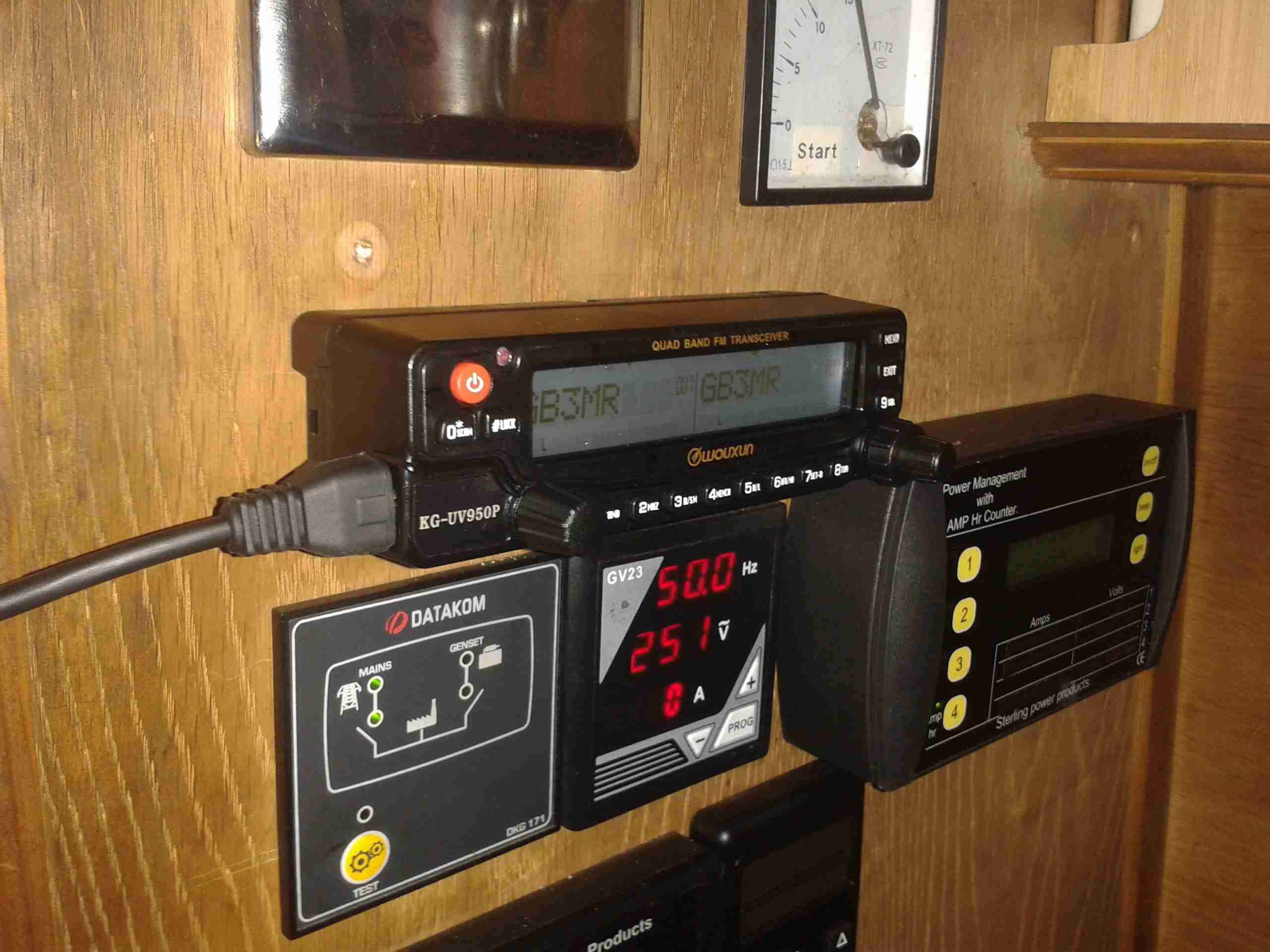
Radio Face Plate
Finally, the head unit is installed in a spot on the main panel. It does stick out a little more than I’d like, but it’s a lot of very dusty work with the router to make a nice hole to sink it further in. All my local repeaters & 2m/70cm simplex are programmed in at the moment.
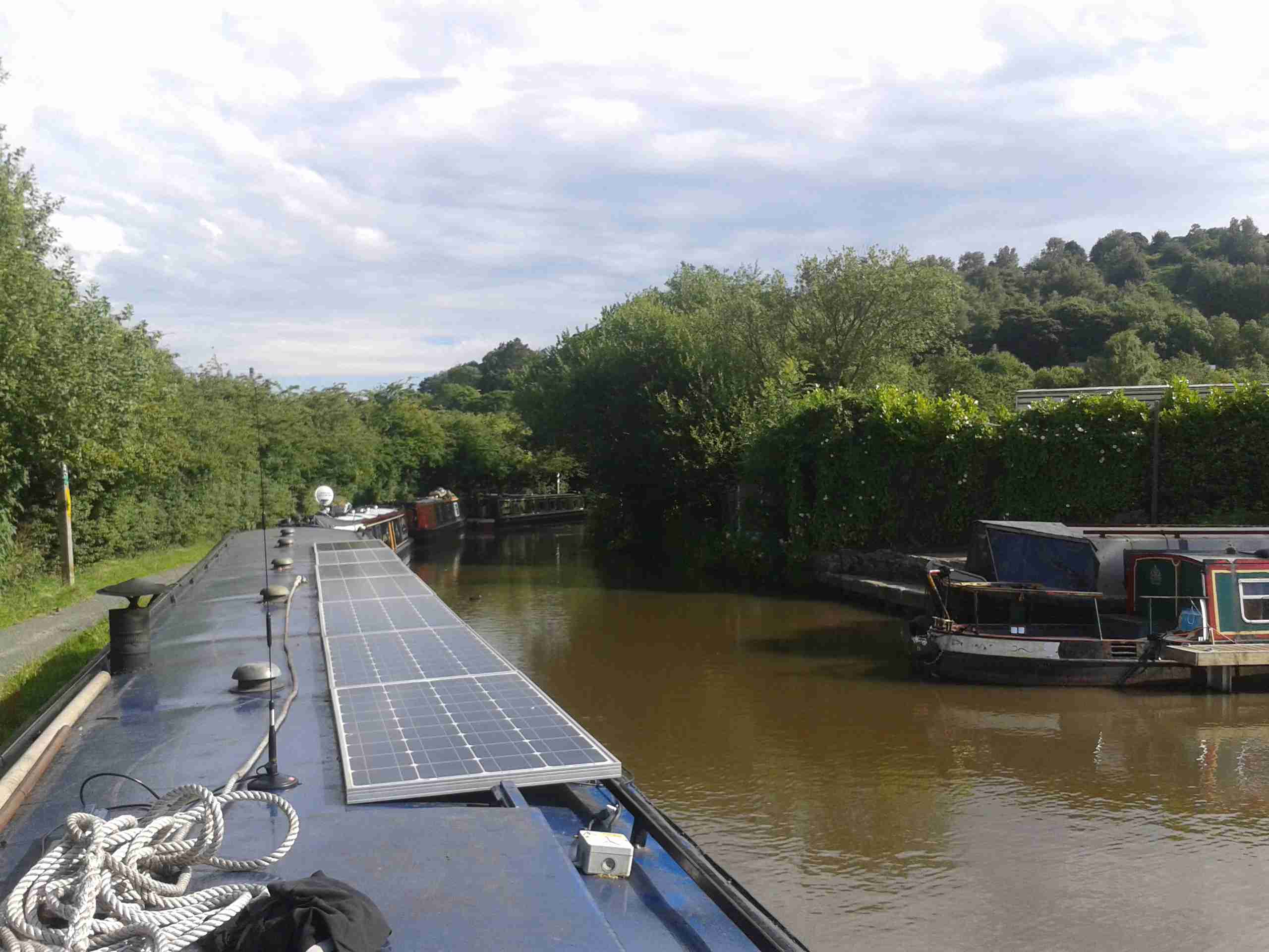
Antenna Magmount
I’ve got a Nagoya SP-80 antenna on a magmount for the radio, a magmount being used due to the many low bridges & trees on the canal. (It’s on the roof next to the first solar panel above). I prefer it to just fall over instead of having the antenna bend if anything hits it!
Part 2 will be coming soon with details of the permanent antenna feeder.
Here we go again with the GB3MR local idiot. He does always try to get a response from people, but we seem to be able to filter out this crap. 🙂 Here’s the audio for your listening pleasure. 🙂
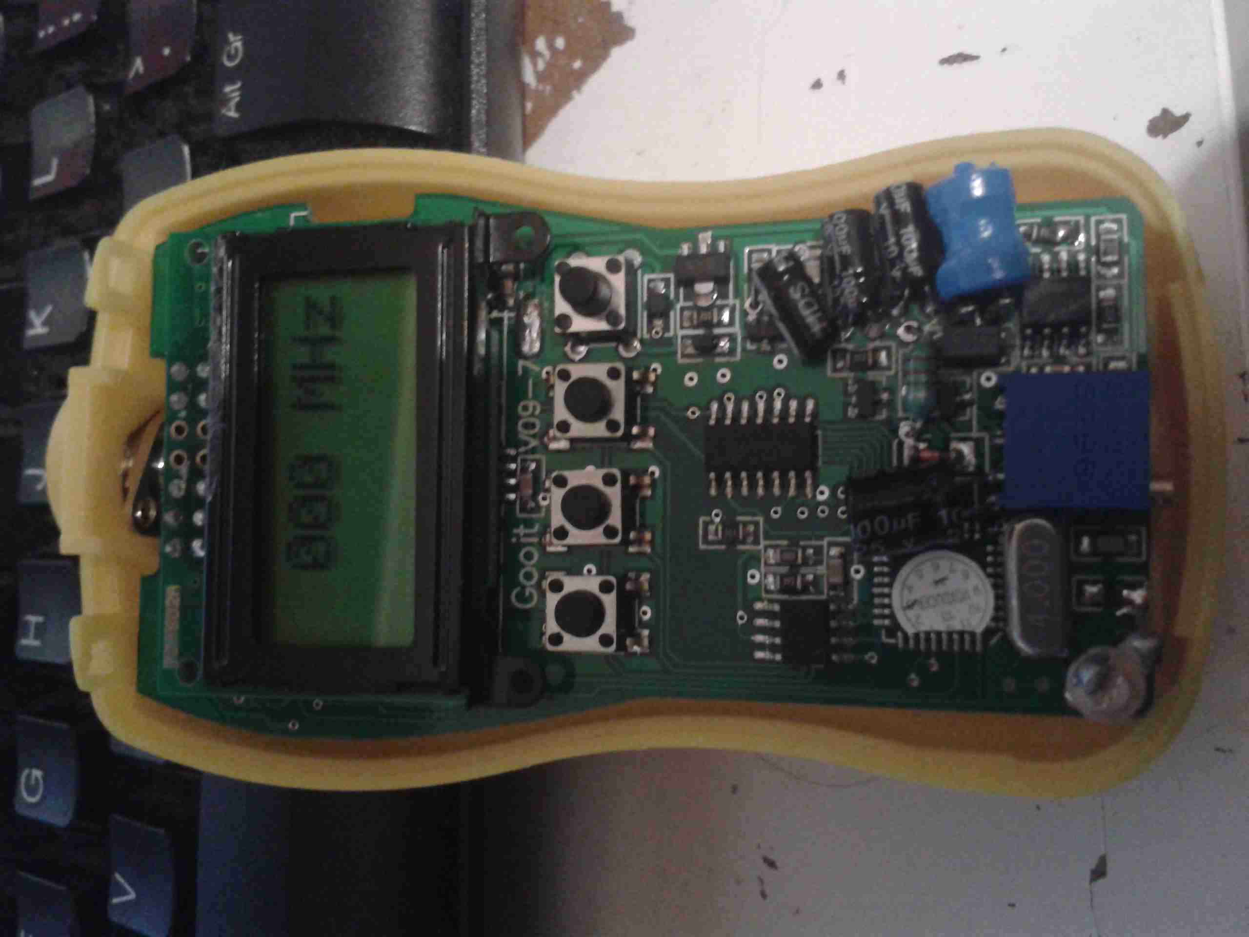
Unfortunately the manual for the eBay GY561 Frequency & RF Power Meter is very badly translated, but I think I have figured out the calibration procedure, so here it goes 🙂
Initial Screen
On removing the front cover, which is just clipped on, there are 4 buttons. The only button that is usually available is the one on the far right, the power button.
I will term these buttons A, B, C, D, starting from the left side.
To get into the initial calibration screen, in the above image, hold button A while the power button (D) is pressed. Release the power button (D), then release button A.
The meter will show the screen above, where the frequency to calibrate can be chosen. This goes in 5MHz steps, 0-500MHz, using the B button to go down in frequency, and the C button to go up.
Once you’ve selected the frequency you wish to calibrate against, press button A, and the following screen will appear:
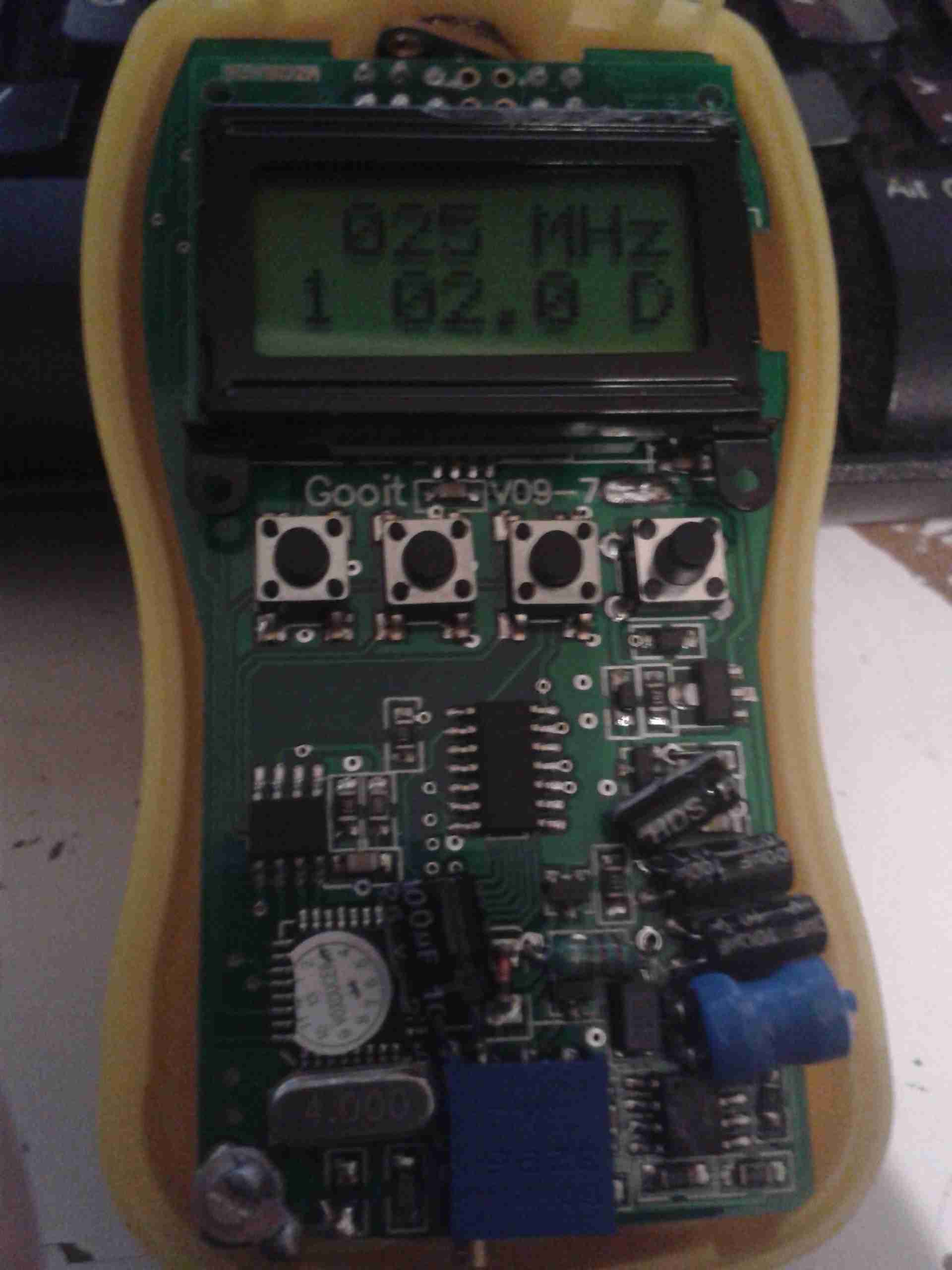
Frequency Calibration Screen
On this screen, the actual calibration can be done.
The number in the bottom left signifies the power level setting, from 1-5. The centre number is the calibration setting in Watts. The D in the bottom corner signifies that the setting is at the factory default.
Button C will cycle through the power level settings, for 2W, 5W, 10W 20W, 40W. This allows calibration at different power levels per frequency.
Once you have the frequency to calibrate, and you’ve selected the power level to calibrate at, connect a known RF power source to the input of the unit.
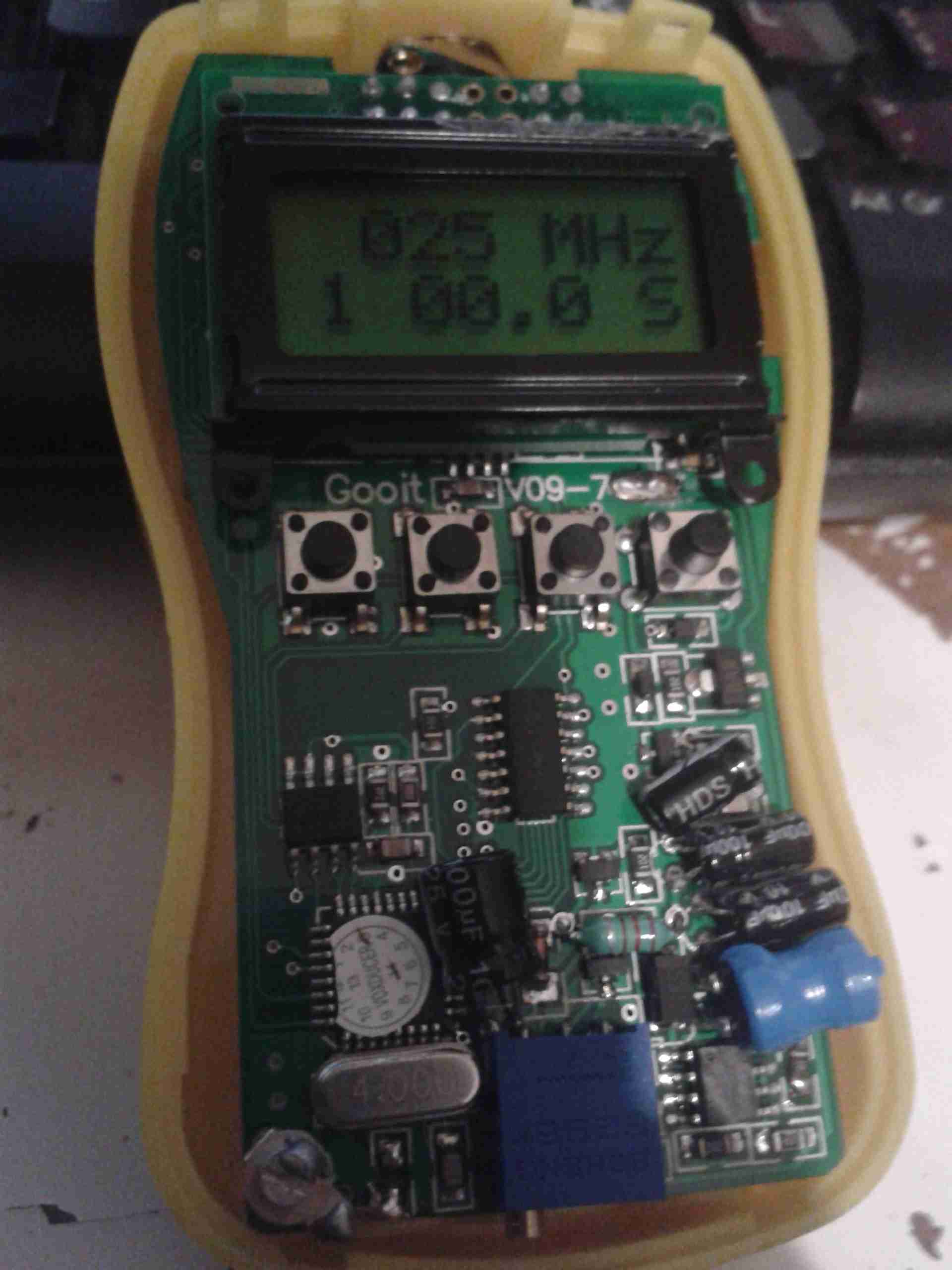
At this point, key the transmitter, and press button A. The display will change to the following:
Calibration Stage 2
When on this screen, you can set the power level of your RF source. Use the A key for +0.1W, the B key for +1W, and the C key for +10W.
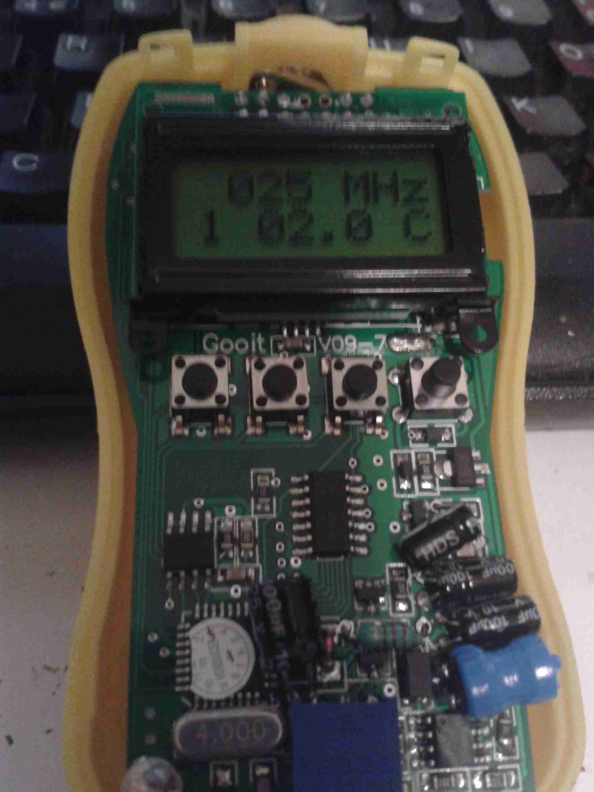
Once you’ve keyed in the power of your source, press button D to save the setting. The “S” in the bottom corner will change to a “C”, to indicate a user calibration has been entered:
Calibration Complete
If you make a mistake with entering the power level, press the “C” key to cycle up to 60W, once at this level, another press of the button will reset the reading to zero. You can then enter the power level again.
If you wish to revert a user-entered setting to the factory default, press button B on the page above. The “D” will reappear in the bottom corner to indicate the setting has been restored.
At this point you can either press button C to calibrate at another power level for this frequency, or press button D to go back to the frequency selection.
Press button D again when at the frequency selection page to turn the unit off. The unit will then power up normally next time the power button (D) is pressed.
One bit of my equipment that I’ve never looked into is my scanner, a handheld Uniden unit. I got this when Maplin Electronics had them on special offer a few years ago.
Uniden Scanner
Here’s the scanner itself, roughly the same size as a usual HT.
Back Cover Removed
Here the back cover has been removed, and the main RF board is visible at the top of the stack. Unfortunately the shielding cans are soldered on this unit, so no looking under there 🙁
On the right hand side of the board next to the antenna input is the main RF filter network, and it’s associated switching. The RF front end is under the shield closest to the front edge.
Controls & 3.3v Regulator
On the other side of the PCB is the Volume & Squelch potentiometers, along with a dedicated 3.3v switching supply. An NJM2360A High Precision DC/DC converter IC controls this one. A 3.3v test point is visible next to the regulator.
RF Board Reverse
Here’s the backside of the RF board, some more interesting parts here. There’s a pair of NJM3404A Single Supply Dual Op-Amp ICs, and a TK10931V Dual AM/FM IF Discriminator IC. This is the one that does all the back-end radio functionality. The audio amplifier for the internal speaker & external headphone jack is also on this PCB, top left. A board-to-board interconnect links this radio board with the main control board underneath.
Control PCB Front
Here’s the front of the control PCB, nothing much to see here, just the LCD & membrane keypad contacts.
Control PCB Reverse
And here’s the reverse side of the control board. All the interesting bits are here. The main microcontroller is on the right, a Renesas M38D59GF, a fairly powerful MCU, with onboard LCD drive, A/D converter, serial interface, 60K of ROM & 2K of RAM. It’s 6.143MHz clock crystal is just below it.
The mating connector for the RF board is in the centre here.
There is also a Microchip 24LC168 16KB I²C EEPROM next to the main microcontroller. This is probably for storing user settings, frequencies, etc.
EEPROM
The rest of this board is dedicated to battery charging and power supply, in the centre is a dual switching controller, I can’t figure out the numbers on the tiny SOT23 components in here, but this is dealing with the DC 6v input & to the left of that is the circuitry for charging the NiMH cells included with the scanner.
PSU
The last bit of this PCB is a BU2092FV Serial In / Parallel Out 4 channel driver. Not sure what this one is doing, it might be doing some signal multiplexing for the RF board interface. Unfortunately the tracks from this IC are routed on the inner layers of the board so they can’t be traced out.
A while ago I blogged about modifying the output voltage of some surplus Cisco switch power supplies to operate at 13.8v.
Since I was able to score a nice Hammond 1598DSGYPBK ABS project box on eBay, I’ve built one of the supplies into a nice bench unit.
Hammond ABS CaseSupply Unit
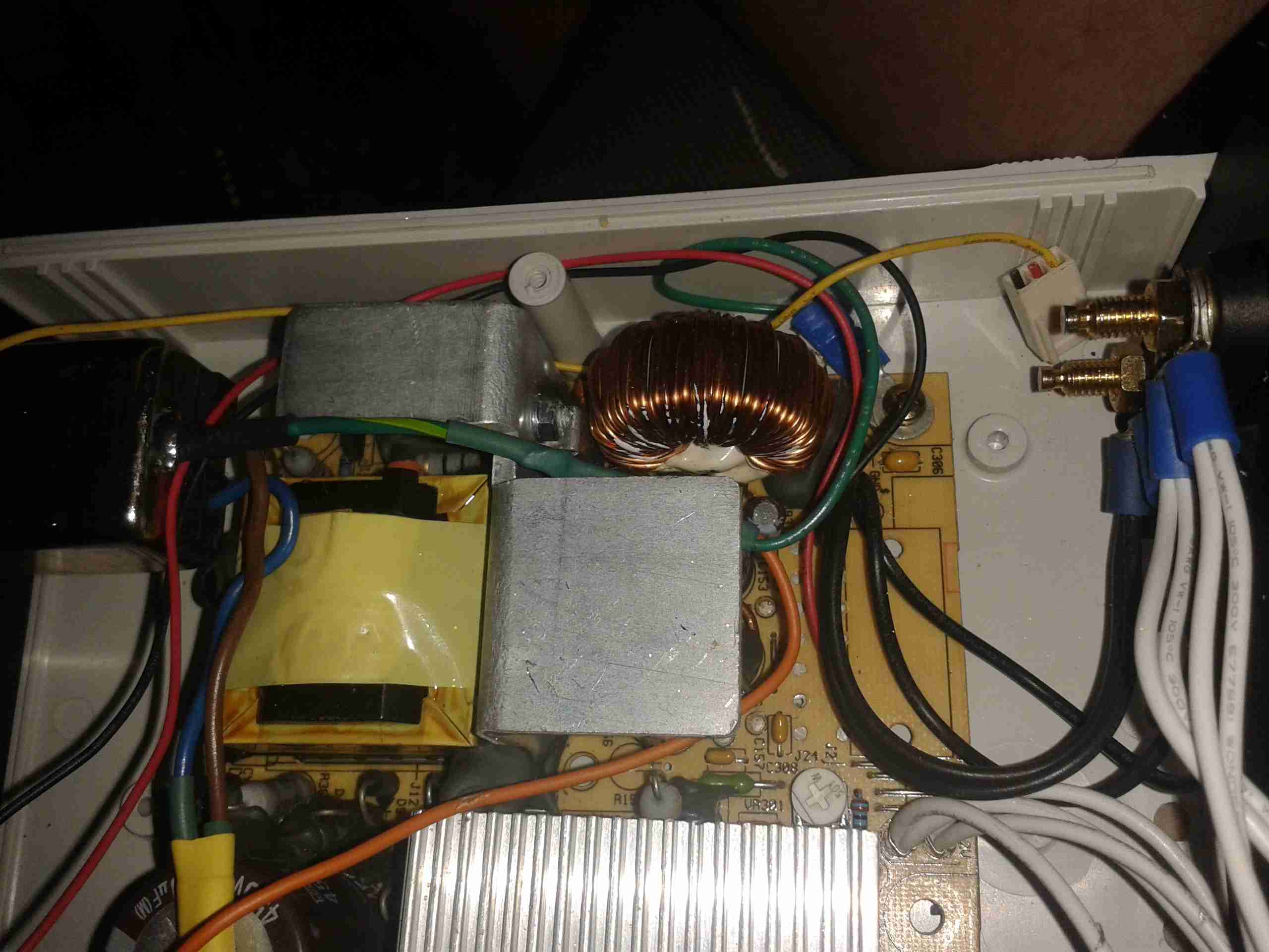
Above is the supply mounted into the box, I had to slightly trim one edge of the PCB to make everything fit, as it was just a couple of mm too wide. Luckily on the mains side of the board is some space without any copper tracks.
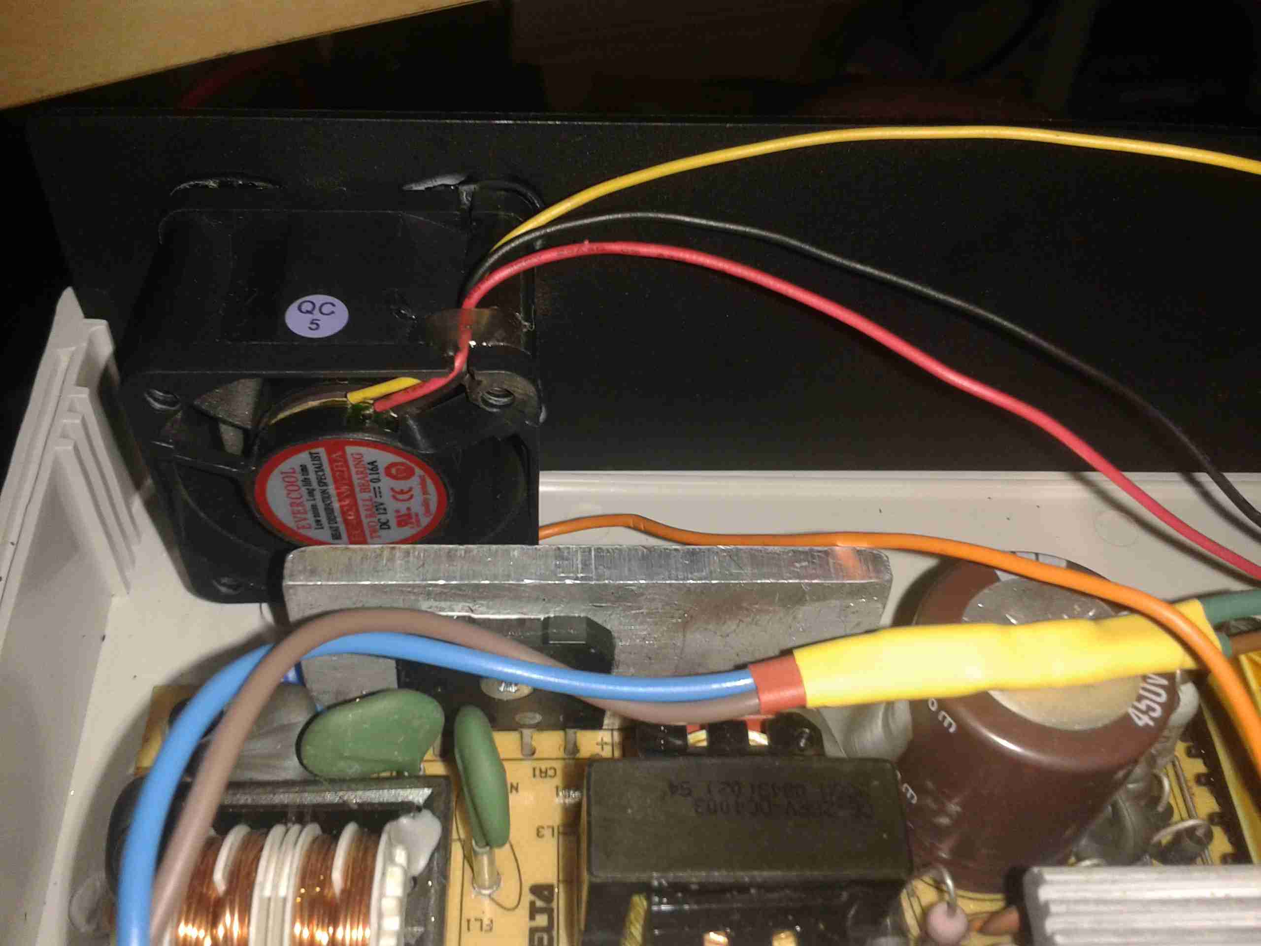
PSU Fan
These supplies are very high quality & very efficient, however they came from equipment that was force-air cooled. Running the PSU in this box with no cooling resulted in overheating. Because of this I have added a small 12v fan to move some air through the case. The unit runs much cooler now. To allow the air to flow straight through the case, I drilled a row of holes under the front edge as vents.
Output Side
Here is the output side of the supply, it uses standard banana jacks for the terminals. I have used crimp terminals here, but they are soldered on instead of crimped to allow for higher current draw. The negative return side of the output is mains earth referenced.
I have tried to measure output ripple on this supply, but with my 10X scope probe, and the scope set to 5mV/Div, the trace barely moves. The output is a very nice & stable DC.
This supply is now running my main radio in the shack, and is small enough to be easily portable when I move my station.
Tip Jar
If you’ve found my content useful, please consider leaving a donation by clicking the Tip Jar below!
All collected funds go towards new content & the costs of keeping the server online.