Unfortunately the manual for the eBay GY561 Frequency & RF Power Meter is very badly translated, but I think I have figured out the calibration procedure, so here it goes 🙂
On removing the front cover, which is just clipped on, there are 4 buttons. The only button that is usually available is the one on the far right, the power button.
I will term these buttons A, B, C, D, starting from the left side.
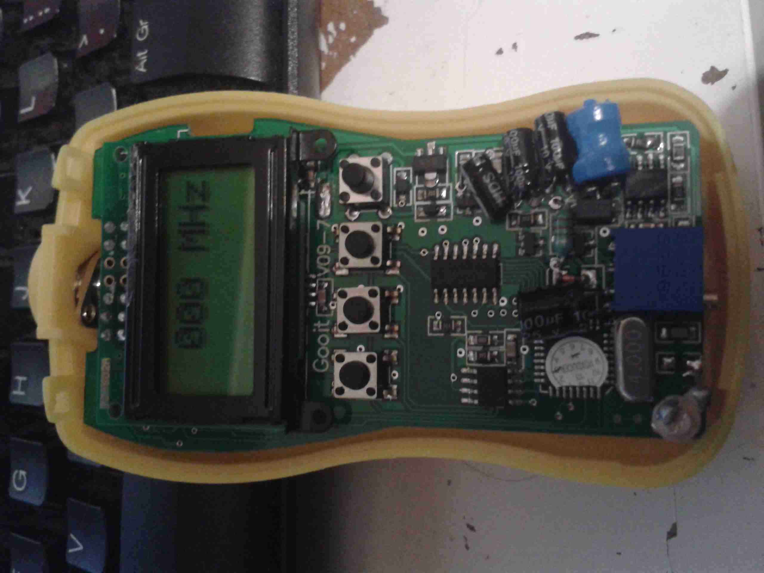
To get into the initial calibration screen, in the above image, hold button A while the power button (D) is pressed. Release the power button (D), then release button A.
The meter will show the screen above, where the frequency to calibrate can be chosen. This goes in 5MHz steps, 0-500MHz, using the B button to go down in frequency, and the C button to go up.
Once you’ve selected the frequency you wish to calibrate against, press button A, and the following screen will appear:
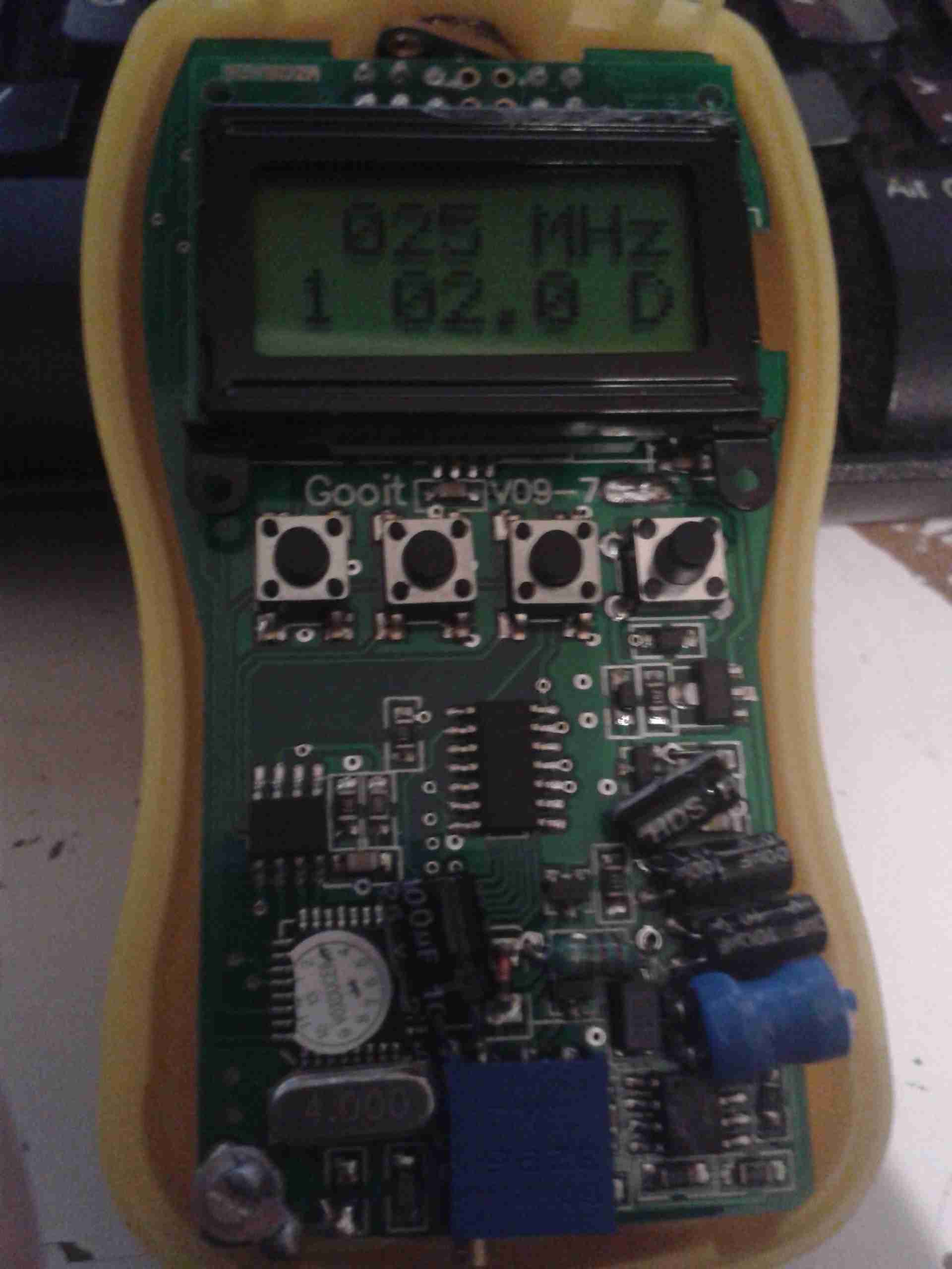
On this screen, the actual calibration can be done.
The number in the bottom left signifies the power level setting, from 1-5. The centre number is the calibration setting in Watts. The D in the bottom corner signifies that the setting is at the factory default.
Button C will cycle through the power level settings, for 2W, 5W, 10W 20W, 40W. This allows calibration at different power levels per frequency.
Once you have the frequency to calibrate, and you’ve selected the power level to calibrate at, connect a known RF power source to the input of the unit.
At this point, key the transmitter, and press button A. The display will change to the following:
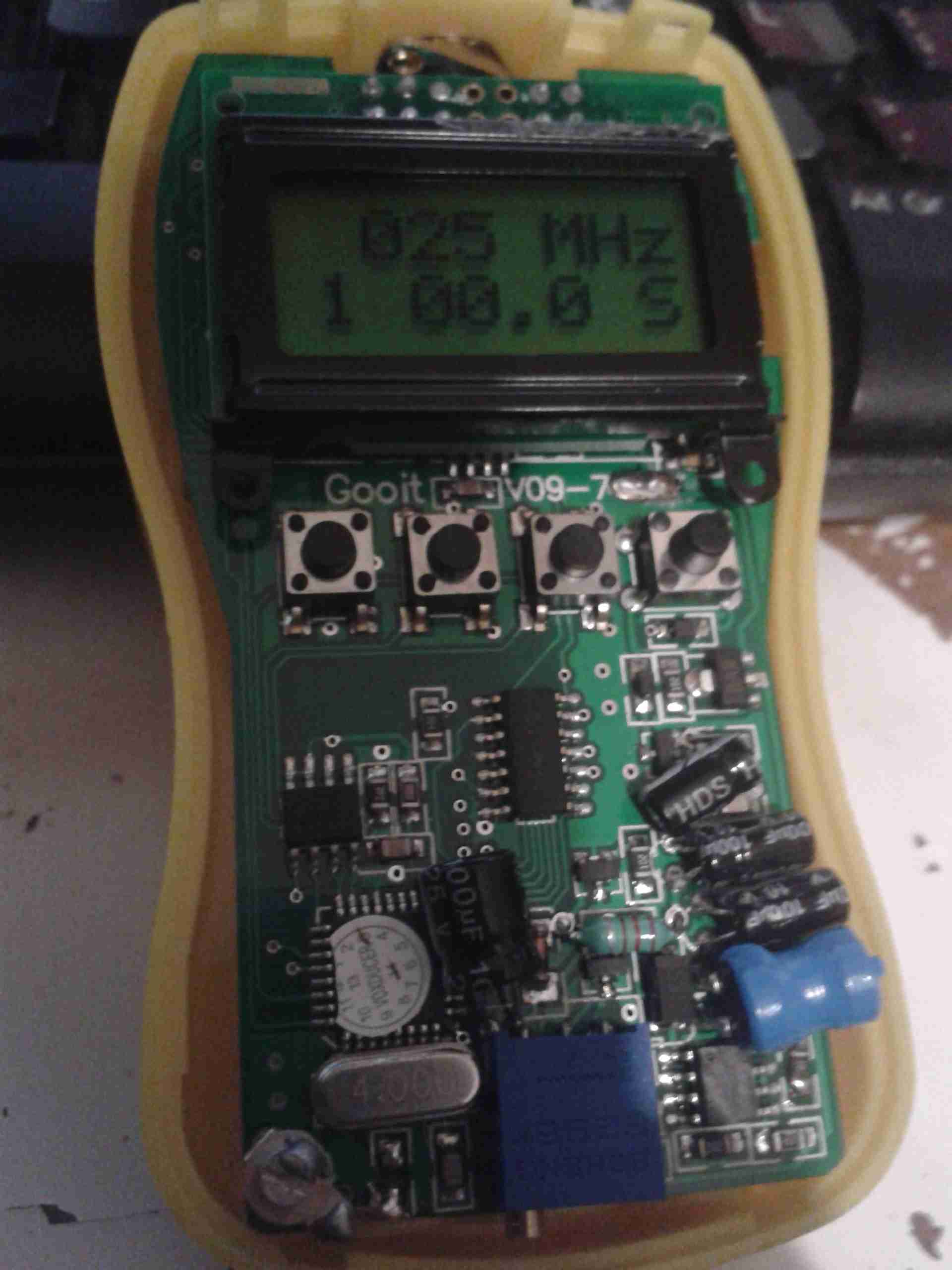
When on this screen, you can set the power level of your RF source. Use the A key for +0.1W, the B key for +1W, and the C key for +10W.
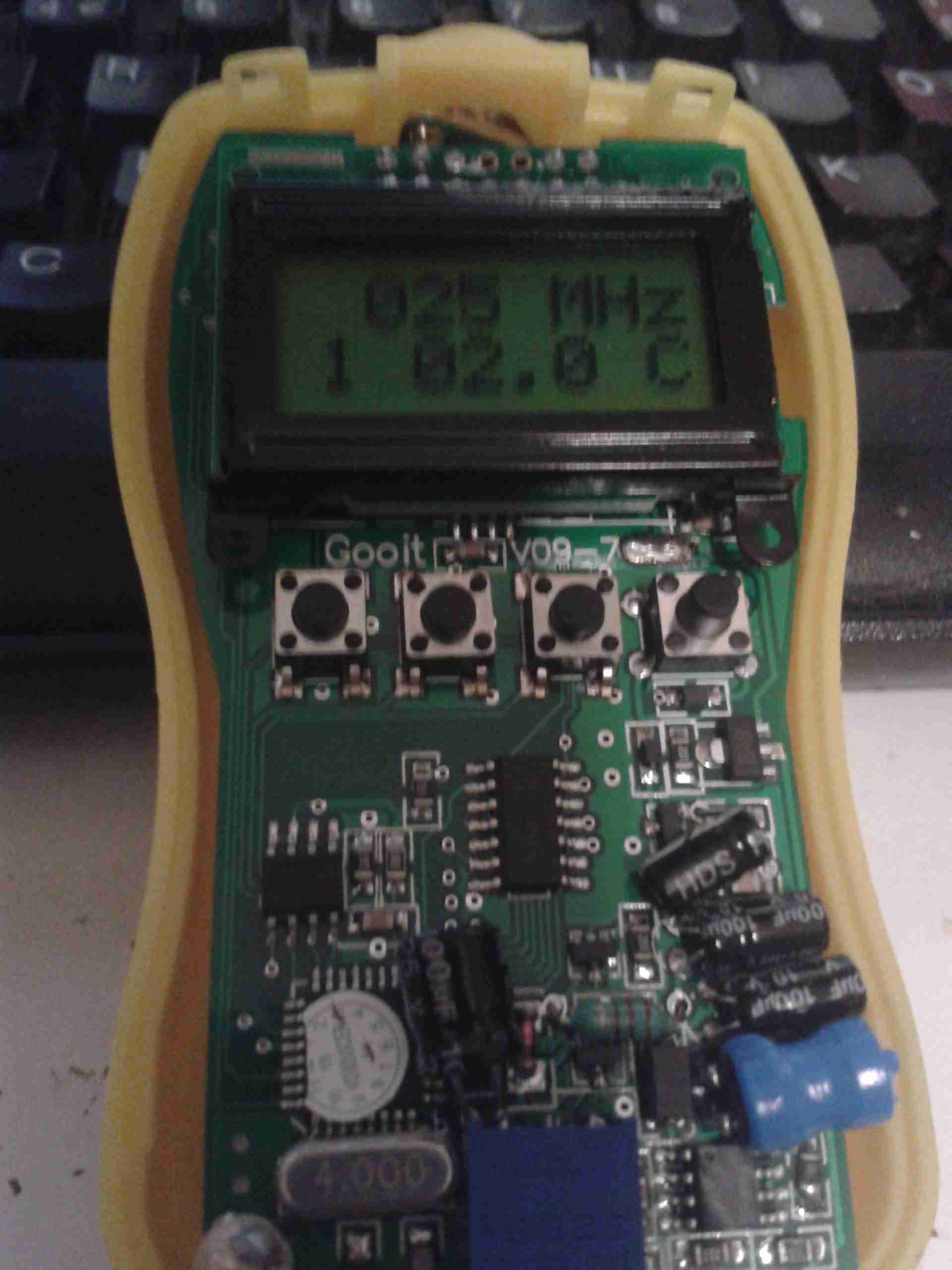
Once you’ve keyed in the power of your source, press button D to save the setting. The “S” in the bottom corner will change to a “C”, to indicate a user calibration has been entered:
If you make a mistake with entering the power level, press the “C” key to cycle up to 60W, once at this level, another press of the button will reset the reading to zero. You can then enter the power level again.
If you wish to revert a user-entered setting to the factory default, press button B on the page above. The “D” will reappear in the bottom corner to indicate the setting has been restored.
At this point you can either press button C to calibrate at another power level for this frequency, or press button D to go back to the frequency selection.
Press button D again when at the frequency selection page to turn the unit off. The unit will then power up normally next time the power button (D) is pressed.

I wonder if you were to replace the resistor with something like this if it would be better on the SWR. I just don’t care for the +-20ppm. But if you don’t do long keys it shouldn’t warm up that much.
http://sg.element14.com/vishay-dale/rh05050r00fc02/wirewound-resistor-50-ohm-50w/dp/1064034
I’m sure if the temp was monitored then the offset could be coded to compensate for longer keys under higher power.
Then again, I sort of want to take something like this since the receiver board that does the sampling uses a 1/2 watt resistor for the load, and swap it out with a 50W resistor so no attenuators should ne needed then?
http://www.ebay.com/itm/1-8000Mhz-OLED-RF-Power-Meter-55-5-dBm-1nW-2W-Power-Set-RF-Attenuation-Value-/131931412706?hash=item1eb7b998e2:g:YGUAAOSwvzRXz7Gq
Scott
The inductance of that Wirewound resistor would probably become an issue with RF, the impedance would not remain the same over a large frequency range, as a result the reading would drift. I’ve not seen that OLED power meter before, I’ll have to take a closer look at that, I don’t see why the 1/2W resistor couldn’t be replaced with a larger proper RF resistor to increase the power range though, although the calibration might be off. An attenuator probably will still be required though, somewhere in the circuit, as a higher wattage through the same 50Ω impedance requires a higher voltage. This might damage the RF front end on the meter. Might have to buy one of those & do an analysis on it at some point.
Cheers,
de 2E0GXE
Have you worked out a way to make the antenna side more sensitive? This will read the frequency if you tap the antenna to the antenna of the transmitter- but if you move just 1mm away it will not read.