Here’s one of the old modems from my spares bin, a Vodafone Mobile WiFi R207. This is just a rebranded Huawei E5330. This unit includes a 3G modem, and a WiFi chipset, running firmware that makes this a mini-router, with NAT.
Specs
The back has the batter compartment & the SIM slot, with a large label showing all the important details.
Cover Removed
A couple of small Torx screws later & the shell splits in half. All the electronics are covered by shields here, but luckily they are the clip-on type, and aren’t soldered direct to the PCB.
Chipset
Once the shield has been removed, the main chipset is visible underneath. There’s a large Spansion MS01G200BHI00 1GBit flash, which is holding the firmware. Next to that is the Hi6758M baseband processor. This has all the hardware required to implement a 3G modem. Just to the right is a Hi6521 power management IC, which is dealing with all the power supplies needed by the CPU.
The RF section is above the baseband processor, some of which is hiding under the bits of the shield that aren’t removable.
SIM Socket
There’s a socket onboard for a standard Mini-SIM, just to the left of that is a Hi6561 4-phase buck converter. I would imagine this is providing the power supplies for the RF section & amplifier.
Unpopulated Parts
Not sure what this section is for, all the parts are unpopulated. Maybe a bluetooth option?
PCB Reverse
The other side of the PCB is pretty sparse, holding just the indicator LEDS, button & the WiFi Chipset.
Realtek WiFi Chipset
The chipset here is a Realtek part, but it’s number is hidden by some of the shield. The antenna connection is routed to the edge of the board, where a spring terminal on the plastic case mounted antenna makes contact.
Being in technology for a long time, I have seen my fair share of disk failures. However I have never seen a single instance where SMART has issued a sufficient warning to backup any data on a failing disk. The following is an example of this in action.
Toshiba MQ01ABD050
Here is a 2.5″ Toshiba MQ01ABD050 500GB disk drive. This unit was made in 2014, but has a very low hour count of ~8 months, with only ~5 months of the heads being loaded onto the platters, since it has been used to store offline files. This disk was working perfectly the last time it was plugged in a few weeks ago, but today within seconds of starting to transfer data, it began slowing down, then stopped entirely. A quick look at the SMART stats showed over 4000 reallocated sectors, so a full scan was initiated.
SMART Test Failure
After the couple of hours an extended test takes, the firmware managed to find a total of 16,376 bad sectors, of which 10K+ were still pending reallocation. Just after the test finished, the disk began making the usual clicking sound of the head actuator losing lock on the servo tracks. Yet SMART was still insisting that the disk was OK! In total about 3 hours between first power up & the disk failing entirely. This is possibly the most sudden failure of a disk I’ve seen so far, but SMART didn’t even twig from the huge number of sector reallocations that something was amiss. I don’t believe the platters are at fault here, it’s most likely to be either a head fault or preamp failure, as I don’t think platters can catastrophically fail this quickly. I expected SMART to at least flag that the drive was in a bad state once it’s self-test completed, but nope.
Internals
After pulling the lid on this disk, to see if there’s any evidence of a head crashing into a platter, there’s nothing – at least on a macroscopic scale, the single platter is pristine. I’ve seen disks crash to the point where the coating has been scrubbed from the platters so thoroughly that they’ve been returned to the glass discs they started off as, with the enclosure packed full of fine black powder that used to be data layer, but there’s no indication of mechanical failure here. Electronic failure is looking very likely.
Clearly, relying on SMART to alert when a disk is about to take a dive is an unwise idea, replacing drives after a set period is much better insurance if they are used for critical applications. Of course, current backups is always a good idea, no matter the age of drive.
As I mentioned in the previous post, these heaters have a standard interface that’s used for control & diagnostics, the W-Bus. This is transmitted over the K-Line of the vehicle bus, and all heaters, regardless of firmware modifications done by the various car manufacturers respond to this interface. Official Webasto diagnostic adaptors are available, but these are just a very expensive serial adaptor. A much cheaper option is a ~£5 Universal ODB adaptor.
ODB2
Above shows the signals on the ODB connector – the ones we’re interested in here are Pin 16, the +12v supply, and Pin 7, K-Line. Connect Pin 16 to the positive supply to the heater, and Pin 7 to Pin 2 on the Webasto heater. (Valid for all TT-V heaters).
Device Selection
Once these two connections are made to the heater, fire up the Thermo Test software. The screen above will be displayed. Pick W-Bus at top left.
COM Port Selection
First thing, connect the ODB adaptor to USB, and change to the correct COM port in Thermo Test. There may be several in the list, but a newly connected USB device should show up with the highest COM number.
Thermo Test
Once Thermo Test is running, start communications by going to the Diagnosis Menu > Start Diagnostic (F2 keyboard shortcut).
Initialized
After a few seconds, communication will be established. This will show faults, if any are present, and allow testing of the heater & it’s component parts. A summary report can be generated with Diagnosis > View Summary:
Diagnosis report                                               Webasto Thermosystems
------------------------------------------------------------------------------------------


Configuration:
--------------
  W-Bus version...............................................................3.3
  Device name.............................................................X204 SH
  W-Bus code.......................................................715CC0E73F8000
  Fuel type................................................................Diesel
  Circulating pump in control idle period.......................................0
  Heating duration limitation.................................................255 [min]
  Factor for shortening of ventilation duration...............................1/1
  Device identification number..........................................09007236E
  Dataset identification number.......................................09006806H05
  Software identification number........................................000000000
  HW version................................................................51/03
  SW version..................................................Tuesday/07/04 12.12
  SW version (EEPROM).........................................Tuesday/07/04 12.12
  Date of manufacture control unit.......................................27.10.03
  Date of manufacture heater.............................................04.02.04
  Customer identification number.....................................4R8318K463AE
  Serial number........................................................0000123626
  Test signature.............................................................4B42
  Minimum voltage threshold....................................................10 [V]
  Maximum voltage threshold....................................................16 [V]
  Delay for supply voltage min. detection......................................20 [s]
  Delay for supply voltage max. detection.......................................6 [s]

Operating data:
---------------
  Working hours.............................................................44:03 [h:m]
  Operating hours.........................................................5388:08 [h:m]
  Start count...............................................................19129
  Burning duration PH 1..33%.................................................0:00 [h:m]
  Burning duration PH 34..66%................................................0:00 [h:m]
  Burning duration PH 67..100%...............................................0:00 [h:m]
  Burning duration PH >100%..................................................0:00 [h:m]
  Burning duration SH 1..33%.................................................0:00 [h:m]
  Burning duration SH 34..66%................................................0:00 [h:m]
  Burning duration SH 67..100%...............................................0:00 [h:m]
  Burning duration SH >100%..................................................0:00 [h:m]
  Working duration PH........................................................0:51 [h:m]
  Working duration SH......................................................121:10 [h:m]
  Start counter PH..............................................................6
  Start counter SH............................................................854
  Ventilation duration.......................................................0:00 [h:m]

Error:
------

------------------------------------------------------------------------------------------
12.03.17  17:17:30                                       Webasto Thermo Test  2.16.1
This shows all the important stuff, including running hours. (5388Hrs on this heater!). Most importantly, there are no faults listed.
Heater Running
The heater can be fully tested by issuing a start command from the Command Menu > Parking Heating option. Obviously cooling water will be required for this, along with an external water pump. (The water pump control output on these heaters seems to be totally disabled in firmware, as they rely on the engine’s coolant pump). I used a bucket of water along with a small centrifugal pump to provide the cooling. During this test I noted that the firmware is much more aggressive in these units. The marine versions shut down at ~72°C water temperature, whereas these don’t so the same until ~90°C.
Now I’ve managed to communicate with the heater, I’ll get onto building a standalone controller so I can dispense with the Windows VM for control.
This is another automotive part, this one was found lurking inside an LCD info display from a BMW. I didn’t manage to find a datasheet for this one, the neither the part number on the package or the wafer code on the die itself revealed anything.
As one of my current projects involves a small petrol engine – a Honda GX35 clone, I figured an hour counter would be very handy to keep an eye on service intervals. (More to come on the engine itself later on). I found a device that would suit my needs on good old eBay.
Inductive Engine Monitor
These engine monitors are pretty cheap, at about £4. The sensing is done by a single heat-resistant silicone wire, that wraps around the HT lead to the spark plug. The unit can be set for different firing intervals via the buttons. In the case of most single-cylinder 4-stroke engines, the spark plug fires on every revolution – wasted-spark ignition. This simplifies the ignition system greatly, by not requiring the timing signal be driven from 1/2 crankshaft speed. The second “wasted” spark fires into the exhaust stroke, so has no effect.
Internals
The back cover is lightly glued into place with a drop of cyanoacrylate in opposite corners, but easily pops off. The power is supplied by a soldered-in 3v Lithium cell. The main microcontroller has no number laser etched on to it at all – it appears it skipped the marking machine.
Input Filtering
The input from the sensing wire comes in through a coupling capacitor & is amplified by a transistor. It’s then fed into a 74HC00D Quad 2-Input NAND gate, before being fed into the microcontroller.
Pickup
The pickup wire is simply wound around the spark plug lead. I’ve held it in position here with some heatshrink tubing. Heat in this area shouldn’t be an issue as it’s directly in the airflow from the flywheel fan.
I have found myself needing some more in the way of High Voltage supplies of late, with the acquisition of the new He-Ne laser tubes, so I went trawling eBay for something that would be suitable to run these tubes. (I currently only have a single He-Ne laser PSU brick, and they’re notoriously hard to find & rather expensive).
This supply is rated at 1kV-10kV output, at 35W power level. Unfortunately this supply isn’t capable of sustaining the discharge in a large He-Ne tube, the impedance of the supply is far too high. Still, it’s useful for other experiments.
The flyback-type transformer clearly isn’t a surplus device from CRT manufacture, as there are very few pins on the bottom, and none of them connect to the primary side. The primary is separately wound on the open leg of the ferrite core.
Drive Electronics
The drive electronics are pretty simple, there’s a controller IC (with the number scrubbed off – guessing it’s either a 556 dual timer or a SMPS controller), a pair of FDP8N50NZ MOSFETs driving the centre-tapped primary winding.
The drive MOSFETs aren’t anything special in this case: they’re rated at 500v 8A, 850mΩ on resistance. This high resistance does make them get rather hot even with no load on the output, so for high power use forced-air cooling from a fan would definitely be required.
Test Setup
Here’s the supply on test, I’ve got the scope probes connected to the gate resistors of the drive MOSFETs.
Waveforms
On the scope the primary switching waveforms can be seen. The FETs operate in push-pull mode, there’s a bit of a ring on the waveform, but they’re pretty nice square waves otherwise.
Arc
At maximum power on 12v input, about 25mm of gap is possible with an arc.
SG-HM2 is a modular He-Ne laser power supply based on IC-HI1 with some minor enhancements. The first version is for laser tubes up to approximately 1 mW (2 mW with trivial modifications) but it should be straightforward to go to 5 mW or even higher power tubes by replacing the SG-HM2 HV Module (HVM2-1) with one with a higher voltage and current rating, along with a higher power MOSFET and minor component value changes to the Control Module (suggestions below). I have added an adjustment for tube current, a current limiting resistor and Zener to protect against output short circuits, an enable input (ground to turn on), a bleeder resistor to virtually eliminate the shock hazard after the power supply is turned off, and power and status LEDs.
Get the schematic for SG-HM2 (1 mW version) in PDF format: [download id=”5610″]
Modifying SG-HM2 for Higher Power He-Ne Laser Tubes
The following are guidelines for modifying SG-HM2 to drive various power He-Ne lasers. The PCB layout below with two versions of the HV Module should accommodate He-Ne laser tubes up to 10 mW. All assume input of around 12 V though a higher power system can generally run lower power lasers at reduced input voltage. If operation at rated power on another input voltage is desired, the number of turns on the inverter transformer can be adjusted accordingly. As noted above, the 1 mW HV Module (HVM2-1) should run tubes up to about 2 mW, though increasing the µF values of some of the HV capacitors may be desirable to reduce ripple at the higher tube current. Minor changes may also be needed in the components on the SG-HM2 Control Module including using a higher power MOSFET for Q1 and reducing the values of R7 and/or R8 for the higher tube current. Or, just populate the Control Module with Q1 being an IRF644, R7 being 150 ohms, and R8 being 750 ohms for compatibility with all the HV modules. For that matter, the HVM2-5 PCB HV Module should be usable with lower power lasers.
   Laser Power       1 mW         2 mW         5 mW         10 mW
-----------------------------------------------------------------------
   Voltage           1200 V       1500 V       2300 V       3500 V
   Current           2-4mA        3-5mA        5-7mA        5-7mA

 SG-HM2 HV Module:

   PCB Version       HVM2-1       HVM2-1       HVM2-5       HVM2-5

   T101
    Core (DxH)       18x11 mm     18x11 mm     26x16 mm     26/16 mm
    Primary          9T,#28       9T,#28       9T,#26       9T,#26
    Secondary        450T,#40     450T,#40     600T,#40     900T,#40
     Res. (Est)      60 ohms      60 ohms      (90 ohms)    (120 ohms)

   D101-106          2kV          2kV          3kV          5kV

   C101-104          1nF,3kV      2nF,3kV      2nF,6kV      2nF,6kV
   C105              47pF,3kV     47pF,3kV     100pF,6kV    100pF,6kV
   C106              3nF,10kV     5nF,10kV     6nF,15kV     6nF,15kV

   R102              10K,1/2W     10K,1/2W     10K,1W       10K,1W
   R103              200M,10kV    200M,10kV    200M,15kV    200M,15kV
   R106-107 (total)  10M          10M          15M          20M

 SG-HM2 Control Module:

   Q1              IRF630       IRF630       IRF640       IRF644
   R7              300          250          150          150
   R8              500          250          100          100
SG-HM2 Inverter Transformer
The inverter transformer for HVM2-1 is wound on a ferrite pot core with a small air-gap (about 0.005″). It is 18 mm in diameter by 11 mm high. While specified to use a 9 turn primary and 450 turn secondary, these values can be adjusted somewhat to handle various input and output requirements. Don’t go much lower on the primary as this may result in core saturation. The 9/450 transformer should be fine for 1 to 2 mW He-Ne laser tubes running on 8 to 15v DC input. With 9/300, it will operate on about 12 to 20v DC. Increasing the number of secondary turns (e.g., 9/600) may result in operation on a slightly lower input voltage, but probably not by much. The 9/450 transformer may even run He-Ne laser tubes larger than 2 mW but I haven’t yet tested this since I haven’t built a prototype of HVM2-5 as yet.
It doesn’t matter very much whether the primary (P) is wound first or the secondary (S) is wound first though the former appears to work slightly better, running the tube at about 8v DC input instead of 9v DC input for the same 9/450 transformer. P over S is slightly easier to wind since the primary doesn’t get in the way and increase the lumpiness of the secondary layers. However, with S over P, insulation is somewhat less critical since the HV lead is out away from anything else. With the P over S, additional insulation is needed between them. Also, since the primary coil is larger diameter, it will have more resistance and there will be greater inter-winding capacitance (though probably not significant). The secondary should be constructed as multiple layers of about 50 or 60 turns each, with insulating tape between layers. Each should be wound in as close to a single layer as possible with alternating layers staggered to prevent arc-over. This doesn’t have to be perfect but try to go gradually from one side to the other to keep wires at high relative potential away from each other. Make sure the HV output leads (particularly the one away from the dot) are well insulated as they exit the transformer. And, as noted, if the primary is over the secondary, there must be high voltage insulation between them. The peak output voltage when the MOSFET turns off (the flyback pulse) may be more than 5 times higher than what would be expected from the DC input voltage and the turns-ratio alone – several kV and this *will* try to find a path to ground! There are more detailed transformer construction instructions in the next section.
Note that this transformer is slightly larger physically than the one from IC-HI1. This is for two reasons: (1) It is easier to wind with more space and a larger wire size for the secondary, and (2) continuous operation should be possible with 2 mW laser tubes, which might have been marginal with the original transformer used in IC-HI1. A by-product of the larger core is that its 9 turn primary should be roughly equivalent to the 12 turn primary of the smaller core in terms of inductance and core saturation limitations.
Interestingly, a similar transformer found in a different commercial power supply, had no insulating tape anywhere. It would appear that with very precise machine-wound HV secondary, done first, the voltage is distributed so uniformly that this is unnecessary.
I’ve now built and tested several transformers in IC-HI1, removing the original transformer and installing socket pins so either the original or an adapter board can be plugged in. This setup is then equivalent to SG-HM2 with the HVM2-1 HV Module. The minimum input voltage values that follow are when driving a 0.5 mW He-Ne laser tube:
           Turns        Pot Core   Vin (VDC)
   ID   P/S    Order    (DxH mm)   Min  Max           Comments
 ------------------------------------------------------------------------------
   1* 12/600  S over P    14x8     7.5  15   Original IC-HI1 transformer
   2  12/350  S over P    18x11    14   22   First prototype, described above
   3   9/350  S over P    18x11    11   18   #2 with 3 P T added out-of-phase
   4   9/425  P over S    18x11     9   16
   5   9/450  P over S    18x11     9   16
   6   9/450  S over P    18x11     8   15
   7  12/500  P over S    26x16     8   15
*The number of turns on the original (#1) is not really known exactly and may be lower or higher by up to 25 percent based on the measured secondary resistance (45 ohms) and estimated wire size (somewhere between #38 and #40. (Even with the larger wire, the amount of bobbin area taken up by the wire is less than 50 percent so it should fit even with many layers of insulating tape. The transformer is Epoxy impregnated and likely to be impossible to disassemble into any form that can be analyzed!)
All of these transformers will drive He-Ne laser tubes of up to at least 2.5mW using the equivalent of the HVM2-1 HV Module which is part of IC-HI1. Even with the 2.5mW tube, the minimum operating voltage was only about 0.5v higher than for the 0.5mW tube. There is a good chance they would drive even larger He-Ne laser tubes (though possibly at a slightly higher input voltage) but I don’t dare try using the existing HV circuitry as it might not survive for long. I suspect that transformers #4, #5, and #6 would run on an input voltage of less than 8v DC but the salvaged cores I am using have a larger air-gap than might be optimal and I don’t have anything to reduce it without heavy losses. They attempt to start the tube at around 6v DC but are unable to maintain it and flicker rapidly. (#2 and #3, which use the same style core, would also benefit somewhat.) Operation using #1 and #5 is virtually identical, with the original running at perhaps 0.5v DC less input. I expect they would be even more identical if the air-gap on #5 were smaller, and #6 with its smaller air-gap does indeed run at the lower input voltage. I haven’t actually confirmed that anything blows up above the maximum voltages listed above, which were arbitrarily chosen. But I am guessing that bad things might happen at some point. 🙂
I have also constructed a transformer which will need to be used with HVM2-5: 12/1200, P over S, on a 30×19 pot core. I will also construct a 9/900. S over P, on a 30×19 pot core (or on a 26×16 if I can find one). Testing of these will have to await an HVM2-5 prototype.
SG-HM2 Transformer Construction
Here are details on construction of the inverter transformer for SG-HM2. With all parts and tools on hand, it takes about an hour start to finish. Only a small portion of this time is in the actual winding (at least if a coil winding machine is used). Most of the time is spent in adding the insulation tape and terminating the leads. After constructing a few of these, it does go quicker. 🙂
Step-by-step instructions are provided for the HVM2-1 transformer. The changes needed for HVM2-5 are summarized at the end of this section. Some sort of coil winding machine is almost essential as #40 wire is extremely thin and easy to break. (Anything larger than #40 will not fit on the bobbin.) It doesn’t have to be fancy. Mine is probably 50 years old of the type that is (used to be?) advertised in the back of electronics magazines. However, a couple of spindles – one that is fixed or free to rotate for the wire supply and the other which can be turned for the coil being wound – are really all that are needed. Don’t use any sort of powered approach though (unless you have a *real* professional coil winder!) as it is all too easy to break the wire if there is no tactile feedback to detect snags.
Parts required for T101 of HVM2-1:
18×11 mm (1811) ferrite pot core with a small air-gap (no more than 0.005″) or no air-gap, and a single section bobbin. These are available from several manufacturers but surplus or salvaged cores may be easier to obtain. Radio Shack used to have a “ferrite kit” which included a variety of sizes of cores (only 1 each though so you’d have to buy two kits and there were no bobbins!). I doubt the kit still exists though.
Approximately 1.5 feet of #28 magnet wire for the primary (9 turns wound first) and approximately 60 feet of #40 magnet wire for the secondary (450 turns wound on top of the primary). I found both these size wire in various solenoids and relays I’ve discombobulated. 🙂 Wire sizes aren’t critical but these are known to fit and the #40 can be handled with a reasonable chance of not breaking.
Sleeving to protect the primary wires where they leave transformer. I used approximately 2″ of insulation (each lead) from the individual wires in some 25 pair phone cable.
Wirewrap wire or other thin insulated wire to terminate the secondary wires where they leave the transformer.
Insulating tape. 1 mil Mylar or similar is desirable. However, I’ve found that thin clear (non-reinforced) packing tape does an adequate job, though it probably doesn’t have as much dielectric strength as real insulating tape so additional layers are required. It will also likely not stand up to overheating too well. Electrical tape is way too thick and would prevent enough turns from fitting.
A piece of Perf. board with holes on 0.1″ centers, 0.8″x0.8″. There should be 7 rows of holes each way so that one hole lines up in the center.
A Nylon 4-40 screw and nut to fasten the transformer to the board.
Four (4) machined-type IC socket pins or something similar to use as terminals.
Wind the primary:
Slip a piece of sleeving over the start of the primary wire and position the sleeving so it extends about 1/2 turn inside the bobbin on the left side.
Wrap exactly 9 turns of this wire clockwise around the bobbin, left to right. The wires should enter and exit on the same angular position (slot) of the bobbin on opposite sides.
Slip another piece of sleeving over the wire end exiting the bobbin so that it too is about 1/2 turn inside the bobbin.
Wrap 1.5 to 2 turns of tape tightly over the primary winding to secure and insulate it.
Wind the secondary:
Strip 1/8″ or so from the end of a 2″ piece of wire-wrap wire and solder the start of the wire for the secondary winding to it. Make sure the insulation on the fine magnet wire has been removed – usually just heating it while soldering will do this. Leave an inch or so of the magnet wire extending from the connection so that continuity can be confirmed with a multimeter, then snip it off. Install this in the opposite slot of the bobbin also on the left side with about 1/4″ of insulation inside the bobbin against the side and separated from the primary. Leave a little slack in the fine secondary wire so that slight motion won’t break it. Add a small piece of tape to protect and insulate this connection.
Using your coil winding machine (you do have one, correct?), build up the secondary in layers of about 50 to 75 turns in a counter-clockwise direction (bobbin being rotated clockwise). A single layer of wire won’t fit in the 1/8″ or so available (in the 18×11 mm core bobbin) so there will have to be some overlap. But, do this several times across the layer so that any given wire won’t be next to one with a much different voltage. In other words, wind a few turns and back up so that there will in essence be multiple sub-windings of 5 or 10 turns, repeated several times across the layer. Keep the wire at least 1/32″ away from either edge of the bobbin.
After each full layer or wire, add just over 1 layer of insulating tape making sure it covers the entire width of the bobbin. There should be just enough overlap to assure there is at least 1 layer of insulation but not much more as excessive tape will end up taking up too much space.The entire 450 turn winding will then require 6 to 9 full layers. Add another layer of insulating tape over the last winding layer leaving the wire end exposed.
Terminate the end of the secondary winding with another piece of thin wire by soldering as above. Confirm continuity with a multimeter. For the 450 turn secondary, the resistance should be about 60 ohms. Add a piece of thicker sleeving over this at the HV end if space is available. Else, use some bits of tape to insulate the wirewrap wire lead from the core and exposed inner layers that it may come near as it exits out the side of the bobbin. Add another layer of tape to secure the lead in place.
Add several more layers of insulating tape to complete the bobbin assembly.
Prepare the mounting board:
Widen the center hole to 7/64″ to accommodate a 4-40 nylon screw.
Widen the holes at the 4 corners of the board to accept the 4 IC socket pins (if used) as a press-fit or glue them in place with 5 minute Epoxy or SuperGlue.
Final assembly:
Install the ferrite pot core halves to the bobbin taking care not to crunch any of the wires. Orient it so that the primary and secondary leads are conveniently located with respect to the 4 pins, e.g., primary start: bottom left; primary end: top left, secondary start: bottom right; and primary end: top right.
Use the nylon 4-40 screw and nut to *gently* secure the transformer to the mounting board. The head of the 4-40 screw should be underneath the board. Don’t over-tighten or it may crack the core, especially if it has an air-gap in the middle.
Carefully remove the insulation from the ends of the wires. The secondary wires will still be fragile even with the wirewrap wire terminations. For the magnet wire, the easiest way to remove the insulation is to burn it off with a match or hot soldering iron and then clean with fine sandpaper.
Push the wires into their respective socket pins. (The wirewrap wires are too thin to be secure but they will make adequate contact for testing.)
Use a multimeter to confirm continuity of the primary (close to 0 ohms) and secondary (about 50 to 75 ohms).
Testing:
Install the transformer in you HV Module. Attach a He-Ne laser tube and ballast resistor.
Power up on an variable DC power supply and check for reliable starting and stable operation. Adjust the core gap if needed. A smaller gap may result in more operating power available at a given input voltage. A larger gap will result in attempts to start on a lower input voltage. Somewhere around 0.005″ is probably a good compromise.
After testing the transformer (and adjusting the core gap if needed), use some adhesive to secure the pot core sections and to protect the transformer leads. Solder the leads into the socket pins.
The final result is shown on an adapter below:
Photo of SG-HM2 HVM2-1 Transformer being Tested in IC-HI1
The instructions for winding the HVM2-5 transformer are similar except for the dimensions, wire sizes and lengths, and number of turns for the primary and secondary:
Differences in parts list for T501 of HVM2-5 compared to T101 of HVM2-1:
26×16 mm (2616) ferrite pot core with a small air-gap (no more than 0.005″) or no air-gap, and a single section bobbin.
Approximately 2.0 feet of #26 magnet wire for the primary (12 turns wound first) and approximately 75 to 120 feet of #40 magnet wire for the secondary (600 or 900 turns wound on top of the primary).
A piece of Perf. board with holes on 0.1″ centers, 1.0″x1.0″. There should be 9 rows of holes each way so that one hole lines up in the center.
A Nylon 10-32 screw and nut to fasten the transformer to the board.
Since the peak voltage on the HVM2-5 secondary may be 2 to 3 times higher than for HVM2-1, extra insulation and clearances will be required on the secondary.
SG-HM2 Printed Circuit Board Layout
A printed circuit board layout is also available. The Control Module is 2″x1.2″. The HV Modules are 3.6″x1.2″ and 4.5″x1.8″ for the 1 mW (HVM2-1) and 5 mW (HVM2-5), respectively. The Control and HV Modules are connected by a 2 pin cable for transformer drive and a 3 pin cable for current sensing from the laser tube. The two boards can easily be merged if desired.
The layout of the 3 PCBs may be viewed as a GIF file (draft quality) as below:
Sam’s Modular He-Ne Laser Power Supply 2 PCB Layout
.
A complete PCB artwork package for SG-HM2 (all PCBs on one sheet) may be downloaded in standard (full resolution 1:1) Gerber PCB format (zipped) as [download id=”5612″]
The Gerber files include the component side copper, soldermask, and silkscreen; solder side copper and soldermask, and drill control artwork. The original printed circuit board CAD files and netlist (in Tango PCB format) are provided so that the circuit layout can be modified or imported to another system if desired. The text file ‘sghm2.doc’ (in sghm2grb.zip) describes the file contents in more detail.
Note: The netlist does NOT include wiring for the HVM2-5 HV Module. Also, part numbers on the HVM2-5 PCB actually begin with a “5” instead of a “1” since Tango PCB will not allow duplicate part numbers on the same layout.
The vast majority of He-Ne tubes and laser heads you will likely come across will be basically similar to those described in the section: Structure of Internal Mirror He-Ne Lasers. However, when rummaging through old storerooms or offerings at hamfests or high-tech flea markets, you may come across some that are, to put it bluntly, somewhat strange or weird. I would expect that in most cases, these will be either really old, developed for a specific application, or higher performance lab quality models which are just not familiar to someone used to surplus specials. Consider these to be real finds if only for the novelty value! Refurbishing of the lab-grade lasers may be worth the effort and/or expense resulting in a truly exceptional (and possibly valuable) instrument. And, simply from an investment point of view, it is amazing what some old (and even totally useless dead) but strange lasers have fetched on places like Ebay Auction recently.
Really old He-Ne tubes are very likely to be non-functional as inadequate seals were probably used (Epoxied Brewster windows or mirrors) and would need to be re-gassed, at the very least.
Special purpose He-Ne lasers could come in a variety of shapes and sizes. I wouldn’t even know what to tell you to look for in this area!
High performance lab quality lasers will have external mirrors with fine adjustments, more sophisticated internal or external optics, power supplies with tweaks and monitoring meters or test points.
Here are some descriptions of what I and others have come across:
Segmented He-Ne Tubes
I have several medium power He-Ne tubes that do not have a single long bore (capillary) but rather it is split into about a half dozen sections with a 1 or 2 mm gap between them. Each of the short capillaries is fused into a glass separator without any holes. Two of these tubes look like the more common internal mirror He-Ne tubes except for the multiple segments as shown below:
The third has Brewster angle windows at both ends with an external (fixed) HR mirror and an external screw-adjustable OC mirror. The cathode is also in a side-tube rather than the more typical coaxial can type but is otherwise similar.
Only one of the 3 He-Ne tubes of this type that I have works at all and it has a messed up gas fill probably due to age despite its being hard sealed. Its output is perhaps 1 or 2 mW (where it should be around 20 mW). However, to the extent that it works, there doesn’t appear to be anything particularly interesting or different about its behaviour. Of the other two tubes, one has a broken off mirror (don’t ask) but before the mishap, did generate some decent power (perhaps 5 to 10 mW but still nowhere near its 20 mW rating) but erratically. I suspect this was due to a contaminated gas fill resulting in low gain rather than the segmented design since a couple of other similar length tubes of conventional construction behaved in a similar manner. The funky tube with the external mirrors was not hard-sealed at the Brewster windows and leaked over time.
The only obvious effect this sort of structure should have on operation would be to provide gas reservoirs at multiple locations rather than only at the cathode-end of the bore as is the case with most ‘normal’ He-Ne tube designs. I do not know whether this matters at all for a low current HeNe discharge. Therefore, the reason for the unusual design remains a total mystery. It may have been to stabilize the discharge, to suppress unwanted spectral lines, easier to maintain in alignment than a single long capillary, or something else entirely. Then again, perhaps, the person who made the tubes just had a spurt of excessive creativity. 🙂
I have also acquired a complete laser head with a similar tube, rated 25mW max with a sticker that says it did 22 mW at one time. It is unremarkable in most respects but does have a large number of IR suppression magnets arranged on 3 sides over most of the length of the tube. Currently, it does not lase because the gas is slightly contaminated but it is also misaligned. The discharge colour is along the lines of “Minor – Low Output” below:
Colour of He-Ne Laser Tube Discharge and Gas Fill
so there may be some hope.
Strange High Power He-Ne Laser
This is a on-going project on finding information and restoring a strange He-Ne laser acquired by: Chris Chagaris (pyro@grolen.com). Research to determine the specifications and requirements involved postings to sci.optics, email correspondence, and a bit of luck – seeing a photograph of the mysterious laser in a book on holography.
Here is the original description (slightly reformatted):
(From: Chris Chagaris (pyro@grolen.com).)
I have recently acquired what I have been told is a 35 mW Helium Neon laser head. However, it is unlike anything I have ever seen before. (See the diagram, below.)
It has no external markings except for “CAUTION LASER LIGHT” on one end and “DANGER HIGH VOLTAGE” on the other end.
The exterior is a grayish/green rectangular metal box 4″ x 4″ x 32″ long with a ventilated top and bottom. It has four adjustable metal feet on the bottom and a 1-3/8″ dia. x 7/8″ long silver bezel on the output end.
The resonator tube itself consists of a 2 mm I.D. capillary tube approximately 27″ long (with about 12 wiggler magnets along the axis).
Attached in the center is a glass reservoir that is 30 mm in diameter and about 13 inches long mounted underneath.
This large glass tube has what are some sort of filaments at each end with four electrodes on each. Only one side is connected to the input power wires (black and green) using only two of the electrodes.
The only other markings are on this reservoir, and from what I can make out are “SM-7225-2 HN-7175 10-15-6”.
A white input wire (anode?) runs to ballast resistors (25K) connected to electrodes near each end of the capillary tube.
A red input wire is connected to what looks like some sort of trigger transformer – one inch in diameter by 1-1/4 inches long with a 2-1/2″ long x 3/8″ core in the center (ferrite?).
The other two input terminals of this transformer are connected to the black input wire which is also grounded to the case.
The output of the trigger transformer is connected to two fuse clips externally attached 4-1/2 inches from each end of the capillary tube. There is about 300 ohms resistance between the input and output of this device.
Here is one reply Chris received by email from someone else named Marco. As you will see, this turns out to be a dead end.
(From: Marco.)
“Hi Chris,This seems to be a really old one, or from other location than west Europe, Japan, and the USA. The ‘SM’ could be an abbreviation for Siemens, they had manufactured lasers from 1966 to 1993; until last year Zeiss/Jena has taken over the production; and since 1997 Lasos has overtaken the production by a kind of management buy-out. You can send them the number, it will be possible that they know it. Contact Dr. Ledig. I will also look around if I can help you further.
He-Ne lasers with a heated filament are no longer built. To see if it still runs you can attach a 3.3 V supply to the filament and see if it glows red, not more, to much heat will destroy it. You could use transformers from tube amplifiers for the filament and an old He-Ne laser power supply for the anode.
This laser will need around 5,000 V and 10 mA I think. If you could only get a smaller power supply, you may not see any laser beam, but you can see if it will trigger.”
(From: Sam.)
Here are my ‘guesses’ about this device. (I have also had email discussions with Chris.)
I agree with much of what Marco had said.
This IS likely quite old. Unlike modern He-Ne lasers, it uses a heated cathode instead of the common aluminium ‘can’ cold cathode. Perhaps the last number is a date code: 10-15-6. The ‘6’ could either be the first part of a date that is rubbed off (e.g., ’68) or the last digit (’66, ’76). It is almost certainly before the mid seventies as He-Ne tubes I have seen from that era were very similar to modern ones in construction.
I expect the anode voltage (on the white wire) to be in the 2 kV to 3 kV range. Based on the diagram, the actual discharge length is about 12 to 14 inches in two sections, not the entire length of the capillary tube. The current may be higher than a modern tube because the bore is wider (2 mm). Perhaps, 10 to 15mA for each section (20 to 30mA total).
With the wide bore, it may be multimode, not TEM00.
A microwave oven transformer would be ideal for the main supply if it were not so dangerous. And it IS – don’t be tempted. A voltage doubled boosted tube type TV power transformer should be able to provide 1,000v AC resulting 2,800 V DC – this may be enough. At the expected current, an inverter might be tricky (at least for testing) as up to 100W may be required.
The trigger transformer probably operates like one for a large photo flash or flash lamp pumped laser. I would guess discharging a capacitor of a few µF at several hundred volts into it will work. However, if I were building the power supply, I might just ignore the trigger transformer and use a more conventional approach – a voltage multiplier or HV inverter. One less unknown to worry about. However, each of the two anodes would need to have its own feed from the starter.
With too small a power supply, there would likely be at least a flash of laser light at the instant that the discharge was initiated – if the tube is still functional. This would occur even if the power supply was inadequate to sustain the discharge.
I would power the filament from a low voltage transformer using a Variac and, as noted, not push it!
Unfortunately, Chris has determined that re-gassing will be required and he is equipped to do this but there will be some delay in the results…..
(From Chris (a few months later).)
Well, tonight while looking through the “Holography Handbook” I spied what looked suspiciously like that elusive laser I have. It said it was made by Jodon Engineering Associates of Ann Arbor, MI. I immediately called them and was fortunate to have the engineer (Bruce) who has built their tubes for the last 18 years answer the phone. I told him of my plight and read off the numbers that were on the plasma tube. Sure enough, it was one of their early lasers. They have been manufacturing He-Ne tubes since 1963. He provided me with many of the details that I had been searching for.
The laser is rated at 15 to 25 mW output.
The capillary tube is 2 mm in diameter.
The heated cathode requires 6.3 volts at 2.05 amps, (and, there are two sets, one is the spare), the getter assembly (a spare here too) can be fired using a variable supply rated at 6v DC @ 10 amps.
He wasn’t sure about the operating voltage but assured me that my variable 4,000 volt supply would be more than sufficient. The current requirements are 9 to 11mA on each leg (two anodes).
The optimal fill pressure with a 7:1 mix should be 1.85 torr.
He also explained the reason for the wiggler magnets along the capillary tube. These are used to suppress the 3.39 µm line which competes with the 632.8 nm line and can rob up to 25% of its power.
I explained that I planned on trying to re-gas this antique and he offered to help with what ever information I needed. It is truly refreshing to find someone in the industry that is willing to help the amateur without an eye on just making a profit.
I finally located a small supply of He-Ne gas, just yesterday. While visiting North Country Scientific to purchase a pair of neon sign electrodes (in Pyrex), I mentioned my need for a small amount of laser gas for my laser refurbishing project. (This was formally Henry Prescott’s small company that supplied all the hard to find components for the Scientific American laser projects.) Lo and behold, there on a shelf, covered with dust, were a few of the original (1964?) 1.5 liter glass flasks filled with the 7:1 He/Ne gas mix. He let them go at a very decent price!
(Hopefully, those tiny weeny slippery He atoms have not leaked out! — Sam)
Now, about the magnets:
The magnets are of rectangular shape, one inch long, 3/4 inch in width and 3/8 inch thick. There are a total of 26 magnets placed flat against the top (14) and flat against the bottom (12) of the plasma tube as viewed from the side. All but the ones on the very ends of the plasma tube are attached exactly opposite from one another, top and bottom.
They are placed with the long side (1″) parallel to the plasma tube with the north and south poles along this axis.
They appear to be of ceramic construction and not very powerful. Sorry, I don’t have any means of measuring the actual field strength.
The current status of this project is that the laser needs to be re-gassed. Chris is equipped to do this and has acquired the needed He-Ne gas mixture.
To be continued….
The Aerotech LS4P He-Ne Laser Tube
This is a 1970s He-Ne laser tube contributed by Phil Bergeron who also re-fired the getter (see below) before sending it to me. It was probably manufactured just before companies realized that putting the mirrors inside the gas envelope would work just fine and is best and cheapest. The construction of the LS4P is generally similar to that of modern tubes with a hollow cold cathode and narrow bore. However, it is basically a two-Brewster laser with mirrors sealed to short glass extensions that are the same diameter as the main tube. See below:
Aerotech LS4P He-Ne Laser Tube
The Brewster windows appear to be glued in place. The OC is a normal 7 or 8 mm diameter curved mirror glued to the inside of the output aperture plate – basically a metal washer. The HR is a square, almost certainly planar mirror, glued to the outside of a 4 screw adjustable mount of sorts. Why is the HR square? Probably because it was cut from a large coated plate, rather than being coated individually. Why 4 screws instead of 3, making mirror adjustment much more of a pain? Another unsolved mystery of the Universe. 🙂 Though it’s not obvious from the photo, the Brewster windows aren’t quite oriented the same – the angle differs by perhaps 5 degrees – so the gain is already slightly reduced from what’s possible. However, I have been assured that this laser did meet specifications when new. The output is still polarized – probably half way in between – but the polarization extinction ratio is certainly lower than it could be. If the laser is still under warranty, it might be worth complaining. 😉 As can be seen, this sample still lases after re-firing the getter and then letting it run for several hours to allow the cathode to adsorb remaining impurities. The re-firing was actually done using a can crusher demonstration apparatus and the remains of the getter coating can be seen as the ugly brown ring encircling the tube just to the left of the anode connection. I don’t know whether the getter coating was any the worse for wear after that exciting event as I was not present.
What’s a “can crusher”? 🙂 Basically an electromagnetic pulse (EMP) generator: Discharge a really large high voltage capacitor bank into a couple of turns of wire wrapped around the tube (in this case). Since the getter electrode in this tube is conveniently oriented as a ring around the bore and thus acts as the secondary of a transformer, the high current discharge induced enough current to heat the ring to heat it instantly. I wish I could have witnessed that!
The output is only about 2 mW though, when the spec is 4 mW. Spectral line measurements of the discharge in the bore suggest that it’s low on helium and low pressure in general. A helium soak may be in its future.
I have a most likely even earlier Aerotech tube which is constructed along the same lines as the LS4P except that:
It is nearly 3 times as long and twice the diameter.
It has a side-arm cathode.
The HR mirror is round instead of square.
The bore is segmented as described in the section: Segmented HeNe Tubes.
It doesn’t lase and has a very pink discharge – running it now to see if that helps but not much hope by the time it gets that far. The tube originally put out 22 mW according to a hand-written sticker. I had picked it up on eBay in a big blue case and substituted another only slightly newer hard-sealed Aerotech tube which at least lased – 6 mW, wow. 🙂 Its problem appears to be a bad recipe for the gas fill, mirrors, or both.
A Really Old He-Ne Laser
This one isn’t really that strange but it must be quite old. The American Optical Corporation model 3100 was a red (632.8 nm, the usual wavelength) HeNe laser that used an external mirror (Brewster window) tube with a heated filament for the cathode.
The cover on one unit bears a sticker from El Don Engineering, 2876 Butternut, Ann Arbor, Michigan 48104, Phone: 1-313-973-0330. The laser was serviced and repaired on 9/28/80 and its output was 2.3 mW, TEM00. Another one had “Tube No. 1170, 2.1 mW TEM00, Jan. 13, 1970”. I wonder if they still exist. 🙂
The AO-3100 appears to be made by Gaertner (whoever they are/were, their model number is not known).
The bore is about 2.5 mm in diameter which is extremely wide for a red He-Ne laser. I would have expected it to be multi-mode (not TEM00). However, both samples say TEM00 and they must know. The Brewster windows are Epoxy-sealed so needless to say, most of these lasers no longer work (aside from the slight problem that when I received the first tube from one, it was in pieces. While I never expected it to work, being intact would have been nicer.)
AO-3100 He-Ne Laser Plasma Tube
Above shows a (dead) tube removed from an AO-3100 laser. Note the wide but thin-walled bore.
Cathode in AO-3100 He-Ne Laser Plasma Tube
Above is a closeup of the filament and expired getter below it.
Not surprisingly, most of these lasers no longer lase or even light up since the tubes are soft-seal and long past their expiration dates. But if you happen to own a working time machine, it seems that Metrologic was supplying replacement tubes and power supplies for the AO-3100 as late as 1980. And, a bargain at only $225 and $100, respectively. You’ll have to pay with old bills though. 🙂
However, I now have obtained an AO-3100 that does still lase. More below.
Lasing specifications:
Wavelength: 632.8 nm.
Output power: 1 to 2 mW.
Beam diameter: Approximately 2 mm.
Divergence: Much less than 1mR (probably diffraction limited).
Transverse mode: TEM00.
He-Ne laser tube:
Bore diameter: 2.5 mm (~0.1″) ID, 3.5 mm (0.14″) OD.
Bore length: 380 mm (~15″).
Tube construction: All glass (seems like ordinary soft soda-lime type) except for Epoxy sealed Brewster windows – material unknown. The capillary is just a length of thin-walled glass tubing – not what you would expect in a self respecting HeNe tube (and this is one reason that bare tube didn’t survive mailing – that capillary is the only thing connecting the much heavier anode and cathode assemblies. Without being secured (in several places) to the mounting rail of the case, the tube would just about break from its own weight.
Electrodes: Each is located in a side-arm parallel to the main tube and joined to it between the Brewster window and narrow capillary). The cathode is a heated tungsten coil filament. The anode is just the getter support wire and the getter itself.
Resonator:
Distance between mirrors: 483 mm (approximately 19″)
Mirrors: Soft-coated optics. 🙁 I found out the hard way and ruined the HR mirror which was only crudded up initially but now is unusable from the front. Reflection through the glass is still fine and I’ve gotten it to lase weakly from that side with a one-Brewster HeNe tube but what is that good for?!
Resonator configuration: Nearly hemispherical with the bore near the front limiting the mode volume and assuring the TEM00 output. With the fixed diameter (non-tapered) bore, over half the possible gain is wasted since the mode volume is much smaller than the total volume of the bore. The mode diameter is about 2 mm at the output end but a small fraction of a mm at the other end.
Mirror radii of curvature: HR is planar, OC is 50 cm. The outer surface of OC is probably curved to compensate for the diverging beam of the hemispherical resonator.
Mirror mounts: Black anodized machined aluminum. Mirror optic (about 10 mm diameter) glued into threaded cylinder which screws into floating collar (sealed with plumber’s Teflon tape!). The collar presses against a resilient rubber O-ring and three setscrews adjust its position. This IS nice and stable but I wouldn’t want to be the person doing the initial alignment (though with the wide bore and/or ability to remove tube might not be that bad). A pair of rubber boots protect the Brewster windows and mirrors from the environment – somewhat.
Resonator frame: The tube itself is mounted on an extruded U-section plate in three places along the thin sections only. How this is expected to survive any bumps let alone the shipping gorillas is not clear, but apparently it does. See more, below. The power supply components are mounted to the underside of the plate.
Case: If the Spectra-Physics model 130 is the Sherman Tank of educational lasers, the AO model 3100 must be the donkey cart. 🙂 The top and bottom covers are made of about the thinnest sheet metal I’ve ever seen on a commercial product more expensive than a bread box. Bending it wouldn’t challenge a 90 pound weakling.
Laser head dimensions: Total length is 533 mm (21″) and spacing between the holes for the optics mounts is 521 mm (20.5″).
Starting voltage: Additional high voltage output of transformer feeds clips on the outside of tube capillary. There is no other starting circuitry.
I have acquired a sample of the AO-3100 that was quite battle weary but the tube did survive cross-county shipping. The case, on the other hand, looks like it lost a fight with one of those Sherman Tanks. 🙂 It was bent and dented in multiple places. How the tube didn’t turn to a million bits of glass is amazing.
The better thing about this laser is that the discharge colour of the old soft-seal tube looks pretty good and there is still a very distinct getter spot. A measurement of the ratio of the He 587.56 nm and Ne 585.25 nm spectral lines in the discharge show that they are about equal in intensity. This means that the He:Ne fill pressure is still decent, though compared to a barcode scanner He-Ne laser tube I tested, about 1/2 the helium intensity. A helium soak might be in its future.
After realigning the mirrors and cleaning the Brewster windows, I now have 0.35 mW of red photons squirting out the front of the laser. Probably only the front mirror was misaligned originally, but since I had to remove them both to get the rubber Brewster covers off, realignment of both were required. Fortunately, getting an alignment laser beam through the wide bore was straightforward. The HR mirror mount was then installed and adjusted to return the alignment beam cleanly through the bore. The OC mirror mount was then installed and that’s when it became clear that its alignment was way off. Now I wonder who did that. 🙂 Once the alignment screws were tweaked to center its reflected spot, a bit of fiddling resulted in a weak beam. Some mirror walking and Brewster cleaning helped, but it’s not finished.
The discharge colour appears to be improving as it is run as well but output power has been decreasing as it is run. I hadn’t realized that the spec’d lifetime is only around 100 hours – and I’ve put on 5 or 10 percent of that just testing it! It might be a power supply problem though since it produces a nice bright beam for an instant when started, but then settles down to perhaps 100 uW on a good day. I do turn it on for a few seconds almost everyday just to keep it happy.
The photos for “Gaertner/American Optical 3100 Helium-Neon Laser 2” in the Laser Equipment Gallery are of this laser in action. The colour rendition of my digital camera isn’t very good. The colour in the main bore and larger sections of tubing actual should look close to that in normal He-Ne lasers. But the cathode glow (the bright blob) is actually more yellow, (though not quite the yellow in these photos. 🙂 The double coiled glowing hot filament is clearly visible in Views 03 to 05. A careful examination of Views 03 and 06 reveals the scatter from the Brewster windows at each end of the tube. Note the large difference in scatter size due to the hemispherical resonator. View 07 shows that there is indeed a beam from this laser (if that wasn’t obvious from the Brewster windows), though due to its relatively low power, bore light is competing for attention.
I now run this laser for a short time on roughly a weekly basis just to keep it happy. I’ve never reinstalled the boots, so Brewster cleaning is required every few weeks. The maximum power is now only about 0.2 mW and seemed to be declining with extended run time. Once one realizes that the rated life is only 100 hours or so, it’s likely that the few hours I ran it sucked up a substantial percentage of its life. However, the short runs don’t seem to be hurting it much. This laser was acquired in July, 2005 and it had been over 2 years now without obvious degradation.
However, as of 2009, it lights up with an seemingly normal discharge colour but will not lase despite repeated B-window cleaning. It’s possible that the mirrors have become contaminated due to not being sealed, or even degraded since they are soft coated. Eventually, I’ll deal with that.
The Dual Colour Yellow/Orange He-Ne Laser Tube
Multiline operation is common in ion lasers where up to a dozen or more wavelengths may be produced simultaneously depending on the optics and tube current. However, most HeNe lasers operate at a single wavelength. The only commercial HeNe lasers I know of that are designed to produce more than one wavelength simultaneously are manufactured by Research Electro-Optics (REO). They have 1,152/3,390 nm and 1,523/632.8 nm models.
Through screwups in manufacturing (incorrect mirror formula, extra “hot” emission, etc.), an occasional He-Ne laser may produce weak lasing at one or more (“rogue”) wavelengths other than those for which it was designed. For red tubes, the most likely spurious wavelength is a deeper red at 640 nm since it is also a fairly high gain line. For a low gain yellow laser, orange is most likely since it is a relatively close wavelength and any goofup with the mirror reflectivities may allow it to lase.
I have a tube made by Melles Griot, model number 05-LYR-170, which is about 420 mm long and 37 mm in diameter and can be seen as the middle tube in the photo below:
Three He-Ne Tubes of a Different Colour Side-by-Side
Its only unusual physical characteristics are that the bore has a frosted exterior appearance (what you see in the photo is not the reflection of a fluorescent lamp but the actual bore). Apparently, larger Melles Griot He-Ne tubes are now made with this type of bore – it is centerless ground for precise fit in the bore support. I don’t know if the inside is also frosted; that is supposed to reduce ring artefacts. And, of course, the mirrors have a different coating for the non-red wavelengths.
According to the Melles Griot catalogue, this is a He-Ne laser tube operating at 594.1 nm with a rated output of 2 mW. However, my sample definitely operates at both the yellow (594.1 nm) and orange (604.6 nm) wavelengths (confirmed with a diffraction grating) – to some extent when it feels like it. The output at the OC-end of the tube is weighted more towards yellow and has a power output of up to 4 mW or more (you’ll see why I say ‘up to’ in a minute). The output at the HR-end of the tube has mostly orange and does a maximum of about 1 mW. Gently pressing on the mirrors affects the power output as expected but also varies the relative intensities of yellow and orange in non-obvious ways. They also vary on their own. The mirror alignment is very critical and the point of optimum alignment isn’t constant. In short, very little about this tube is well behaved. 🙂
Why there should be this much leakage through the HR is puzzling. The mirror is definitely not designed for outputting a secondary beam or something like that as there is no AR coating on its outer surface. Thus, that 1 mW is totally wasted. Perhaps, this was an unsuccessful attempt to kill any orange output from the OC. The OC’s appearance is similar to that of a broadband coated He-Ne HR – light gold in reflection, blue/green in transmission. The HR appears similar to one for a green He-Ne laser – light metallic green in reflection, deep magenta in transmission. (However, it’s hard to see the transmission colour in the intact tube. The OC may be more toward deep blue and the HR may be more toward purple.)
As would be expected where two lines are competing for attention in a low gain laser like this, the output is not very stable. As the tube warms up and expands – or just for no apparent reason – the power output and ratio of yellow to orange will gradually change by a factor of up to 10:1. Very gently pressing on either mirror (using an insulated stick for the anode one!) will generally restore maximum power but the amount and direction of required pressure is for all intents and purposes, a random quantity. If the mirror adjuster/locking collar is tweaked for maximum output at any given time, 5 minutes later, the output may be at a minimum or anywhere in between.
I surmise – as yet unconfirmed – that at any given moment, the yellow and orange output beams will tend to have orthogonal polarizations. But, as the distance between the mirrors changes, mode cycling will result in the somewhat random and unpredictable shifting of relative and total output power as the next higher mode for one colour competes with the opposite polarized mode of the other. Is that hand waving or what? 🙂
A few strong magnets placed along-side the tube reduce this variation somewhat. I’m hoping that adding some thermal control (e.g., installing the tube in an aluminium cylinder or enclosed case) may help as well. I was even contemplating the construction of a servo system that would dither the cathode-end mirror mount to determine the offset direction that increases output and adjusts the average offset to maximize the output. This might have to be tuned for yellow or orange – an exclusive OR, I don’t know if maximizing total optical power will also maximize each colour individually.
Using an external red HR or OC (99 percent) mirror placed behind the tube’s HR mirror, I was able to obtain red at 632.8 nm as well as a weak output at the other orange line (611.9 nm), and at times, all four colours were lasing simultaneously. 🙂
(From: Steve Roberts.)
Ah, the Melles Griot defects… These show up from time to time and are highly prized in the light show community for digitizing stations and personal home lumia displays.
The yellow/orange combo is not a goof. I’ve seen a 7 mW version of that that was absolutely beautiful, but rejected because it was too hot. It’s probably slight differences in the length of the tube or bore size. They cut them for a given mode spacing, but fill them all at once with the same gas mixture. A few companies do make dual line tubes, but you can imagine the initial cost is murder.
I used to have a short tube that switched from red (632.8 nm) to orange (611.9 nm) that appeared brighter then the red when it felt like it.
I sometimes wonder if there are a few more He-Ne transitions we don’t know about. I know they exist in ion lasers. I have seen a 575 nm yellow line in krypton that’s not on the manufacturer’s data and a red in Kr that is between 633 and 647 nm. I had that red in my own laser. 575 nm is preferred for show lasers because it doesn’t share transitions with 647 nm like 568 nm does.
When I was interviewing at AVI in Florida they used 4 colour 4 scan pair projectors for digitizing – 6 mW of yellow, 5 mW of green, and 8 mW of red, all from He-Ne lasers. The blue came up from an ILT ion laser in the basement to each of the four stations via optical fiber. The guy who owned AVI said if you call Melles Griot and ask nicely they will grade some tubes for you for a slight extra cost. Methinks they make all the special colours up and tune them in power somehow, so they can make a price differential, those lines should be consistent by now.
Every two years of so it seems Melles Griot cleans out their scrap pile, and somebody always seems to get there hands on them, grades them and sells em.
(From: Daniel Ames (Dlames2@aol.com).)
The yellow and orange He-Ne energy transitions are very similar and possibly competing with each other, especially if the optics are questionable. I have learned that Melles Griot and other He-Ne laser manufacturers sometimes suffer from costly mistake on a batch of tubes due to the optics being incorrectly matched to the tube and/or the optics themselves not being correct for the desired output wavelength. One such batch was supposed to be the common red (632.8 nm) but the optics actually caused the gain of the orange to be high enough that the output contained both red and orange (611.9 nm). Then I believe they are rejected and tossed out, only to be saved by professional dumpster divers to show up on eBay or elsewhere. Actually, these misfits such as the yellow/orange tube can be quite fascinating. It would be interesting to shine a 632.8 nm red He-Ne laser right through the bore of that tube while powered and see what colour the output is. I have been told that if you shine a red He-Ne through a green He-Ne that it will cause the green wavelength to cease. I have not had this opportunity to try this, so I do not know for sure what really happens, maybe the red just overpowered the green beam. This could be verified with 60 degree prism or diffraction grating on the beam exiting the opposite end of the green tube. Happy beaming. 🙂
(From: Sam.)
I have tried the experiment of shining a red He-Ne laser straight down the bore of a green He-Ne laser (my green One-Brewster tube setup). I could detect no significant effect using a low power (1 or 2 mW) laser. This isn’t surprising given that the intracavity power of the green laser was probably in the hundreds of mW range so the loss from the red beam would be small in a relative sense. However, wavelength competition effects are quite real as evidenced from experiments with the two colour 05-LYR-170 tube.
The Weird Three-Color PMS He-Ne Laser Head
I picked up a surplus PMS (now Research Electro-Optics) LHYR-0100M HeNe laser head (with power supply) on eBay for a whopping $30 including shipping. This model supposedly produces a pure yellow (594.1 nm) multimode beam with a minimum power output of 1 mW. See REO LHYR-0100M. But mine is happily outputting the yellow (594.1 nm) and two orange (604.6 and 611.9 nm) lines (determined by splitting the beam with a diffraction grating, something I routinely do with all newly acquired He-Ne lasers!).
Its actual total power output after warm up is over 2.50 mW. The 594.1 nm (most intense, LG01/TEM01* doughnut) and 604.6 nm (LG01/TEM01* or TEM10 depending on its mood) are relatively stable but the 611.9 nm (least intense, TEM01) visibly fluctuates. Nonetheless, overall power stability and mode cycling behaviour are similar to that of a typical medium power red (632.8 nm) HeNe laser, which contrasts dramatically with the very unstable yellow/orange Melles Griot laser described above. REO does have a couple of dual wavelength He-Ne laser heads listed but nothing like this. They are 1,152/3,391 nm and 1,523/632.8 nm.
There is also an additional 2 pin connector on this laser head. The resistance between pins is about 20 ohms and I assume it to be a heater on the OC mirror, though driving it with about 10 V had no detectable effect whatsoever. (This is supposedly used to prevent the formation of “colour centers” in the mirror coating. Many older PMS lasers have the heaters and I’ve never seen any noticeable effect on any of those I’ve tested either!)
However, I wonder if there is also some screwup in the REO model descriptions as the size of this laser head actually matches that of the REO LHYR-0200M, being almost 17″ in length rather than the 13″ listed for the LHYR-0100M. I kind of doubt that shorter length can be accounted for by dramatic improvements in HeNe laser technology since my sample was manufactured (1988), though I suppose that’s a possibility. But the electrical specifications of the two lasers are supposed to be identical, which doesn’t make sense and I don’t believe in coincidences. 🙂 And the output power of my sample peaks at 6.5 mA which isn’t consistent with the specs for either the LHYR-0100M or LHYR-0200M which are both 5.25 mA.
I’ve since tested a pair of PMS/REO mode LHOR-0150M laser heads. Both of these produce relatively stable triple wavelengths, though the “colour” balance differs:
Head 1: 3.4 mW total in the approximate ratio 18:16:34 (594:605:612 nm).
Head 2: 4.4 mW total in the approximate ratio 84:35:28 (594:605:612 nm).
The ratios change somewhat during mode sweep but not anything sudden or dramatic, and generally not noticeable with an actual measurement.
I’ve also seen several double-ended LHOR tubes with similar characteristics, in addition to the one with the strange 609.0x nm line, below.
The Weird Four-Color REO He-Ne Laser Tube
(With contributions from: Sean Reeber and Steve Roberts.)
And this one is only supposed to be 611.9 nm orange. However, it’s doing stable 604.6 nm (orange toward yellow), 594.1 nm (yellow), AND a wavelength that few if any people have ever seen in a He-Ne laser, which appears to be between 608.9 and 609.1 nm (orange). The tube is labelled LTOR-0150ODE, which would normally mean 1.5 mW (rated) 611.9 nm (orange). But we know and love PMS/REO – many of their “other colour” He-Ne tubes are not what they are spec’d to be. This is a bare tube which by design (I assume) has about equal output from both ends. (Confirmed because both ends have the strange extra optic glued to the mirror glass, presumably to correct divergence.) Originally, it was misaligned, so the total output power was only about 2 mW consisting of the three common lines – 611.9, 604.6, and 594.1 nm. (Already out of spec but not unusual for REO.) After aligning the OC mirror with a car key (!!), it now produces almost 4 mW total output from both ends. AND a lasing line popped up between 611.9 and 604.6 nm. At first I thought it was simply an artefact of the diffraction grating since it was too unstable to really analyze in detail. But then it came on and stayed on for almost an hour during which photos could be taken of the lasing line spectrum and the wavelength could be measured precisely. The wavelength of the mystery line has now been determined in several ways:
A diffraction grating was used to project the beam onto a white wall and the spots were photographed. Care was taken to assure that both the beam and camera were perpendicular to the wall. See below:
Projection of Diffracted Beam of Weird Four Line REO He-Ne Laser Tube
The position scale is in pixels with the centroids of each spot also labelled. The wavelength of the mystery line was calculated based on interpolating between the spots of known wavelength. Using 604.6 and 611.9 nm or 594.1 and 611.9 nm result in values within less than 0.01 nm of each-other. Result: 609.05 nm.
Also using a diffraction grating but measuring the distance of the spots on the wall using a tape measure. Result: 609.09 nm. With the known parameters, this was computed using the exact difrraction grating equation.
Someone with another REO tube used a USB spectrometer (what a concept!) as shown below:
Spectrum of REO He-Ne Tube Producing Five Lines including One Near 609 nm
This may be one of the “three mirror cavity” assemblies described in the section: The PMS/REO External Resonator Particle Counter He-Ne Laser. As can be seen, there are hints of a few other lines, which would be expected with that tube but none in close proximity to the mystery line. Result: 608.9 nm. Although such spectrometers aren’t always very precise, they are linear so estimating the unknown wavelength based on known ones is accurate. And prior to knowing this result, placing the cursor over it resulted in a similar value.
It’s difficult to argue with the spectrometer, especially using the known wavelengths for the nearby lines as calibration references.
A search of the NIST database and other sources has shown that there is a transition at 609.5 nm between the 2P4 to 1S4. This is not out of the question, though I do believe my measurements to have an uncertainly of less than 0.2 nm. However, if it is indeed 609.6 nm then there is another mystery: 2S4 is the lower lasing level for 632.8 nm (common red). But there is normally no lasing at 632.8 nm for 2 of these lasers! (Though 632.8 nm can be produced using external mirrors.) So, if that wavelength is accurate and originates there, it may be another Raman transition. The source of the peculiar lasing line is unknown. It has not turned up in a literature search for lasing wavelengths so far. However, in “Gas Lasers”, edited by Masamori Endo, Robert F. Walter, pg. 501, there is a diagram with a radiative decay transition at 609.6 nm. This should not be a lasing line though. See link for the graph from “Gas Lasers” Gas Lasers: The Helium-Neon Energy Level Diagram. But a lasing line at around 610 nm using 2P4 to 1S4 does turn up elsewhere.
Could there actually be two lines near 609 nm and the one seen here is previously undiscovered? 🙂 While this is hardly likely based on the amount of research done in the 1960s on finding every HeNe line that could lase, it’s not totally out of the question. It is far enough from the 609.6 nm knwon line to rule this out with a high degree of certainty. Perhaps ~609 nm has been seen by many researches who never measured it precisely assuming it was the 609.6 nm line.
Another possibility is that the mystery line is from some gas contamination. Here are some possible emission lines close to the unknown lasing line:
N II = 608.654.
Ar I = 609.0785 (!!).
O IV = 609.253.
Xe I = 609.338.
Xe II = 609.350.
Ne I = 609.616.
The most likely is argon, with its emission line at 609.0785 nm, within +/-0.1 nm of the mystery line. It could be that REO used neon intended for NE2 indicator lamps, which apparently may have 0.5% Ar to reduce the starting voltage. Or, perhaps they added Ar for that purpose figuring it would make no difference in lasing – which would be true in most cases, and any additional lines would go unnoticed by 99.9% of users.
Stay tuned. The jury is still out on this one. 🙂
The Ancient Hughes He-Ne Laser Head
These old laser heads have been showing up in various places including eBay with one particular model number being: 3184H. See below:
Hughes Model 3184H He-Ne Laser Head
. They date from the 1970s, some possibly quite early in the decade. Their external appearance is unremarkable – a heavy gold-coloured cylinder about 12.25 inches long and 1.75 inches in diameter, with end-plates each attached with 4 cap screws. Power connections to most are via a pair of rather thin red and green wires (with red being the positive input), though later ones may use an Alden cable. There is a 30K ohm, 5 W metal film internal ballast resistor which by itself is insufficient for stable operation with most power supplies – an external ballast of 50K to 75K is required. The power supply that appears to be intended to drive this laser head has a 60K ballast on board.
But the remarkable thing about these laser heads revolves around what is inside: A two-Brewster He-Ne laser tube! Except for some very early units, the tips of the 2-B tube extend to very nearly touch the mirror plates. On some early ones, the tube is about an inch shorter. (I don’t know if this is just a physical difference or whether the newer tubes are actually slightly higher power.) So, these are really external mirror lasers in a nice compact stable package. See below:
View Inside Hughes Model 3184H He-Ne Laser HeadView Inside Hughes Model 3184H He-Ne Laser Head
The end-plates press against aluminium gaskets which allow for mirror adjustment as well as providing a mostly decent environmental seal. The mirror glass is held in place in the end-plate with an aluminium ring press-fit against a rubber cushion. Note the threaded inserts to provide steel-on-steel contact for the adjustment screws. The Brewster window and potting material can be seen within the massive aluminium cylinder – the wall thickness of the sections near each end is at least 5/16ths inch! It’s actually made up of 3 pieces (in addition to the end-plates) press-fit together along with a rubber O-ring and an additional rubber ring (maybe just squirted in before completing the press-fit) for sealing. The center section has thinner walls and I found out that clamping it in a vice will crunch the tube. 🙁 But at least the broken heads still make decent hammers. 🙂 The actual tube is the typical Hughes-style but with B-windows at both ends. Although the potting material is soft rubber and not RTV, it appears to mostly fill the inner space, just allowing the Brewster stem at the anode/wiring-end of the tube to poke out and nearly covering the cathode-end, so removing the tube intact would be a challenge. More below.
Several other models may also contain 2-B tubes like this including the 3072H, 3176H, 3178H, 3193H, and 3194H.
Unfortunately, dating from the 1970s, most samples are deader than the standard door nail. They might light up but don’t lase. I acquired two of these awhile ago. One, from 1976, appeared to have approximately the correct discharge colour (as best as I can determine viewing it from the end) and the tube voltage seemed reasonable. But, no red photons no matter what I’ve tried. Another, from 1979, did start a couple years ago, though the discharge colour and tube voltage characteristics were obviously wrong. But now it only flashes, indicating that it’s nearly up to air. However, several of the oldest lasers, dating from the early 1970s, have survived and lase and even produce an output power not much different than what was measured in 1973, the last time they were tested! The beam is TEM00 with low divergence and less scatter than many modern He-Ne lasers. I suspect that for those fortunate individuals, the Brewster windows were optically contacted instead of being sealed with Epoxy.
One of the working heads I tested outputs about 3.5 mW at 6.5mA with an operating voltage to the head of about 1,610v. The test power in 1973 was 3.4mW. Based on the 4 in the model number and a CDRH sticker rating of 6.5mW, I suspect that the rated output power is actually 4 mW. Power continues to increase slightly above 6.5mA. This may mean that either the optimal current is higher, or more likely, that the tube is low on helium or has some other slight gas fill problem, or it’s just high mileage. (Although the power supply that apparently went with these heads is not very well regulated, its behaviour suggests that 6.5mA is correct.) Due to the way the tube is potted inside the metal cylinder, there is no way to easily assess the discharge spectrum to evaluate the gas fill without test instruments.
The mirrors appear to be hard-coated with the HR being flat and the OC having an RoC of about 30 cm. This results in a nearly hemispherical resonator with a mirror spacing just under 30 cm, confirmed by the very small spot visible on the HR mirror when the laser is operating. The OC is AR coated on its outer surface (though it is not as robust as modern AR coatings), and on most of the laser heads, the HR is fine-ground on its outer surface.
Interestingly, the bore of the 3184H appears to be tapered and is wider at the OC-end than at the HR-end. This makes sense to more closely match the mode volume of the hemispherical resonator and thus increase the gain slightly. A tapered bore was apparently an optimization that was popular in the early days of He-Ne lasers but went out of fashion due to its higher cost compared to using a uniform size capillary tube for the bore. I’ve only come across a tapered bore (or at least noticed it) in one modern-style He-Ne laser tube, a Melles Griot 05-LHP-170, manufacturing date unknown but it has a serial number of 675P – sounds kind of old! With this asymmetry, the HR and OC cannot simply be swapped without likely seeing a severe penalty in output power. It also would likely not be advantageous to use a confocal or any other symmetric configuration. However, going to a long-radius hemispherical resonator might work even better than the existing arrangement.
With 4 screws holding the end-plates in place against the aluminium gasket, mirror adjustment is somewhat awkward but with persistence, optimal alignment including mirror walking can be performed relatively quickly. However, the aluminium gasket isn’t ideal, so for testing, I’ve replaced it with a rubber O-ring to provide some real compliance. That is, until I decide what to do with the 2-B tube inside! 🙂
There apparently were some of these for other wavelengths. I’ve found a (dead) sample of a 3176 that was probably for 1,152 nm as the mirrors are highly transparent at all visible wavelengths but without the greenish tint typical of 1,523 nm mirrors. I suppose it’s possible someone replaced the mirrors but they appear to be original.
Where one is really determined to get the tube out, here is more info on what’s involved. But why bother? Aside from aesthetics, it’s perfectly happy in there and very well protected. The risk of destroying the tube may not be worth the rewards. The press-fit end-sections must be pulled straight out (not twisted) with something along the lines of a gear puller as they are a very tight metal-to-metal press fit with ridges all around. Or, they can be carefully cut off with a metal cutting lathe or band saw. But serious vibrations will likely destroy the tube. Then, the rubber potting material would have to be chipped/gouged/cut/sliced away to actually extract the tube. Then all the remnents of the rubber stuff must be removed from the tube.
Having said that, I was able to get the end-sections off of a dead laser head without serious tools. (I’m not about to risk a good one!) Since the center section has a slightly larger outside diameter than the end-sections, an aluminium He-Ne laser head clamp tightened just snug around the end-section provided a way of pressing on the center section to pull the end-sections free. Four clearance holes were drilled in a 1/2″ thick piece of aluminium plate and 4-40 screws were then passed through these holes and threaded into the laser head. By carefully tightening these screws in a cyclic manner (e.g., 1,2,3,4,1,2…), the end-section could be pulled out about 1/8″. Once this was done, the He-Ne head clamp was removed and shorter screws were used to attach the 1/2″ plate directly to the head. With the plate clamped in a vice, the entire head could be worked back and forth until it came free. (Alternatively spacer plates and/or shorter screws could be added/substituted to continue the original process until the end-section comes free.) This was not fun, a set of screws survived for only about one end-section, and as noted, this is really only the beginning of the tube extraction process. I have not yet attempted to go any further. But someone else has succeeded in removing one of these tubes intact. Apparently it wasn’t much fun.
I’ve recently come across a 3170H, which is similar in construction to the heads described above – but on steroids. It is 22-3/4″ long by 2-1/4″ diameter with a thick-walled cylinder for its entire length. The mirror adjustments are equally mediocre with the same aluminium foil seals. The 2-B tube inside is about 22″ from Brewster tip to Brewster tip. It had a manufacturing date of 1978. Unfortunately, the HV cable was cut flush with the body of the cylinder, so there was no chance of being able to safely apply power, but using an Oudin coil, it does ionize with possibly decent colour. It must have been good for 10 or 15 mW.
And I was given a 3178H that is under 9 inches in length with an Alden cable coming out the side instead of the red and green wires, but is otherwise identical to the 3184H. See below:
Hughes 3178H He-Ne Laser Head on Original Mount with 3598H Power Supply
It produces over 1mW at 6.5mA (a bit under 0.9mW on 5mA), which is probably close to the power when new.
The PMS/REO External Resonator Particle Counter He-Ne Laser
This is a particle counter assembly labelled: ULPC-3001-CPC, 18861-1-16 with the actual He-Ne laser tube labelled: LB/5T/1M/E(HS), PMS-4877P-3594. The unit is shown in PMS/REO ULPC-3001 Particle Counter HeNe Laser Assembly. When I found it on eBay, the listing was for a One-Brewster tube. However, this one is really strange. For one thing, it is not a Brewster tube but rather a somewhat normal internal mirror He-Ne laser tube. Well, at least normal by PMS/REO standards – mostly metal with Hughes-style glasswork at the anode-end. Except it is a very multimode tube having an output that is rather high (greater than 7.5 mW) for its length (11 inches between mirrors) and power requirements 1,900 V/5.25mA. That would be only modestly interesting. But there is an additional mirror beyond the OC (inside in the area between the two red dots next to the red sticker at the left) which forms an external resonant cavity with the (internal) OC mirror. The external HR mirror is actually coated on the end of a transparent crystal about 1 cm in length, mounted by a pair of electrodes attached to opposite sides which most likely is piezo-electrically active and probably changes length when a voltage is applied to it. A photodiode is mounted beyond the crystal (far left in photo). The signal from the photodiode shows resonance effects at several relatively low frequencies (two dominant ones are around 175 and 350 kHz). The waste beam from the He-Ne laser HR mirror can actually be seen to flicker and become much lower in power at the resonance points. The crystal and photodiode may be used to dither the output so that the effects of the inherent laser noise are eliminated. I doubt its supposed to be a very high frequency because the wires to the electrodes are not shielded. It might also be used in a feedback loop at low frequencies.
PMS has a patent for this setup – U.S. Patent #4,594,715: Laser With Stabilized External Passive Cavity. By linearly oscillating the external mirror at a modest frequency (enough to produce a few cm/sec of movement), the resulting Doppler broadening of the wavelength spectrum will be sufficient to effectively decouple the external cavity from the active cavity. This gets around the stability issues present with open cavity (e.g., Brewster window) particle counter designs. There is a great deal of information in the patent on this and other principles of operation.
Any hapless particles that may pass through the beam in the cavity between the OC of the HeNe laser tube and the external mirror will result in scatter detectable from the side. A large reflector and aspheric lens collects the side-scatter and focuses it on another photodiode (under yellow CAUTION sticker). There is a preamplifier in the box.
It gets better. Viewing the waste beam out the unused HR-end of the tube (far right) with a diffraction grating reveals that the tube is lasing on the normal red line, but also on both of the HeNe orange lines (604.6 nm and 611.9 nm), three other red lines (629.4 nm, 635.2 nm, and 640 nm), *and* on the very rare Raman shifted red line at 650 nm. And there may be others but it’s difficult to resolve them since the beam is multimode and the spectra cannot be focused to small spots. Here’s a photo of spectrum:
Lasing Lines of PMS/REO External Particle Counter He-Ne Laser 1
From left to right, the wavelengths are: 604.6 nm, 611.9 nm, 629.4 nm, 632.8 nm, 635.2 nm, 640 nm (very weak), and 650 nm. The 650 nm is actually probably the second strongest after 632.8 nm. How many 7 line He-Ne lasers have you seen? 🙂 This is similar but even better than what I’ve observed in my experiments using external mirrors with normal internal mirror He-Ne laser tubes although this one seems particularly stable with little obvious variation in the intensities of the lines, at least over a period of a few minutes. Obtaining the 650 mm line is particularly unusual, especially since it is so stable. These non-632.8 nm lines are probably not an objective of the design but are just an interesting artefact.
In fact, testing much later with a Rees laser spectrum analyzer, a weak line at around 652 nm is also present some of the time. See the section:
I have estimated the reflectivities for the three mirrors which are in this laser. These values are based on measurements of the output power of the He-Ne laser tube without the external mirror (about 8 mW after warm up) and the assumption that the internal OC is about 99 percent:
                                            Power with external HR?
    Mirror Description     Reflectivity         No         Yes
  ----------------------------------------------------------------------
    HeNe laser tube HR     99.99%             0.9 mW     1.00 mW
    HeNe laser tube OC     99% (assumed)      8.00 mW   80.00 mW
    External HR            99.9%                --       0.09 mW
The “Power” refers to the optical power passed by the specified mirror depending on whether the external HR mirror is present and aligned. In the case of the He-Ne laser tube OC with the external HR, this is the circulating power in the external cavity which is what’s available for the particle scatter. Note that the circulating power inside the He-Ne laser tube is around 10 WATTS but isn’t accessible.
I obtained another particle counter assembly with an internal mirror He-Ne laser tube and external resonator. However, there were some differences, most notably an electronics PCB attached to the back of the resonator, and possibly a PZT instead of EO device for cavity length dithering. The tube in this one must be soft-sealed as it arrived with a putrid blue/pink discharge requiring more than a week of run time to clean up until the output power levelled off at about 1.2 mW (50 percent higher than the other laser). It then produced 6 of the same 7 lines through the HR (all but 604 nm). The 650 nm Raman line had been growing steadily during cleanup and is as intense or perhaps even more intense than the 633 nm line. It is also rock stable which is supposed to be impossible. The 640 nm line is very weak, possibly as a result of mode competition with the Raman line but that’s just a wild guess. 🙂 There is also a very weak output at around 652 nm – probably another Raman line or something more exotic. But it is only there sporadically. See below:
Lasing Lines of PMS/REO External Particle Counter He Ne Laser 2
Too bad the colour rendition of the digital camera is so poor.
And here are some comments on particle counter technology:
(From: Phil Hobbs (pcdh@us.ibm.com).)
There exist particle counters using external resonant cavities, and also intracavity Nd:YAG setups. Intracavity measurements *look* as though they give you amazing sensitivity, but they usually don’t. Not only is the circulating power amazingly sensitive to temperature gradients and tiny amounts of schlieren from air currents, but the signal you get is wildly non-linear and highly position-dependent. Intracavity measurements are a great way to lose sleep and hair. Passive cavities are usually much better, and non-resonant multipass cells are better still.
The Ohmeda Raman Gas Analyzer REO One-Brewster Laser
This unit is somewhat similar to a particle counter in that there is a very high-Q 1-B He-Ne laser tube with a second HR mirror some distance away. In between is a space for an absolute filtered unknown gas to pass through with 8 “viewing ports” – 4 on each side. Sensitive photon counting detectors would normally go behind individual narrow band filters, each with a different center wavelength.
Raman spectroscopy is used to identify gases by passing a laser beam through the unknown sample. Raman scattering results in a shift toward longer wavelengths depending on the atomic/molecular composition of the gas. By measuring the intensity of the Raman scatter at several longer wavelengths, the gas composition can be determined. For these units, the relevant gases were apparently N2, O2, and N2O based on “linearization constants” printed on a label on the lasers.
To get any sort of sensitivity, the beam must be high power since a very small percentage of photons actually undergo the Raman shift. For the Ohmeda unit, this is achieved by utilizing the intracavity power between 2 super polished HR mirrors and super-polished Brewster window. While I don’t know for sure what the intracavity power should be, based on tests of the mirror reflectivities and output power with an external OC mirror with known reflectivity, it is at least several watts and could be over 100W when using the original exteranl HR mirror!
The relevant patents include:
U.S. Patent #RE34,153: Molecular Gas Analysis by Raman Scattering in Intracavity Laser Configuration
U.S. Patent #5,818,579: Raman Gas Analysis System with Cavity/Boss Assembly for Precision Optical Alignment
U.S. Patent #5,912,734: Raman Gas Analysis System with Ball and Socket Assembly for Precision Optical Alignment
The first one describes the principles of Raman spectroscopy though the actual drawings do not correspond to the Ohmeda laser assembly. But the other two have diagrams which closely match the specimens I have, though I’m not sure which they are.
A photo of a mostly complete unit is shown below:
Ohmeda Raman Gas Analyzer Assembly
The metal He-Ne laser tube can be seen poking out the left side with the red cap covering its internal HR mirror. The brick power supply is behind it. The tuning prism assembly is at the right, partially hidden by an absolute filter and one of the detector PCBs. That elaborate set of filters and desiccant containers is designed to eliminate *all* particles and condensible vapours from the laser cavity, which must remain perfectly clean. I’m not really sure why the heatsink is clamped to the laser tube. It doesn’t get *that* hot. 🙂
The laser tube, Brewster prism, and external mirror are probably made by REO, Inc.. (Other parts of the assembly may be made by REO as well.) The tube looks like a slightly shorter version of the REO/PMS tunable 1-B tubes, but its internal HR mirror is coated so that in conjunction with the HR mirror at the other end of the cavity, the reflectance for 632.8 nm is maximized. Using a 60 cm RoC OC mirror with a reflectance of approximately 98 percent at 632.8 nm, the laser produces about 5.4 mW, multimode. I assume that with an optimal OC mirror, the power would be somewhat higher. (This test was done without the Brewster prism assembly. There would be some loss with the prism present in the cavity.)
At 5 mW – implying 250mW of intracavity power with the 98 percent OC – the waste beam is about 5 uW and the reflectivity of the internal HR mirror is thus about 99.998 percent. There is very little scatter visible on the B-window under these conditions. (I did have to clean it, but there is a handy access port that can be used for this purpose.) If there were no other losses, putting a similar HR at the other end would result in 125 W of intracavity power! Of course, this is impossible as there ARE other losses, but it is likely to be several watts and perhaps much more. With an SP-084 HR, the output from this mirror was about 0.5 mW and the output from the internal HR was 32uW corresponding to about 1.5W of intracavity power. Not too shabby. But with the REO HR (and Brewster prism), the waste beam power for 633nm was a whopping 122uW implying about 6 WATTs inside. Not too shabby at all. 🙂 I have cleaned the Brewster prism with no significant change in performance. However, a careful cleaning of all three surfaces would almost certainly improve things some more, especially for this case. Interestingly, with the REO mirrors, the beams exiting the laser appears to close to, if not pure, TEM00.
When used in the normal way, there is a 632.8 nm narrow band filter between the external mirror and a silicon photodiode. So, that is almost certainly used to monitor the power transmitted by that mirror, and by inference, intracavity power.
The 632.8 nm intracavity power would no doubt be greater without the prism but that’s where it gets interesting. With the prism in place, the wavelength is tunable with both orange wavelengths being easily selectable for 2 of the lasers. (The 604.6 nm orange line is not present in Laser 3 for unknown reasons, but probably due to mirror reflectivities.)
Here are the stats for three similar laser assemblies with different dates of manufacture:
               Power from    <------- External Mirror ------->   Intracavity
   Wavelength  Internal HR     Type     Reflectivity    Power       Power
 -----------------------------------------------------------------------------
    632.8 nm      864 uW      REO HR        ???        147 uW        ???
    611.9 nm    2,080 uW       "   "        ---         29 uW        ---
    604.6 nm        0 uW       "   "        ---          0 uW        ---
There were three measured parameters hand-printed on the tube casings of these lasers, but without units: “S”, “T”, and “Laser Power”. Note that S and T have approximately the same ratio as my measured 632.8 nm output power for the internal and external HR mirrors, respectively. While it’s not known what these stand for, if the units of these parameters are mW, then this suggests that when new with perfectly clean optics surfaces, the performance at 632.8 nm may be 3 to 4 times what I’ve measured so far! (There would also be an increase in 611.9 nm output but since significant power is being coupled out of the cavity, the difference won’t be nearly as dramatic.) It’s also not known what the parameter Laser Power means since nowhere would there be an output where this could be measured.
But these 1-B tubes are considerably shorter than PMS/REO tunable 1-B lasers tubes – 10.25 inches versus 13 inches from internal mirror to B-window. The relative length of the bore discharge differs by a larger relative amount: approximately 8.75 versus 11.5 inches or about 1.3:1. So, their gain will be much lower. And, there is an additional optical surface in the intracavity beam path compared to the tunable laser system since a (2-surface) Brewster prism is used rather than (1-surface) Littrow prism. Thus, even the performance I’ve measured is rather impressive, especially for Laser 3’s orange output (which is really just an accident of the mirror coatings, and not something that was designed in).
Also note that Laser 3 has a different part number than Lasers 1 and 2. I have no idea what differences there may be in the laser part of the system, if any. There is no obvious physical difference.
The orange 611.9 nm beam on Laser 3 when peaked is doughnut mode with a distinct hole in the middle (LG01/TEM01*). There is also an annoying amount of mode-hopping, so adjusting for maximum power is sometimes a challenge as the power jumps around. On Laser 2, the orange beam is TEM00.
I did not test Lasers 2 or 3 with non-REO mirrors, thus the exact reflectivity and intracavity power is not known. Note how the relative mirror reflectivities for these lasers are all different. This may be the reason of a total lack of 604.6 nm orange for Laser 3. Now, Laser 3 was originally sick with a pink discharge and no lasing and had to be run for 100 to 200 hours to recover anything. But since it’s total power out of both ends is greater than the others at both 632.8 and 611.9 nm, I doubt low gain to be the cause, though that’s still a possibility. Also note that 2+ mW of 611.9 nm orange from a tube of this length with mirrors not optimized for that wavelength is already somewhat impressive. And, the power is actually slightly higher than listed above since that is only the last time all 4 measurements were made.
(PMS/REO tubes are soft-sealed since that results in minimal stress on the B-window and higher Q. However, this does mean they should be run periodically. I later found that Laser 2 had a mild case of low poweritis but it’s not clear if extended run time will clear it up.)
I do not know what the reflectivity of the internal HR is at 604 nm and 611.9 nm so the intracavity power is not known for these wavelengths either. The purpose of the Brewster prism is no doubt to select only one of the possible wavelengths, which based on the specifications of the filter between the external mirror and photodiode, is no doubt 632.8 nm. The very nice behaviour on the orange lines is thus simply an artefact of the mirrors being so highly reflective at 632.8 nm. But note how the power balance between the two mirrors seems to be more or less reversed for Lasers 1 and 2. So, although the internal mirror for both lasers is not AR coated and the external mirror is, the coating formulas appear to have been interchanged.
It would be quite risky to try to run the laser with only the external REO HR but no prism as the mirror glass is glued in place. While the plate that it’s glued to could be mounted directly on the adjustable mount, the mirror would be very exposed and susceptible to damage. So, I’m probably not going to attempt that.
Here are how the 8 filters intercepting Raman light from the side of the lasers were labeled and the 633 nm line selection filter in front of the photodiode:
I’m deducing the center wavelength based on the part number and observations of visible light transmittance for those in the 600 to 700 nm range. I don’t think the exact location of the side mirrors matters except to the extent that it matches up with the appropriate sensor channel.
While these center wavelengths would suggest a rather large wavelength shift, this apparently is the case for gases. But wouldn’t there also have to be a 632.8 nm rejection filter in front of the detectors or else that would overwhelm the small Raman signal?
While I had expected the photosensors to be PhotoMultiplier Tubes (PMTs) as in the similar Raman system using an argon ion laser, these are most likely Avalanche PhotoDiodes (APDs). They are in TO18 cans clamped to a ThermoElectric Cooler (TEC, Peltier device) on a large heatsink. Inside the can, there is a little gold coloured block perhaps 1.5 mm square, with a 0.5 mm blue dot in the middle, which I presume is the active area. The APD is probably a S9251-05 (or very similar), one of the Hamamatsu S9251 Series Avalanche Photodiodes. There’s a fair amount electronics to go with them, though nothing obviously recognizable.
The REO One-Brewster Particle Counter HeNe Laser
This unit is physically similar to the external resonator assembly described in the section: The PMS/REO External Resonator Particle Counter He-Ne Laser, above. A photo is shown below:
REO LS27 Particle Counter He-Ne Laser Assembly
But this one has a one-Brewster He-Ne laser tube with internal and external HRs. (Actually, “LS27″ was on the tube itself; the entire assembly has no number.) I’ve since discovered that on PMS particle counter that uses this or a very similar assembly is the PMS Micro Laser Particle Counter Turbo 110, whatever that it. At least, a photo of the insides of one shows something that looks like this laser!
The particle stream passes through the intracavity beam. An elaborate gas flow system maintains positive pressure of clean filtered gas to prevent contamination of the Brewster surface and external HR mirror by the separate gas stream containing the particles being counted. Having been manufactured in 1996, the 1-B design may pre-date the external resonator design.
The tube is labelled Model: SB/1M, Serial Number: PMS-4638P-2296, and is physically similar to the one described in the section: The Ohmeda Raman Gas Analyzer REO One-Brewster Laser. The glass end of the tube can be seen near the middle of the photo with the Brewster window hidden by a cylindrical dust cover sealed with O-rings that can be pulled back for cleaning. Unlike any of the other PMS/REO lasers (except for the LSTP tunables), this laser also has 3 ceramic magnets glued to the side of the tube, and they do increase the output power by about 5 percent. There are 2 magnets opposite each other near the cathode-end and 1 near the anode-end. The second magnet near the cathode seems superfluous since its effect is minimal but might help a tiny bit. (They may not have put a second magnet near the anode because it would have been dangerously close to the anode connection!)
The power supply is a Voltex brick (which someone had cut all the wires off of, literally 1/4” from the brick. But with wire extensions carefully spliced and insulated, it still works!). The power supply is labelled and set for 5mA for some reason (perhaps for maximum life), compared to the usual 5.25mA or 5.5mA of the other PMS/REO tubes.
With the external HR in place, lasing is mostly on the normal 632.8 nm (red) with a small percentage of several other lines:
   Wavelength   "Color"   Percent
 ----------------------------------
    611.9 nm    orange       3%
    629.4 nm      red        5%
    632.8 nm      red       80%
    635.2 nm      red        8%
    640.1 nm   deep red      4%
For particle counting, only the total intracavity power matters, not the wavelength. Thus, there is no tuning prism in this unit.
The photodetector appears to be identical to the one in the external resonator system (including the safety label), probably using an avalanche photodiode since there is a 200v DC power supply attached to it. A reflector and big fat focusing lens directs flashes from any particles unlucky enough to pass through the intracavity beam into the photodetector. The only other sensor is a photodiode mounted on the tube’s HR mirror, presumably to monitor waste beam power.
As with one of the Ohmeda tubes, this one was also weak at first with an excessively pink slightly dim discharge. But it eventually recovered (though there were a few bumps in the way) with extended run time as the discharge now looks normal (salmon color and bright, possibly near-new and slightly overfilled) and the waste beam power has increased to something very respectable. (See the section: REO One-Brewster Tube – Very Low Output.) So far, the only sick soft-seal tubes that seem to consistently recover to near-new performance with extended run time (as long as there is no contamination from really annoying things like H2 and water vapor) are those from REO. Some other manufacturers’ tubes may improve somewhat, but not to this extent, and others simply get worse.
To determine the actual reflectivity of the mirrors and thus the intracavity power, I subsituted a 60 cm RoC, 99%@633nm mirror for the external HR. Rather than attempt to remove the REO mirror itsefl, I simply unscrewed the mounting plate and substituted an instant adjustable mount of my own. 🙂 By measuring the output power from the OC, and knowing its reflectivity, the intracavity power could be calculated. The ratio of the waste beam power from the internal HR to intracavity power represents the transmission (ignoring losses) of the internal HR or Ti. Then, the transmission of the external HR or Te is just the ratio of external to internal waste beam power times Ti. This all went smoothly with the results shown below:
               Power from    <------- External Mirror ------->   Intracavity
   Wavelength  Internal HR     Type     Reflectivity    Power       Power
 -----------------------------------------------------------------------------
    632.8 nm       2 uW      60 cm OC    99.0%        1,300 uW      0.13 W
     "    "       86 uW       REO HR     99.9959%       246 uW      6.0  W
     "    "      165 uW        "  "       "   "         472 uW     10.7  W
(The last entry is after the full recovery.)
Based on the 60 cm OC’s measured reflectivity of 99% and the waste beam power from the internal HR of 2 uW with an intracavity power of 0.13 W, it is allowing only 1 part in 65,000 of the intracavity beam to excape for a reflectivity of around 99.99846%, Wow! If the external HR were that good, the intracavity power would be even higher.
The Keuffel and Esser 71-2615 Autocollimating Alignment Laser
(Perhaps this section would be more at home in the chapter: Laser Instruments and Applications. But since it has a vintage HeNe laser and didn’t seem to fit any category there, here it is!)
So someone sent me this “thing”:
The common autocollimator is an optical instrument for measuring extremely small angular deviations using a point light source, collimating telescope, and beamsplitter to enable the reflection of the light source to be viewed from the side on a graticule. A Web search for “autocollimator” should provide hours of bedtime reading on this subject. 🙂
The autocollimating alignment laser uses, well, guess what, a laser for the light source and a pair of split photodiodes in place of a human observer. Such instruments can supposedly measure down to arc-seconds.
The Keuffel and Esser 71-2615 is LARGE (over 20 inches long) and MASSIVE (over 10 pounds). And I thought that Metrologic military HeNe laser made a good hammer! 🙂 It is all precision machined and must have cost a fortune new. The thing is also beautiful, with an exterior that is very nicely chrome plated..
The beam out the front is about 1/2″ in diameter, only a few hundred uW, rated 1 mW max. The connector on the back has 4 pins that test as diodes.
> I did a brief patent search but didn’t find anything relevant. Here is a discussion on the USENET newsgroup sci.optics precipitated by my request for info (loosely based on the description above).
(From: Wade Kelman.)
It’s absolutely worthless, and you should send it to me. I’ll throw it out for you. 🙂
Actually, I think you have an alignment telescope that is accurate to a fraction of an arc-second, much better than the visual kind that use reticles for alignment.
I’m surprised that the K&E – Brunson – Cubic Precision Web site doesn’t have information on this. Or, you could just call them and ask about it.
(From: Adam Norton.)
What you have is an electronic autocollimator used to measure angle deviation of the reflected beam in the arc-second range. Along with tooling mirrors, penta prisms and such, it is used to do optical alignment, check machine tool way flatness & perpendicularity, surface plate flatness, shaft straightness, etc. In crappy used condition these are worth about $1K (check out ebay). If you had (or could make) the readout, you might get much more. Please do not disassemble as that will ruin the alignment.
(From: Sam.)
I wonder if this was an one of those ideas that never really caught on. There are others out there on eBay and elsewhere, but little (easily located) information.
I did find 5 photodiode outputs on the back that respond to reflected light. I couldn’t tell if they were sensitive to slight misalignment though. That would be my next experiment. I wonder what’s needed for the readout? Just some op-amps and meters for X and Y?
(From: Adam Norton.)
I replied to the original post before seeing this branch of the thread. This is definitely an idea that has caught on. Check out the Brunson Instruments Web site (which acquired the Cubic Precision/K&E line). Also look at Davidson Optronics and Moeller-Wedel.
To get a signal from the quadrant detector that is proportional to angle and insensitive to reflectance or beam power you need to use the following formulas: Q1, Q2, Q3, Q4 are the signals from the four quadrants:
   X = [(Q1+Q2) - (Q3+Q4)]/(Q1+Q2+Q3+Q4)
   Y = [(Q1+Q4) - (Q3+Q2)]/(Q1+Q2+Q3+Q4)
Older systems used to do this all with analog amplifiers. On-Track technologies among others sell such amplifiers.
(From: Sam.)
This one uses a pair of split detectors so the denominators of the above equations should only have two terms, but would be otherwise similar.
(From: Phil Hobbs.)
In analog, you can do it right down to the shot noise, which typically means something in the hundreds of picoradians rms. Just needs a mildly modified laser noise canceler. See, for example: Ultra-sensitive laser measurements without tears.
Of course, in real life the accuracy will be limited by stray fringes and QE drift in the diodes, but you really can see very very small angular movements this way.
(From: Sam.)
OK, I know you told me not to disassemble the thing. But I may want to do that since the laser tube is very weak – about 30 microwatts out the front and getting weaker with run-time. So, it’s end-of-life and is unlikely to get better under any conditions. I assume it should be close to 1 mW when new.
If it were just weak but stable, then the sensitivity would be lower but it will still work so it could be left alone. But it’s getting worse. It’s clearly an old laser which really needed to be run periodically to maintain its health and was not. (I even found a pic in an auction for one with a notice to this effect.) That would date it to no later than 1980 or so. Soft seal tubes like that went away by 1980. Well, this has probably sat unused for years, if not decades! (However, it seems the tube must have been replaced around 1986, see below.)
It looks like there are 4 setscrews around the perimeter at several locations that do the alignment and lock the laser in place, though not having seen a diagram, there could be others further forward. Originally, I thought the setscrews were covered with hard Epoxy but it turns out that is just a crust over the top, and poking through it with an awl allows these caps to be popped out. Then, there is only some goopy tar-like stuff, for reasons unknown other than to discourage such tampering! 🙂
If only 2 of the setscrews were removed, the alignment would be maintained, though of course a modern replacement tube – assuming one could be made to fit at all – will also not have the exact alignment of the original. But a jig could be made to adjust it.
Any suggestions other than simply use it or sell it as-is?
It’s not a big deal either way. The only reason I have this at all is curiosity! 🙂
(From: Adam Norton.)
I do not know what this looks like on the inside, but given how stable this thing has to be, I would imagine practically everything would be potted in place inside. If you can replace the laser, trying to align it parallel to the outside housing within a fraction of an arc second might be very tricky. If you can not do that accurately, the gadget still might be useful to measure changes in angle.
(From: Sam.)
That’s my feeling. It was useless they way it was with the power declining toward zero the more it was run.
Fortunately, there is no potting anywhere, though some assemblies were locked in place with some globs of Epoxy.
The setscrews seem to adjust the rear of the laser, the front of the laser, and the beam expander position, which makes sense.
I’ve got the front and rear sections out now.
The front section has the output collimating lens and beamsplitter and photodiode assembly.
The rear section has the laser tube and rear laser mirror. The front laser mirror is still stuck inside. Go figure.
This uses a two-Brewster laser tube with external mirrors. What I haven’t figured out yet is hot to get the remaining section with the front laser mirror and expanding lens out. It’s about as inaccessible as possible, more than 10 inches in from either end, and doesn’t seem to want to move, though I may just need a bigger pry bar. 🙂
I’ve also removed the diverging lens and spatial filter assembly.
Unfortunately, so far I have been unable to remove the final remaining piece which holds this as aligns it with the HeNe laser. This also retained the output mirror and mount from the HeNe laser.
Nothing has been damaged so far so it should go back together.
I’ll have to replace the laser tube with a modern internal mirror linearly polarized laser tube and arrange to mount it in a similar way. The polarization is needed to optimally separate the outgoing and return beams via a polarizing beamsplitter and Quarter-Wave Plate (QWP).
BTW, the date on the laser tube is 1986. My guess is that it was replaced in 1986 and they used an original design tube, since by then, internal mirror polarized HeNe lasers were widely available and a lot cheaper and less finicky than this contraption. (It was almost recent enough that a red diode laser could have been used but probably not quite.)
It’s a custom Hughes two-Brewster HeNe laser tube, a model 3183M. This is short, about 8 inches from tip to tip. Perhaps “M” stands for modified? The mirrors are in massive stainless steel mounts and 1/2″ or more in diameter mirrors – unusually large for such a laser. Why? The Radius of Curvatures (RoCs) are 30 cm for the OC and planar for the HR.
I was able to remove the mirror mount deep inside the big cylinder with a hex driver extended with 3/8″ copper pipe. 🙂 What was left inside – the mounting plate for the spatial filter/beam expander, electrical connector for the photodiodes, and the OC-end of the HeNe laser – finally yielded to a scrap HeNe cylinder pounded by a 5 pound hammer. 🙂 There appears to be some glue residue that was holding it in place, perhaps the last defense against revealing its secrets. Being able to lay out the parts on the bench will make it a lot easier to realign.
Using a Melles Griot 05-LHP-605 laser head with just the front end-cap removed, it was quite straightforward to install and align the expanding lens and spatial filter to the axis of the main cylinder. The inside diameter of the 05-LHP-605 cylinder is about the same as that of the original laser, so it is a snug fit to the mounting plate at the front. The expanding lens was screwed to the mounting plate snug enough that it would not move on its own, but could be pushed around with the 4 setscrews around the perimeter of the mounting plate. The laser and mounting plate were slid into the main cylinder and then the beam was aligned with its optical axis using the setscrews. After pulling it back out, the spatial filter could be screwed in place and adjusted to cleanly pass the beam. With the 05-LHP-605, the output beam is only about 7 mm in diameter – around half of that with the original laser.
So, I need to find a short polarized HeNe laser tube with a wide beam. A standard cylinder diameter will fit. The trick will be matching the beam diameter so that the expander works correctly and results in a large diameter final beam. I suspect the Hughes has a rather wide beam diameter and possibly a wide divergence as well with its 30 cm RoC OC and planar HR. That is similar to what the gold-cylinder Hughes lasers use. But it may be tough to test since it’s so near dead that getting it lasing would be a major issue. Since the axial position of the collimating lens is slightly adjustable, the divergence won’t be a big issue. But the laser beam diameter will be proportional to the final beam diameter, and finding a modern tube with sufficiently wide beam may prove challenging.
The Melles Griot 05-LHP-605 I used for testing, about 1 mW, could work. But the divergence and beam diameter result in a final beam that is too narrow for the collimating lens of the autocollimator (about half the original). This would probably be acceptable but not optimal. Matching this may be the hardest part of this retrofit.
A suitable normal tube might be the 05-LHP-410 which has a relatively wide beam (0.85 mm). But I’ve never seen one of those.
Linearly polarized barcode scanner HeNe laser tubes may also be suitable Possibilities include the 05-LHP-004 and 05-LHP-690 but their beams are closer to 0.5 mm so the final beam diameter wouldn’t be much better. But polarized barcode scanner tubes aren’t common.
An alternative could be a diode laser. But matching the beam quality of any HeNe would be a challenge.
Far East HeNe Laser Tubes 1
These are from a Chinese company called Artworldcn Enterprise Limited. Navigating this Web site is shall we say, challenging, so here’s a direct link to Artworldcn’s HeNe Laser Product Page, which has some basic specifications. (There used to be a jumbled mess at the bottom of that page supposed to be an ASCII diagram of an early RF-excited HeNe laser and was copied directly out of this chapter of Sam’s Laser FAQ! But they neglected to also copy the HTML formatting specifying a fixed-width font, so it was totally unrecognizable (except to me! If you’re at all curious, check out the diagram in the section: Early Versus Modern HeNe Lasers.)
The chart on that Web page includes the following information:
        Cavity  Total     Tube    Working   Trigger  Working  Output   Diver-
 Model  Length  Length  Diameter  Current   Voltage  Voltage  Power    gence
-------------------------------------------------------------------------------
  150   140 mm* 150 mm*  28 mm     3 mA      4 kV    1.3 kV   0.8 mW
  180   180 mm  190 mm   28 mm     4 mA      4 kV    1.4 kV   1.2 mW
  200   200 mm  210 mm   30 mm     4 mA      5 kV    1.5 kV   1.4 mW
  230   230 mm  240 mm   35 mm     4 mA      5 kV    1.5 kV   1.5 mW  1.25 mR*
  250   250 mm  260 mm   36 mm     4 mA      5 kV    1.5 kV    2 mW
  280   280 mm  290 mm   36 mm     5 mA      5 kV    1.5 kV    3 mW
  300   295 mm* 305 mm*  36 mm     5 mA      5 kV    1.5 kV    5 mW    3 mR*
  320   320 mm  320 mm   36 mm     5 mA      5 kV    1.5 kV    5 mW
  350   350 mm  360 mm   36 mm     5 mA      5 kV    1.5 kV    7 mW
  400   400 mm  410 mm   36 mm     5 mA      5 kV    1.5 kV    8 mW
  450   450 mm  460 mm   39 mm     5 mA      5 kV    1.5 kV   10 mW
  480   480 mm  490 mm   39 mm     5 mA      5 kV    1.5 kV   12 mW
(The voltage specs for all these tubes are rather suspect since the values don’t change much with output power and I haven’t measured them even for the tubes I’ve tested. Values denoted with “*” were measured; all others from their Web site. This doesn’t mean they are accurate, just that I haven’t measured them.)
Model 150: The first tube I tested was the model 150 (150 mm, ~6 inch tube), similar in performance to a common barcode scanner tube. The construction of this (as well as the others) is, well, strange as shown below:
Artworldcn 150 mm He-Ne Laser Tube
As can be seen, the actual tubes they are shipping bear little resemblance to what’s on their Web site. The entire tube is made of glass except for the mini-adjustable mirror mounts, which are similar to those used in Hughes-style tubes except that they have 4 slotted-head screws instead of 3 hex-head screws. Who uses slotted head screws in precision devices any more? And at least one screw head was already broken! The mirror substrates appear to be attached via a thin layer of glass frit, not the bead that’s present on virtually all “normal” tubes. Only the anode uses the mirror mount for the electrical connection; the cathode (which is a normal aluminium cylinder, partially hidden behind the label) has its own terminal via a glass-to-metal feed-through. And to make sure people don’t do something stupid, the cathode mirror mount normally has heat shrink over it to prevent its use as the negative electrical connection (removed for the photos). Electrically, the tube behaves normally and should run on a typical He-Ne laser power supply for 0.5 to 1 mW lasers. The specs call for 3mA at 1.3 kV with a 4 kV start.
The output by eye at least is close to TEM00 with a very low M-Squared. So, as a pointer, alignment laser, or barcode scanner, it would be fine. Using a diffraction grating, the only wavelength present appears to be 632.8 nm (at least in the visible). That’s the good news, and without actually making measurements, it appears like any other HeNe laser tube of similar size and output power. However, with respect to modes and polarization, this is about the most cantankerous small HeNe laser I’ve ever seen.
The first thing I noticed after admiring the most artistic (some would say primitive) glass work 🙂 was that there is no AR coating on the OC mirror, none, not even a puny attempt at an AR coating. I’ve never heard of any production HeNe laser lacking an AR coating on its OC. Even the 45 year old Spectra-Physics 115 laser had one! Second, as evidenced by the absense of any ghost beams, neither mirror substrate is wedged. So, there will be back-reflections from the outer surfaces of both mirror substrates directly into the laser cavity. I fully expected these back-reflections to make a mess of the tube behavior, and indeed they do. But I was not expecting it to be nearly as strange as reality, or reality to be so strange. 😉
Using a polarizer with a PC data acquisition system from a cold start to almost 30 minutes, the behaviour is extremely bizarre. See:
Mode Sweep of Artworldcn 150 mm He-Ne Laser Tube During Warmup
. This was taken after optimizing alignment (see below) so the total range of the vertical axis is approximately 1 mW. Virtually all common He-Ne laser tubes of this length (about 150 mm) go through a predictable mode sweep with two orthogonal polarizations (here called S and P) alternating as the tube expands and the longitudinal modes drift through the neon gain curve. Compare this to plots for a typical tube of similar size and output power in
Mode Sweep of Melles Griot 05-LHR-006 He-Ne Laser Tube During Warmup
. Adjacent modes are orthogonally polarized and the power in each mode goes to exactly zero for a portion of the mode sweep cycle in such a short tube. Even those tubes that are “flippers” generally produce a repeatable pattern, although it might change from flip to non-flip behaviour at some point during warmup. But this tube tends to favour one polarization for a few minutes mode sweeping within it alone except for some random burps of the other polarization, and then slowly shifting over to where the other polarization dominates. Within each of these extended temporal regions, one polarization has the most power with occasional dips, while the orthogonal polarization only shows low level twitching and bumps. So it behaves like a poorly polarized tube for awhile (many mode sweep cycles) and then the polarization changes. A few flips can be seen (vertical green lines) but for the most part, the modes change smoothly, so it is not strictly speaking, a flipper. However, even though the total power output doesn’t vary that much, it does so in such a way that there is a noticeable discrepancy in the shape of the plots of the P and S polarized modes, especially over a short time period. With normal tubes, they are virtually mirror images of each-other. Yet another very unusual characteristic of this tube.
On a Scanning Fabry-Perot Interferometer (SFPI) the behavior is even more striking. It was necessary to add an ND1 filter to minimize back-reflections from the SFPI before the display settled down, but that’s not unusual, and this could also be largely avoided by positioning the SFPI far away from the laser and aligning it slightly off-center. At first, with no polarizer, the display appeared as though it could pass for a normal tube, with the modes happily drifting through the neon gain curve. I wouldn’t have given the display on the SFPI a second glance if this were a common tube. But knowing that there was already something very peculiar about this tube, using the polarizer oriented to pass the most power, the display was essentially unchanged from what it looked like with no polarizer – for awhile. Only linearly polarized He-Ne lasers behave like that. But then the modes gradually disappeared and it was necessary to reorient the polarizer to get back a similar display. I’ve have never seen this type of behaviour in literally hundreds of He-Ne lasers tubes I’ve tested.
As a test, I put a drop of alcohol first on the HR and then on the OC mirrors. There was little effect with the HR, but the output power in one polarized mode instantly increased dramatically when done on the OC. This was too fast to be a thermal effect, so perhaps an AR coating alone would be enough to make the tube behave. However, while my quick alcohol drop test showed that something changed, it was not clear if behavior was actually significantly improved. And, putting a glass plate at a very slight angle against the OC with some water to index match didn’t seem to help, so it’s quite possible that other more fundamental modifications would be required.
This sample was also originally annoyingly weak (about 0.4 mW, well below spec) and that of course presented an irresistible challenge. However, it turned out to be rather easy to realign the OC mirror (cathode-end) by adjusting those antique slotted-head screws to boost the power output to over 1 mW. But just when I thought the situation couldn’t get any worse, as a result of the optimization, a rogue mode appeared on the SFPI which wasn’t there before! (And to confirm that I hadn’t simply missed something, misaligning the mirrors makes them disappear, perhaps that’s why it was adjusted to be so weak!) The rogue mode can be seen during part of what passes for a mode sweep cycle on this tube as shown in
Longitudinal Modes of Artworldcn 150 mm He-Ne Laser Tube
. The Free Spectral Range (FSR) of this SFPI is 2 GHz. The longitudinal mode spacing of this tube is about 1.034 GHz based on a measured mirror spacing of 14.5 cm. I believe the two tallest peaks on the left photo correspond to the normal (expected) TEM00 modes. Based on the 2 GHz FSR of the SFPI, the tallest and next tallest to the right of it would be just about 1.034 GHz apart. The rogue mode is to the right of one of the main modes, usually but not always the largest one, about 125 MHz higher in frequency than the mode it’s hugging (based on the direction of drift of the peaks on the display during mode sweep). At first I thought it was a longitudinal mode. A measurement of the beat frequencies, if any, would prove conclusively that the mode is indeed adjacent, and not aliased as a result of to the 2 GHz FSR of the SFPI (due, for example, to some other lasing line that’s not supposed to be there, perhaps IR). And with a Thorlabs DET210 detector (1 GHz bandwidth), there could be no doubt: A beat of around 125 MHz was indeed present for a portion of the time, coming and going as expected. A rogue longitudinal mode would seem to be essentially impossible as there is no way for there to be any reflections inside the cavity at a shorter distance than the mirrors. It would have to be approximately 15.6 mm closer based on the 125 MHz difference. So, could it be a higher order spatial mode? This would seem to be the most likely explanation. And it gets even weirder. Looking closely at the SFPI plots, the rogue mode turns out to actually be a pair of modes, confirmed by their beat frequency to be about 15 MHz apart! At first everything appeared totally perplexing, but assuming these are higher order spatial modes not visible even by careful inspection of the beam profile, it begins to make sense, as they would totally scramble the SFPI display, which generally assumes a TEM00 beam.
As an aside, the cavity geometry of this tube is backwards from nearly all others: The OC is planar and the HR is curved with a RoC measured to be unbelievably long at around 1 meter based on reflecting a parallel beam from outside. With that RoC, Matlab produces a frequency offsets for the first higher order spatial mode that is close to 125 MHz. The fact that it’s split could perhaps be due to some asymmetry in alignment.
The main reason that multi-spatial mode operation was the first thing to suspect was the nearly perfect the beam profile. In fact, it may even look better than a more normal short barcode scanner tube. Now in all fairness to Artworldcd, their Web site does say: “Wavelength 632.8nm multi made,long operating time warranty time 1year”. OK, so perhaps they need an English translator in addition to some tube redesign. 🙂
Here’s a summary of observations and peculiarities:
There is no AR coating on either mirror.
There is no wedge on either mirror substrate. This was determined by lack of ghost beams.
The OC is planar and the HR is curved, around 1 m RoC based on how it expands a parallel beam reflecting from the outside.
The beam is a very nice Gaussian TEM00 by eye at least at 20+ feet. However, there are probably higher order spatial modes present at times.
The wavelength appears to be only 632.8 nm (except for the multiple modes of various types). There are no other visible wavelengths detectable using a diffraction grating. I doubt any IR lasing wavelengths to be present with such a short tube.
The output tends to favor one polarization for awhile, then slowly switches to the orthogonal polarization.
Within each region, the longitudinal mode amplitude fluctuates in a quasi-periodic manner with bumps probably corresponding to the normal mode sweep power variation.
There are short term variations in total power so that the amplitude of the two orthogonal polarized modes are not mirror images of each-other.
Index-matching to the external surface of the OC mirror to minimize reflections has some effect but doesn’t make tube behave. Index-matching to the outer surface of the HR mirror has little or no effect.
On the SFPI, a rogue mode can be seen approximately 125 MHz higher in frequency than the normal longitudinal mode it is near. This separation has been confirmed with a fast photodiode by observing the beat frequency on an oscilloscope. It is assumed that this is a higher order spatial mode confusing the SFPI.
The rogue mode is actually a split mode, found by careful inspection of the SFPI display. The separation of the pair has been determined to be around 15 MHz by measuring the distance between null points of the 125 MHz signal envelope. Using my high resolution SFPI, there are also hints of additional small modes very close to the large ones, all assumed to be higher order spatial modes.
Thus, aside from the multitude of unknowns, everything is obvious. 😉
I’ve since tested 2 other samples of this same model tube. The serial numbers of two of them are 746 and 1,375, acquired from the company within the last month (April, 2011), so these were likely current production. The third one had no SN label. Even assuming they started at SN1, at most 1,375 had been built to date. Each of the three have unique personalities but generally similar overall behavior. The second tends to remain much more polarized before swapping polarizations while the third produces spikes of the opposite polarization that are fairly regular until it switches polarization and then does the opposite. SNs 746 and 1,375 both had similar higher order spatial modes displayed on the SFPI, while the unmarked tube appeared to be pure TEM00. However that tube was running at slightly lower output power (0.8 versus 1 mW). The alignment screws were too well sealed to attempt to boost it, where higher order spatial modes would be more likely. There are no obvious physical differences but a slightly narrower bore can’t be ruled out.
Some aspects of the glass-work are rather crude. For example, the orientation of the tip-off with respect to the cathode terminal differs on all three. And the bore end inside near the cathode-end of the tube has probably been cut by scoring and snapping, not with a diamond saw as there are obvious chunks missing on some places.
So, as noted, using a tube like this for pointing or alignment or anything else that depends solely on the appearance of the beam should be fine. And, I’ve been told that it isn’t too bad for demonstrating the basic principles of a Michelson interferometer. But anyone hoping to build a stabilized HeNe laser or do serious interferometry or holography – or even to explain what longitudinal modes are all about in a classroom – could end up totally frustrated.
But this is a cute little tube! It’s possible that only minor modifications would be required to eliminate all these deficiencies, starting with the use of wedged substrates for both mirrors and AR coating of the OC mirror. Using a slightly narrower bore possibly in conjunction with a different RoC for the HR mirror would suppress the higher order spatial modes. (A mirror with that large an RoC is probably the same one they use for their other longer He-Ne laser tubes. They then control the reflectivity with the planar OC.) But why not simply copy the relevant parameters from a common 6 inch barcode scanner tube? All of these changes should have only a modest impact on manufacturing cost. Then the tube would not only be cute, but might actually work well and be rather boring like all the others. 😉
From what I’ve determined, these tubes are less than half the price of those of similar output power and size from companies like Melles Griot or JDS Uniphase. So there should be some room for well justified added cost while still being much less expensive than the others.
I’ve since done tests of two other higher power tubes as shown below:
Several Artworldcn He-Ne Laser Tubes
The results were totally unremarkable. 🙂 The longer tubes in the photo are rated 1.5 mW and 5 mW.
Model 230: As with the model 150, there is no AR coating on the OC. The output is a nice low divergence beam which appears to be pure TEM00 with a measured output power after a brief warm-up of 2.4 mW. Other than some instability when two modes approach equal amplitude, the mode sweep behaviour was textbook in nature with no evidence of higher order spatial modes. In the instability region, the modes would bounce up and down, with a possible mode flip. This sort of behaviour is not unusual even in some high quality He-Ne laser tubes, though it is generally not present with most.
Model 300:
Again, no AR coatings. This one is highly multimode (not TEM00) which explains its relatively short length compared to common 5 mW (rated) tubes from other manufacturers. The output power after warmup is over 6.25 mW in an interesting beam. 🙂
Bendix JL-1 RF-Excited HeNe Laser
This one is truly ancient, certainly before 1965, perhaps much earlier. It was probably one of the first educational lasers ever sold. The laser head is covered in amber Plexiglas with the plasma tube clearly visible. The wavelength was probably common 633 nm red with an output power of 1 or 2 mW at most. It has huge bulbs holding the Brewster windows, possibly “repurposed” chemistry lab-wear based on the printing visible on them. There is an impedance matching coil inside the case with an RF connector on the back side. Regrettably, I have not seen the RF exciter. While one would assume that the tube is up to air after almost 50 years, this may not be the case. It is hard-sealed – no Epoxy anywhere. The glass is thin, no getter, no metal inside tube at all, nothing passes through its wall. So, while it may not lase due to He depletion either from use (RF tends to suck He out of thin-walled tubes) or from age, it may still be gas intact and retained its Ne. In that case, a He soak for 6 or 7 weeks (1 day for every year of age) should restore it to like-new condition. 🙂 Stay tuned.
Here are some photos (coming soon):
Overall View of Bendix JL-1 RF-Excited He=Ne Laser
Overall back of Bendix JK-1 Showing RF connector and warning labels
Closeup of Bendix JL-1 HR-End Showing Mirror with Adjustment Knob
Closeup of Bendix JL-1 OC-End Showing Mirror with Adjustment Knob and Optics Holder View 1
Closeup of Bendix JL-1 OC-End Showing Mirror with Adjustment Knob and Optics Holder View 2
Closeup of Bendix JL-1 HR-End of Tube
Closeup of Bendix JL-1 OC-End of Tube
Closeup of Bendix JL-1 Label
Melles Griot Dual Output Green He-Ne Laser Tube
This is probably another “oops”. 🙂 It’s supposed to be a Melles Griot 05-LGR-024, a short green (543.5 nm) tube with a spec’d output of 0.2 mW and TEM00 beam profile. However, someone at the Melles Griot factory must have been smoke’n sump’n that day and stuck OC mirrors on both ends. So, it actually produces 0.3 to 0.4 mW from each end and the beam profiles are multi-spatial mode, something along the lines of TEM11. (The total output power is much higher than the spec because it is a new tube and probably since it is multimode.) Optically, the mirrors are the same, both nearly planar by eye, but actually behaving concave using an external red laser reflected from them, which results in a focus at 3 or 4 meters. My assumption is that they actually have a normal positive Radius of Curvature (RoC) internally but it is masked by a curved outer surface, which is AR-coated and difficult to see let alone actually measure. With two curved mirrors, the intra-cavity mode volume would be incorrect thus resulting in multiple spatial modes. The mirror coatings have virtually the same reflectivity at 543.5 nm, but at 633 nm, the OC is around 6 percent while the HR is around 21 percent. This of course makes no difference for a green laser, but does support the hypothesis that they are from different batches. Thus, it probably wasn’t entirely the fault of the assembler. More likely, there were a few OCs accidentally mixed in the the box labeled “Green HRs”. (I know that at least 3 of these tubes were manufactured.)
Russian (USSR) OKG-13 He-Ne Laser Head
This one is either really ancient, or Russian technology was backward for far longer than could be imagined. The OKG-13 is a HeNe laser head containing a two-Brewster plasma tube with heated filament/cathode and huge (~30 mm diameter) external mirrors. The casing bears some similarity to that of the much larger and very ancient Perkin Elmer HeNe lasers.
Here is a rough translation of the general specifications for the OKG-13:
And a similarly rough translation of the description:
“The device OKG-13 is a generator of continuous coherent radiation in the visible part of the spectrum and is designed for use in automatic control systems along the line of for precision optical measurements.”
The tube itself appears to be of coaxial construction, with the single filament off to one side, but it is not a side-arm tube. The Brewster windows are attached to rather large bulbs at each end but the bore itself is narrow like that of a modern HeNe laser. The use of a heated filament/cathode went out of fashion 🙂 for most USA HeNes in the late 1960s, though some legacy designs may have persisted into the early 1970s. I have yet to find anything on this laser head assembly that would provide an indication of the manufacturing date. There may be one on the actual glass tube but for reasons that will become clear, I have no current plans to remove it even for inspection or photos. The only label attached to the exterior has the OKG-13 model and a stamped serial number, but no date or date code.
I acquired this laser head on eBay of course, shipped all the way from the Ukraine. 🙂 Here are some photos from the auction (courtesy of Electronics Parts Choice maintained by eBay seller ID: zorolan). These show the laser head in the condition it was received:
Back View of OKG-13 He-Ne Laser Head
Above shows the HR-end with the huge mirror secured by a locking ring. This is normally prevented from turning with a small screw, but once removed, the locking ring is easily unscrewed to remove the mirror and access the Brewster window. The ballast block visible on the right attached to the fat white anode wire contains three 20K ohm power resistors. The two thinner white wires are for the filament/cathode.
Left Side View of OKG-13 He-Ne Laser Head
Above shows the laser head with the OC mirror removed. The huge size of the mirror glass and coating seems a bit excessive since the intra-cavity beam has a diameter of less then 1.5 mm. The The ballast block with can be seen behind the head. Alignment appears is done by adjusting the centering of the tube at the front and back using two sets of 4 headless screws that push on it from the side, seen locked down with red adhesive. (There are also two sets of 4 larger screws that appear to serve no purpose other than filling 8 holes. They may have been originally intended to lock the adjustment screws in position but their heads are too small for that.) The red label says “OKG-13” with a serial number stamped below it. There is no other information on the outside of the head, though some lettering can be seen through the holes on the glass tube itself.
Brewster Window and OC Mirror of OKG-13 He-Ne Laser Head
Above shows the huge angled glass plate attached with green Epoxy (or the Russian equivalent). There is some sort of boot made of a soft white material surrounding the window assembly.
When 9 V was applied to the filament leads, the filament immediately lit up nice bright orange indicating that the tube was at least not up to air. Using a variable He-Ne laser power supply, it was easy to initiate a discharge but the color was (not unexpectedly) sickly pink/blue. And at first, I was not optimistic about the chances for a miraculous recovery. However, within a few minutes, there was a very obvious improvement. And within less than an hour, the discharge looked relatively normal with a bright salmon complexion. And even though the OC mirror is in rather poor condition with numerous scratches, careful cleaning of the Brewster window at that end of the head resulted in weak lasing. Initially between 25 and 50 µW. (Since these may be soft-coated mirrors, there may be no practical way to clean them.) I did not remove the mirror at the HR-end because it did not appear to have ever been disturbed. The OC mirror had been removed for the auction photos – I would not prop up a mirror like that up intentionally!
Of course, a dirty laser would never be happy, so it got a nice scrub and massage! Paint touchup and detailing will come later. 😉
OKG-13 He-Ne Laser Head After Cleanup
Above shows the side and end views, as well as a closeup through one of the ventilation holes of the doubly-coiled filament powered with no discharge present (which would obscure it).
It was obvious that much more power was possible as the power nearly doubled when run at 6 mA rather than the spec’d 5mA current.
After several hours, the output power has increased to a peak of over 250 µW at 5 mA, but with a 15 percent mode sweep variation. A maximum power of 340 µW could be reached at around 8 mA.
I’m thinking of building a power supply with a fail-safe circuit preventing the HV from being applied unless there is filament current. The tube would light and lase on a modern power supply without the filament being hot, but that would probably destroy the tube rather quickly from sputtering. In the meantime, it’s using my He-Ne laser power supply protection widget simply to monitor the filament voltage directly from the tube’s filament leads. This will instantly shut off the He-Ne laser power supply if the filament voltage either increases significntly or goes away entirely.
Since a proper cleaning of the OC-end Brewster window was never performed, it seemed like a perfect excuse to remove the OC mirror and test the laser with an external mirror.
Using a randomly selected external mirror that was laying around (45 cm, 98.5%), it was possible to get over 0.53 mW easily. Thus, the plasma tube is still in at least decent, if not very healthy condition. Cleaning of the window could now be done while lasing using a generic grocery paper towel :), acetone, and cotton swabs. In fact, the window was already quite clean and the power only increased perhaps 5 percent.
But when the original mirror was replaced, the output power had increased to almost 0.4 mW! I don’t think this was due to the Brewster cleaning but simply the luck of the draw on the orientation and position of the mirror. The Russian mirror may simply be too far gone to either achieve optimal output power or consistent results. It is extremely sensitive as to position in the holder. (More so than can simply be accounted for by the associated change in alignment.) The coating quality may also be inferior. If I knew it was hard-coated, proper cleaning might help. But attempting to clean a soft-coated mirror with almost anything will damage or destroy it. Unfortunately, no modern mirror would fit without looking like it had been replaced.
By fiddling with the mirror and tube alignment via the centering screws, it’s now possible to get 0.35-0.4 mW sustained, with it actually peaking at almost 0.45 mW when warming up.
OKG-13 He-Ne Laser Head Lasing
Above shows the laser spewing forth coherent 633 nm photons in normal and subdued lighting. It is running on a Melles Griot 05-LPM-379 He-Ne laser power supply using the original 60K ohm ballast. A separate supply provides the 9v DC for the filament. Since the OKG-13 came from almost the other side of the World, I figure it’s acceptable to have the beam pointing to the left, violating my usual rule for laser head direction. 😉 (The real reason is so the label would be right-side-up.)
However, running it any more may be counterproductive. It’s not known what the life expectancy is of a tube like this. It may be as low as a hundred hours or more likely, several thousand. But not the 10K or 20K hours of a modern tube. The power had declined by a couple percent without doing anything. It’s not clear if that’s a tube life problem, or simply alignment changing slightly due to thermal cycling. Although the pieces seem to be locked tightly together, torquing the mirror locking ring does affect the power slightly.
The person who sold me the OKG-13 laser (eBay seller ID: zorolan) was kind enough to send me a scan of the operation manual. But unfortunately, it is – no surprise – in Russian. 🙁 🙂 From what I can deduce looking at the specifications, a photo of the laser head and power supply, and a diagram of the internal construction of the laser head, it’s for a slightly newer model as that diagram lacks any reference to connections for the heated filament. See below:
Internal Construction of OKG-13 Laser Head from Operation Manual
(The curvature of the mirrors is greatly exaggerated and some other details do not match my laser head either, but it’s better than nothing.) And there may be a date (for the manual at least) in there – 1979 – but that’s quite questionable as some of the other date listings don’t make sense. That peculiar value of “0,6328 mkilometre” for the wavelength appears to have originated as “0,6328 mkm” in the manual. Perhaps mkm could be interpreted as a “thousand-thousandth” of a meter (1 micron) rather than a thousandth of a kilometer (1 meter). 🙂 Google does find a few papers that reference the OKG-13 (and other OKG) He-Ne lasers. One has a publication date of 1975 suggesting that the OKG-13 is likely from much earlier. But the others are much more recent suggesting that the OKG lasers may be or may have been very common. Unfortunately, I am unable to access the full text of these papers (probably also in Russian anyhow!).
If anyone is even moderately fluent in technical Russian and willing to do at last a partial translation of the manual, please contact me via the Sci.Electronics.Repair FAQ Email Links Page.
Russian Two-Brewster HeNe Laser Plasma Tube
This tube is also from Russia (I assume the USSR, though I don’t know that for sure). It too has a hot cathode/filament, but it is somewhat longer than the tube in the OKG13, above – about 10.5 inches tip-tip. See below:
Russian Two-Brewster He-Ne Laser Plasma Tube 1
The anode is on the left, though for some reason, it’s not a simple wire electrode as in most other tubes of this type. The cathode/filament is on the right along with a pair of getters. It is not known if the getters have not ever been fired, or are simply exhausted but only leaving a clear residue. This sample appears to be brand new, but it has leaked so a refill would be required to make it work. Just add gas. 😉
The for which this tube is intended uses a three-bar resonator that mounts inside an oversize cylinder as shown below:
Russian He-Ne Laser Using Two-Brewster Plasma Tube 1
The resonator assembly appears to simply slip inside secured by screw caps at each end. Nothing else is known about the laser at this time.
Bausch and Lomb He-Ne Laser
This one is old. It’s built on a wooden base with wooden end-plates, which gives new meaning to the term “optical breadboard”. 🙂 See below:
Bausch and Lomb He-Ne Laser
And yes, that skinny thing is the laser tube with not much of a gas reservoir. 🙁 It has internal Epoxy-sealed mirrors and is sort of RF-excited as there are no electrodes in the tube and is held in place with a spring behind the its back-end. There is a rock, well actually a small white pellet of something inside the tube, put there on purpose since it’s in the extension partially pinched off from the main part of the tube to prevent it from migrating and blocking the bore.
(From: Bob Arkin.)
The white rock was a dessicant to remove water vapor from the crappy Epoxy sealed windows. So, it is a sort of very limited getter. (The Optics Technology brand He-Ne lasers had carbon chunks instead.)
The power supply uses an bridge rectifier, SCR, and automotive-style induction coil to ionize the gas 120 times per second using two pieces of copper foil wrapped around the tube near the ends. A fluorescent lamp ballast inductor limits current. So it’s a pulsed He-Ne. 🙂 The connections to the tube are simply pieces of foil. Originally they were copper but my replacements are aluminum. So be it. It is way beyond any hope of lasing but the power supply does work resulting in a blue-white discharge.
The instruction manual (courtesy of Meredith Instruments) may be found at Vintage Lasers and Accessories Brochures and Manuals under “Bausch and Lomb”. The only “instructions” are pretty much to plug it in. (There is no power switch.) If it doesn’t lase, replace the tube. 🙂 However, there is a schematic.
More to come.
ENL-911 Two-Brewster HeNe Laser Head
This one also must be really old as the two-Brewster plasma tube has a hot filament. The markings on the glass are “ENL-911”. See below:
ENL-911 Two Brewster Hot Filament He-Ne Laser Plasma Tube
As can be seen, it has a narrow bore like a modern tube and a small gas reservoir at one end. The single ballast resistor is only 15K ohms, so, there must be additional ballast in the mating power supply. There is also a lone magnet near the center glued to the bore, purpose unknown. For IR suppression, there are normally multiple magnets with opposite polarities all along the bore. Its purpose must not be to attract debris being in exactly the worst place for that. 😉 The mirror plates were missing but one of the rings to which they would attached can be seen at the upper left. The laser head has a connector identical to that used on some other more conventional Oriel He-Ne lasers but that may just be a coincidence as there is no other evidence to suggest this is an Oriel laser. There are no markings on the head cylinder.
I later acquired a similar laser head that was more complete so details of the mirror and mounts could be documented.
ENL-911 Two Brewster Hot Filament He-Ne Laser Head Mirror Mounts
The HR mirror is small and planar while the OC mirror is much larger and curved. Mirror adjustments are via the 3 screws with a rubber ring providing the compliance force. There doesn’t appear to be anything at either end preventing accidental twiddling and total loss of alignment. Although there is no model label on this laser, it is clearly of similar construction with identical wire colours. 🙂 However, it is not identical. For one thing, the cylinder has holes which the ENL911 lacked. And the tube has gas reservoirs at both ends while the ENL911 only has one at the cathode-end. Sorry, no exploded view of this one, some set screws glued or rusted in place so disassembly would be a major effort. 🙂 There was no detectable filament glow when powered at up to 9 V so I’m assuming it is up to air.
(Portions from: Bob Arkin.)
These are from a long defunct company called “Eletro-Nuclear Laboratories, Inc.”. There were two models, this uses a single ended tube. There was also a double ended tube with the hot cathode in the middle. The single magnet was indeed for IR suppression.
The power supply had the cathode lead out as two wires from a center tapped filament transformer with a wirewound adjustable Ohmite to set the filament temperature. So the plug had two pins for the cathode, one for the anode, and two used as a jumper to kill the PS circuit if no head was plugged in. And, yes, there was a limiting resistor in the power supply and just a single resistor thrown onto the tube as a ballast.
Prior to the introduction of the CD player, the red He-Ne laser was by far the most common source of inexpensive coherent light on the planet. The following are some typical physical specifications for a variety of red (632.8 nm) He-Ne tubes (all are single transverse mode – TEM00):
   Output       Tube Voltage       Tube         Tube Size
   Power        Operate/Start     Current      Diam/Length
 ------------  ---------------  ------------  -------------
  0.3-0.5 mW    0.8-1.0/6  kV    3.0-4.0 mA     19/135 mm
  0.5-1 mW       .9-1.0/7  kV    3.2-4.5 mA     25/150 mm
   1-2 mW       1.0-1.4/8  kV    4.0-5.0 mA     30/200 mm
   2-3 mW       1.1-1.7/8  kV    4.0-6.5 mA     30/260 mm
   3-5 mW       1.7-2.4/10 kV    4.5-6.5 mA     37/350 mm
   5-10 mW      2.4-3.1/10 kV    6.5-7.0 mA     37/440 mm
  10-15 mW      3.0-3.5/10 kV    6.5-7.0 mA     37/460 mm
  15-25 mW      3.3-4.0/10 kV    6.5-7.0 mA     37/600 mm
  25-35 mW      4.0-5.2/12 kV    7.0-8.0 mA     42/900 mm
Where:
Power Output is the minimum beam power after a specified warm up period over the spec’d life of the tube.
Tube Operating Voltage is the voltage across the bare tube at the nominal operating current.
Tube Start Voltage is the minimum voltage across the bare tube required to guarantee starting.
Tube Size is generally the maximum diameter of the tube envelope and the total length from the outer surfaces of the mirrors.
Tubes like this are generally available in both random and linearly polarized versions which are otherwise similar with respect to the above characteristics (for red tubes at least, more below).
At least one other basic specification may be critical to your application: Which end of the tube the beam exits! There is no real preference from a manufacturing point of view for red He-Ne lasers. (For low gain “other-colour” He-Ne laser tubes, it turns out that anode output results is slightly higher gain and thus slightly higher output for the typical hemispherical cavity because it better utilizes the mode volume.) However, this little detail may matter a great deal if you are attempting to retrofit an existing barcode scanner or other piece of equipment where the tube clips into a holder or where wiring is short, tight, or must be in a fixed location. For example, virtually all cylindrical laser heads require that the beam exits from the cathode-end of the tube. It is possible that you will be able to find two versions of many models of He-Ne tubes if you go directly to the manufacturer and dig deep enough. However, this sort of information may not be stated where you are buying surplus or from a private individual, so you may need to ask.
The examples above (as well as all of the other specifications in this and the following sections) are catalog ratings, NOT what might appear on the CDRH safety sticker (which is typically much higher). See the section: About Laser Power Ratings for info on listed, measured, and CDRH power ratings.
Note how some of the power levels vary widely with respect to tube dimensions, voltage, and current. Generally, higher power implies a longer tube, higher operating/start voltages, and higher operating current – but there are some exceptions. In addition, you will find that physically similar tubes may actually have quite varied power output. This is particularly evident in the manufacturers’ listings. (See the chapter: A HREF=”laserhcl.htm#hcltoc”>Commercial Unstabilized HeNe Lasers.)
These specifications are generally for minimum power over the guaranteed life of the tube. New tubes and individual sample tubes after thousands of hours may be much higher – 1.5X is common and a “hot” sample may hit 2X or more. My guess is that for tubes with identical specifications in terms of physical size, voltage, and current, the differences in power output are due to sample-to-sample variations. Thus, like computer chips, they are selected after manufacture based on actual performance and the higher power tubes are priced accordingly! This isn’t surprising when considering the low efficiency at which these operate – extremely slight variations in mirror reflectivity and trace contaminants in the gas fill can have a dramatic impact on power output.
I have a batch of apparently identical 2 mW Aerotech tubes that vary in power output by a factor of over 1.5 to 1 (2.6 to 1.7 mW printed by hand on the tubes indicating measured power levels at the time of manufacture).
And, power output also changes with use (and mostly in the days of soft-sealed tubes, just with age sitting on the shelf):
(From: Steve Roberts.)
“I have a neat curve from an old Aerotech catalogue of He-Ne laser power versus life. The tubes are overfilled at first, so power is low. They then peak at a power much higher than rated power, followed by a long period of constant power, and then they SLOWLY die. It’s not uncommon for a new He-Ne tube to be in excess of 15% greater than rated power.”
And the answer to your burning question is: No, you cannot get a 3 mW tube to output 30 mW – even instantaneously – by driving it 10 times as hard!
I have measured the operating voltage and determined the optimum current (by maximizing beam intensity) for the following specific samples – all red (632.8 nm) tubes from various manufacturers. (The starting voltages were estimated.):
   Output     Tube Voltage       Tube         Supply Voltage     Tube Size
   Power      Operate/Start     Current        (75K ballast)    Diam/Length
 ----------  ---------------  ------------   ----------------  -------------
    .8 mW        .9/5  kV        3.2 mA           1.1 kV         19/135 mm
   1.0 mW       1.1/7  kV        3.5 mA           1.4 kV         25/150 mm
   1.0 mW       1.1/7  kV        3.2 mA           1.4 kV         25/240 mm
   2.0 mW       1.2/8  kV        4.0 mA           1.5 kV         30/185 mm
   3.0 mW       1.6/8  kV        4.5 mA           1.9 kV         30/235 mm
   5.0 mW       1.7/10 kV        6.0 mA           2.2 kV         37/350 mm
  12.0 mW       2.5/10 kV        6.0 mA           2.9 kV         37/475 mm
Melles Griot, Uniphase, Siemens, PMS, Aerotech, and other HeNe tubes all show similar values.
The wide variation in physical dimensions also means that when looking at descriptions of He-Ne lasers from surplus outfits or the like, the dimensions can only be used to determine an upper (and possibly lower) bound for the possible output power but not to determine the exact output power (even assuming the tube is in like-new condition). Advertisements often include the rating on the CDRH safety sticker (or say ‘max’ in fine print). This is an upper bound for the laser class (e.g., Class IIIa), not what the particular laser produces or is even capable of producing. It may be much lower. For example, that Class IIIa laser showing 5 mW on the sticker, may actually only be good for 1 mW under any conditions! The power output of a He-Ne laser tube is essentially constant and cannot be changed significantly by using a different power supply or by any other means. See the section: Buyer Beware for Laser Purchases.
In addition to power output, power requirements, and physical dimensions, key performance specifications for He-Ne lasers also include:
Beam Diameter at the laser’s output aperture and beam profile (Gaussian TEM00 for most small He-Ne laser tubes).
Beam Divergence (probably far field ignoring beam waist). Note that this may not always be the same as the expected value from the diffraction limit based on beam/bore diameter as it also depends on the combination of the HR and OC mirror (inside) curvature and the shape of the exterior surface of the OC.
Mode Spacing (frequency) between the multiple longitudinal modes that are active simultaneously in all but single mode frequency stabilized lasers.
With manufacturers like Aerotech, Melles Griot, and Siemens, a certain amount of information can be determined from the model number. For example, here is how to decipher most of those from Melles Griot (e.g., 05-LHP-121-278):
All Melles Griot He-Ne laser tubes and power supplies start with 05. Matched systems may start with 25 (e.g., laser head and lab-style power supply).
The first letter will be an L for all He-Ne laser tubes and heads except for perpendicular window terminated tubes (in which case it will be W – this is inconsistent with the rest of their numbering but who am I to complain!), and some of their self contained lasers where it will be S.
The second letter will be one of: H = red (632.8 nm), G = green (543.5 nm), Y = yellow (594.1 nm), O = orange (611.9 nm), or I = infra-red (1,523 or 3,391 nm). A couple of self contained red lasers use R for red but for most, I guess they got stuck using H (presumably denoting He-Ne) before ‘other colour’ He-Ne lasers were part of their product line. And, their stabilized He-Ne lasers use a T here. Confused yet? 🙂
The third letter will be one of: R = Randomly polarized, L = linearly polarized, or B = Brewster window at one or both ends.
The following three digit number determines the physical characteristics of the laser tube to some extent. Unfortunately, there may be no direct mathematical relationship of this number to anything useful. As will be seen below, for some models, it (or some of its digits) sort of correlates with output power or length but for others, they might as well be totally random! However, it does appear as though an identical set of numbers among different colour tubes (see below) will denote similar physical size tubes at least.
If there are additional numbers, they relate to a special variation on the basic design done for a particular customer. For example, this might be a different curvature on the outer surface of the output mirror to provide a non-standard divergence to eliminate the need for an additional lens in a barcode scanner. Or, an external window for protection from the elements or to deliberately reduce output power. Go figure. 🙂 It may also just denote a specific configuration like -249 (meaning 115 VAC operation, kind of arbitrary, huh?) or -55 (meaning 5.5 mA). In these cases, the user may be able to modify the settings (flip a switch or twiddle a pot) but the warranty may then be void.
The vast majority of Melles Griot lasers you are likely to come across will follow this numbering scheme though there are some exceptions, especially for custom assemblies. (Some surplus places drop the leading ’05-‘ when reselling Melles Griot laser tubes or heads so an 05-LHP-120 would become simply an LHP-120.)
For other manufacturers like Spectra-Physics, the model numbers are totally arbitrary!
He-Ne Tubes of a Different Colour
Although a red beam is what everyone thinks of when a He-Ne laser is discussed, He-Ne tubes producing green, yellow, and orange beams, as well as several infra-red (IR) wavelengths, are also manufactured. However, they are not found as often on the surplus market because they are not nearly as common as the red variety. In terms of the number of He-Ne lasers manufactured, red is far and away the most popular, with all the others combined accounting for only 1 to 2 percent of the total production. In order of decreasing popularity, it’s probably: red, green, yellow, infra-red (all IR wavelengths), orange. Non-red tubes are also more expensive when new since for a given power level, they must be larger (and thus have higher voltage and current ratings) due to their lower efficiency (the spectral lines being amplified are much weaker than the one at 632.8 nm). Operating current for non-red He-Ne tubes is also more critical than for the common red variety so setting these up with an adjustable power supply or adjusting the ballast resistance for maximum output is recommended.
Maximum available power output is also lower – rarely over 2 mW (and even those tubes are quite large (see the tables below). However, since the eye is more sensitive to the green wavelength (543.5 nm) compared to the red (632.8 nm) by more than a factor of 4, a lower power tube may be more than adequate for many applications. Yellow (594.1 nm) and orange (611.9 nm) He-Ne lasers appear more visible by factors of about 3 and 2 respectively compared to red beams of similar power.
Infrared-emitting He-Ne lasers exist as well. In addition to scientific uses, these were used for testing in the Telecom industry before sufficiently high quality diode lasers became available.Yes, you can have a He-Ne tube and it will light up inside (typical neon glow), but if there is no output beam (at least you cannot see one), you could have been sold an infrared He-Ne tube. However, by far the most likely explanation for no visible output beam is that the mirrors are misaligned or the tube is defective in some other way. Unfortunately, silicon photodiodes or the silicon sensors in CCD or CMOS cameras do not respond to any of the He-Ne IR wavelengths, so the only means of determining if there is an IR beam are to use a GaAs photodiode, IR detector card, or thermal laser power meter. IR He-Ne tubes are unusual enough that it is very unlikely you will ever run into one. However, they may turn up on the surplus market especially if the seller doesn’t test the tubes and thus realize that these behave differently – they are physically similar to red (or other colour) He-Ne tubes except for the reflectivity of the mirrors as a function of wavelength. (There may be some other differences needed to optimize each color like the He:Ne ratio, isotope purity, and gas fill pressure, but the design of the mirrors will be the most significant factor and the one that will be most obvious with a bare eyeball, though the color of the discharge may be more pink for green He-Ne tubes and more orange and brighter for IR He-Ne tubes compared to red ones, more below.) Even if the model number does not identify the tube as green, yellow, orange, red, or infra-red, this difference should be detectable by comparing the appearance of its mirrors (when viewed down the bore of an UNPOWERED tube) with those of a normal (known to be red) He-Ne tube. (Of course, your tube could also fail to lase due to misaligned or damaged mirrors or some other reason.
As noted above, the desired wavelength is selected and the unwanted wavelengths are suppressed mostly by controlling the reflectivity functions of the mirrors. For example, the gains of the green and yellow lines (yellow may be stronger) are both much much lower than red and separated from each other by about 50 nm (543.5 nm versus 594.1 nm). To kill the yellow line in a green laser, the mirrors are designed to reflect green but pass yellow. I have tested the mirrors salvaged from a Melles Griot 05-LGP-170 green He-Ne tube (not mine, from “Dr. Destroyer of Lasers”). The HR (High Reflector) mirror has very nearly 100% reflectivity for green but less than 25% for yellow. The OC (Output Coupler) also has a low enough reflectivity for yellow (about 98%) such that it alone would prevent yellow from lasing. The reflectivities for orange, red, and IR, are even lower so they are also suppressed despite their much higher gain, especially for the normal red (632.8 nm) and even stronger mid-IR (3,391 nm) line.
However, to manufacture a tube with optimum and stable output power, it isn’t sufficient to just kill lasing for unwanted lines. The resonator must be designed to minimize their contribution to stimulated emission – thus the very low reflectivity of the HR for anything but the desired green wavelength. Otherwise, even though sustained oscillation wouldn’t be possible, unwanted colour photons would still be bouncing back and forth multiple times stealing power from the desired colour. The output would also be erratic as the length of the tube changed during warm up (due to thermal expansion) and this affected the longitudinal mode structure of the competing lines relative to each other. Some larger He-Ne lasers have magnets along the length of the tube to further suppress (mostly) the particularly strong mid-IR line at 3,391 nm. (See the section: Magnets in High Power or Precision HeNe Laser Heads.)
In addition, you can’t just take a tube designed for a red laser, replace the mirrors, and expect to get something that will work well – if at all – for other wavelengths. For one thing, the bore size and mirror curvature for maximum power while maintaining TEM00 operation are affected by wavelength.
Furthermore, for these other colour He-Ne lasers which depend on energy level transitions which have much lower gain than red – especially the yellow and green ones – the gas fill pressure, He:Ne ratio, and isotopic composition and purity of the helium and neon, will be carefully optimized and will be different than for normal red tubes.
Needless to say, the recipes for each type and size laser will be closely guarded trade secrets and only a very few companies have mastered the art of other colour He-Ne lasers, especially for high power (in a relative sort of way) in yellow and green. I am only aware of four companies that currently manufacture their own tubes: Melles Griot, Research Electro-Optics, Uniphase, and LASOS, with the last two having very few models to choose from. Others (like Coherent) simply resell lasers under their own name.
And, the answer to that other burning question should now be obvious: No, you can’t convert an ordinary red internal mirror He-Ne tube to generate some other colour light as it’s (almost) all done with mirrors and they are an integral part of the tube. 🙂 Therefore, your options are severely limited. As in: There are none. (However, going the other way, at least as a fun experiment, may be possible. For a laser with external mirrors, a mirror swap may be possible (though the cavity length may be insufficient to resonate with the reduced gain of other-colour spectral lines once all loses taken into consideration). But realistically, this option doesn’t even exist where the mirrors are sealed into the tube.
There are also a few He-Ne lasers that can output more than one of the possible colors simultaneously (e.g., red+orange, orange+yellow) or selectively by turning knob (which adjusts the angle of a Littrow or other similar dispersion prism) inside the laser cavity using a Brewster window He-Ne tube). But such lasers are not common and are definitely very expensive. So, you won’t likely see one for sale at your local hamfest – if ever! One manufacturer of such lasers is Research Electro-Optics (REO). See the section: Research Electro-Optics’s Tunable HeNe Lasers.
However, occasionally a He-Ne tube turns up that is ‘defective’ due to incorrect mirror reflectivities or excessive gain or magic 🙂 and actually outputs an adjacent colour in addition to what it was designed to produce. I have such a tube that generates about 3 mW of yellow (594.1 nm) and a fraction of a mW of orange (611.9 nm) but isn’t very stable – power fluctuates greatly as it warms up. Another one even produces the other orange line at 611.9 nm, and it’s fairly stable. But, finding magic ‘defective’ tubes such as these by accident is extremely unlikely though I’ve heard of the 640.1 nm (deep red) line showing up on some supposedly good normal red (632.8 nm) He-Ne tubes.
As a side note: It is strange to see the more or less normal red-orange glow in a green He-Ne laser tube but have a green beam emerging. A diffraction grating or prism really shows all the lines that are in the glow discharge. Red through orange, yellow and green, even several blue lines (though they are from the helium and can’t lase under any circumstances)!! The IR lines are present as well – you just cannot see them.
Actually, the colour of the discharge may be subtly different for non-red He-Ne tubes due to modified gas fill and pressure. For example, the discharge of green He-Ne tubes may appear more pink compared to red tubes) which are more orange), mostly due to lower fill pressure. The fill mix and pressure on green He-Ne tubes is a tricky compromise among several objectives that conflict to some extent including lifetime, stability (3.39µm competition), and optical noise. This balancing act and the lower fill pressure are why green He-Ne tubes don’t last as long as reds. Have I totally confused you, colour-wise? 🙂
The expected life of ‘other colour’ He-Ne tubes is generally much shorter than for normal red tubes. This is something that isn’t widely advertised for obvious reasons. Whereas red He-Ne tubes are overfilled initially (which reduces power output) and they actually improve with use to some extent as gas pressure goes down, this luxury isn’t available with the low gain wavelengths – especially green – everything needs to be optimal for decent performance.
The discharge in IR He-Ne tubes may be more orange and brighter due to a higher fill pressure. Again, this is due to the need to optimize parameters for the specific wavelength.
Determining He-Ne Laser Colour from the Appearance of the Mirrors
Although most He-Ne lasers are the common red (632.8 nm) variety (whose beam actually appears orange-red), you may come across unmarked He-Ne tubes and just have to know what colour output the produce without being near a He-Ne laser power supply.
Since the mirrors used in all He-Ne lasers are dielectric – functioning as a result of interference – they have high reflectivity only around the laser wavelength and actually transmit light quite well as the wavelength moves away from this peak. By transmitted light, the appearance will tend to be a colour which is the complement of the laser’s output – e.g., cyan or blue-green for a red tube, pink or magenta for a green tube, blue or violet for a yellow tube. Of course, except for the IR variety, if the tube is functional, the difference will be immediately visible when it is powered up!
The actual appearance may also depend on the particular manufacturer and model as well as the length/power output of the laser (which affects the required reflectivity of the OC), as well as the revision number of your eyeballs. 🙂 So, there could be considerable variation in actual perceived colour. Except for the blue-green/magenta combination which pretty much guarantees a green output He-Ne tube, more subtle differences in colour may not indicate anything beyond manufacturing tolerances.
Appearance of He-Ne Laser Mirrors
The chart above in conjunction with will help to identify your unmarked He-Ne tube. (For accurate rendition of the graphic, your display should be set up for 24 bit colour and your monitor should be adjusted for proper colour balance.)
      HeNe Laser          High Reflector (HR)          Output Coupler (OC)
   Color  Wavelength   Reflection   Transmission    Reflection   Transmission
 ------------------------------------------------------------------------------
    Red    632.8 nm    Gold/Copper      Blue        Gold/Yellow   Blue/Green
   Orange  611.9 nm   Whitish-Gold      Blue       Metallic Green   Magenta
   Yellow  594.1 nm   Whitish-Gold      Blue       Metallic Green   Magenta
   Green   543.5 nm   Metallic Blue  Red/Orange    Metallic Green   Magenta

   Broadband (ROY)    Whitish-Gold      Blue

    IR     1,523 nm    Light Green  Light Magenta   Light Green  Light Magenta
    IR     3,391 nm       Gold (Metal) Coated         Neutral        Clear
The entry labelled ‘Broadband’ relates to the HR mirror in some unusual multiple colour (combinations of red and/or orange and/or yellow) internal mirror tubes as well as those with an internal HR and Brewster window for external OC optics. And, the yellow and orange tubes may actually use broad band HRs. The OCs would then be selected for the desired wavelength(s) and may also have a broad band coating.
For low gain tubes, they play games with the coatings. I guess it isn’t possible to just make a highly selective coating for one wavelength that’s narrow enough to have low reflectivity at the nearby lines so they won’t lase. So, one mirror will be designed to fall off rapidly on one side of the design wavelength, the other mirror on the other side. That’s one reason front and back mirrors on yellow and green tubes in particular have very different appearances.
As noted, depending on laser tube length/output power, manufacturer, and model, the appearance of the mirrors can actually vary quite a bit but this should be a starting point at least. For example, I have a Melles Griot 05-LHR-170 He-Ne laser tube that should be 594.1 nm (yellow) but actually outputs some 604.6 nm (orange) as well. It’s mirror colours for the HR and OC are almost exactly opposite of those I have shown for the yellow and orange tubes! I don’t know whether this was intentional or part of the problem And, while from this limited sample, it looks like the OCs for orange, yellow, and green He-Ne lasers appear similar, I doubt that they really are in the area that counts – reflectivity/transmission at the relevant wavelengths.
More on Other Colour He-Ne Lasers
Here are some comments on the difficulty of obtaining useful visible output from He-Ne lasers at wavelengths other than our friendly red (632.8 nm):
(From: Steve Roberts.)
You do need a isotope change in the gases for green, and a He:Ne ratio change for the other orange and yellow lines. In addition, the mirrors to go to another line will have a much lower output transmission. The only possible lines you’ll get on a large frame He-Ne laser will be the 611.9 nm orange and 594.1 nm yellow. The green requires external mirror tubes in excess of a meter and a half long and a Littrow prism to overcome the Brewster losses and suppress the IR.
The original work on green was done by Rigden and Wright. The short tubes have lower losses because they have no Brewsters and thus can concentrate on tuning the coatings to 99.9999% reflectivity and maximum IR transmission. There is one tunable low power unit on the market that does 6 lines or so, but only 1 line at a time, and the $6,000 cost is kind of prohibitive for a few milliwatts of red and fractional milliwatt powers on the other lines. But, it will do green and has the coatings on the back side of the prism to kill the losses.
Also look for papers by Erkins and Lee. They are the fellows who did the green and yellow for Melles Griot and they published one with the energy states as part of a poster session at some conference. Melles Griot used to hand it out, that’s how I had a copy, recently thrown away.
Even large He-Ne lasers such as the SP-125 (rated at 50mW of red) will only do about 20mW of yellow, with a 35mW SP-127 you’re probably only looking at 3 to 5mW of yellow. And, for much less then the cost of the custom optics to do a conversion, you can get two or three 4 to 5 mW yellow heads from Melles Griot. I know for a fact that a SP-127 only does about 3mW of 611.9 with a external prism and a remote cavity mirror, when it does 32mW of 632.8nm.
So in the end, unless you have a research use for a special line, it’s cheaper to dig up a head already made for the line you seek, unless you have your own optics coating lab that can fabricate state-of-the-art mirrors.
I have some experience in this, as I spent months looking for a source of the optics below $3,000.
(From: Sam.)
I do have a short (265 mm) one-Brewster He-Ne tube (Melles Griot 05-LGB-580) with its internal HR optimized for green that operates happily with a matching external green HR mirror (resulting in a nice amount of circulating power) but probably not with anything having much lower reflectivity to get a useful output beam. In fact, I could not get reliable operation even with the HR from a dead green He-Ne laser tube as the Brewster window would not remain clean enough for the time required to align the mirror.
I would expect an SP-127 to do more than 3 to 5 mW of yellow, my guess would be 10 to 15 mW with optimized mirrors but no tuning prism. If I can dig up appropriate mirrors, I intend to try modifying an SP-127 to make it tunable and/or do yellow or green. 🙂
You can find 640.1 nm in a lot of red He-Ne lasers. I have a paper on it somewhere, and cavity design can influence it to a large extent. If you have a decent quality grating, it’s pretty easy to pick up. 629 nm is the one you don’t see too much.
I’m no physicist, but the lower gain lines can lase simultaneously with the higher gain lines, no problem, as long as there is sufficient gain available in the plasma. It’s really pretty easy to get a He-Ne laser to output on all lines at the same time (if you have the right mirrors). The trick is optimizing the bore-to-mode ratio, gas pressure, and isotope mixture to get good TEM00 power. Usually the all-lines He-Ne lasers are multi (transverse) mode. I don’t know of anyone who makes them commercially though – at least not intentionally.
Steve’s Comments on Superradiance and the 3.39µm He-Ne Laser
Generally, when a gas laser is superradiant, there is a limit to its maximum power output (with exceptions for nitrogen and copper vapour laser, although nitrogen’s upper limit is defined by the maximum cavity length into which you can generate a 300ns or less excitation pulse.
The 3.39µm He-Ne laser’s gain is still, like all other He-Ne lines limited by a wall collision to return the excited atoms to the ground state. 3.39 µm He-Ne lasers have larger bores then normal He-Ne lasers, and the bores are acid etched to fog them and create more surface area, but still the most power I’ve ever seen published was 40 mW – nothing to write home about. The massive SP-125, the largest commercial He-Ne laser, could be ordered with a special tube and special optics for 3.39µm, and it still only did about 1/3rd the visible power. Superradiance and ultimate power are not tied together.
The reason 3.39µm got all the writeups it did was that it started on the same upper state as all the other He-Ne lines, was easily noticed when it sapped power from the visible line, and was, at the time, a exotic wavelength for which there were few other sources.
Effects of Magnetic Fields on He-Ne Laser Operation
If you open the case on a higher power (and longer) He-Ne laser head or one that is designed with an emphasis on precision and stability, you may find a series of magnets or electromagnetic coils in various locations in close proximity to the He-Ne tube. They may be distributed along its length or bunched at one end; with alternating or opposing N and S poles, or a coaxial arrangement; and of various sizes, styles, and strengths.
Magnets may be incorporated in He-Ne lasers for several reasons including the suppression of IR spectral lines to improve efficiency (such as it is!) and to boost power at visible wavelengths, to control its polarization, and to split the optical frequency into two closely spaced components. There are no doubt other uses as well.
The basic mechanism for the interaction of emitted light and magnetic fields is something called the ‘Zeeman Effect’ or ‘Zeeman Splitting’. The following brief description is from the “CRC Handbook of Chemistry and Physics”:
“The splitting of a spectrum line into several symmetrically disposed components, which occurs when the source of light is placed in a strong magnetic field. The components are polarized, the directions of polarization and the appearance of the effect depending on the direction from which the source is viewed relative to the lines of force.”
Magnetic fields may affect the behaviour of He-Ne tubes in several ways:
He-Ne tubes with long discharge paths will tend to amplify the (generally unwanted) IR wavelengths (probably the one at 3.39µm which is one of the strongest, if not the strongest of all lines) at the expense of the visible ones. The purpose of these magnets is to suppress spectral lines that do not contribute to the desired lasing wavelength (usually the visible red 632.8nm for these long tubes). As a result of the Zeeman Effect, if a gas radiates in a magnetic field, most of its spectral lines are split into 2 or sometimes more components. The magnitude of the separation depends on the strength of the magnetic field and as a result, if the field is also non-uniform, the spectral lines are broadened as well because light emitted at different locations will see an unequal magnetic field. These ‘fuzzed out’ lines cannot participate in stimulated emission as efficiently as nice narrow lines and therefore will not drain the upper energy states for use by the desired lines. The magnitude of the Zeeman splitting effect is also wavelength dependent and therefore can be used to control the gain of selected spectral lines (long ones are apparently affected more than short ones on a percentage basis).The Doppler-broadened gain bandwidth of neon is inversely related to wavelength. At 632.8nm (red) it is around 1.5 to 1.6 GHz; at 3,391nm (the troublesome IR line), it is only around 310MHz. A magnetic field that varies spatially along the tube will split and move the gain curves at all wavelengths equally by varying amounts depending on position. However, a, say, 100 or 200MHz split and shift of the gain curve for the 632.8nm red transition won’t have much effect, but it will effectively disrupt lasing for the 3,391nm IR transition.Without the use of magnets, the very strong neon IR line at 3.39µm would compete with (and possibly dominate over) the desired visible line (at 632.8nm) stealing power from the discharge that would otherwise contribute to simulated emission at 632.8 nm. However, the IR isn’t wanted (and therefore will not be amplified since the mirrors are not particularly reflective at IR wavelengths anyhow). Since the 3.39nm wavelength is more than 5 times longer than the 632.8 nm red line, it is affected to a much greater extent by the magnetic field and overall gain and power output at 632.8nm may be increased dramatically (25 percent or more). The magnets may be required to obtain any (visible) output beam at all with some He-Ne tubes (though this is not common).
The typical higher power Spectra-Physics He-Ne laser will have relatively low strength magnets (e.g., like those used to stick notes to your fridge) placed at every available location along the exposed bore along the sides of the L-shaped resonator frame. They will alternate N and S poles pointing toward the bore. Interestingly, on some high mileage tubes, brown crud (which might be material sputtered off the anode) may collect inside the bore – but only at locations of one field polarity (N or S, whichever would tend to deflect a positive ion stream into the wall). The crud itself doesn’t really affect anything but is an indication of long use. And on average, tubes with a lot of brown crud may be harder to start, and require a higher voltage to run, and have lower output power.
I do not know how to determine if and when such magnets are needed for long high power He-Ne tubes where they are not part of an existing laser head. My guess is that the original or intended positions, orientations, and strengths, of the magnets were determined experimentally by trial and error or from a recipe passed down from generation to generation, and not through the use of some unusually complex convoluted obscure theory. 🙂
The only thing I can suggest other than contacting the manufacturer (like any manufacturer now cares about and supports He-Ne lasers at all!) is to very carefully experiment with placing magnets of various sizes and strengths at strategic locations (or a half dozen such locations) to determine if beam power at the desired wavelength is affected. Just take care to avoid smashing your flesh or the He-Ne tube when playing with powerful magnets. Though the magnets used in large-frame He-Ne lasers with exposed bores aren’t particularly powerful, to produce the same effective field strength at the central bore of an internal mirror He-Ne tube may require somewhat stronger ones, though even these needn’t be the flesh squashing variety. And, magnets that are very strong may affect other characteristics of the laser including polarization, and starting and running voltage. Enclosing the He-Ne tube in a protective rigid sleeve (e.g., PVC or aluminium) would reduce the risk of the latter disaster, at least. 🙂 If there is going to be any significant improvement, almost any arrangement of 1 or 2 magnets should show some effect.
There may be an immediate effect when adding or moving a magnet. However, to really determine the overall improvement in (visible) output power and any reduction in the variation of output power with mode sweep, the laser should be allowed to go through several mode sweep cycles for 3.39 µm. These will be about 5.4 times the length of the mode sweep for 632.8 nm.
CAUTION: For soft-seal laser tubes in less than excellent health (i.e., which may have gas contamination), changing the magnet configuration near the cathode may result in a slow decline in output power (over several hours) which may or may not recover. I have only observed this behaviour with a single REO one-Brewster tube, but there seems to be no other explanation for the slow decline to about half the original power, and then subsequent slow recovery with extended run time after the magnets were removed entirely. Possibly simply leaving the magnets in the new configuration would have eventually resulted in power recovery, but at the time the trend was not encouraging.
“They’ve pretty much nailed the 3.39 micron problem on red He-Ne tubes these days so magnets really aren’t needed on them. Even the new green tubes don’t have much of a problem – especially since the optic suppliers have perfected the mirror coatings. All of the good green mirrors are now done with Ion Beam Sputtering (IBS), as opposed to run-of-the-mill E-Beam stuff.However, you’ll probably see a benefit from magnets to suppress the 3.39µm line on the older He-Ne tubes.”
While most inexpensive He-Ne tubes that produce linearly polarized light do so because of an internal Brewster plate and lasers with external mirrors have Brewster windows on the ends of the plasma tube, it is also possible to affect the polarization of the beam with strong magnets again using the Zeeman Effect.Where the capillary of the plasma tube is exposed as with many older lasers, and the magnets can be placed in close proximity to the bore, their strength can be much lower. A few commercial lasers (like the Spectra-Physics model 132) offered a polarization option which adds a magnet assembly alongside the tube. In this case, what is required is a uniform or mostly uniform field of the appropriate orientation rather than one that varies as for IR spectral line suppression though both of these could be probably be combined. However, the polarization purity with this approach never came anywhere close to that using a simple Brewster window or plate, found in all modern polarized He-Ne lasers.Also see the section: Unrandomizing the Polarization of a Randomly Polarized HeNe Tube.
Two-frequency He-Ne lasers are used in precision interferometers for making measurements to nanometer accuracy. With these, the Zeeman effect is exploited to split the output of a single frequency He-Ne laser into a pair of closely spaced optical frequencies so that a difference or “split” frequency can be obtained using a fast photodiode. The most common are axial Zeeman lasers that use a powerful magnetic field oriented along the axis of the tube. For these, the “split” frequency is typically between 1.5 and 7.5 MHz (though it could be much lower but not much higher). Transverse Zeeman lasers use a moderate strength field oriented across the tube and have split frequencies in the 100s of kHz range. To stabilize these lasers, either a heater or piezo element is provided to precisely control cavity length.
In principle, varying fields from electromagnets could be used for intensity, polarization, and frequency modulation. I do not know whether any commercial He-Ne lasers have been implemented in this manner.
But if magnets were not originally present, the only situation where adding some may make sense is for older longer or “other colour” He-Ne tubes where a series of weak magnets may actually boost output power by 10 to 25 percent or more. On the other hand, most non-Zeeman stabilized He-Ne lasers do NOT like magnets at all. Even a relatively weak stray magnetic field from nearby equipment may result in a significant change in behaviour. However, unless ferrous metals are used in the laser’s construction, any change will likely not be permanent.
Typical Magnet Configurations
Here are examples of some of the common arrangements of magnets that you may come across. In addition to those shown, magnets may be present along only one side of the tube (probably underneath and partially hidden) or in some other peculiar locations. I suspect that for many commercial He-Ne lasers, the exact shape, strength, number, position, orientation, and distribution of the magnets was largely determined experimentally. In other words, some poor engineer was given a bare He-Ne tube, a pile of assorted magnets, a roll of duct tape, and a lump of modelling clay, and asked to optimize some aspect(s) of the laser’s performance. 🙂
Transverse (varying field) – These will most likely be permanent magnets in pairs, probably several sets.Polarity may alternate with North and South poles facing each other across the tube forming a ‘wiggler’ so named since such a they will tend to deflect the ionized discharge back and forth though there may be no visible effects in the confines of the capillary:
                   N      S      N      S      N      S      N
             ||===================================================||
             ||======. .=================================. .======||
                   S |||  N      S      N      S      N  |_| S
                     '|'                                 '|'
For some including the Spectra-Physics 120, 124, 125, and 127, the magnets are actually below and on one side. The objective is usually IR (3.39µm) suppression and the magnets are generally relatively weak (refrigerator note holding strength). Alternatively, North and South poles may face each other:
                   N      S      N      S      N      S      N
             ||===================================================||
             ||======. .=================================. .======||
                   N |||  S      N      S      N      S  |_| N
                     '|'                                 '|'
With either of these configurations, after long hours of operation, there may be very pronounced brown deposits inside the bore that correlate with the pole positions.
Transverse (uniform field). Here, the objective is to achieve a constant field throughout the entire discharge:
                   N      N      N      N      N      N      N
             ||===================================================||
             ||======. .=================================. .======||
                   S |||  S      S      S      S      S  |_| S
                     '|'                                 '|'
This configuration is found in two very different situations. Strong magnets were used in laser like the Spectra-Physics 132P to polarize the beam. Weaker magnets are used in transverse Zeeman two-frequency He-Ne lasers.
Axial – These will most likely be permanent magnet toroids (similar to magnetron magnets), though an electromagnetic coil (possibly with adjustable or selectable field strength) could also be used. Thus, the North and South poles will be directed along the tube axis:
                        +--+      +--+      +--+      +--+
                      N |  | S  N |  | S  N |  | S  N |  | S
                        +--+      +--+      +--+      +--+
            ||======================================================||
            ||====. .========================================. .====||
                  |||   +--+      +--+      +--+      +--+   |_|
                  '|' N |  | S  N |  | S  N |  | S  N |  | S '|'
                        +--+      +--+      +--+      +--+
Other axial configurations with opposing poles or radially oriented poles may also be used or there may be a single long solenoid type of coil or cylindrical permanent magnet as for a two-frequency laser interferometer.
While what comes to mind when there is mention of a HeNe laser is a red beam, those with other wavelengths are manufactured.
The most common HeNe lasers by far produce light at a wavelength of 632.8 nm in the red part of the visible spectrum. This is well into the region of the human eye’s high sensitivity (but not anywhre as good as green). Thus, a 1 mW red HeNe laser will appear brighter than a 4 mW diode laser operating at 670 nm. Although these are called red HeNe lasers, compared to the color of the 670 nm diode, their beam actually appears somewhat orange-red.
Green (543.5 nm), yellow (594.1 nm), and orange (604.6 and 611.9 nm) HeNe lasers are also available but are not nearly as ‘efficient’ as the common red type since the spectral lines that need to be amplified are much weaker at these wavelengths. Thus, ‘other color’ HeNe lasers must be much larger for the same output power and use higher quality mirrors. Manufacturing yield is also lower and far fewer of these are produced. Taken together, the bottom line is that they are much more expensive either new or surplus.Note: Since the gain of these wavelengths is so low, they also have a shorter life and the chance of finding working surplus green or yellow HeNe lasers is much lower than for red. I would not recommend bidding on an eBay auction for one of these unless guaranteed to be working. The likelihood of the problem for an “unknown condition” green or yellow HeNe laser being just mirror alignment is small to none!
IR (infra-red) HeNe laser tubes are manufactured as well (1,523.1 nm is most common probably because this wavelength is useful for testing of fiber optic data transmission systems). The other two common IR wavelengths are 1,152.3 and 3,391.3 nm. However, an invisible beam just doesn’t seem as exciting and these make truly lousy laser pointers!
Typical maximum output available from (relatively) small HeNe tubes (400 to 500 mm length) for various colors: red – 10 mW, orange – 3 mW, yellow – 2 mW, green – 1.5 mW, IR – 1 mW. Higher power red HeNe tubes (up to 35 mW or more and over 1 meter long) and ‘other-color’ HeNe tubes (much lower – under 10 mW) are also available. However, these will be very large and very expensive.
Tunable HeNe Lasers
If it were possible to select any available wavelength desired, then some people would be content beyond description. 🙂
A few tunable HeNe lasers have been produced commercially. These provide wavelength (color) selection with the turn of a knob. However, due to the low gain of most HeNe lasing lines, producing a useful tunable HeNe laser is not an easy task. Everything must be just about perfect to get the “other color” lines to lase at all, and even more so when a laser is to be designed to work at more than one wavelength with a TEM00 beam. The most widely known such laser (as these things go) is manufactured by Research Electro-Optics, Inc. (REO). It produces at least 5 of the visible wavelengths: normal red, two oranges, yellow, and green. A Littrow (or Brewster) prism with micrometer screw adjusters takes the place of the HR mirror in a normal HeNe laser. See the section: Research Electro-Optics Tunable HeNe Lasers.
There used to be a model ML-500 tunable HeNe laser from Spindler and Hoyer that did *14* lines between 611 nm and 1,523 nm. So no 604 nm orange, 594.1 nm yellow, 543.5 nm green, or 3.39 µm IR. The mirror set had to be changed to go between the visible and IR wavelengths. It used a Birefringent Filter (BRF) for wavelength selection instead of the Littrow prism in the REO tunable laser. A BRF has the advantage that there is no loss from a slightly incorrect Brewster angle for all but one wavelength, unavoidable with a Littrow prism. This is because the BRF is always set at exactly the Brewster angle. The birefringent crystal in the BRF filter produces a different optical delay for polarization components oriented in the direction of its slow and fast axes. Only when this difference is a multiple of a full cycle for any given wavelength, will the polarization be unchanged and thus result in minimal loss through the BRF. By rotating the BRF around its optical axis (still maintaining it at the Brewster angle to the laser’s optical axis), the wavelength where minimum loss occurs can be selected. In 1987, it was only $5,800 for laser with either wavelength range, an additional $750 for the other mirror set
I don’t know why Spindler and Hoyer would have admitted defeat in not including those other wavelengths as they were certainly known at the time. Perhaps, the losses through the two Brewster windows of their laser tube and the Brewster angled plate of the BRF compared to those of the Brewster window and Brewster prism of the PMS/REO tunable laser were just too high. Perhaps, their mirror coating technology was not as good as what PMS/REO had available.
Unfortunately, Spindler and Hoyer no longer makes this laser, only boring normal HeNe lasers and other optical equipment. However, a scan of the original ML-500 product brochure can be found at Vintage Lasers and Accessories Brochures and Manuals. With modern technology, a 17 line tunable HeNe laser should be possible. 🙂 A tube with internal mirrors and a BRF *inside* would reduce the number of Brewster angle reflective surfaces to only 2, compared to the 3 of the PMS/REO design. A magnetic coupling can be used to move the BRF from outside the tube. In addition, the mirrors can be recessed away from the ends of the tube so they don’t experience any high temperatures during the sealing process. The tube itself would be hard-sealed with frit or regular glass. Then optical contacting or leaky Epoxy seals can be avoided. Use a Brewster angle window to pass the laser beam out of the tube. One of the mirror mounts would be attached via a metal bellows to allow for alignment.
Exact Frequency/Wavelength of HeNe Lasers
There is, of course, no single precise HeNe wavelength since any given cavity will only oscillate at the permitted longitudinal modes and the gain curve is something like 1.5 GHz wide. Thus, for a common HeNe laser, there is no single wavelength and those that are present drift over time (mostly due to thermal expansion of the cavity).
For reference, here are the approximate red HeNe parameters close enough for Government work: 😉
A vacuum wavelength of 633 nm corresponds to an optical frequency of 474 THz.
A wavelength change of 1 nm at 633 nm corresponds to an optical frequency change of 749 GHz.
An optical frequency change of 1 GHz at 633 nm corresponds to a wavelength change of 1.34 pm (picometers).
A one part-per-billion (ppb) change in wavelength at 633 nm corresponds to an optical frequency change of 474 kHz.
Where more decimal points matter, a single mode frequency stabilized HeNe laser will have very nearly a constant single wavelength precise to 9 or more significant figures but it too will be affected by various physical parameters including the exact length of the laser’s cavity, gas pressure and He:Ne fill ratio, and temperature – there is no single correct answer!
For example, one typical stabilized HeNe laser from Hewlett-Packard, has a precise vacuum wavelength of 632.991372 nm. Another one from Melles Griot (as noted below) is 632.991058 nm in vacuum or 632.81644 nm in air (divide by the index of refraction of air, n=1.00027593).
The Melles Griot catalog claims a nominal frequency of 473.61254 THz for their 05-STP series of frequency stabilized lasers. (Elsewhere in the same catalog they are more precise and lists 473.612535 THz for the 632.8 nm line.) Anyhow, with c = 2.997925E8 m/s this gives 632.991058 nm in vacuum or 632.81644 nm in air for n = 1.00027593 (formula from J Phys.E, vol. 18, 1985, pp. 845ff). To find reliable values for all the other HeNe lines is quite difficult. One has to compare a number of books to be sure whether the values are for air or vacuum.
(From: D. A. Van Baak (dvanbaak@calvin.edu).)
Well, here it is depending on the level of precision desired:
If you want 4 significant digits, you have to know if it’s the wavelength in air, or in vacuum.
If you want 6 significant digits, you need a single mode HeNe laser.
If you want 7 significant digits, you have to stabilize the output to the center of the gain profile and you probably need to know the helium pressure and the neon isotope ratio.
If you want 8 significant digits, you have to know the diameter of the beam since diffraction effects will change the wavelength.
If you want 9 significant digits, you might need frequency, not wavelength, metrology.
The metrologists’ answer for a 632.8 nm HeNe laser stabilized to the a-13 component of the R(127) line of the 11-5 transition of the 127-Iodine dimer molecule is:
Frequency = 473,612,214,705 kHz.
Wavelength = 632,991,398.22 fm (femtometer = 10-15 m).
under certain specified conditions, with uncertainty 2.5×10⁻¹¹. See: “Metrologia”, vol. 30., pp. 523-541, 1993-1994.
HeNe Laser Beam Characteristics
Compared to a diode laser, the beam from even an inexpensive mass produced HeNe tube is of very high optical quality:
The width of the beam as it emerges from the tube is typically between .5 mm and 1.5 mm – the inside bore diameter of the capillary discharge tube.
The beam from most HeNe lasers is already very well collimated even without external optics (unlike a laser diode which has a raw divergence measured in 10s of degrees). The divergence measured in milliradians (1 mR is less than 1/17th of a degree) is usually one of the tube specifications. A small HeNe tube may have a divergence of 1 to 2 mR.The minimum divergence obtainable is affected mostly by beam (exit or waist) diameter (wider is better). Other factors like the ratio of length to bore diameter (narrower is better) may also affect this slightly. The equation for a plane wave source is:
                                                     Wavelength * 4
    Divergence angle (half of total) in radians = --------------------
                                                   pi * Beam Diameter
So, for an ideal HeNe laser with a .5 mm bore at 632.8 nm, the divergence angle will be about 1.6 mR. Note that although a wider bore should result in less divergence, this also permits more not quite parallel rays to participate in the lasing process. This assumes planar mirrors – which few HeNe lasers use. Where one or both mirrors are curved, the divergence changes. For example, it is common with HeNe tubes for the Output Coupler (OC) mirror to be ground slightly concave and for the High Reflector (HR) mirror to be planar. If the outer surface of the OC glass is not also curved to compensate for the negative lens that results, the beam will diverge at a much higher rate than would be expected for the bore diameter.HeNe laser tubes destined for barcode scanners often have a much higher divergence by design – up to 8 mR or more (where the optimal divergence may be as little as 1.7 mR or less). These tubes either have a negative curvature for the outer surface of the OC mirror glass (concave inward) or even an external negative lens attached with optical cement. See Uniphase HeNe Laser Tube with External Lens. The outer surface of OC in a normal HeNe tube will either be planar or slightly convex depending on whether the OC mirror is planar or slightly concave respectively. In the latter case, the convex surface precisely compensates for the extra divergence produced by the OC mirror curvature and results in a nearly optimally collimated beam. If the outer surface of your HeNe tube’s OC is concave, then it will have the high divergence characteristic. Note that the beam is still of very high quality but an additional positive lens approximately one focal length away from the OC will be required to produce a collimated beam.
Common HeNe lasers are of two types: random polarized and linearly polarized, which refers to the polarization of the output beam. A random polarized laser generally doesn’t produce anything like rapidly fluctuation polarization. It simply means that nothing has been done to control the polarization. And for the red (632.8 nm) wavelength, most HeNe will actually produce two sets of linearly polarized modes that are orthogonal to each other and fixed to the physical structure of the tube. These will change in amplitude as the tube heats up and the cavity expands.For a short tube (e.g., 5 or 6 inches), this is easily observed by placing a polarizer in the beam. At certain orientations, the beam brightness will then appear to go through cycles – light, dark, light, etc. However, polarization can be affected by external means. See the section: Unrandomizing the Polarization of a Randomly Polarized HeNe Tube.
HeNe tubes which generate a linearly polarized beam are also available. Rotating a polarizer in a linearly polarized beam will result in high transmission at one orientation and close to zero transmission 90 degrees to it. These tubes usually include a glass plate oriented at the Brewster angle in the beam path (inside the resonator). This results in the optical resonator favoring one polarization orientation and the beam then becomes almost 100 percent linearly polarized. Melles Griot puts this plate inside next to the HR mirror of a HeNe tube that is otherwise similar to a random polarized model. Other manufacturers like Hughes have used a tube with a Brewster window at the OC-end and fasten the OC mirror to it externally. And, some really old cylindrical Hughes laser heads use tubes with Brewster windows at both ends with the mirrors mounted in the metal end-caps of the case. See the section: What is a Brewster Window? for more information.
Lasers with external mirrors and Brewster windows (plates at the Brewster angle attached to the ends of the tube) will be linearly polarized and really expensive. They will also be more finicky as there may be some maintenance – the optics will need to be kept immaculate and the mirror alignment may need to be touched up occasionally. However, the fine adjustments will permit optimum performance to be maintained and changes in beam characteristics due to thermal effects should be reduced since the resonator optics are isolated from the plasma tube. Some HeNe lasers have an internal High Reflector (HR) mirror at one end of the tube but a Brewster window and external Output Coupler (OC) mirror at the other end. These are also linearly polarized and only half as finicky. 🙂
In the trivial triviality department, the largest commercial two-Brewster laser I know of is the Spectra-Physics model 125, rated at 50 mW (red, 632.8 nm) but often producing much more output power when new. The plasma tube in this beast is over 5 feet long. Jodon also manufactures a 50 mW HeNe laser. The smallest two-Brewster plasma tube I’ve ever seen was from a photo in a book on lasers from the 1960s. It was only about 4 inches in length.
Inexpensive internal mirror HeNe tubes nearly always operate with multiple longitudinal modes and most have a TEM00 beam profile (though some, designed for maximum power output in a given size package, may have a wider bore and operate with multiple transverse modes – TEMxy where ‘x’ and ‘y’ are integers greater than 0). See the section: Instant HeNe Laser Theory for more information on laser mode structure.
High precision or lab quality HeNe lasers may be of quite unconventional construction incorporating plasma tubes that differ substantially compared to these mass produced HeNe tubes – both electronically and optically. Not only may one or both mirrors be mounted external to the tube in many of these, even if both mirrors are internal, there may be interesting and strange electrical, optical, electro-optical, or magnetic devices added to implement external modulation, mode locking, stabilization, and additional high performance (and high cost) features. Consider such a HeNe laser to be quite a find! See the sections: Spectra-Physics 120, 124, and 125 HeNe Laser Specifications and Interesting and Strange HeNe Lasers and for some examples.
Ghost Beams From HeNe Laser Tubes
If you project the output from some HeNe laser tubes (as well as other lasers) onto a white screen a meter or so away, you may see a main beam and a weak beam off to the side a few cm away from it. Maybe even another still weaker one after that.
Most internal mirror HeNe tubes should not have any higher order transverse (non-TEM00) modes. And, for multimode tubes, such modes should show up as part of, or adjacent to the main beam anyhow.
One possible cause for this artifact is that the output-end mirror (Output Coupler or OC) has some ‘wedge’ (the two surfaces are not quite parallel) built in to move any reflections – unavoidable even from Anti-Reflection (AR) coated optics – off to the side and out of harm’s way. Where wedge is present, the small portion of the light that returns from the outer AR coated surface of the OC will bounce back to the mirror itself and out again at a slight angle away from the main beam. In a dark room there may even be additional spots visible but each one will be progressively much much dimmer than its neighbor. Note that if the laser had a proper output aperture (hole), it would probably block the ghost beams and thus you wouldn’t even know of their existence!
Without wedge, these ghost beams would be co-linear with the main beam (exit in the same direction) and thus could not easily be removed or blocked. This could result in unpredictable interference effects since the ghost beams have an undetermined (and possibly varying) phase relationship with respect to the main beam. Sort of an unwanted built-in interferometer! The wedge also prevents unwanted reflections from that same AR coated front surface back into the resonator – perfectly aligned with the tube axis – which could result in lasing instability including cyclic variations in output power.
Thus, the ghost beam off to one side is likely a feature, not a problem! The effects of wedge on both the output beam and a beam reflected from a mirror with wedge is illustrated in Effects of Wedge on Ghost Beams and Normal Reflections. Note that his diagrams shows the effect of a beam coming in from the right and reflecting off the mirror. Where the beam is from the tube itself, the main beam corresponds to the one marked “1st Back Surface”.
If it isn’t obvious from close examination of the output mirror itself that the surfaces are not parallel, shine a reasonably well collimated laser beam (e.g., another HeNe laser or laser pointer) off of it at a slight angle onto a white screen. There will be a pair of reflected beams – a bright one from the inner mirror and a dim one from the outer surface. As above, if the separation of the resulting spots increases as the screen is moved away, wedge is confirmed (there may be higher order reflections as well but they will be VERY weak – see below). Where the mirror is curved, the patterns will be different but the wedge will still result in a line of spots at an angle dependent on the orientation of the tube.
Wedge is often present on the other mirror (High Reflector or HR) as well (in fact, this appears to be more likely than the OC). Wedge at the HR-end won’t affect the output beam at all but performing the reflectance test using a collimated laser (as above) at a near-normal angle of incidence may result in the following:
An intense spot in the center due to the reflection of the beam from the actual mirror.
A weaker spot on the thinner side of the optic due to the reflection of the beam from its front surface.
Several progressively weaker spots on the thicker side of the optic due to multiple internal reflections between its front surface and the mirror.
With the exaggerated amount (angle) of wedge in Effects of Wedge on Ghost Beams and Normal Reflections, another effect becomes evident: The weaker spots are spaced further apart. It is left as an exercise for the student to determine what happens when a laser beam is reflected at an angle from such a mirror! Note that his diagrams shows the effect of a beam coming in from the right and reflecting off the mirror. Where the beam is from the tube itself, the main beam corresponds to the one marked “1st Back Surface”.
The appearance resembles that of a diffraction grating on such a beam (but for entirely different reasons). The behavior will be similar for an OC with wedge but because the HR mirror isn’t AR coated, the higher order spots (from the HR) are much more intense.
It is conceivable that slight misalignment of the mirrors may result in similar ghost beams but this is a less likely cause than the built-in wedge ‘feature’. However, if you won’t sleep at night until you are sure, try applying the very slightest force (a few ounces) to the mirror mounts (the metal, not the mirrors as they are very fragile) in each while the tube is powered (WARNING: High Voltage – Use a well insulated stick!!!!).
If the ghost beam or beams are caused by wedge, all the spots will get weaker but their relative intensity and separation won’t change significantly. The peak absolute intensity should be in the relaxed position.
If the cause is poor mirror alignment, the shape, position, relative intensity, and even the number of visible ghost beams may change dramatically. The intensity of the main beam may increase when the mirror is deflected certain ways further confirming that a realignment is needed.
Another much simpler cause of an ugly beam from a HeNe (or other) laser is dirt on the outside of the output mirror since this will decrease the effectiveness of the AR coating. The dirt may also be on other external optics. Some HeNe laser heads have either a debris blocking glass plate glued at an angle to the end-cap or a neutral density filter to adjust output power. Even if AR coated, either of these may also introduce one or more ghost beams and if not perfectly clean, other scatter as well. I’m gotten supposedly bad HeNe lasers where the only problem was dirt on either the output mirror or external plate or filter.
(From: Steve Roberts.)
The mirror is wedged to cut down on the number of ghost beams, however even with a wedged mirror there is almost always one ghost. Nothing is wrong with your coatings on the mirror, it is simply a alignment matter. The mirrors need to be “walked” into the right position relative to the bore. There are many many paths down the bore that will lase, but only a few have the TEM00 beam and the most brightness, this generally corresponds to the one with minimum ghosts.
While there is no such thing as a truly monochromatic source – laser or otherwise, the actual output beam of even an inexpensive HeNe laser is really quite good in this regard with a spectral line width of less than 1/500th of a nm. For a frequency stabilized HeNe laser, it can be 1,000 times narrower!
But if you look at the output of a HeNe laser with a spectrometer, there will be dozens of wavelengths present other than one around 632.8 nm (or whatever is appropriate for your laser if not a red one). Close to the output aperture, there will be a very obvious diffuse glow (blue-ish for the red laser) visible surrounding the actual beam. So why isn’t the HeNe laser monochromatic as expected?
With one exception, this is just due to the bore light – the spill from the discharge which makes it through the Output Coupler (OC) mirror. As your detector is moved farther from the output aperture, the glow spreads much faster than the actual laser beam and its intensity contribution relative to the actual beam goes down quickly. It is not coherent light but what would be present in any low pressure gas discharge tube filled with helium and neon. However, the presence of these lines can be confusing when they show up on a spectral printout.
The exception is that with a ‘hot’ (unusually high gain) tube or one with an OC that is not sufficiently narrow-band, one (though probably not more though not impossible) of the neighboring HeNe laser lines (e.g., for other color HeNe lasers) may be lasing though probably much more weakly than the primary line. For example, a red (632.8 nm) laser might also produce a small amount of output at 629.4 or 640.1 nm though this isn’t that common. For many applications, a bit of a “rogue” wavelength output is of little consequence and specifications for general purpose HeNe lasers usually don’t explicitly include any mention of them. However, rogue output will cause reduced accuracy in metrology applications and since they may not be TEM00, even where the beam is simply used for alignment.
I have a couple of 05-LHP-171 lasers that produce up to 10 percent of their output at 640.1 nm. The first is of unknown pedigree obtained in a lot laser junk from a well known laser surplus dealer. It may have been rejected for other reasons since the output at 632.8 nm is only about 4 mW when it should be well over 7 mW. The 632.8 nm is the normal TEM00 but the 640.1 nm beam may be TEM01 or TEM10 (2 modes) or even TEM11 (4 modes) depending on mirror alignment. With optimal mirror alignment for 632.8 nm, there may be no 640.1 nm at all. The other is a 25-LHP-171-249 system sold to a university lab. It has a manufacturing date of 2000, so this isn’t only a problem with old lasers as some people have claimed.
I have one ‘defective’ yellow (594.1 nm) HeNe tube that also produces a fair amount of orange (604.6 nm), and another that produces in addition some of the other orange line (611.9 nm).
While the probability of a commercial HeNe laser outputting at a rogue wavelength is low, where such a laser is used for measurements assuming pure 632.8 nm, errors could result. For more on this topic, see the paper:
“Advice from the CCL on the use of unstabilized lasers as standards of wavelength: the helium-neon laser at 633 nm”, J. A. Stone, J. E. Decker, P. Gill, P Juncar, A Lewis, G. D. Rovera and M. Viliesid, 2009 Metrologia 46, 11-18.
In the course of research for this paper, the first author, Jack Stone, borrowed one of my interesting Melles Griot 633 nm lasers that produced 5 to 10 percent of its output at 640.1 nm! 🙂
And sometimes HeNe lasers are designed to produce more than one wavelength. PMS/REO used to produce such lasers, usually a visible and IR line, or a pair of IR lines. But one that I’ve acquired is a combination yellow (594.1 nm) and green (543.5 nm). Unlike many other PMS/REO lasers that produce multiple lines by accident :), this one was either designed that way or their Marketing department decided to convert a bug into a feature, since the laser head has a model number of LHGYR-0300M. Since these wavelengths are so far apart and are low gain, such an occurrence would normally not be likely, but I’ve also seen one where this was the case – a yellow laser that had a tiny bit of green.
I also have one that does orange (612 nm) and green (543.5 nm) but only under special conditions. It is a high mileage PMS/REO LHOR-0150M so it’s presumably supposed to be 612 nm only. But when run at lower than normal current, the green line pops up weakly. Just above the dropout current at 4.5 mA, it produces about 0.5 mW of orange and 0.05 nm of green. At 6.5 mA, it produces around 1 mW of pure 612 nm orange. I rather suspect this is a peculiarity of the tube running near end-of-life with a lower gas pressure. When new, it may not have been so interesting. 🙂
For gas lasers the plasma lines are typically 80 dB or more below the output (measured, of course, within the very small laser mode divergence). This is unlike most semiconductor lasers, which typically have broad ‘shoulders’ close in to the line, as well as ‘lines’ due to other modes and instabilities because the initial divergence of the diode is high, and spontaneous emission from the junction high, the broad background tends to be large.
For gas lasers it is usually in the form of narrow lines at remote wavelengths, very easily removed with an interference filter and/or spatial filtering in the *rare* cases where it matters. There is presumably a weak broad background from processes involving free electrons (bound/free and free/free), but I’ve never seen it even mentioned, let alone observed it. More likely to be significant in the high current density argon laser than the very low current density HeNe.
The only cases I have seen where the plasma lines caused problems were Raman measurements on scattering samples with photon counting detection, and weak fluorescence measurements which are similar.
In most cases scattered light in the monochromator is much more of an issue (hence double monochromators for Raman) and will obscure plasma lines in many cases.
Getting Other Lasing Wavelengths from Internal Mirror HeNe Laser Tubes
As a practical matter, the only wavelength that is useful from an internal mirror HeNe laser is the one for which it was designed. (Or the pair in the case of a couple of Research Electro-Optics (REO) lasers.) However, it is often possible to at least obtain unstable lasing at other wavelengths by extending the cavity using an external mirror. The output power of the other lines can be anywhere from almost non-existent to greater than the power at the original wavelength. This probably works best obtaining a some red from a long “hot” yellow (594.1 nm) or orange (611 nm) tube since at least one mirror is likely coated broadband to include yellow through red. Due to the low gain of the non-red lines, going the other way – getting yellow from a red tube, for example – is not likely to succeed unless the tube is very long. But obtaining lasing at other red wavelengths – and even orange – may be possible with a moderate size red HeNe laser tube. Even a 1 mW tube may give you 1 or 2 other red lines. I doubt it will work at all with a green HeNe tube having mirrors that appear orange in transmission since both mirrors are probably too transparent at even the yellow wavelength (except possibly if two external mirrors are used). However, if a mirror is more red in transmission, there might be a chance. See the section: Instant HeNe Laser Theory for a table of HeNe lasing wavelengths and relative gains.
I’ve gotten most of the well known HeNe lasing lines in this manner including up to 4 mW of red from a 2 mW yellow HeNe laser, both orange lines, various other red lines, and one of the wavelengths that isn’t even mentioned in most texts dealing with HeNe lasers. More below. I’ve only heard of one instance of any yellow being produced from non-yellow tubes, that being a REO 612 nm laser. And I haven’t even attempted to obtain green from non-green tubes.
Here’s how to get other wavelengths from your HeNe laser. Either a bare tube or complete laser head can be used for these experiments.
Position an adjustable mount with a red OC or HR mirror a few inches beyond the OC or HR of the tube. Depending on the actual reflectance curves of the tube’s mirrors, one end will be better than the other. An HR may have a better chance of obtaining the low gain wavelengths if it is broadband, but many found on commercial HeNe lasers have been designed with high reflectivity only at the desired lasing wavelength in order to suppress the others. For the best chance of obtaining the most wavelengths from a red HeNe laser tube, I’d suggest an external red HR mirror beyond the tube’s internal OC mirror. For an “other color” tube, which end is best may be a random function (see below). However, in general, the OC is preferred over the HR since the outer surface almost always has better optical quality and will be AR coated. The outer surface of an HR may have some wedge and its shape and coating are pretty much irrelevant to normal laser operation (some are not even polished), so could be quite poor inside a cavity.The Radius of Curvature (RoC) of the external mirror may need to be consistent with a stable resonator configuration for the overall cavity. I’m not entirely sure this matters that much (and the implication in the next section is that it may not), but I’d still go with a stable configuration given a choice. If you don’t want to perform the calculations, a mirror that should work would be one from a dead red HeNe laser at least as long as the tube you are using. Of those I tried that worked at all, minimizing the distance between the ecternal mirror and tube resulted in the best results but this may not always be true. A dielectric mirror is definitely preferred but a good quality aluminized front surface (planar) mirror should work, though it may not be as good.
Place diffraction gratings in the beams from both ends of the laser so the spectra can be projected onto white cards. If you don’t happen to own a “real” diffraction grating, a junk CD or CD-R disc works quite well as a reflection grating. In conjunction with a weak positive lens inserted in the beam before the grating (approximately 1 focal length from the end of the tube), the lines can be narrowed to permit sub-nm resolution. There will be a bit of spread perpendicular to the spectrum due to the bit patterns encoded on the disc but this just makes the lines look more like lines. :)The quality of the beam from the end of the tube opposite where your external mirror is located will probably be better, especially if the mirror is beyond the HR of the tube (which may have some wedge and is not AR coated). However, the beam from the external mirror end is instructive at least in helping to adjust the alignment.
Power up the laser and carefully adjust the external mirror so that the beam from the tube (leakage from HR or output beam from OC) reflects back on itself. As the adjustments pass through this exact point, there should be evidence of wavelength competition as a color change and/or intensity change of the beams at one or both ends of the laser. The size of the beam exiting the external mirror will also be a minimum at this point and there may be visible interference effects. As the tube heats and expands, the wavelengths will come and go as the modes compete for attention. Just touching the mirror mount will also result in similar effects. Nothing will likely be stable for more than a few seconds. When lasing at the non-design wavelengths is present, the intensity of the original color(s) will probably decrease, possibly substantially.
Using my Melles Griot 05-LYR-170 yellow HeNe tube which for my “broken” sample, actually lases a combination of yellow (594.1 nm) and orange (604.6 nm) from both ends (see the section: The Dual Color Yellow/Orange HeNe Laser Tube), it was quite easy to achieve red output, and all three colors were occasionally present at the same time – an impressive achievement for a HeNe laser. My setup is shown in 05-LYR-170 HeNe Laser Tube Mounted in Test Fixture for Multiline Experiments. The output from the tube’s OC was directed at an AOL CD used as a reflective diffraction grating with the first-order beam projected on a white card several feet away. An MSN CD would work just as well 🙂 but a CD-R or CD-RW may not. The lens from a pair of eyeglasses (mildly positive, about 4 diopters or 1/4 meter focal length) narrowed the spots to improve spectral resolution. This rig could easily resolve lines separated by less than 1 nm. The first external “red” mirrors I tried were from an SP-084 HeNe laser tube but due probably to their relatively short RoC, the 05-LYR-170 had to be pushed quite close to the mount to get any red output. Mirrors designed for a longer laser worked better but there wasn’t much difference between the behavior using an HR or OC (99 percent).
Then to add to the excitement, with a bit of twiddling, I was able to obtain the other orange line (611.9 nm) as well, and at times, all 4 lines were lasing simultaneously! As expected, this additional line was only present when using an external HR. Depending on the original makeup of the yellow and orange beam (for this tube, their absolute and relative intensities varied with time and were also a very sensitive function of mirror alignment), it was possible to get mostly red or to vary the intensities of the other colors, most easily suppressing yellow in favor of orange and red. The intensity of the red output was never more than 1 mW or so. Its transverse mode structure varied from TEM00 to a star pattern with nothing in the center. Strange. Due to both surfaces of the HeNe tube’s HR mirror reflecting some of the intracavity beam resulting in a multiple cavity interference effect, there was a distinct lack of stability. To help compensate for this, a micrometer screw to precisely adjust cavity length without affecting mirror alignment would have been nice.
I also tried this with the external mirror mounted beyond the tube’s OC mirror but although there was a definite effect on yellow and orange lasing, it wasn’t possible to obtain any red output. (For the 05-LYR-170, the OC already reflects red quite well and the HR doesn’t.) Finally, I replaced the red external mirror with a green HR (from a tube of about the same length) mounted beyond the 05-LYR-170’s OC (since its HR by appearance looked like it might be a good mirror for green). But, not surprisingly, while this could affect the lasing of the yellow and orange lines, I could detect no coherent green photons. However, I would expect that with a appropriately coated mirrors (or possibly two such mirrors, one beyond each end of the tube), obtaining lasing at the relatively high gain 640.1 nm red line would be easy – the usual “red” mirrors may deliberately kill this line to prevent it from lasing. Although I couldn’t detect any evidence of lasing at the other red lines of 629.4 nm and 635.2 nm, these should also be possible with appropriate mirrors as they have higher gain than the yellow and oranges. Another interesting one would be the “Border Infra-Red” line at 730.5 nm. Lasing at the IR lines might also be possible but they are so boring. 🙂
Next, determined to do something with a more normal HeNe laser tube, I tried a Siemens tube but that refused to do anything interesting. Then, I tried a Melles Griot 05-LHR-150 which typically outputs a 5+ mW red (632.8 nm) beam. Since the OC for this laser is probably around 99% reflective at most, peaking at 632.8 nm, I figured that it would be best to place the external mirror beyond the OC rather than the HR. And, with the same external HR as used above, it was possible to obtain 6 lasing lines, count’m 6: 629.4 nm, 632.8 nm, 635.2 nm, 640.1 nm, a line popping up around 650 nm (all variations on red), ****AND**** 611.9 nm orange! However, since the output is being taken from the HR, none of the colors was more than a fraction of a mW.
Lasing of the 650 nm line was hard to obtain – it only showed up for a few seconds off-and-on every few minutes and increasingly rarely after the tube warmed up. The exact wavelength is very close to 650 nm (649.98 nm) as determined later with an Agilant 86140B Optical Spectrum Analyzer (OSA) which is a lot more expensive than my AOL CD. 🙂 (The wavelength was referenced to the 632.8 line from the same laser resulting in a measurement error bound of +/- 0.02 nm assuming the 632.8 nm line is actually 632.8 nm. But since this could also be slightly shifted, the error may be higher.) Getting anything at 650 nm is really puzzling as there are no HeNe lasing lines between 640.1 nm and 730.5 nm. But I have no doubt it is a true lasing line since it was fluctuating independantly of the others (later confirmed, see below). And all those other lines were quite accurately located corresponding to their handbook wavelengths in the diffracted pattern (and later confirmed with the OSA). So there is little reason to suspect that the funny one isn’t as well. When present, it appeared as strong (or weak) as all the expected ones, (except of course, the original 632.8 nm line which was usually, but not always, the strongest). If 650 nm is not a HeNe lasing line – it’s certainly not in the sequence of energy level transitions that produce all the other visible HeNe lines – one possible explanation is that there is some trace element present inside the tube and that is what’s lasing, not neon. I figured this to be a distinct possibility since the particular tube I am using originally had gas contamination and I revived it by heating the getter. (See the section: Repairing the Northern Lights Tube.) Therefore, the 650 nm wavelength may not be present with another more normal tube. But as it turned out, contamination has nothing to do with it.
I don’t think the 730.1 nm line was present but given its low relative perceived brightness, it may not have been visible at all using my AOL Special CD diffraction grating but I couldn’t find it with the OSA either. It took awhile to detect the evidence of the 635.2 nm line which only appeared sporatically (but it is the lowest gain of all the known ones above).
A few days later, I tried the same experiment with a couple of my old Spectra-Physics 084-1 HeNe laser tubes which are of soft-seal design so have almost certainly leaked over time (but still work fine). With my “hottest” SP084-1 (about 2.9 mW), I could almost duplicate the results of the 05-LHR-150 including the funny line around 650 nm but minus anything at 635.2 nm. Using a more normal 2.4 mW SP084-1, it was possible to obtain (non 632.8 nm) lines at 629.4 nm and 640.1 nm. For these, an SP084-1 HR worked almost as well for the external mirror as the longer RoC HR I had been using with the 05-LHR-150. I then installed a SP098-1, a common hard-seal barcode scanner tube (this sample puts out about 1.4 mW). With that, the only additional line was at 640.1 nm. Which particular lines appear in each case seem consistent with the length of the tubes (and thus the single pass gain) and the relative gain of the lasing lines.
Some quick calculations predict that the real effect of the external HR mirrors is the obvious one – to increase the circulating power. A 1 percent OC (typical) followed by even a 90 percent external mirror would result in greater than a 99.9 percent effective mirror for a range of wavelengths/modes. An external 99.9 percent HR would result in an even better effective mirror. It looks like the reflectance peak is relatively broad with respect to wavelength (the transmission peak is rather narrow). Specific modes for each of the wavelengths will be enhanced or suppressed. This would also appear to be consistent with the apparent lack of need for the external mirror to result in a stable resonator. All it has to do is form a Fabry-Perot cavity.
These have to be classified right up there in the really fascinating experiments department. Seeing any HeNe laser operating with multiple spectral lines is really neat.
As always, depending on mirror reflectivity and other factors, your mileage may vary. But feel free to try variations on these themes. The results from using an HeNe HR beyond the OC of almost any red HeNe laser tube should be easily replicated (except perhaps for the funny 650 nm line). Almost any mirror will do something since even an aluminized mirror will be returning over 90 percent of the otherwise wasted photons to the cavity – enough to boost the gain of all but the weakest lines enough for lasing if everything lines up just right. Aside from getting zapped by the high voltage or dropping the tube on the floor, they are low risk, high reward experiments.
And, can you believe that people get stuff like this published in scholarly journals? I was recently sent an article entitled: “Yellow HeNe going red: A one-minute optics demonstration” by Christopher Hopper and Andrzej Sieradzan, American Journal of Physics, vol. 76, pp. 596-598, June 2008. Geez, they could have saved a lot of time and effort and come here instead. Or, perhaps they did. 🙂
(From: Bob.)
For neutral neon at low pressure, the lines 640.3 nm, 659.9 nm are listed. For neutral helium, there is one at 667.8 nm. None of the other noble gases have wavelengths listed this short. As far as ionized species go, singly ionized argon has a line at 648.30 nm. Singly ionized krypton has a hand full of lines from 647 nm to 657 nm. Finally, xenon has one at 652 nm.
For atmospheric gases, there is a singly ionized nitrogen line at 648.3 nm. There are no neutral lines of interest for atmospheric gases. The footnotes for the above line were listed as CW lasing in 0.02 torr of krypton. Whats the standard operating pressure of a HeNe laser? Not THAT far out of the ball park I would guess.
(From: Sam.)
The last one sounds promising and would make sense given the history of the particular 05-LHR-150 and the soft-seal design of the SP084-1. Though HeNe lasers operate in the 2 to 3 TORR range – about 100 times higher pressure, the partial pressure of any N2 contamination could very well be down around 0.02 Torr.
However, I now know exactly where the 650 nm line is coming from and it has nothing whatsoever to do with contamination. The exciting writeup from someone who beat me to this by about 15 years follows in the next section preceeded by a condensed version, below.
Lasing of certain HeNe tubes at 650 nm is a known phenomenon and not just a hallucination. The 650 nm line which is never discussed in most standard texts is not due to a “normal” transition of neon. It comes instead from a Raman transition. The 650 nm line is not often observed but when it is it will always be seen simultaneously with operation on a multitude of other lines. A large number of other “unusual” colors have been seen over the years. Higher power tubes with mirrors that are excessively broadband are your best bet for observing them. Often these lines flicker on and off over a few seconds to minutes time scale. A diffraction grating is a good way to look for them.
(From: Someone at a major laser company.)
The 650.0 nm Raman line is a known problem in that it competes for power with the 632.8 nm line intermittently, particularly in long tubes with high circulating power. Polarized tubes are much less susceptible to this effect and using a lower reflectance for the OC mirror helps since it reduces circulating power without affecting output very much (over a reasonable range).
Bruce’s Notes on Getting Other Lines from Red (633 nm) HeNe Laser Tubes
This, to make a gross understatement, would appear to be the definitive word on coaxing other colors from surplus HeNe laser tubes. And I thought six lines (including the mysterious 650 nm line) was an achievement. 🙂
(From: Bruce Tiemann (BruceT@ctilidar.com).)
I have gotten many lines from many different HeNe lasers. In my experience almost every tube is capable of giving at least one other line than 633 nm. (Most wavelengths have been rounded to save bits. So, 632.8 nm becomes 633 nm.) I have never tried doing this with lasers that give other lines than 633 nm, but since that line has the highest gain, it should be no mean feat to at least get that line from lasers that are supposed to not give it. It is also not my experience that calculations to ensure resonator stability, etc., are necessary. Just try it! My best results, in terms of output power, were with a flat grating as the external feedback mirror, and my best results in terms of new lines was obtained with a flat dielectric mirror, formerly used as a facet in a polygonal scanning assembly. Flat mirrors are not stable at any separation for a diverging beam, and HeNe lasers are very rare that give converging beams for their output.
The home stuff had the mirrors on blocks, with the steering accomplished by adjusting the HeNe tube by lifting one or the other end of the tube with sheets of paper, and the azimuth by moving the laser tube back and forth. The lab experiments were done with “real” mirror mounts, supplemented by a single PZT that tilted the feedback mirror a few microns.
(I like PZTs a great deal, and would like to observe that you can get PZT elements from little piezo alarms, from which the useful element can be extracted with some hand-tools and the mind-set of a 9-year-old kid dissecting a bug. 🙂 These are only about $1 each, as opposed to tens to hundreds of bucks for “real” PZTs that you buy from Thor, etc. One of them and a 0 to 50 VDC power supply can precision-wiggle a mirror on the micron scale, which is all that is needed for these experiments.)
(From: Sam.)
I have indeed done something similar using the piezo beeper from a dead digital watch to move a mirror in a HeNe laser based Michelson interferometer. With 0 to 25 V, it went through 4+ fringes which means over 2 full wavelengths at 633 nm. The configuration in these is called a “drum head” piezo element because the movement resembles that of a musical (depending on your point of view!) drum head with the most shift in the center. The piezo material itself doesn’t change by very much in thickness but is constructed so it distorts to produce the shape change. With care, the piezo material can be cut to size or drilled to pass light through its center. Much more voltage could have been safely applied if needed.
(From: Bruce.)
Something I also did is cast the spots from a smaller (approximately 3/4 m) spectrometer directly onto the CCD element of a small camera with no lens. I also fabricated a beam block by taping little wires to the side of a block, that would protrude up just in the locations of the very bright lines, like 633, 650, and 612 nm, to block them, but letting light of other colors pass in the ample space between the wires. You could still see when the bright lines were on from light leaking around the wires, but it wouldn’t wash out the image when they were.
In this case, when the feedback mirror was tilted, speckle, which was cast everywhere, would kind of shift around all over the place, but the new lines looked like ghostly bullseyes, which would breathe in and out as the mirror was tilted, but remain in the same location unlike the speckle. This was an easy way to see the weakest lines like 624 nm, and it was also how I discovered 668 nm, the CCD being more sensitive than the eye in the deep red. (I searched for but did not find the normal laser line 730 nm even with this very sensitive method.)
“Normal” laser lines: The multiplet that gives 633 nm includes a total of nine lines, ranging from 543 nm at the green end to 730 nm at the far-red end. In between are yellow (594 nm), orange (605 and 612 nm), and several reds (629, 633, 635, and 640 nm). I have never obtained the yellow, green, or far-red line from any 633 laser but I have gotten all the others.
Grating feedback: My best results are with a 5 mW Melles Griot 05-LHR-551 (or similar) laser. For maximum power output on these lines, a flat aluminum-coated grating, unblazed and with low (less than 10%) diffraction efficiency, gives near 1 mW power on 612 and 640 nm (as well as 650 nm, see below), when it is used to exactly retro-reflect the 633 nm beam back into the bore. The grating handily disperses the different colors off to the side. Sub-mW output power is also available on 629 and 635 nm. The beams sometimes wink on and off, but contrary to one’s impression they are on more often than they are off, and represent fairly stable and reliable outputs. I have also used a blazed 600 l/mm Edmund grating in Littrow, meaning, slanted so the first order is returned to the output coupler, and have thereby obtained operation at 612 and 640 nm, one at a time, at reduced output power, though of course with 633 nm on all the time.
640.1 nm: This line experiences anomalous dispersion from a nearby line, and therefore experiences gas lensing in the bore. Hence, it will oscillate in some marginally unstable (2-mirror) resonators even when 633 nm won’t. In a 3-mirror system, 2 from the laser tube and a third added by the experimenter, 640 nm is often the line that will oscillate with the least feedback. One of my 5 mW lasers will lase this line with an uncoated glass microscope slide, or even a plastic ruler or plastic box-lid as the third (feedback) mirror, up to a distance of several inches from the output coupler. With an uncoated Edmund 1/10 wave optical flat, 640 nm would oscillate with the surface located up to some 1.2 m away from the output coupler of the laser. That the resulting resonator is unstable can be clearly seen by the fact that the retro-reflected beam from the flat grossly overfills the size of the beam exiting the output coupler, nevertheless, 640 nm operation can be verified by looking at the diffracted beam from a grating, located behind the optical flat.That 640 nm line would lase even with a plastic ruler or similar non-mirror mirror and could be established by hand-holding the piece of plastic in the beam, braced against the laser tube.
Dielectric feedback mirrors: Most small, 1 mW metal-ceramic tubes won’t give any other lines with a metal grating as the feedback element, so it is natural to try to coax them out with higher R. With use of a max-R dielectric mirror, almost every laser I have tried has given at least one other line. 640 nm is probably the most common next line to get, though there are some tubes that give many others but not that one, go figure. One small metal-ceramic tube would only give 629 and 635 nm, no others, even though these are weak lines. Probably has to do with the narrow-band coating on the back mirror. Interestingly, this laser would only give them periodically, with the 633 nm mode, normally TEM00, splitting up and becoming complicated, at which point the other lines would come on. When 633’s mode started to simplify, the others would vanish. One is drawn to think that the max-R mirror plus the laser output coupler forms a Fabry-Perot cavity, that when it becomes resonant at 633 nm, loses reflectivity there and thereby gives gain to the other lines, as well as inclines 633 to find a higher-order mode where the cavity is still reflective.
604.6 nm: My “best” tube gives 605 nm, only in one exact position of feedback mirror only a few mm from the output coupler,. and then, curiously, only when the feedback mirror is misaligned such that the appearance of the output, seen in transmission through the dielectric mirror, is a contiguous line of spots, instead of just the dot in the middle. This line competed strongly with 612, trading intensity and almost never being on at the same time. When 605 was on, it was just as bright as 612, which is curious given how reluctant it was to lase.
650.0 nm: Many 5 mw lasers give a line at 650.0 nm as well. This line isn’t a neon (Ne) transition, and isn’t due to an impurity either. Nor is it widely known. I demonstrated this line, and some of the usual other ones, to an astonished audience at Japan’s NIST, the National Research Laboratory for Metrology in Tsukuba, using one of their own “single line” HeNe lasers and one of their dielectric mirrors. It’s an electronic Raman line, pumped by 633 nm. The 2s states of Ne, which are what the 2p lower laser levels dump into, include two metastable states, from which it is forbidden to drop into the ground state. Hence, they build up population in the plasma. If a Ne metastable interacts with a 633 photon, it can take some of the energy to promote the atom to a higher state, and scatter the photon with the correspondingly lesser amount of energy, in this case at 650 nm. The energy difference between the 1S5 and 1S4 states, about 417 cm-1, is the same as the energy difference of the photons, 633 nm compared to 650 nm. This line was only discovered around 1985!The gain-bandwidth of the Raman transition is only 60 MHz wide, so the cavity modes for 633 nm must line up with the cavity modes at 650 nm, to within this uncertainty, in order for 650 nm to oscillate. Considering that the Doppler bandwidth is more like 1,500 MHz (1.5 GHz), and the FSR of the laser is ~hundreds of MHz, that is only rarely the case. Hence, 650 nm comes and goes, most of the time being gone. And when it’s gone, it’s gone. When the laser warms up, however, the cavity expands, and the 633 and 650 nm modes sort of vernier past each other, sometimes bringing them into alignment in difference-frequency space. When they align, 650 nm oscillates. The observed behavior is that 650 nm more rapidly blinks on when the laser is warming up, but only for short periods, and then as the tube comes closer to a steady-state temperature, the periods become less frequent, but 650 nm lasts for a longer duration each time. Eventually, at the steady-state condition, 650 nm will be gone, or more rarely, may persist. However, temperature control of the laser can cause 650 nm to become steady, in the low-tech way of putting a blanket made of paper sheets or something over the laser tube, to stabilize the laser tube temperature to the next-higher value that supports 650 nm oscillation, or in the higher-tech case with a heater tape and thermistor and temperature control unit. When 650 nm goes, it is strong, and one 5 mW tube gives nearly 1.5 mW of output power at 650 nm, when the feedback element was a metal grating, and the output was taken from the first order. It is also perceptibly a deeper red color than 633 or even 640 nm, to me.I (Sam) have tested two external PMS/REO particle counter assemblies lasing on up to 6 normal HeNe lines (605, 612, 629, 633, 635, 640) and the 650 nm Raman line where the 650 nm line was present 100 percent of the time with little variation in intensity. No stabilization of any kind is involved and the behavior is little changed from power-on to thermal equilibrium. This seems to directly contradict the need to simultaneous resonance mentioned above and in the papers. On one sample, I believe the 650 nm line was actually the strongest one, stronger even than the 633 line. On that laser, there was even the occasional hint of another strange line at around 653 nm. Also see the section: The PMS/REO External Resonator Particle Counter HeNe Laser.
4-wave mixing lines: Even less well known than 650 nm is that some HeNe lasers can give 4-wave mixing lines when 650 nm also oscillates. I have gotten 10 such lines from my “good” laser, many at one time. The most easily seen one is at 597 nm, and results from the addition of 417 cm-1 to a 612 nm photon. It can be thought of as a sideband of 612 nm, modulated by the 11.7 THz modulation set up by the difference frequency between 633 nm and 650 nm. Thus, to see 597 nm, one needs both 650 nm and also 612 nm to be oscillating. It also needs the feedback element to be a max-R dielectric mirror – the metal grating doesn’t work, even though it easily gives 612 nm and 650 nm at the same time. The 4-wave outputs, taken in transmission through the max-R feedback mirror, or through the high-R mirror on the back of the laser tube, are VERY weak, measured in 10s of nW at most, and dwindling down into the pW for the weakest ones. (This power level may be compared with the 40 nW that results from a 1 mW HeNe beam reflecting off a 4% reflector, an uncoated glass surface.) The stronger ones, such as 597 and 613 nm, can be easily as dots on white paper in a slightly darkened room, but the weakest ones, such as 589 and 624 nm, are best seen by looking directly into the grating, with dark-adapted eyes in a darkened room, in which case they look like star-disks that come and go as the feedback mirror is wiggled, differently from the 633 speckle. 597 nm is also perceptibly different color than even 612 nm. It looks “yellow” in comparison to the other orange and red spots from the HeNe, though the true color is more orange than that.These lines were best observed with the high-R feedback mirror located within about 6 inches of the output face of the laser, closer tending to be a bit better. Except for 589 nm, which required 605 nm to be oscillating, and this only occurred for one exact spacing of feedback mirror about 1.5 cm away from the output coupler, or about 1 mm away from the output flange of the tube, which I didn’t remove. (I did, however, find out that you can take a laser tube to the university infirmary, and ask to have it X-rayed, to determine the extent of the internal glass envelope within the aluminum outer casing, and they would only charge you $10 for the cost of the X-ray film and processing, which is not bad for a doctor visit including X-rays.)To my knowledge, these lines are my discovery.
A brief table shows the relationship between “pump” lines and 4-wave mixing lines, observed on one tube. Upper Sideband is toward shorter wavelengths from the pump; Lower Sideband is toward longer wavelengths of the pump (all values in nm):
(632.8 and 650.0 nm are parenthesized since they are associated with the genesis of the 4-wave mixing lines.)
All in all this laser produced 17 different lines, many at one time, from a “single line” 633 swap-meet laser. 🙂
References:
The 650 nm discovery paper is:
Assendrup, J.; Grover, B.; Hall, L.; Jabr, S., “CW Helium-Neon Raman Laser”, Applied Physics Letters; 1/13/86, vol. 48, is. 2, p86, January 1986.Abstract: Continuous lasing has been observed at 650 nm with a helium-neon electrical discharge placed in an ultrahigh finesse optical cavity. This new lasing line is attributed to a Stokes-Raman process between the 1s5 and 1s4 electronic states of neon atoms pumped by the 632.8-nm neon lasing line. A gain calculation based on a near-resonant stimulated electronic Raman process predicts a lasing threshold for the 650-nm line near that measured. Lasing output power was measured as a function of discharge current and helium-neon gas pressure for the pump line and for the Stokes line.
Huang, Zhiwen; Zhao, Suitang; Jin, Haoran, “650 nm CW He-Ne Raman Laser”, (Chinese Journal of Lasers, vol. 15, Nov. 1988, p. 648-651), Chinese Physics – Lasers (ISSN 0887-3518), vol. 15, Nov. 1988, p. 803-806. Translation.Abstract: The 650 nm laser line of a simultaneously operating six-wavelength He-Ne laser was studied experimentally. It is shown that the precise lasing wavelength at 650 nm should be 650.00 + or – 0.05 nm and that this laser line is the result of the stimulated Raman scattering of the 632.8 nm transition between the 1S5 and 1S4 states. The characteristics of the Raman emission are studied and the gain is obtained.
Peter Franke, Alfred Feitisch, Fritz Riehle, Kegung Zhao and Jurgen Helmcke, “Simultaneous cw laser emission including a Raman line of a He-Ne laser at six wavelengths in the visible range”, Applied Optics, vol. 28, no. 17, 1 September 1989, pp. 3702-3707.Abstract: Simultaneous CW laser emission has been observed in a He-Ne discharge at 611.8-, 629.3-, 632.8-, 635.1-, 640.1-, and 650.0-nm wavelengths. The output power and the mode spectra have been investigated for various operational conditions. Spontaneous mode locking of the different lines has been observed. The Raman transition (650.0 nm) pumped by the strong intracavity radiation at 632.8 nm has been investigated in detail and its relevance for a secondary multiwavelength standard is discussed.
Miscellaneous Comments on Getting Other Lines from HeNe Laser Tubes
(From: Flavio Spedalieri.)
I have a small Yellow Tube – 05-AYR-006 (as a combo with power supply 05-LPM-496-037). This tube is physically the same size at the 1mW reds, but has a larger bore resulting in multimode output.
I have managed to get the red (632.8nm) line to lase and perhaps orange lines by placing a HR from a 632.8nm HeNe at the HR end of the yellow tube.
Further, I obtained a broadband mirror from an Argon Laser tube, the OC worked best at the OC end of the Yellow tube, have got the laser to output green…
The mirrors hand-held – next to build a small external resonator assembly.
About the Waste Beam from a HeNe Laser
The so-called High Reflector (HR) or totally reflecting mirror in a HeNe laser isn’t really perfect, though the actual reflectivity is generally 99.95 percent or better. For a 1 mW laser tube with a 99 percent Output Coupler (OC) mirror, there is about 100 mW of intracavity power. Of this, about 50 uW will exit the rear through a 99.95 percent HR mirror. Unless the back of the HR mirror is painted or covered, there is always some small beam exiting the rear of the laser.
Normally, what comes out in that direction is, well, waste, and is of no consequence. But, there are times where it’s convenient to use this low power beam as a reference, expecting its power to track that of the main output beam. Unfortunately, it is sometimes not well behaved in this regard.
In constructing some amplitude stabilized HeNe lasers which depend on the waste beam feeding a photodiode for their feedback loop, an annoying characteristic of the waste beam has become evident with some otherwise perfectly normal and healthy HeNe laser tubes. Namely, that the relative power in the waste beam and the main beam does not remain constant as the tube warms up. In fact, one tube I was using had a variation of almost 2:1 in relative waste beam and output beam power depending on the tube’s temperature. This is probably due to one or both of the following:
Variation in mirror reflectivity. Designing and manufacturing high reflectivity mirror coatings is somewhat of an art and they don’t always come out right. There may be ripples, a slope, or other variations in the reflectivity-versus-wavelength function. For an HR mirror on a 1 mW tube of, say, 99.97 percent resulting in 30 uW, a change of only 0.01 percent would add 10 uW to the waste beam.
Lack of wedge or insufficient wedge between the inner and outer surfaces of the HR mirror. This will result in an etalon effect, effectively modulating the reflectance as a periodic function of temperature by perhaps 10 or 20 percent, which would appear as a similar change in the waste beam power. From room temperature to the operating temperature of a typical enclosed HeNe laser head, the power variation would go through several cycles.
The coating problem is more likely to result in a strictly increasing, or at least slow change in waste beam power with higher temperature while the etalon would be periodic with temperature going through several cycles, it might be possible to determine which of the two effects is present.
Normally, the waste beam is not used for anything and no one cares. Though there will also be a change in the power of the output beam (inversely relative to the waste beam) from these issues, it will be too small to be detectable without careful measurements, being swamped by the normal mode sweep power variations. But when the waste beam is used as the amplitude reference in a stabilized laser, the supposedly stabilized output will vary based on the relative waste beam power. That 10 uW change would result in the output power changing by 33 percent.
Here’s a useful tool for the kit, a digital angle gauge/protractor. These use a silicon sensor to show the number of degrees the unit is out of level.
Magnets!
Magnets are provided in the base, so the tool can attach to any ferrous surface.
Battery Box
Power is provided by a single AAA cell.
Main PCB
Removing the rear cover reveals the brains of the unit, and there’s not much to it at all. The main microcontroller is a CoB-type device, so no part numbers available from that one.
Sensing Element
The IC to the left of the main microcontroller is the sensing element. There’s no markings on this inclinometer IC so I’m not sure of the specs, but it will be a 3D-MEMS device of some sort.
Power Supply
The other side of the PCB has the power supply for the logic, and a serial EEPROM, probably storing calibration data.
A while ago I posted about the glowplug screens in Eberspacher heaters, and making some DIY ones, as the OEM parts are hideously expensive for a piece of stainless mesh (£13).
Old Screen
Above is the old factory screen that I extracted after only 5 gallons of diesel was run through it, it’s heavily clogged up with carbon & tar. The result of this clogging is a rather slow & smoky start of the heater & surging of the burner while at full power.
It wasn’t as badly stuck in the chamber as some I’ve removed, but extracting it still caused the steel ring to deform, this was after using a scalpel blade to scrape the carbon off the rim.
At the time I did some tests with some spare copper mesh I had to hand, but the problem with copper is that it’s very soft & malleable, so didn’t really hold it’s shape well enough. The factory screens are spot welded to keep them in shape, but as I don’t have a spot welder, I am relying on the mesh having a bit of springiness to keep it in place against the walls of the glowplug chamber.
eBay provided a piece of 120 mesh stainless steel mesh, 300mmx300mm for £8. It’s a bit finer than the stock stuff, but appears to work perfectly fine as long as there’s no gunk in the fuel to clog it up.
I cut a strip off the large piece, as wide as the OEM screen, about 32mm. This 300mm long strip is then cut into 4 pieces, each 75mm long. (it’s easily cut with scissors, but mind the stray wires on the edges! They’re very sharp & penetrate skin easily!).
Mesh Screen
These pieces are just the right size to form a complete loop in the glowplug chamber, and the stainless is springy enough so that it doesn’t deform & become loose.
The OEM screen is multiple turns of a more coarse mesh, but the finer mesh size of the screens I’m using means only one turn is required. Multiple turns would probably be too restrictive to fuel flow.
With one of these pieces of mesh in place, the heater starts instantly, without even a wisp of smoke from the exhaust. Burner surging is also eliminated. Even if the service life of my DIY replacement isn’t as long as an OEM screen, the low price for such a large number of replacements certainly offsets that disadvantage!
A piece of mesh from eBay would provide enough material for quite a lot of replacements, and probably more than the service life of the burner itself!
As I’ve been posting some photos of decapped ICs lately, I thought I’d share the process I use personally for those that might want to give it a go 😉
The usual method for removing the epoxy package from the silicon is to use hot, concentrated Nitric Acid. Besides the obvious risks of having hot acids around, the decomposition products of the acid, namely NO² (Nitrogen Dioxide) & NO (Nitrogen Oxide), are toxic and corrosive. So until I can get the required fume hood together to make sure I’m not going to corrode the place away, I’ll leave this process to proper labs ;).
The method I use is heat based, using a Propane torch to destroy the epoxy package, without damaging the Silicon die too much.
TMS57002 Audio DSP
I start off, obviously, with a desoldered IC, the one above an old audio DSP from TI. I usually desolder en-masse for this with a heat gun, stripping the entire board in one go.
FLAMES!
Next is to apply the torch to the IC. A bit of practice is required here to get the heat level & time exactly right, overheating will cause the die to oxidize & blacken or residual epoxy to stick to the surface.
I usually apply the torch until the package just about stops emitting it’s own yellow flames, meaning the epoxy is almost completely burned away. I also keep the torch flame away from the centre of the IC, where the die is located.
Breathing the fumes from this process isn’t recommended, no doubt besides the obvious soot, the burning plastic will be emitting many compounds not brilliant for Human health!
Once the IC is roasted to taste, it’s quenched in cold water for a few seconds. Sometimes this causes such a high thermal shock that the leadframe cracks off the epoxy around the die perfectly.
All Your Die Belong To Us
Now that the epoxy has been destroyed, it breaks apart easily, and is picked away until I uncover the die itself. (It’s the silver bit in the middle of the left half). The heat from the torch usually destroys the Silver epoxy holding the die to the leadframe, and can be removed easily from the remaining package.
Decapped
BGA packages are usually the easiest to decap, flip-chip packages are a total pain due to the solder balls being on the front side of the die, I haven’t managed to get a good result here yet, I’ll probably need to chemically remove the first layer of the die to get at the interesting bits 😉
Slide
Once the die has been rinsed in clean water & inspected, it’s mounted on a glass microscope slide with a small spot of Cyanoacrylate glue to make handling easier.
Some dies require some cleaning after decapping, for this I use 99% Isopropanol & 99% Acetone, on the end of a cotton bud. Any residual epoxy flakes or oxide stuck to the die can be relatively easily removed with a fingernail – turns out fingernails are hard enough to remove the contamination, but not hard enough to damage the die features.
Once cleaning is complete, the slide is marked with the die identification, and the photographing can begin.
Microscope Mods
I had bought a cheap eBay USB microscope to get started, as I can’t currently afford a proper metallurgical microscope, but I found the resolution of 640×480 very poor. Some modification was required!
Modified Microscope
I’ve removed the original sensor board from the back of the optics assembly & attached a Raspberry Pi camera board. The ring that held the original sensor board has been cut down to a minimum, as the Pi camera PCB is slightly too big to fit inside.
The stock ring of LEDs is run direct from the 3.3v power rail on the camera, through a 4.7Ω resistor, for ~80mA. I also added a 1000µF capacitor across the 3.3v supply to compensate a bit for the long cable – when a frame is captured the power draw of the camera increases & causes a bit of voltage drop.
The stock lens was removed from the Pi camera module by careful use of a razor blade – being too rough here *WILL* damage the sensor die or the gold bond wires, which are very close to the edge of the lens housing, so be gentle!
Mounting Base
The existing mount for the microscope is pretty poor, so I’ve used a couple of surplus ceramic ring magnets as a better base, this also gives me the option of raising or lowering the base by adding or removing magnets.
To get more length between the Pi & the camera, I bought a 1-meter cable extension kit from Pi-Cables over at eBay, cables this long *definitely* require shielding in my space, which is a pretty aggressive RF environment, or interference appears on the display. Not surprising considering the high data rates the cable carries.
The FFC interface is hot-glued to the back of the microscope mount for stability, for handheld use the FFC is pretty flexible & doesn’t apply any force to the scope.
Die Photography
Since I modified the scope with a Raspberry Pi camera module, everything is done through the Pi itself, and the raspistill command.
Pi LCD
The command I’m currently using to capture the images is:
raspistill -ex auto -awb auto -mm matrix -br 62 -q 100 -vf -hf -f -t 0 -k -v -o CHIPNAME_%03d.jpg
This command waits between each frame for the ENTER key to be pressed, allowing me to position the scope between shots. Pi control & file transfer is done via SSH, while I use the 7″ touch LCD as a viewfinder.
The direct overhead illumination provided by the stock ring of LEDs isn’t ideal for some die shots, so I’m planning on fitting some off-centre LEDs to improve the resulting images.
Image Processing
Obviously I can’t get an ultra-high resolution image with a single shot, due to the focal length, so I have to take many shots (30-180 per die), and stitch them together into a single image.
For this I use Hugin, an open-source panorama photo stitching package.
Hugin
Here’s Hugin with the photos loaded in from the Raspberry Pi. To start with I use Hugin’s built in CPFind to process the images for control points. The trick with getting good control points is making sure the images have a high level of overlap, between 50-80%, this way the software doesn’t get confused & stick the images together incorrectly.
Optimiser
After the control points are generated, which for a large number of high resolution images can take some time, I run the optimiser with only Yaw & Pitch selected for all images.
Optimising
If all goes well, the resulting optimisation will get the distance between control points to less than 0.3 pixels.
Panorama Preview
After the control points & optimisation is done, the resulting image can be previewed before generation.
Texas Instruments TMS67002
After all the image processing, the resulting die image should look something like the above, with no noticeable gaps.
This particular IC came out of a very old VHF band radio, from the early 90’s. The die was encased in a custom ceramic package, like every other IC in the radio, with a custom part number. I managed to identify it from the markings on the silicon.
Motorola MC68HC11L6
This was a pretty powerful MCU for it’s time, with 16K of onboard ROM, 512 bytes of both RAM & EEPROM, a 16-bit timer, 8-bit ADC, SPI & a MC68HC11 CPU core.
I was looking around eBay for decent deals on a branded CO alarm, and came across these for next to no money, so I thought I’d grab one just to see how bad they could be.
Alarm Opened
Popping the casing open shows the very small circuit board inside, with the CO sensor cell on the right. I can’t find any manufacturer information on this cell, nor can I find a photo of anything similar on the intertubes, so no specifications there. The other parts are pretty standard, a Piezo sounder & it’s associated step-up transformer to increase the loudness.
Sensor Closeup
The sensor cell has the usual opening in the end to allow entry of gas.
Main PCB
The other side of the board doesn’t reveal much, just an LCD, a couple of LEDs, a pair of transistors, Op-Amp for the sensor & a main microcontroller.
MCU
The microcontroller isn’t marked unfortunately. It’s not had the number scrubbed off, it’s just never been laser marked with a part number. Above the micro is a SOT-23 LM321 low-power Op-Amp which does the signal conditioning for the CO sensor.
I tried to make this alarm trigger with the exhaust from the Eberspacher heater, which on a well-made branded alarm registered a reading of 154ppm after a few minutes. In the case of this alarm though, I couldn’t make it trigger at all, no matter how long I exposed it to hydrocarbon exhaust gases. I won’t be trusting this one then!
Nothing quite like a piece of safety equipment that doesn’t work correctly from new!
Here’s some teardown photos of an old De La Rue coin counter, used in businesses for rapid counting of change into large bags.
Mechanism
An overview of the whole mechanical system of the counter. Coins are loaded into the drum at the rear of the machine, which sorts them into a row for the rubber belt to pick up & run through the counter. The coin type to be sorted is selected by turning the control knobs on the right.
The control knobs adjust the width & height of the coin channel so only the correct sized coins will be counted.
PSU & Switching
The counter is driven by a basic AC induction motor, the motor power relay & reversing relay is on this PCB, along with the 5v switching supply for the main CPU board.
The SMPS on this board looks like a standard mains unit, but it’s got one big difference. Under the frame next to the main motor is a relatively large transformer, with a 35v output. This AC is fed into the SMPS section of the PSU board to be converted to 5v DC for the logic.
I’m not sure why it’s been done this way, and have never seen anything similar before.
The edge of the coin channel can be seen here, the black star wheel rotates when a coin passes & registers the count.
Controller PCB
Here’s the main controller PCB, IC date codes put the unit to about 1995. The main CPU is a NEC UPD8049HC 8-bit micro, no flash or EEPROM on this old CPU, simply mask ROM. Coin readout is done on the 4 7-segment LED displays. Not much to this counter, it’s both electronically & mechanically simple.
Counter Sensor
Coin counting is done by the star wheel mentioned above, which drives the interrupter disc on this photo-gate. The solenoid locks the counter shaft to prevent over or under counting when a set number of coins is to be counted.
Motor Run Capacitor
Under the frame, here on the left is the small induction motor, only 6W, 4-pole. The run cap for the motor is in the centre, and the 35v transformer is just visible behind it.
Main Motor Drive
Main drive to the coin sorting mech is through rubber belts, and bevel gears drive the coin drum.
The Eberspacher heaters can be controlled with a single switch, but it’s more convenient to have some temperature control & the option of a timer. Above is an ex-BT 701 series controller, with built in 7-day programmer. Being an ex-BT van version though, it’ll only switch the heater on for 1 hour at a time.
To get around this slight niggle, I fitted a bypass toggle switch.
Remote Control
For a bit of extra convenience, I got an RF remote controlled relay module from eBay (£5).
This allows me to switch things on remotely, so I can return to a nice toasty tent while camping.
There is an official RF remote for Eberspacher heaters, but I’ve no doubt they’re hideously expensive.
RF Receiver
Here’s the receiver PCB, there’s an EEPROM & a microcontroller onboard for handling the codes the remotes send, but as the number has been scrubbed off the micro, no data there. This uses a standard RF receiver module.
RF Remote
Here’s the remote itself, this uses a 12v battery instead of a 3v lithium cell. A little of a pain since these batteries can be a bit pricey.
As this RF system operates on 315MHz, it’s technically illegal in the UK, but I was unable to find a 433MHz version with the features required. Nevermind ;).
Controller Internals
Here’s the module installed in the controller casing. I have since run the antenna wire around the edge of the case to try & get the furthest range on receive. The relay contacts are just paralleled across the bypass switch, so when the relay energizes the heater fires up.
Luckily the thermostatic control portion of the 701 programmer is operational even when heating mode is not active.
I’ve been a vaper now for many years, after giving up the evil weed that is tobacco. Here’s my latest acquisition in the vaping world, the JoyeTech eVIC 60W. This one is branded by Totally Wicked as the Forza VT60.
18650 Cell
Powered by a single 18650 Li-Ion cell, this one is a Sony VTC4 series, 2100mAh.
Under the battery a pair of screws hold the electronics in the main cast alloy casing.
OLED Display
After removing the screws, the entire internal assembly comes out of the case, here’s the top of the PCB with the large OLED display in the centre.
USB Jack
On the right side of the board is the USB jack for charging & firmware updates. The adjustment buttons are also at this end.
Output
On the left side of the board is the main output connector & the fire button. Unlike many eCigs I’ve torn down before, the wiring in this one is very beefy – it has to be to handle the high currents used with some atomizers – up to 10A.
PCB Reverse
Removing the board from the battery holder shows the main power circuitry & MCU. The aluminium heatsink is thermally bonded to the switching MOSFETs, a pair under each end. The switching inductor is under the gap in the centre of the heatsink.
DC-DC Converter
A close up of the heatsink shows the very slim inductor under the heatsink.
Microcontroller
The main MCU in this unit has a very strange part number, which I’ve been unable to find information on, but it’s probably 8081 based.
This is basically an industrial, rugged MP3 player, in an extruded aluminium case.
They are used in commercial settings for generating telephone hold music or continual playback of background music in shops.
USB1100
It’s quite a compact unit, in a nice aluminium case, designed for mounting into a comms setup. This unit will play any MP3 file, up to a maximum size of 11MB.
Connections
Here’s the user connections on the end of the unit. The device takes a standard 12v DC input, and has a single button for setup, user feedback is given through the multi-colour LED next to the power jack.
Both 8Ω & 600Ω audio outputs are provided for maximum compatibility. Volume & tone controls are also here.
On the other end of the unit is a single USB port for loading the audio files from a USB drive, and a reset button.
Main PCB
Here’s the single PCB removed from the casing. Unfortunately the main CPU has had it’s part number sanded off, and I can’t be bothered to try & find out what kind of processor it is at this point. To the right of the CPU are some flash ROM & SDRAM, along with the single USB port at bottom right.
The left side of the board is dedicated to audio output & voltage regulation, there are a fair few linear regulators in this unit.
Audio End
Here’s the audio output side of the board, the transformer on the left is to provide the 600Ω output, the audio amplifier IC (BA5416) is just behind it. To the right are some of the main voltage regulators, a 5v one on the heatsink & a LM317.
Audio Codec
The audio codec is a CS4271 from Cirrus Logic, a really high quality part, 24-bit resolution, 192kHz Stereo codec. Considering this is for telephone & PA systems that aren’t that high fidelity, it’s well built!
Alas, my old trusty Hameg HM303 30MHz oscilloscope has finally died. I’ve had this scope for many years, an eBay buy when I noticed they were going cheap.
It’s been replaced with a brand new Rigol DS1054Z, a 4-channel 50MHz DSO.
Scope
This is a big jump from the old analogue CRT scope I was using, it’s certainly going to be a steep learning curve!
System Info
I chose this scope through the help of the EEVBlog & it’s associated forums. Through this I discovered that I could upgrade the scope with a key to enable some extra features! In the above screenshot, the key has been applied, and the model number now shown is the DS1104Z.
This is the next scope up in the model chain, with many more triggering options, serial decoders, higher memory depth, recording & 100MHz bandwidth. While I rarely need to measure anything higher than in the kHz range, these options will definitely come in useful! The list of installed options is below:
Installed Options
And now for some sample waveforms, the scope has the option to save screenshots to USB flash disks, so when I make posts with waveforms in the future, the need to photo the screen of the scope is gone!
Unfortunately the manual for the eBay GY561 Frequency & RF Power Meter is very badly translated, but I think I have figured out the calibration procedure, so here it goes 🙂
Initial Screen
On removing the front cover, which is just clipped on, there are 4 buttons. The only button that is usually available is the one on the far right, the power button.
I will term these buttons A, B, C, D, starting from the left side.
To get into the initial calibration screen, in the above image, hold button A while the power button (D) is pressed. Release the power button (D), then release button A.
The meter will show the screen above, where the frequency to calibrate can be chosen. This goes in 5MHz steps, 0-500MHz, using the B button to go down in frequency, and the C button to go up.
Once you’ve selected the frequency you wish to calibrate against, press button A, and the following screen will appear:
Frequency Calibration Screen
On this screen, the actual calibration can be done.
The number in the bottom left signifies the power level setting, from 1-5. The centre number is the calibration setting in Watts. The D in the bottom corner signifies that the setting is at the factory default.
Button C will cycle through the power level settings, for 2W, 5W, 10W 20W, 40W. This allows calibration at different power levels per frequency.
Once you have the frequency to calibrate, and you’ve selected the power level to calibrate at, connect a known RF power source to the input of the unit.
At this point, key the transmitter, and press button A. The display will change to the following:
Calibration Stage 2
When on this screen, you can set the power level of your RF source. Use the A key for +0.1W, the B key for +1W, and the C key for +10W.
Once you’ve keyed in the power of your source, press button D to save the setting. The “S” in the bottom corner will change to a “C”, to indicate a user calibration has been entered:
Calibration Complete
If you make a mistake with entering the power level, press the “C” key to cycle up to 60W, once at this level, another press of the button will reset the reading to zero. You can then enter the power level again.
If you wish to revert a user-entered setting to the factory default, press button B on the page above. The “D” will reappear in the bottom corner to indicate the setting has been restored.
At this point you can either press button C to calibrate at another power level for this frequency, or press button D to go back to the frequency selection.
Press button D again when at the frequency selection page to turn the unit off. The unit will then power up normally next time the power button (D) is pressed.
After a few years of running with the same look, I’ve decided on some changes.
New theme!
The site now looks much better, and has better support for more eye candy 😉
Addition of my QRZ link
New QSO logging system
Accessible from a button in the header, this is my new preferred system for logging my radio contacts. (I was originally using CQRLOG under Linux). If I’ve spoken to you on the radio your callsign will most likely appear immediately. 🙂
If not, I’m probably working mobile. In that case, drop me a comment or an E-Mail 🙂
Finally there have been some behind the scenes changes to implement some better security on site.
Getting the number of hits I do per day, this site gets attacked by the Internet’s Great Unwashed on a regular basis. No attack has ever been successful but more security never hurts!
Here is a ZyXel WAP3205 WiFi Access Point that has suffered a reverse polarity event, due to an incorrect power supply being used with the unit.
ZyXEL WAP3205
While most electronic gadgets are protected against reverse polarity with a blocking diode, this unit certainly wasn’t. Applying +12v DC the wrong way round resulted in this:
Blown Switchmode IC (Fuzzy Focus)
That is the remains of the 3.3v regulator IC, blown to smithereens & it even attempted an arson attack. Luckily this was the only damaged component, & I was able to repair the unit by replacing the switching IC with a standalone regulator. (Replacing the IC would have been preferable, if there was anything left of it to obtain a part number from).
I scraped away the pins of the IC to clear the short on the input supply, removed the switching inductor, & tacked on an adjustable regulator module set to 3.3v. Luckily the voltage of the supply is handily marked on the PCB next to the circuit.
Replacement PSU
Replacement SMPS in place on top of the PCB. The output of the supply is connected to one of the pads of L4 (on my unit just an 0 ohm link), the +12v input is connected to the + rail side of C8 & C7 & the final ground connection is hooked in to the back of the barrel jack.
After this replacement, the unit booted straight up as if nothing had happened. All the logic is undamaged!
While I was already well aware of the effects of petrol on silicone products – the stuff swells up & dissolves over a very short period of time, which makes it an unsuitable material for seals in a petrol fuel system.
Fuel Tank Cap Seal
I wasn’t aware the O-Ring on the fuel tank cap of the Savage is silicone, as can be seen in the image above it has swelled up to much larger than it’s original size. It’s supposed to sit in the groove on the cap & fit into the filler neck when closed.
This was only from a couple of hours of petrol exposure, now the seal is such an ill fit that the cap will not close properly.
The solution here is to replace the ring with a Viton O-Ring, 2.5mm cross section, 23mm ID. I assume the fuel tank is made of polypropylene – this should stand up fine to the new fuel.
Another concern was the O-Rings on the carburettor needles, however these seem to be made of a petrol-resistant material already & are showing no signs of deterioration after 24+ hours of fuel immersion.
The O-Rings that seal the engine backplate to the crankcase also seem to be working fine with the new fuel.
Another silicone part on the engine is the exhaust coupling, between the back of the cylinder & the silencer, I’m not aware of a suitable replacement as yet, although as it will mainly be exposed to the combustion products & not raw fuel, it may just survive the task.
Exhaust Coupling
The extra heat from burning petrol in one of these engines may also put a lot of stress on this component, if it eventually fails I may attempt a replacement with automotive hose – time will tell on this one.
Fuel Bottle
I’m also not sure of the plastic that standard fuel bottles are made from – their resin identification number is 7, so it could be any special plastic, but I’m guessing it’s Nylon.
However according to the spec sheet for Nylon, it’s chemically compatible with petrol – yet the plastic appears to be getting softer with exposure, so it may be a special blend designed specifically for glow fuel.
Besides these small glitches, the engine is running well on it’s newly assigned diet of petrol, I’m currently running an 18:1 mix of petrol to oil (250ml oil to 4.5L of petrol), this seems to be providing more than adequate lubrication. While it smokes like a chimney, plenty of unburned oil is making it out of the exhaust, so the engine’s internals should have a liberal coating.
I’m yet to actually run the model out in open space so I can start tuning the mixture, but bench tests are promising.
More to come!
Tip Jar
If you’ve found my content useful, please consider leaving a donation by clicking the Tip Jar below!
All collected funds go towards new content & the costs of keeping the server online.
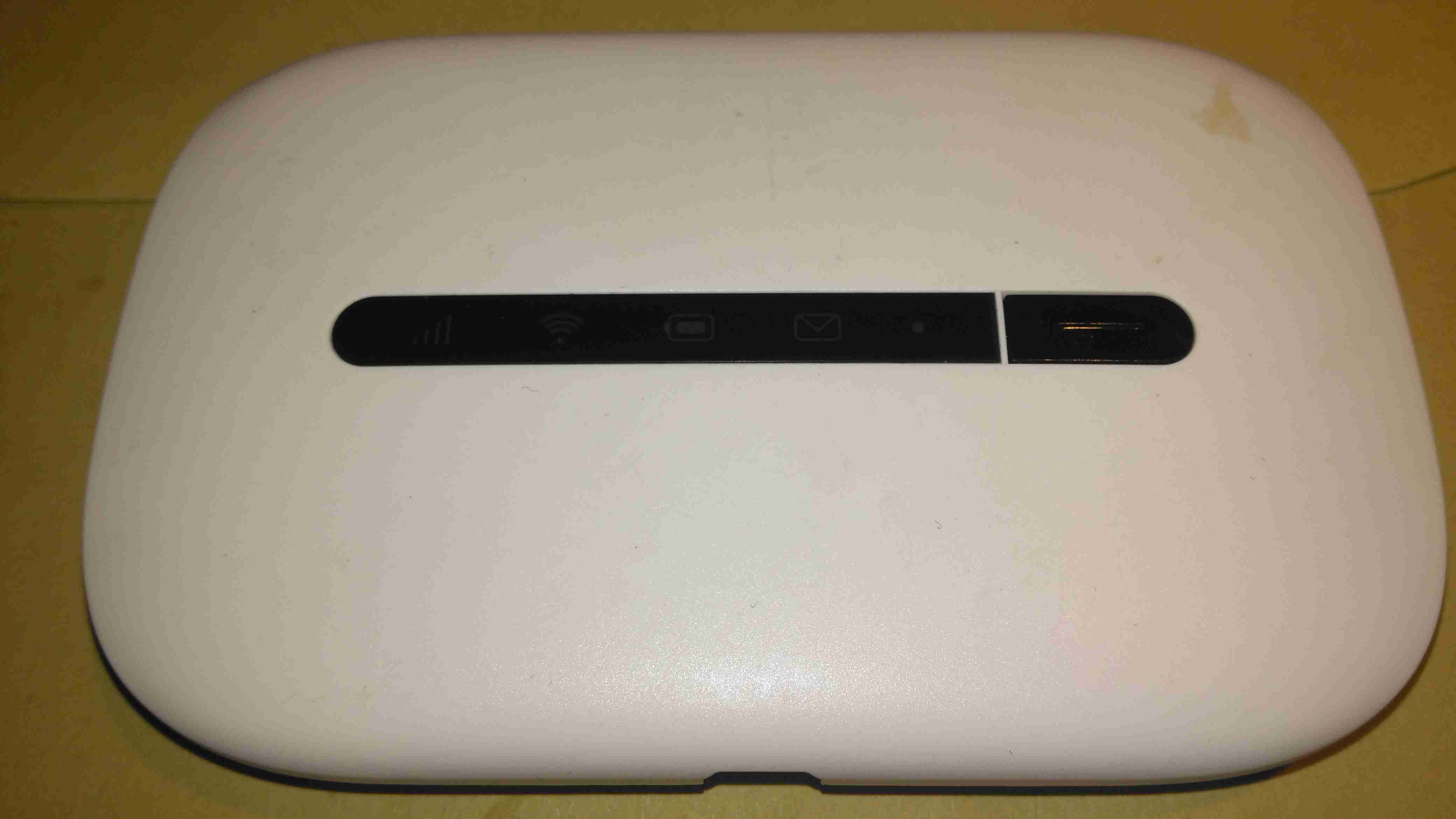
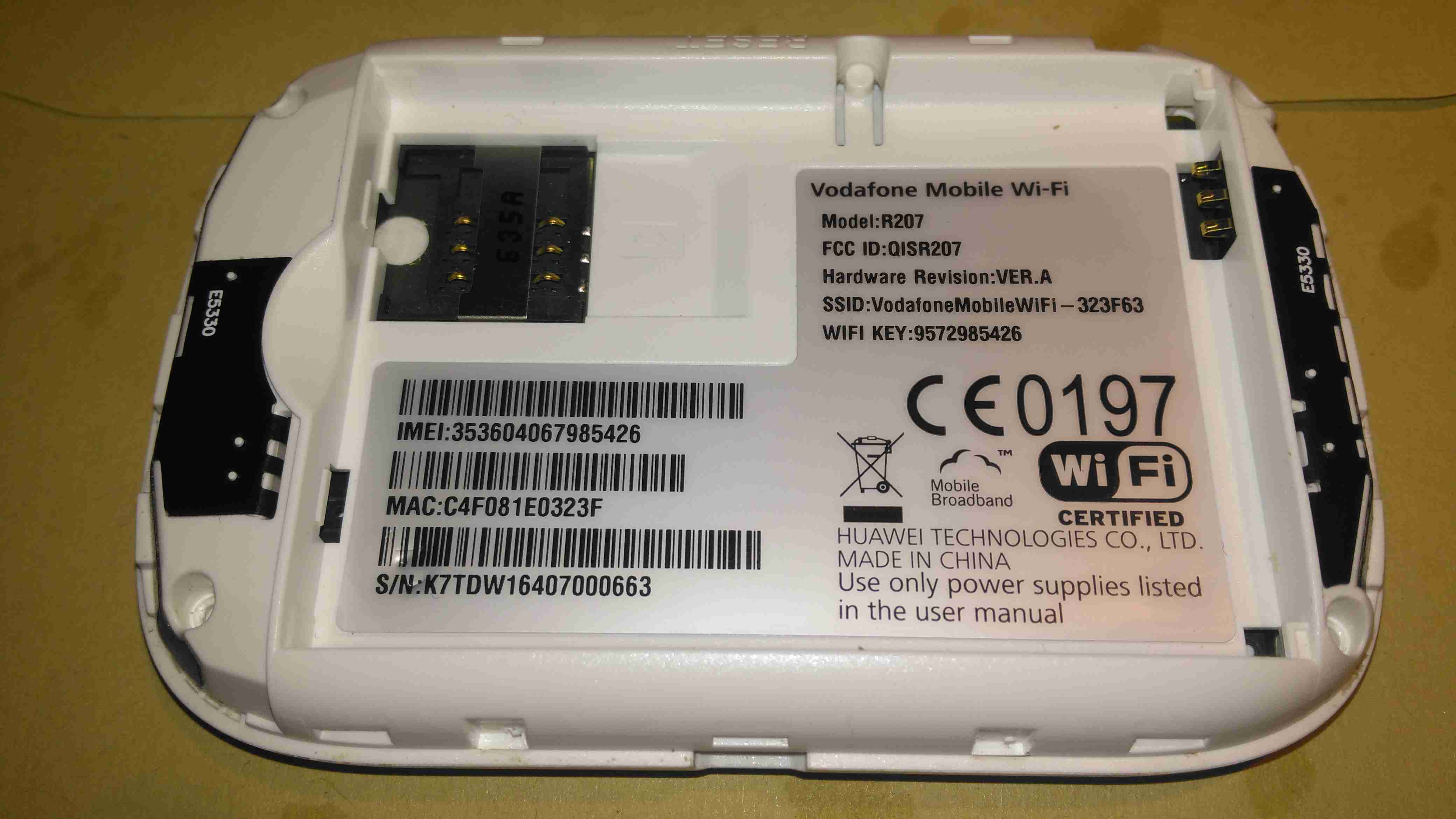
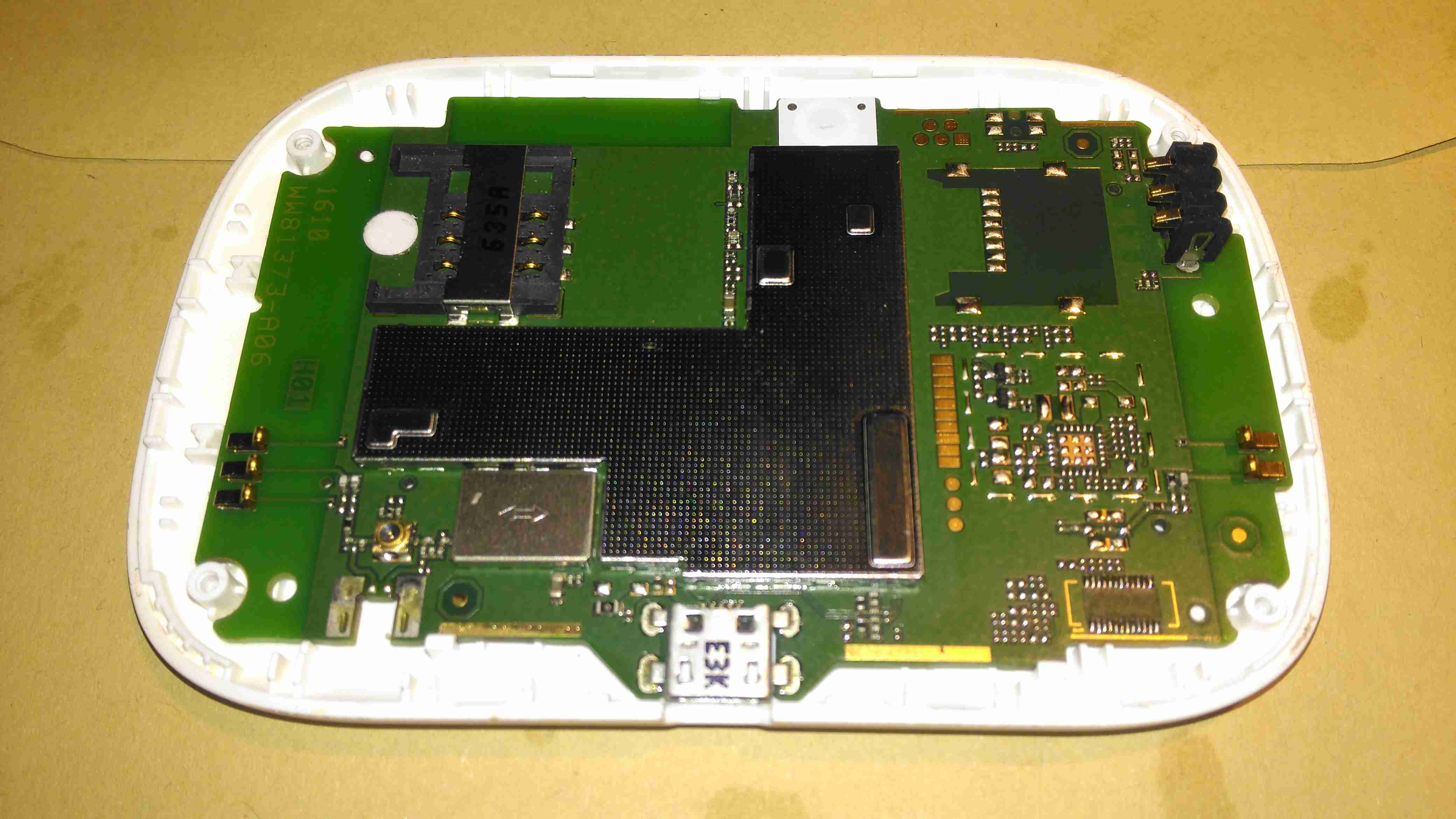
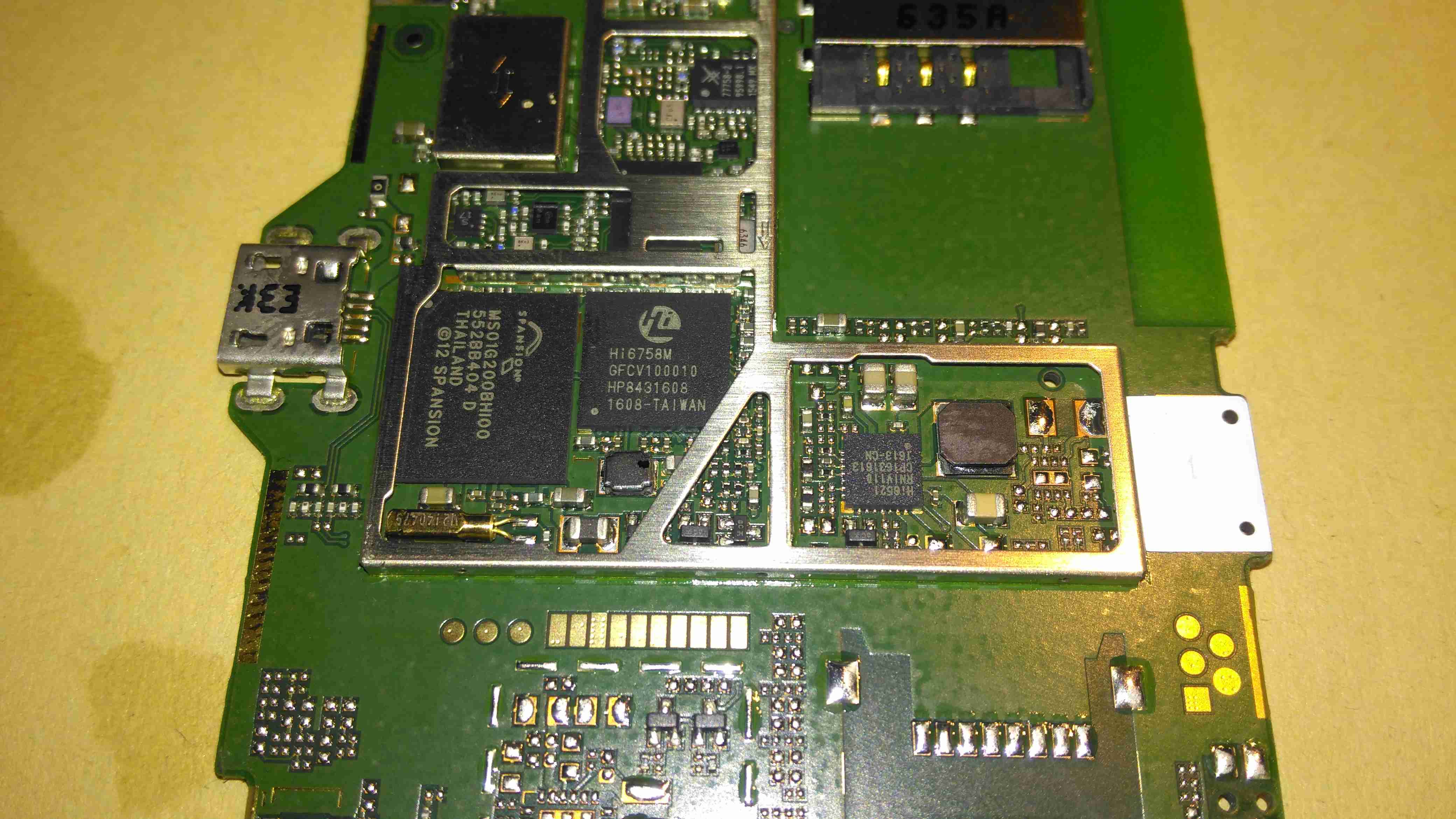
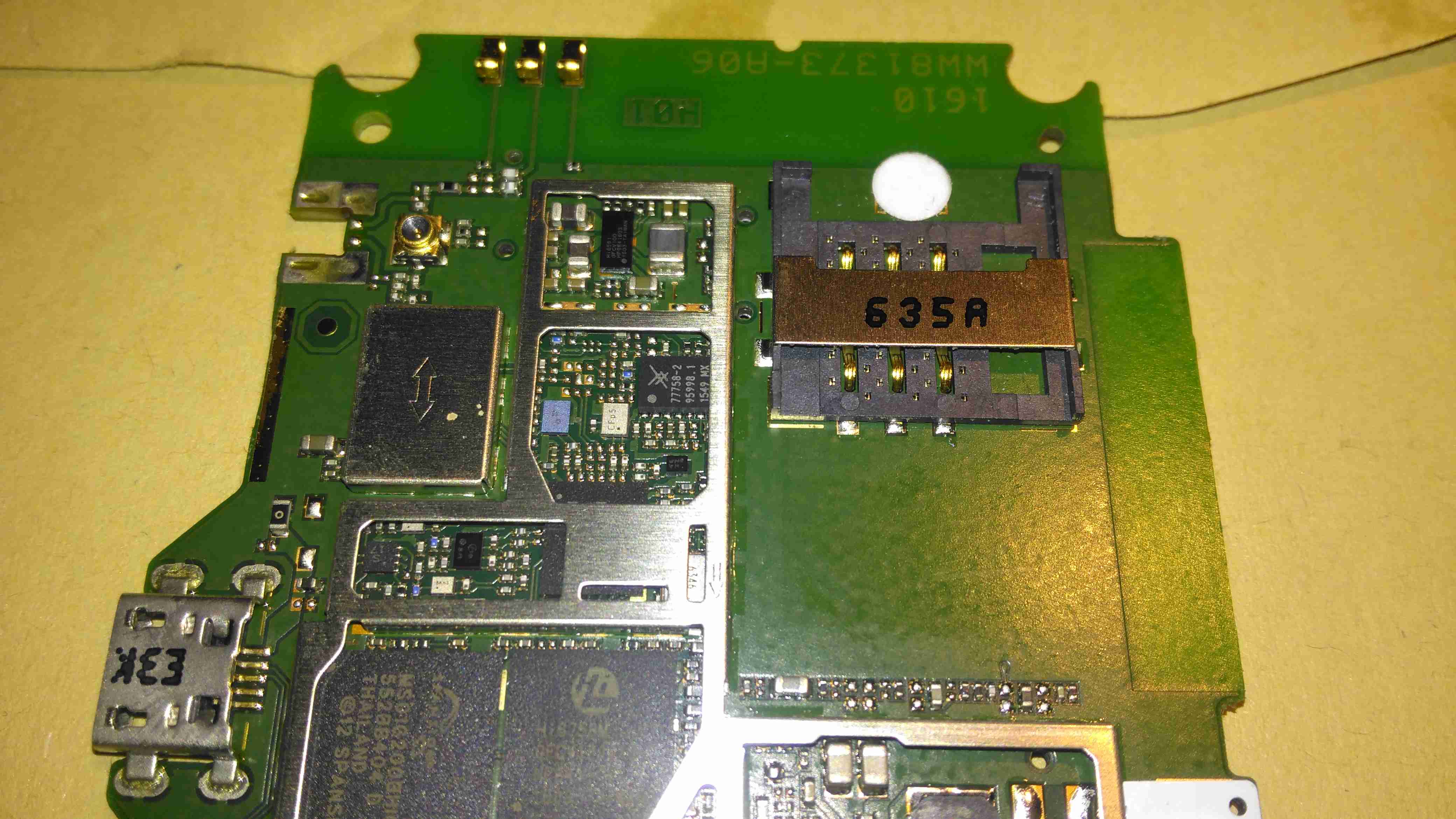
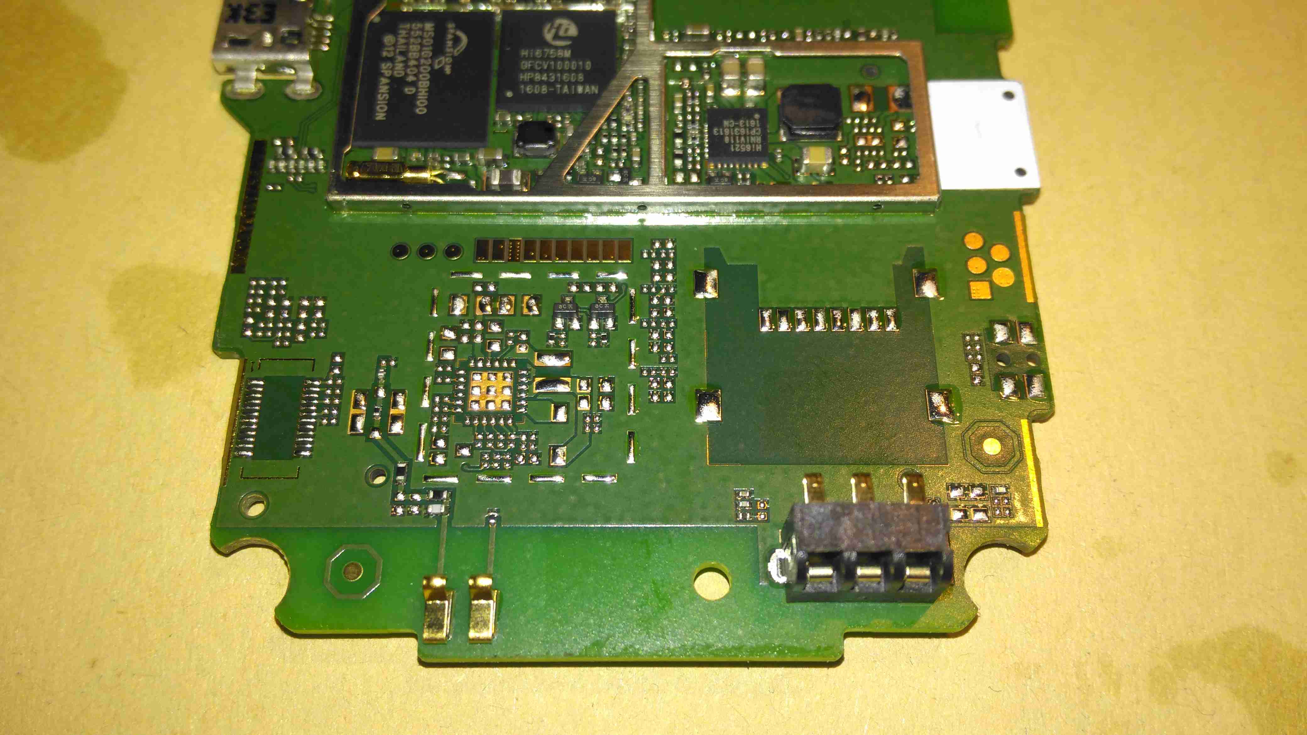
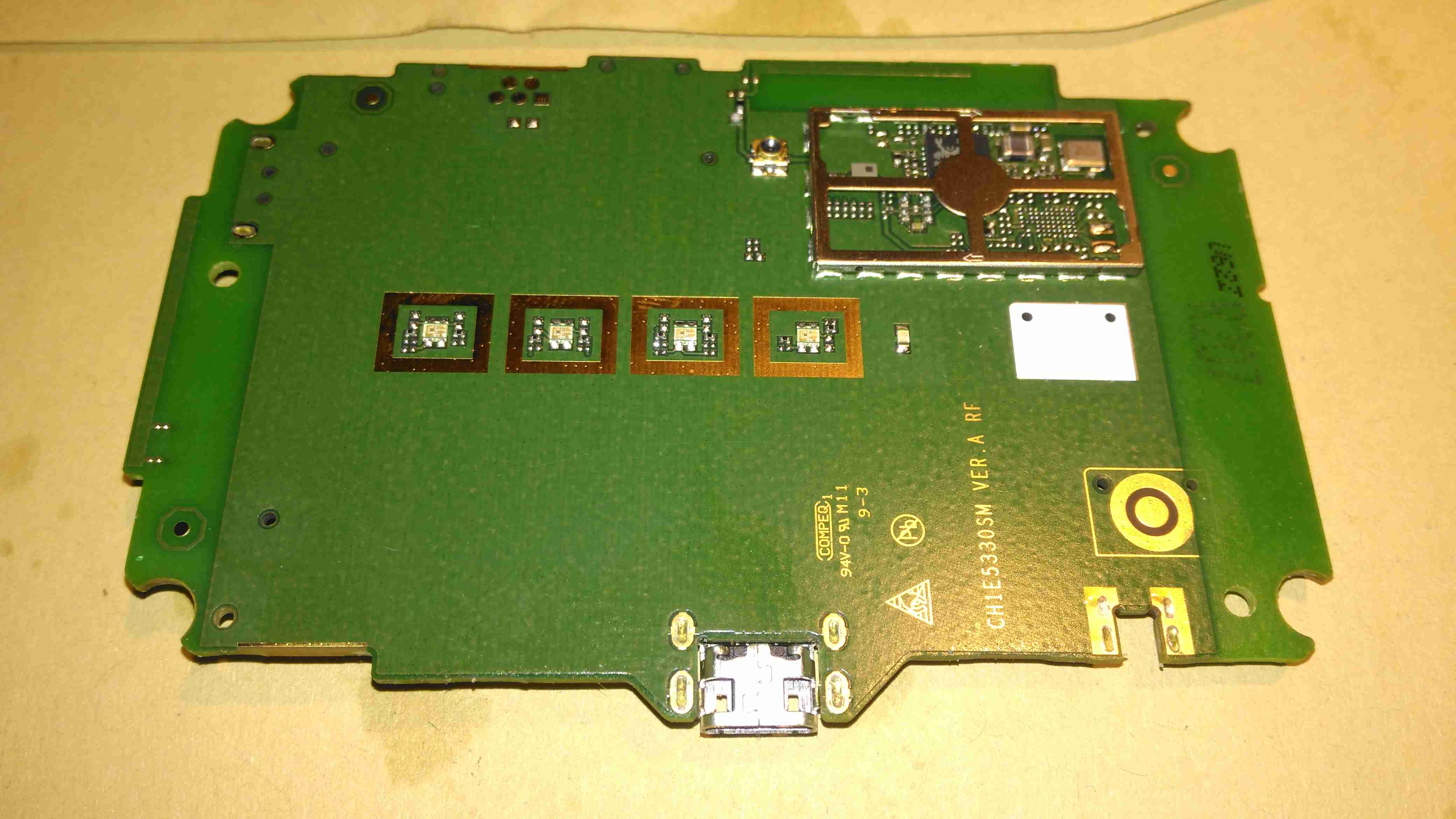
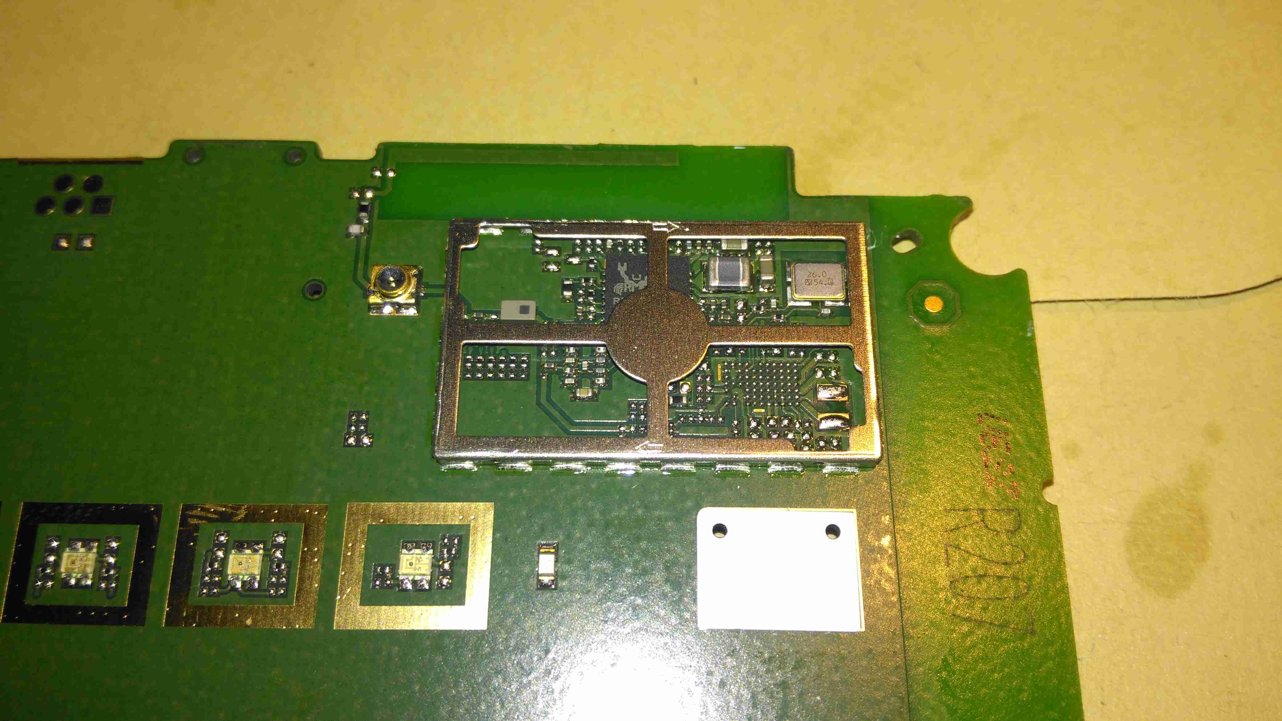
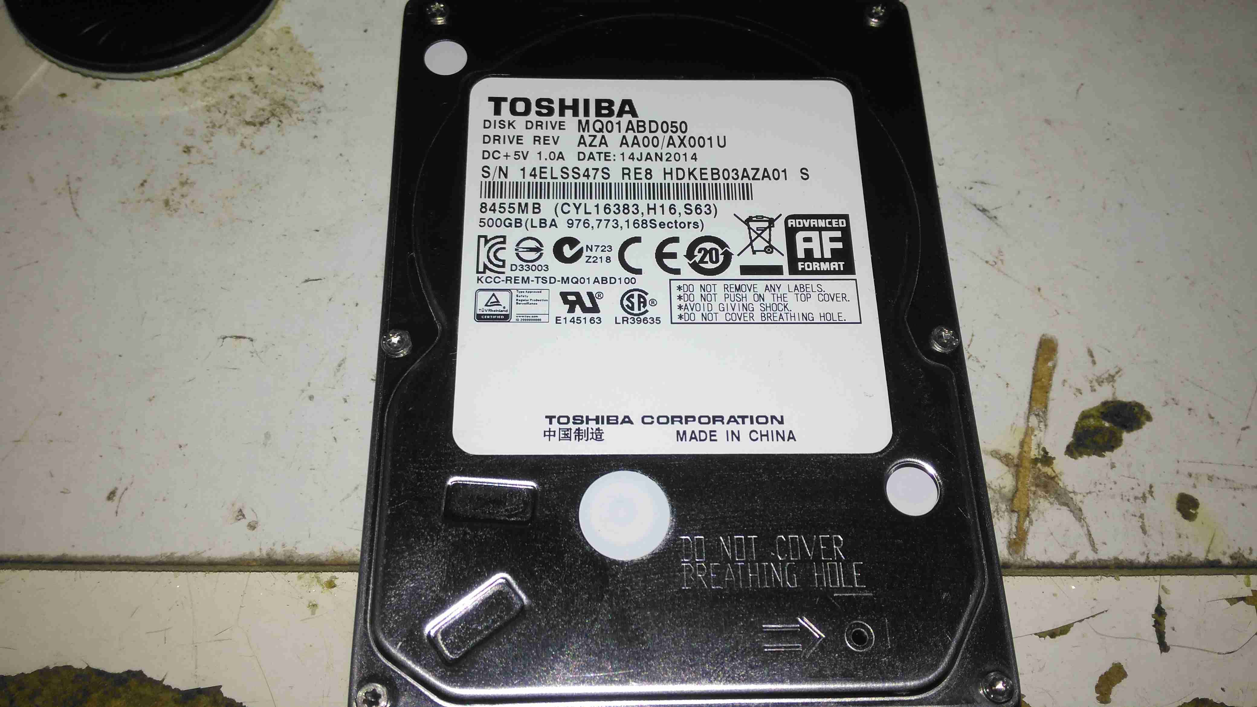
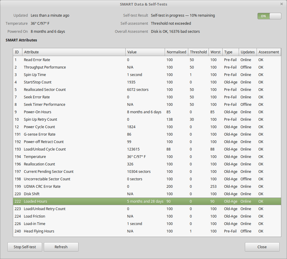
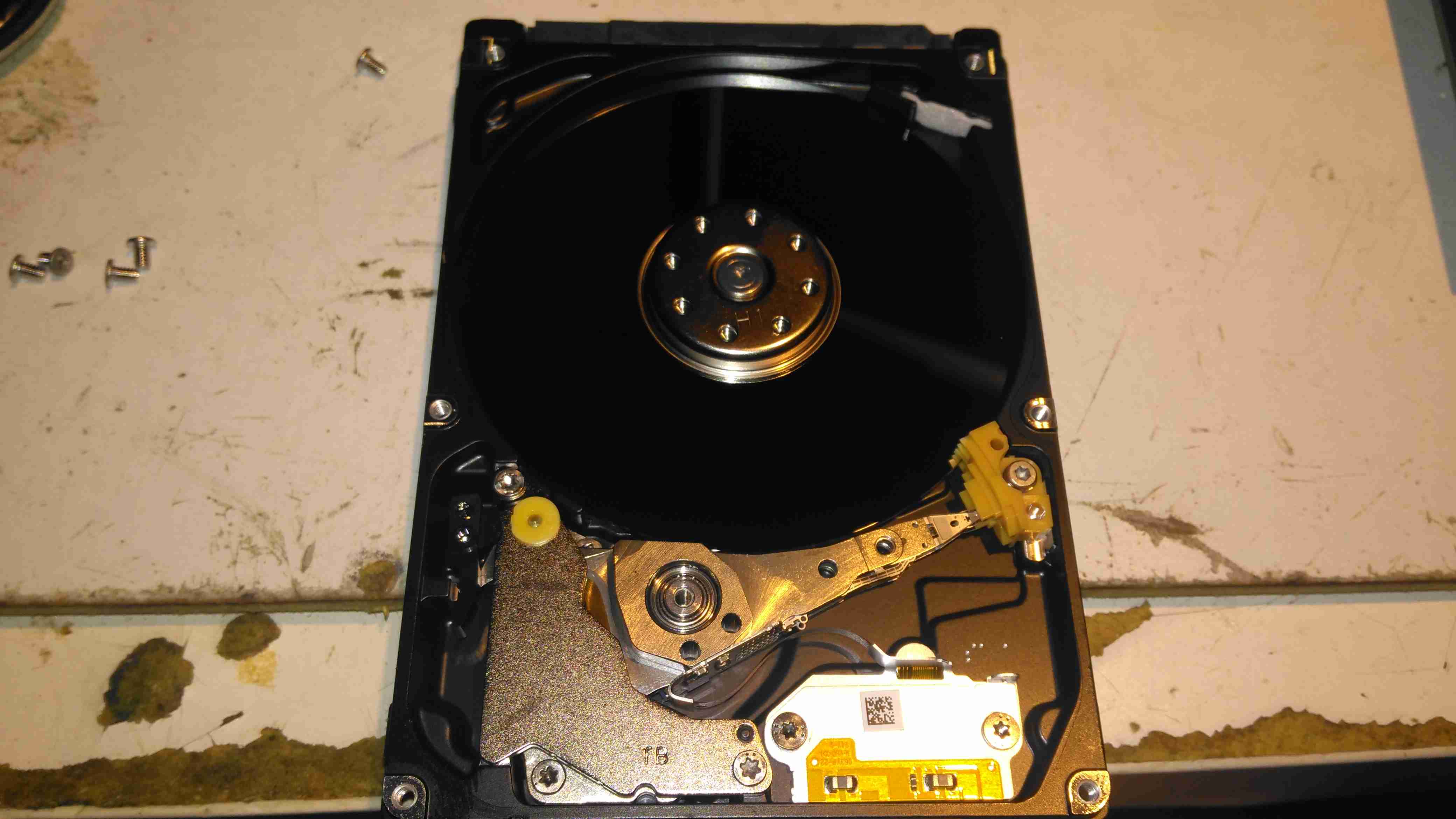
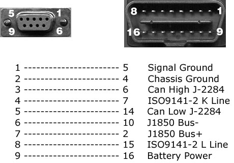
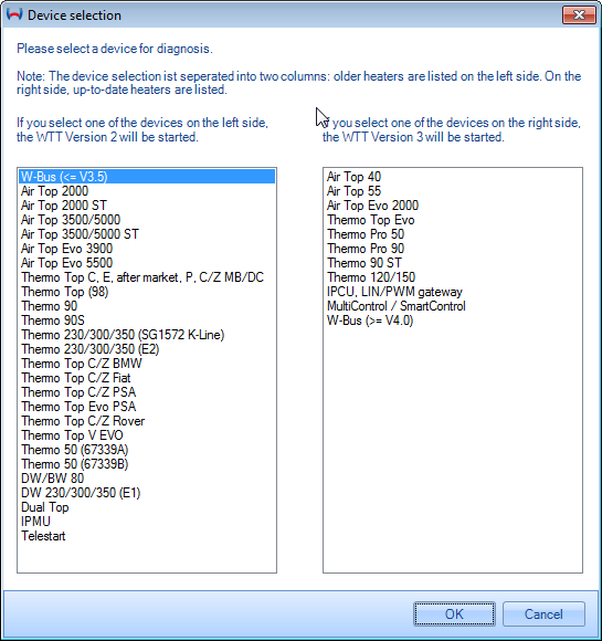
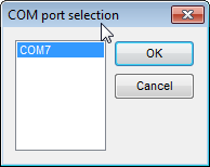
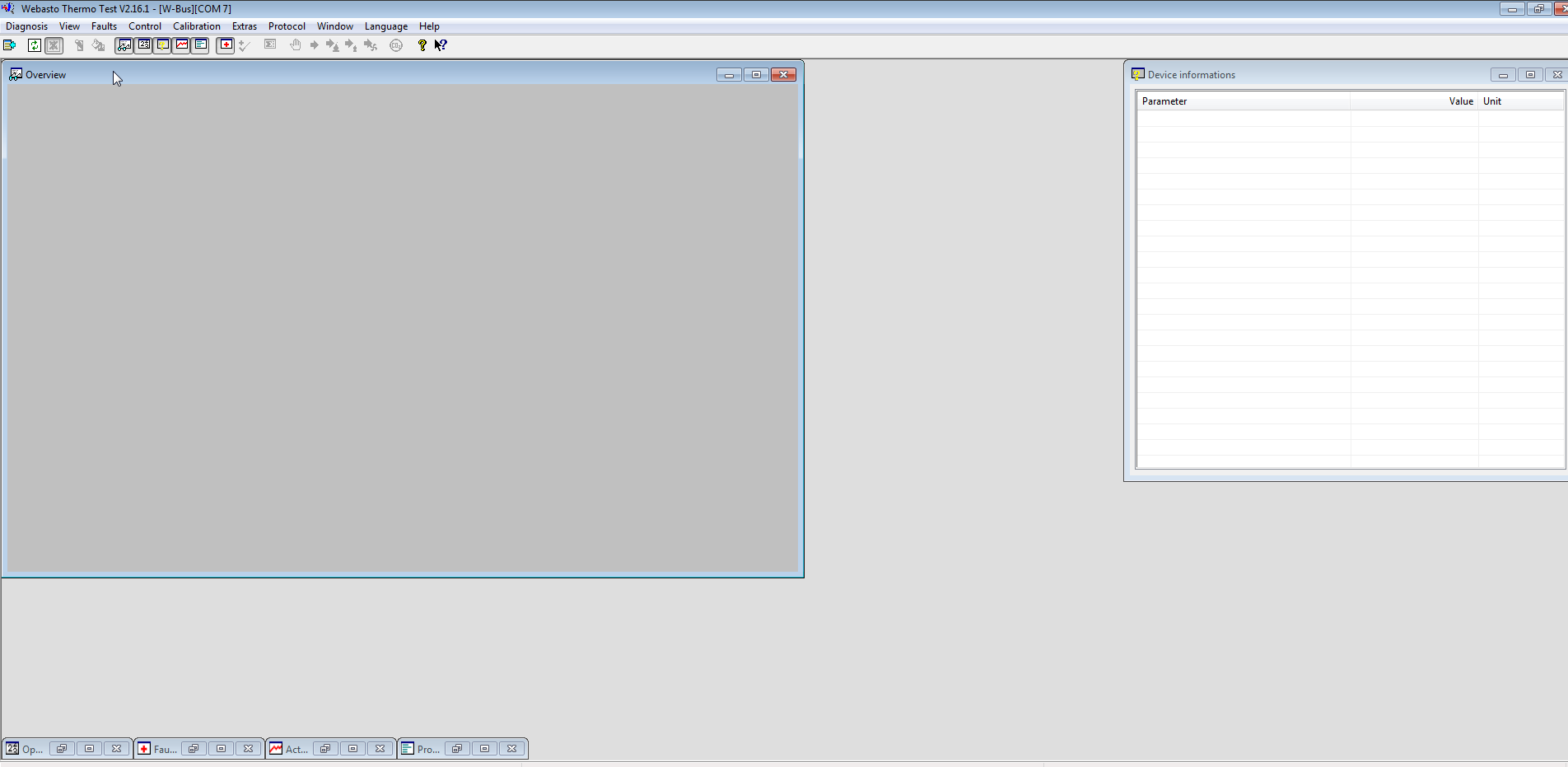
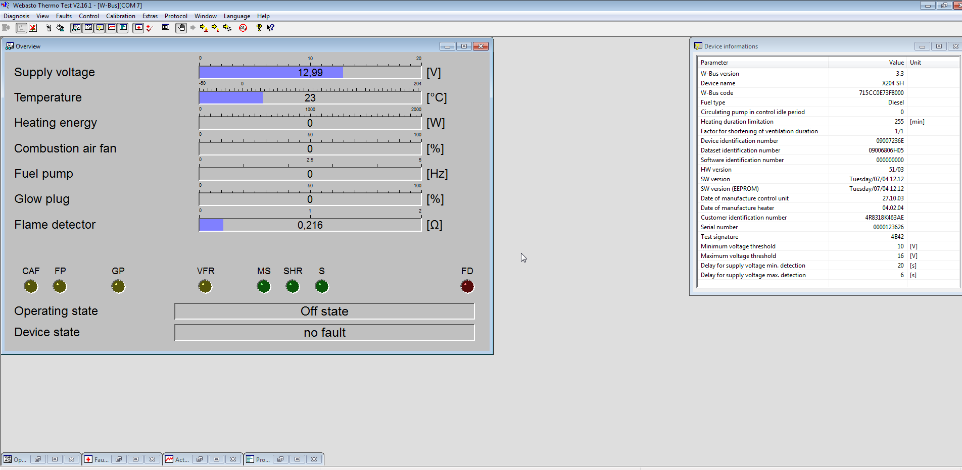
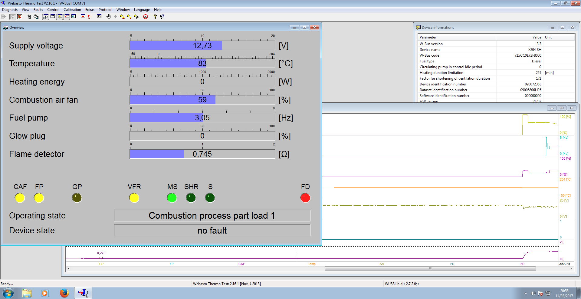

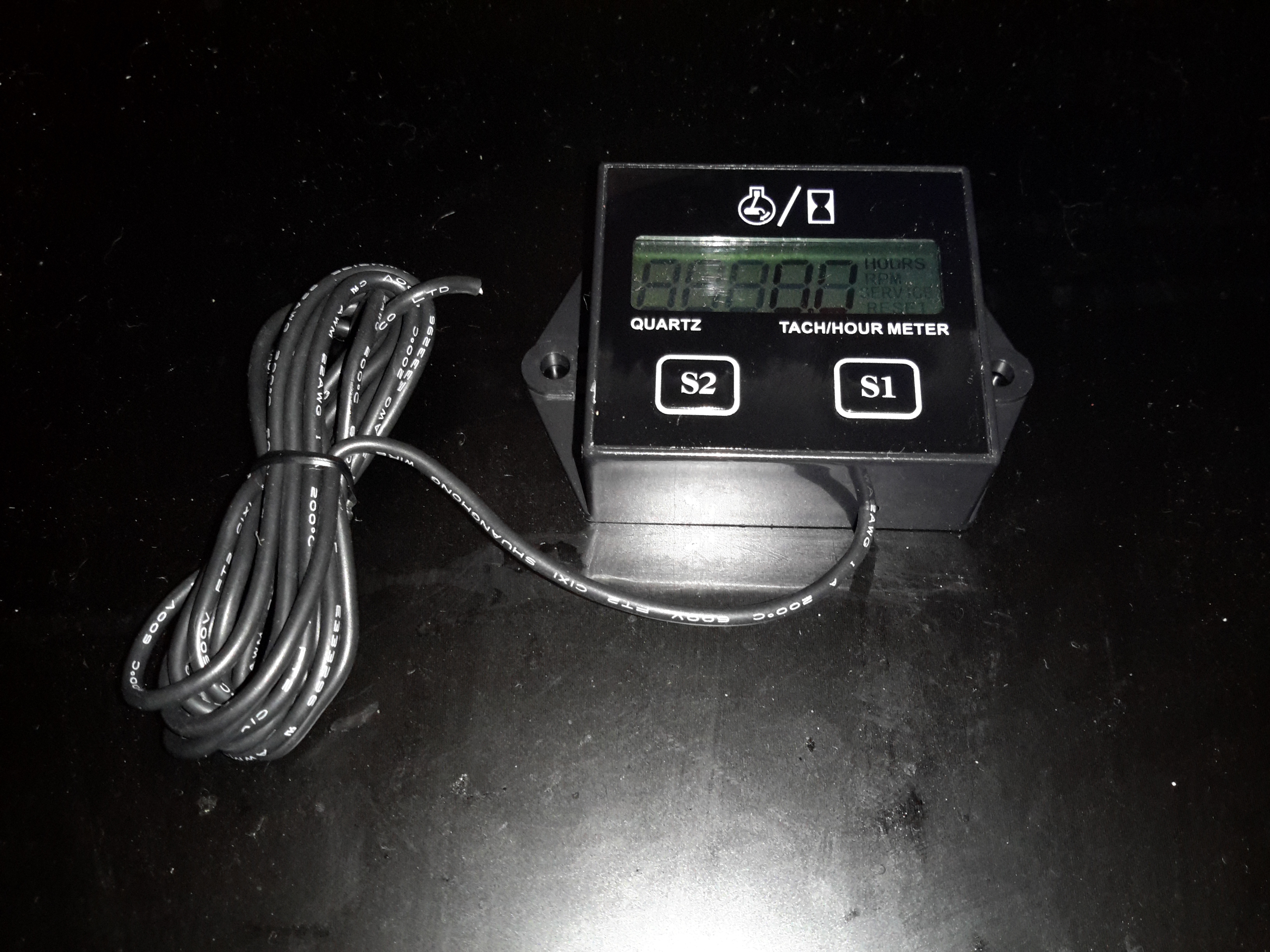
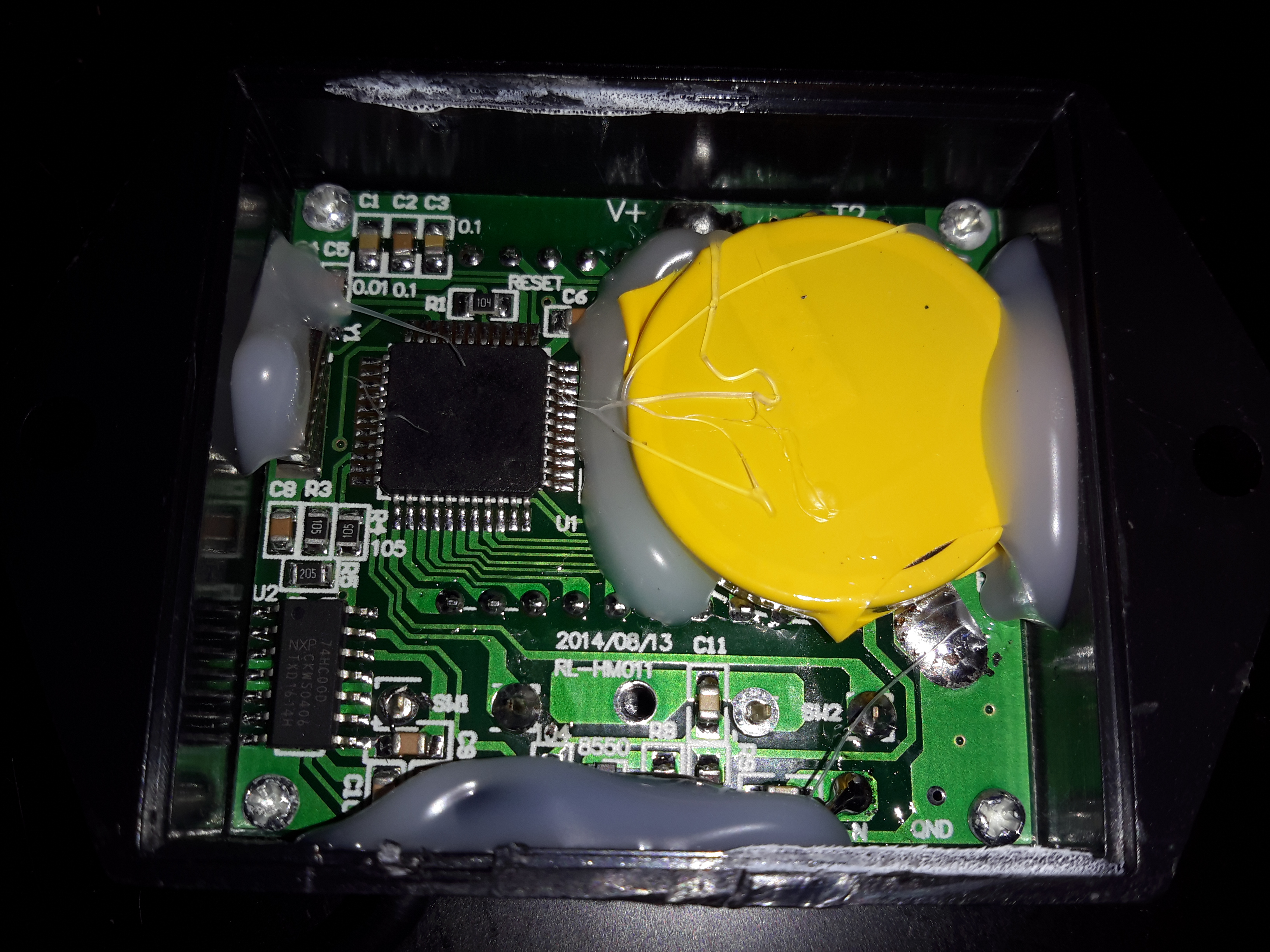
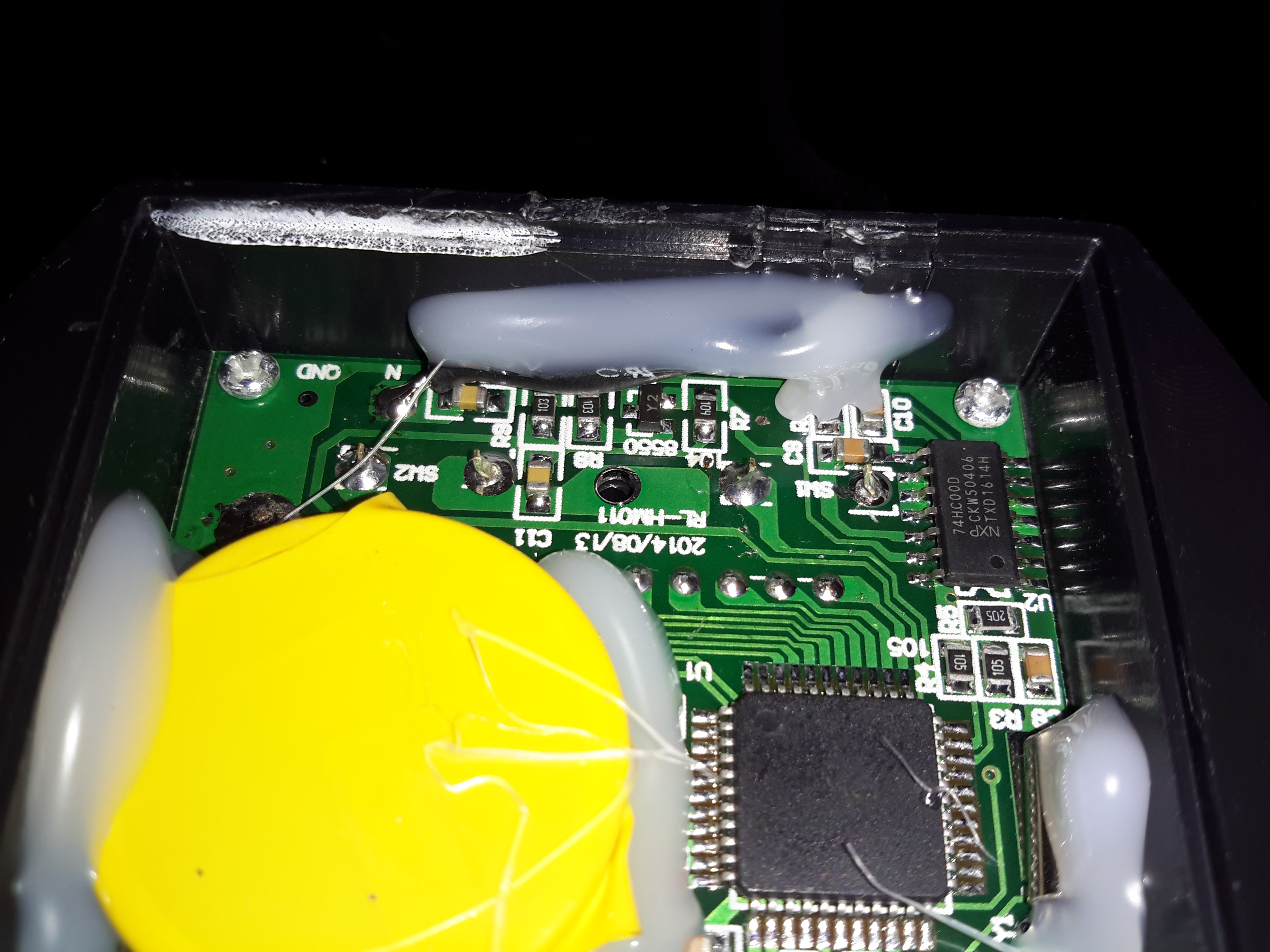
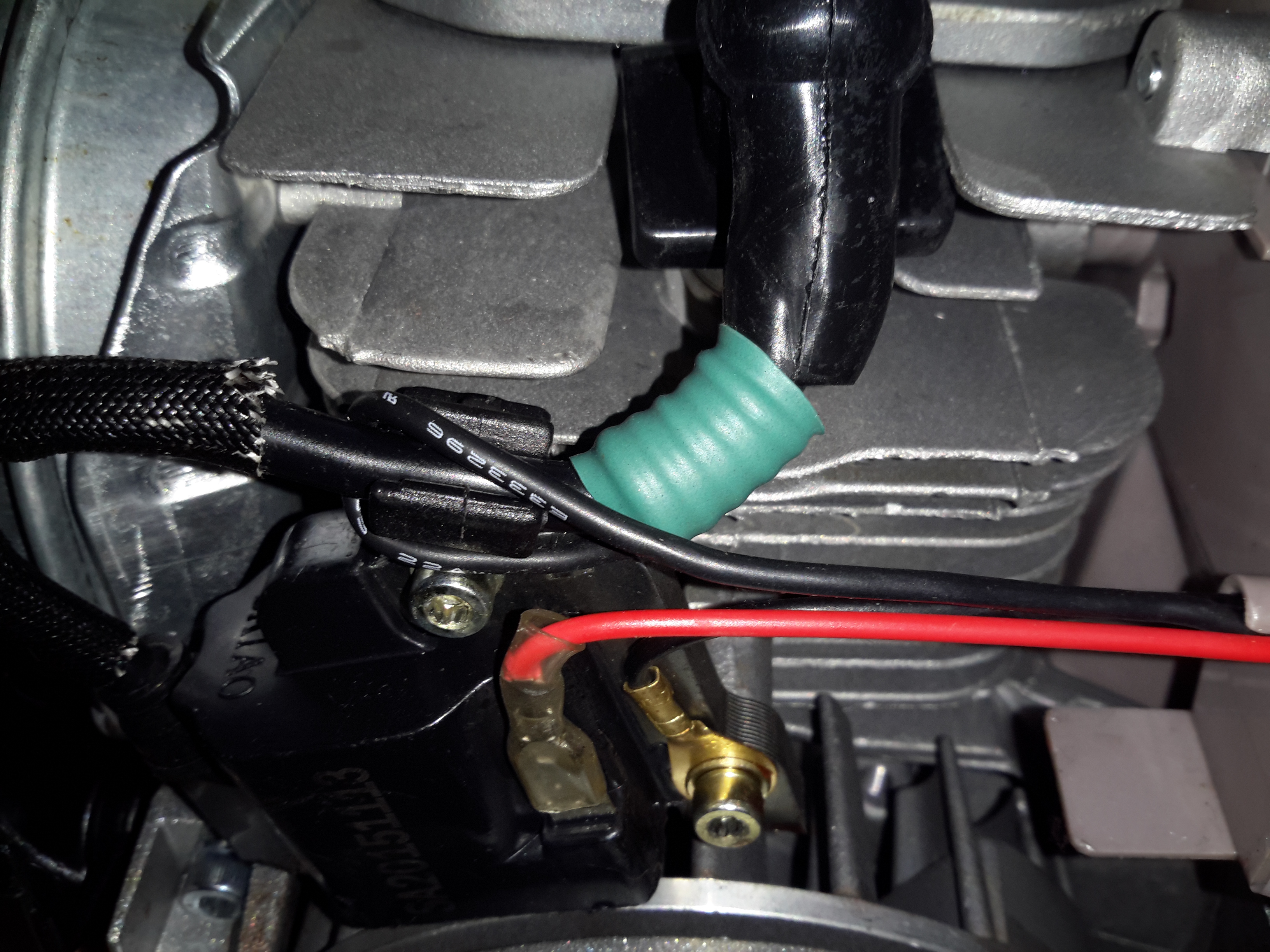
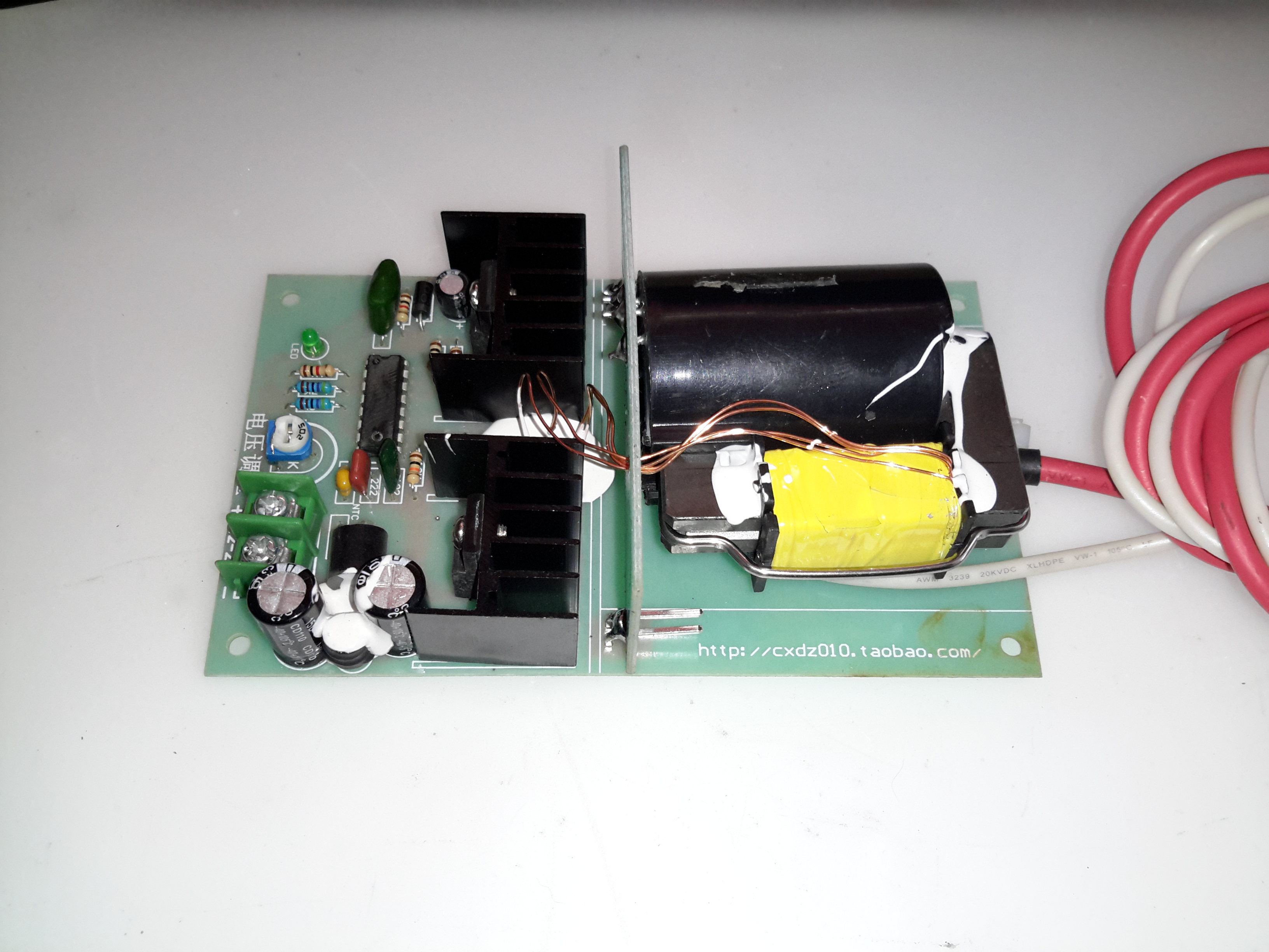
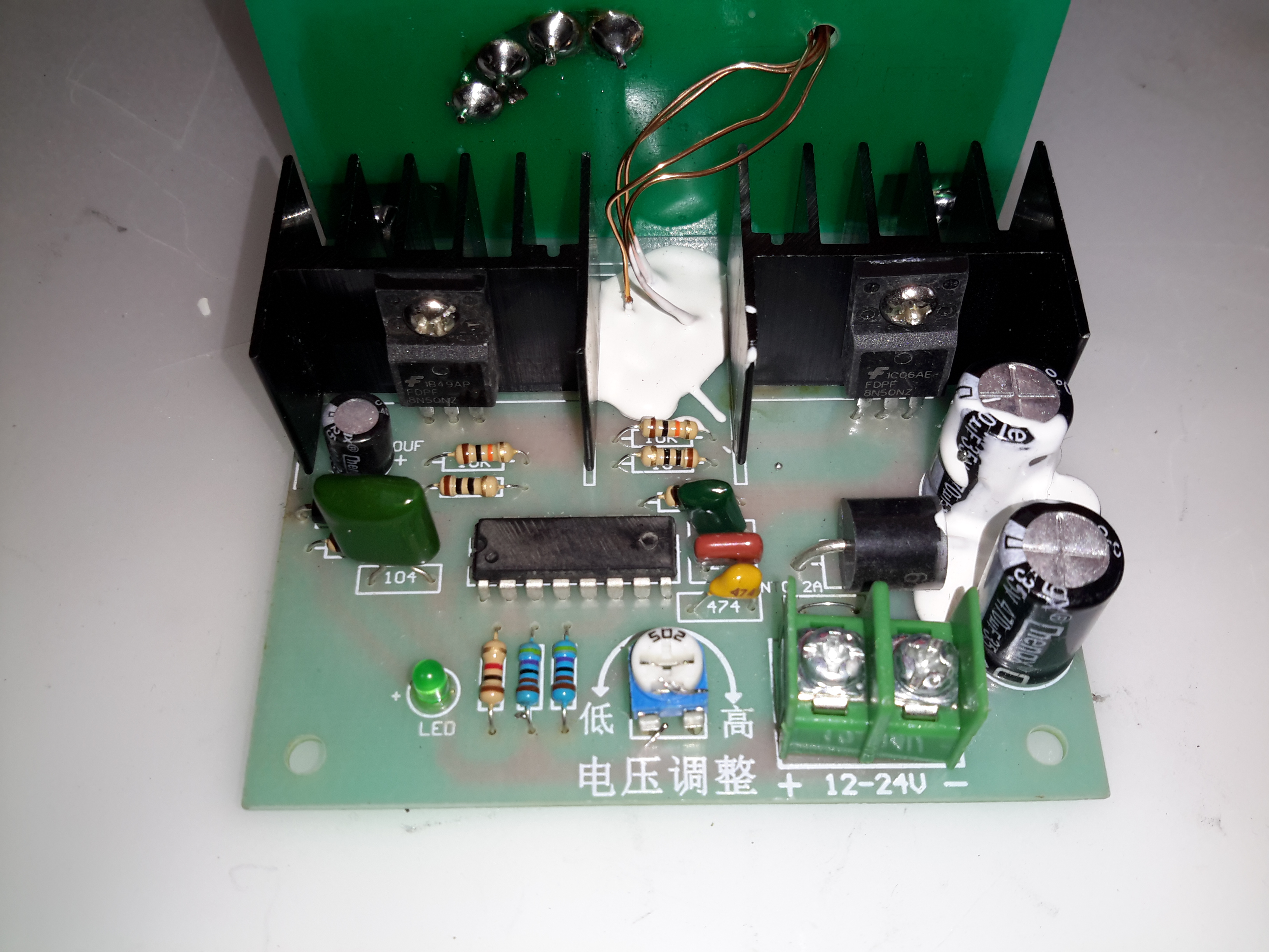
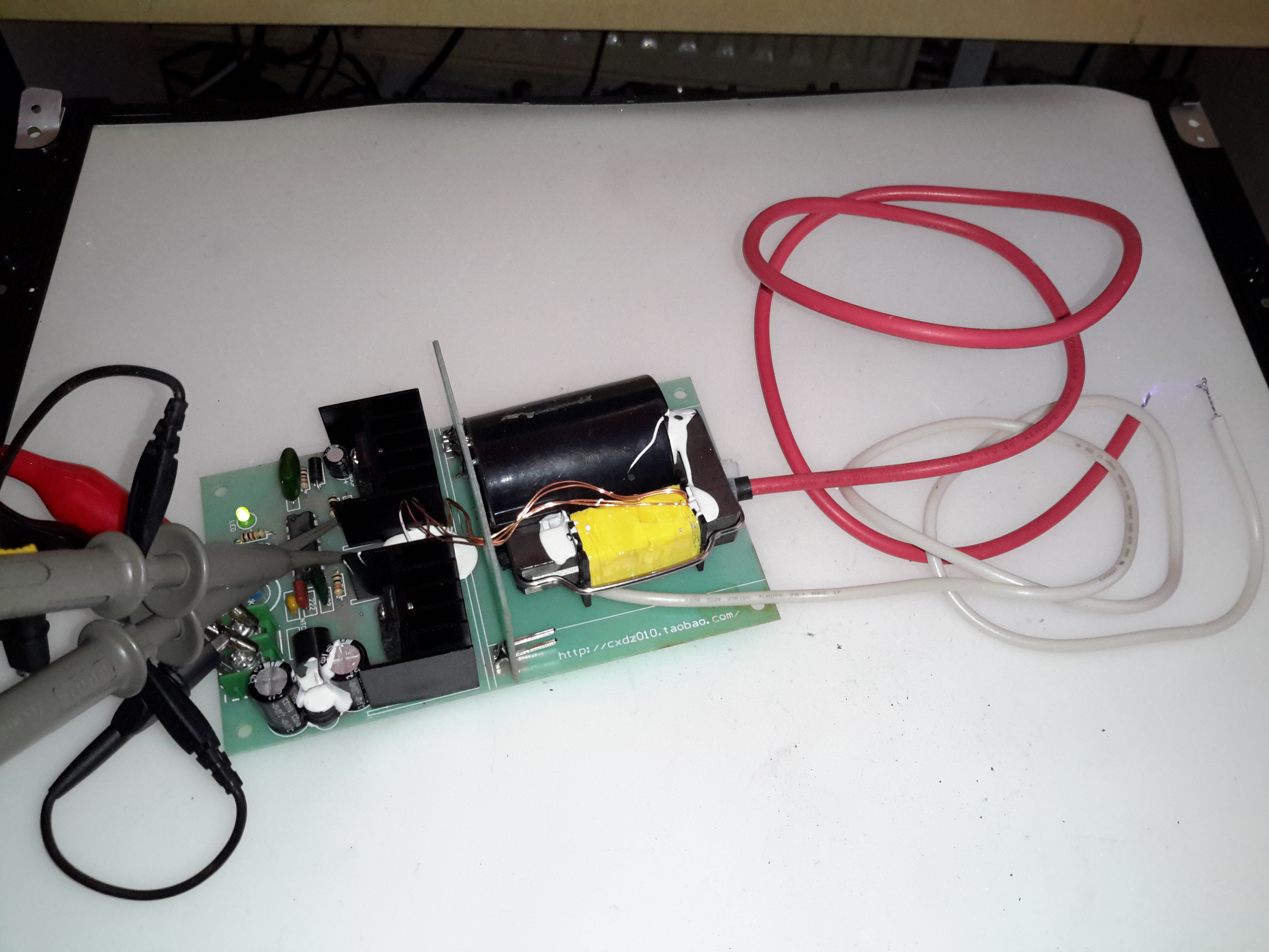

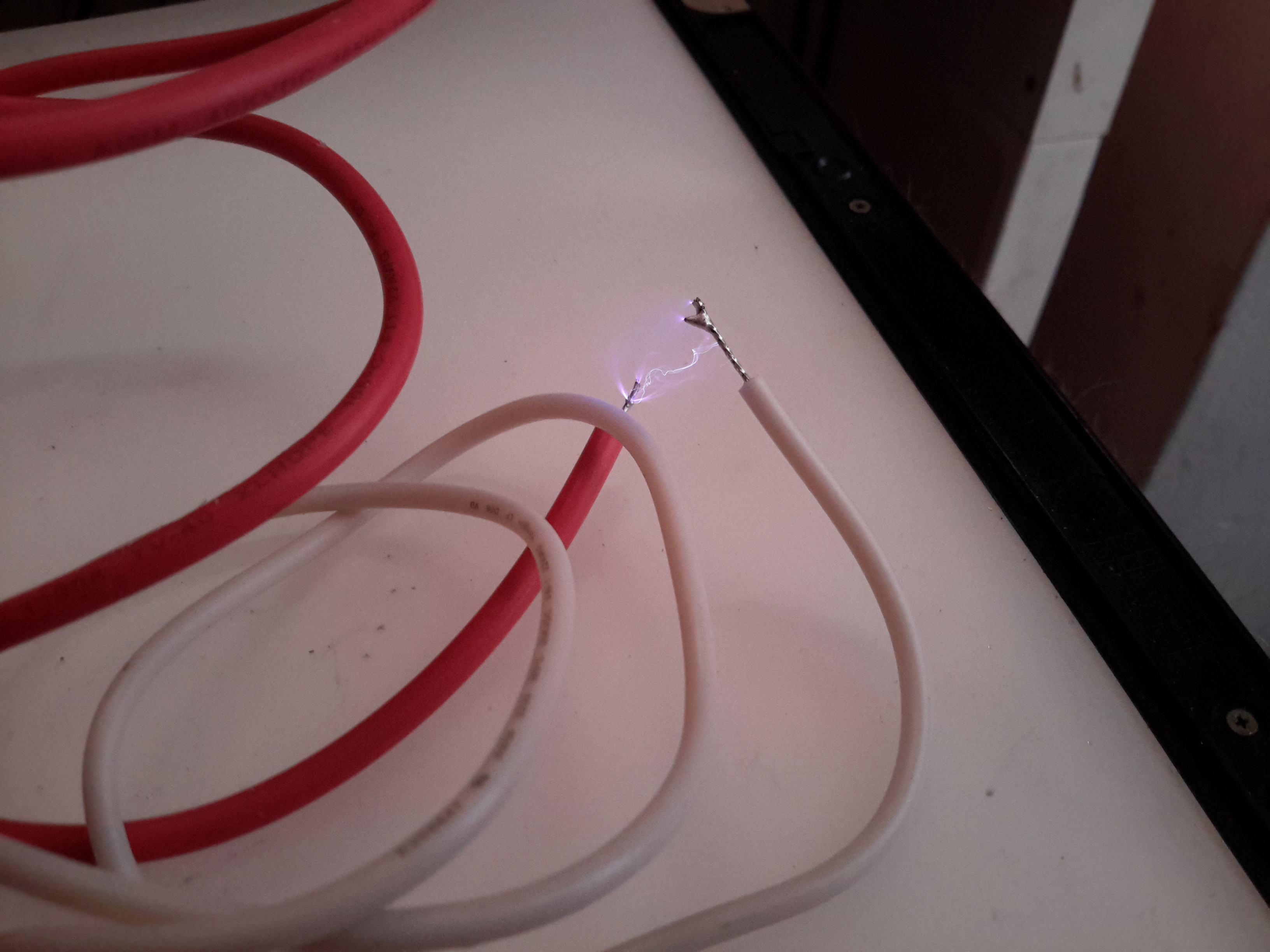
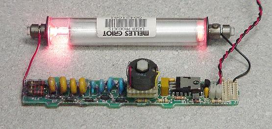
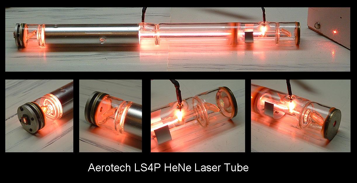
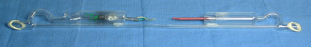
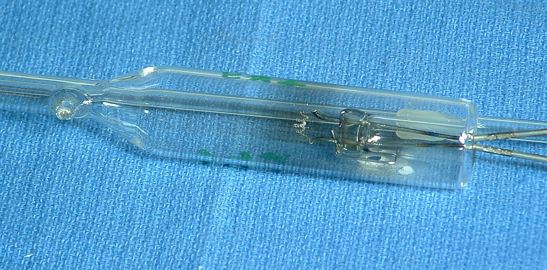
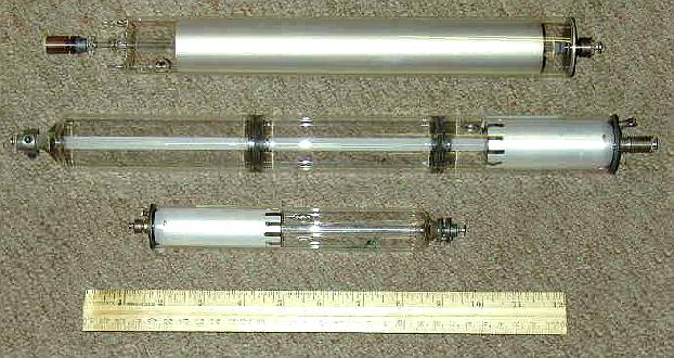
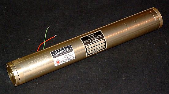
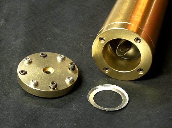
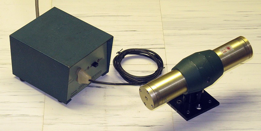
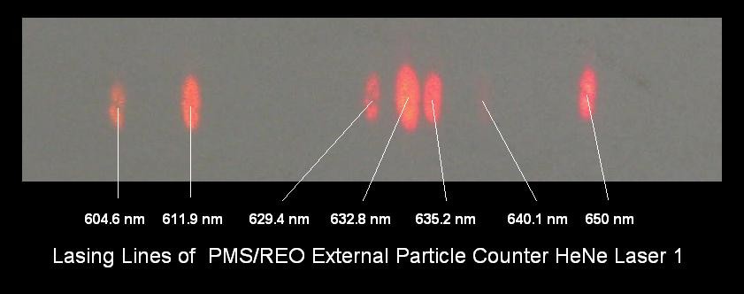
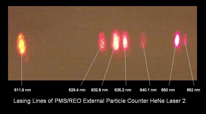
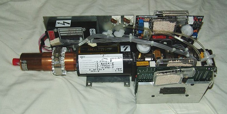
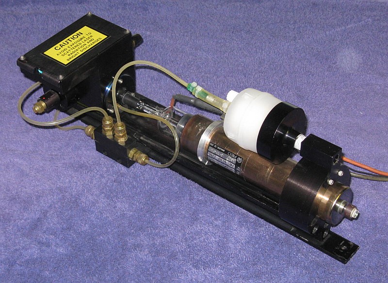
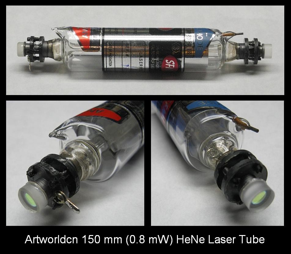
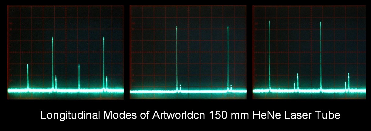
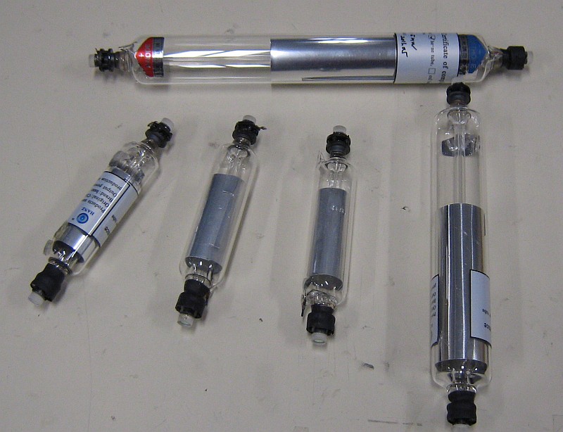
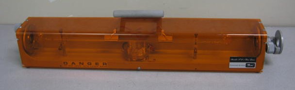
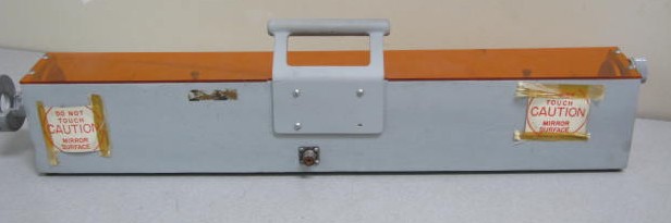

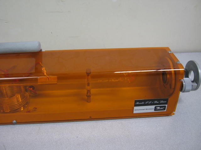
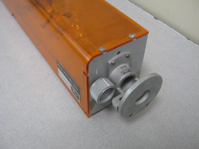
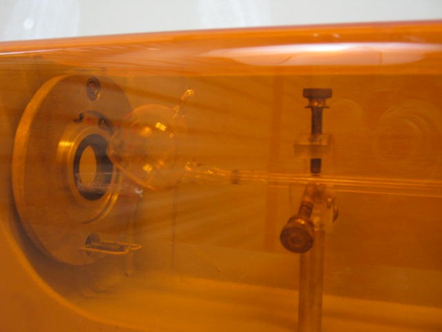
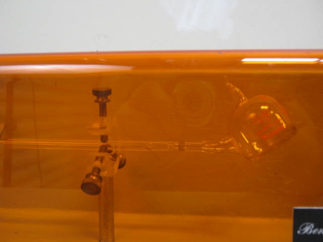
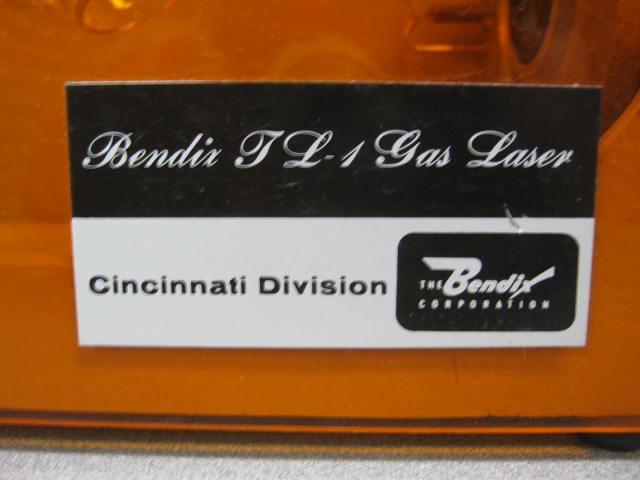
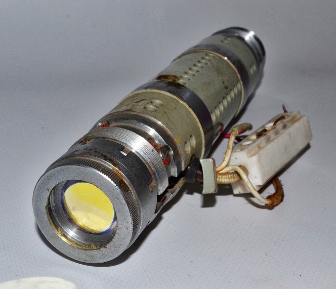
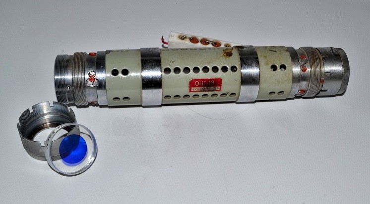
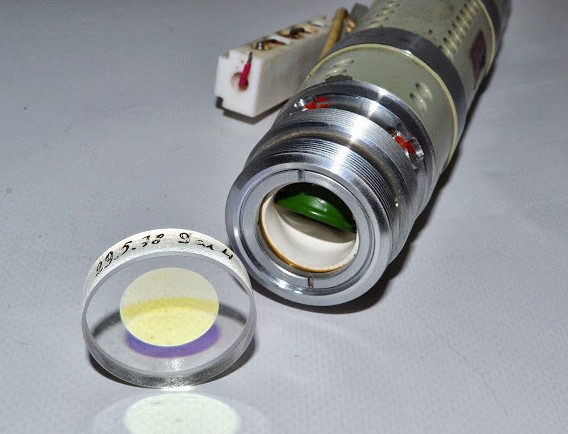
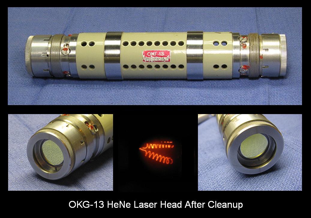
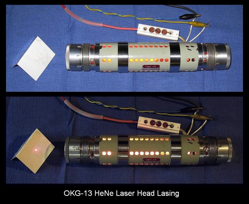
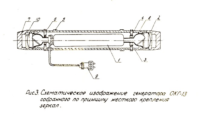
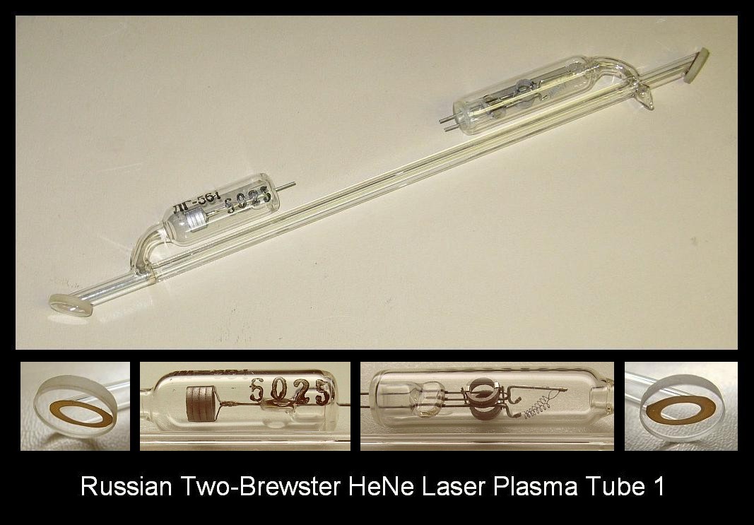
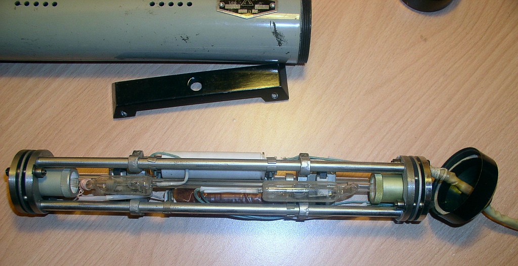
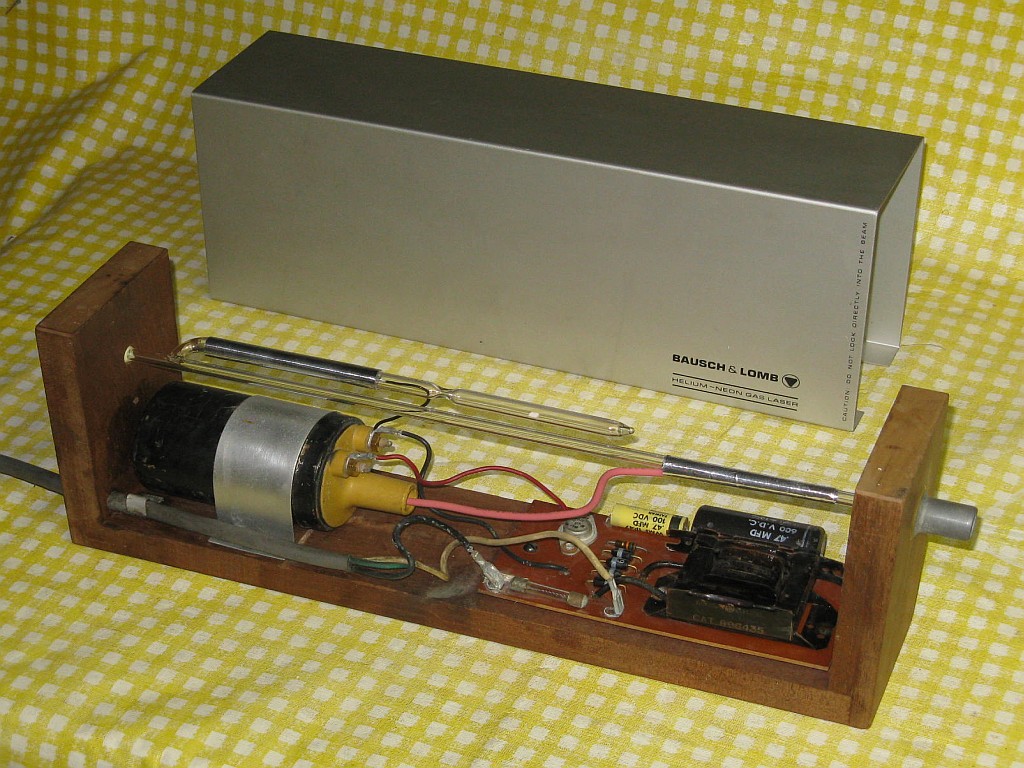
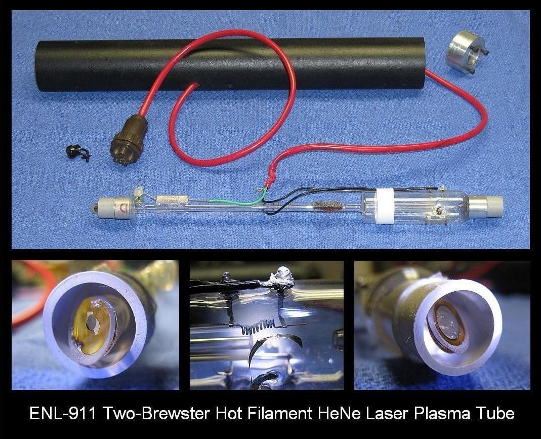
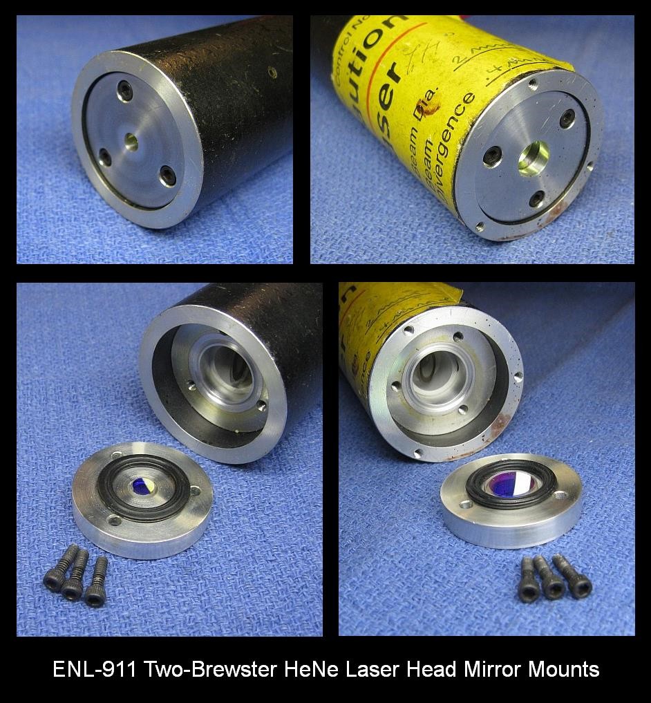
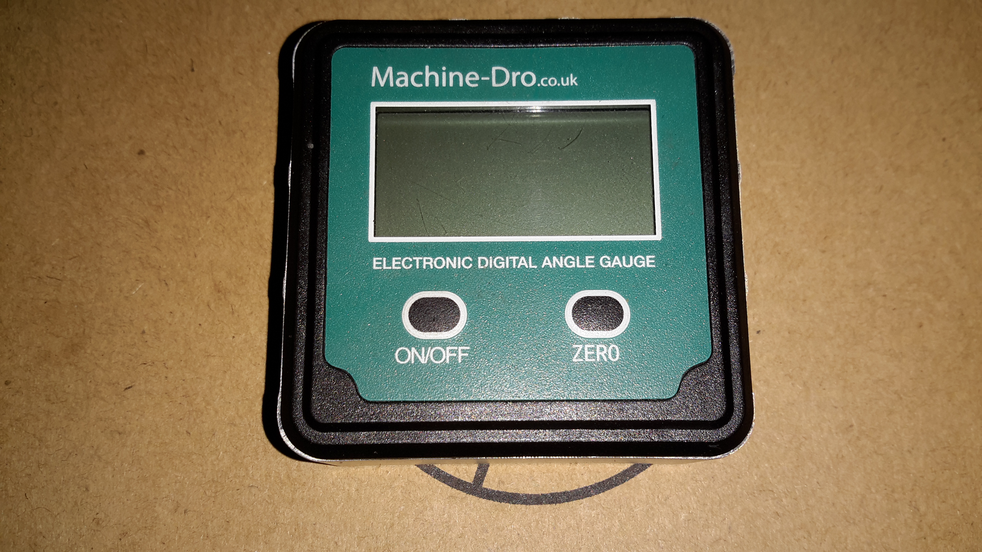
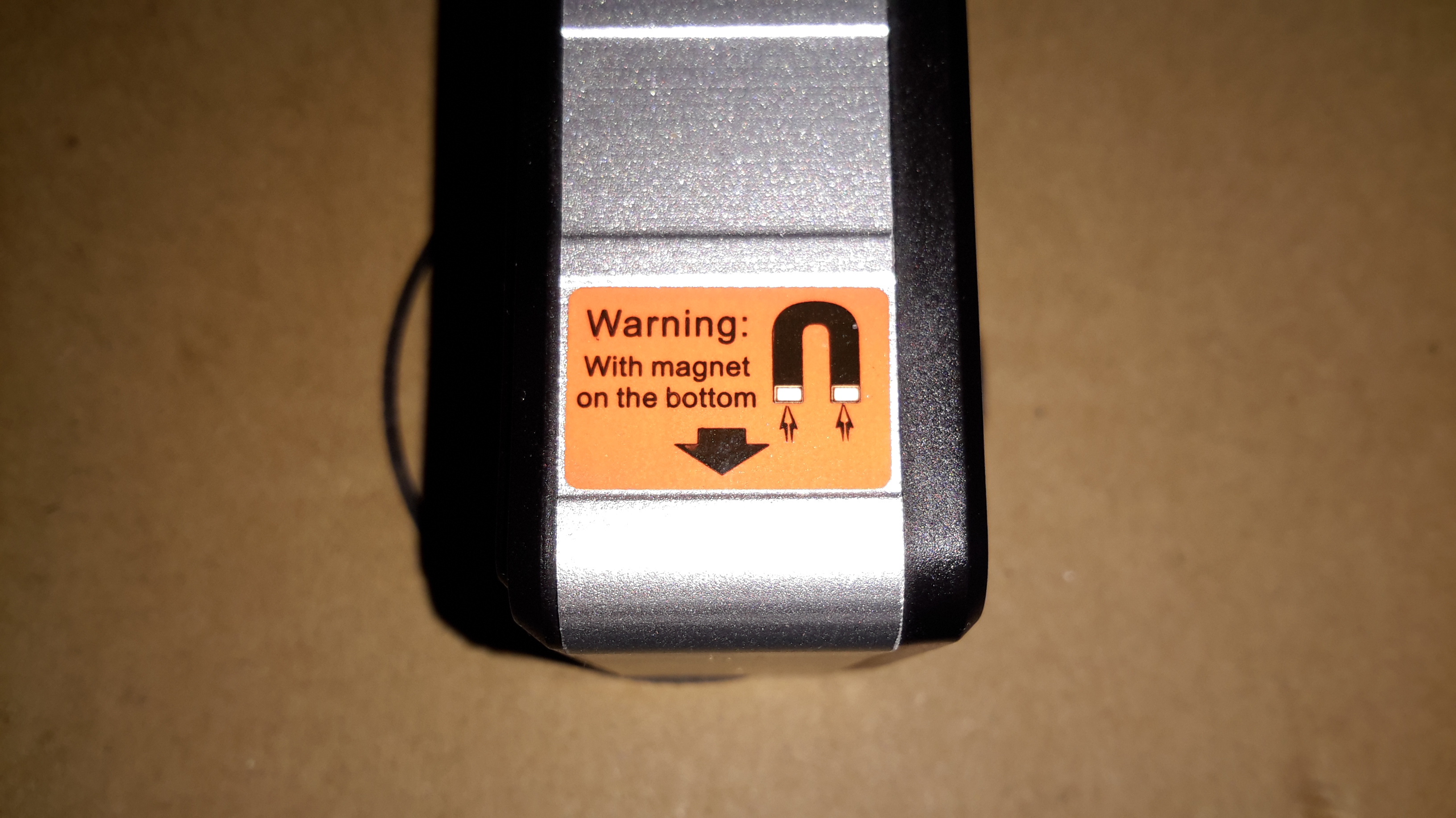
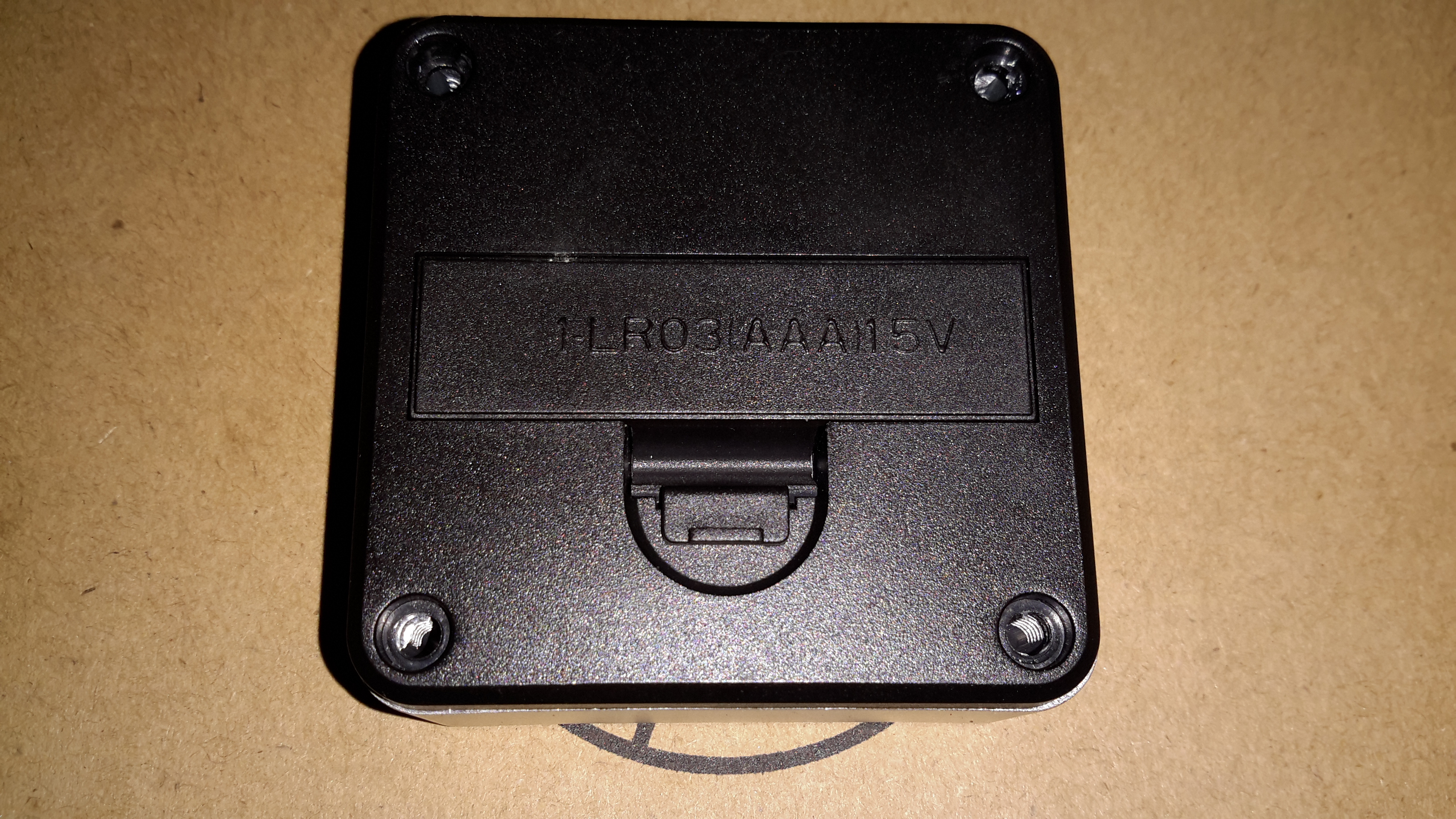
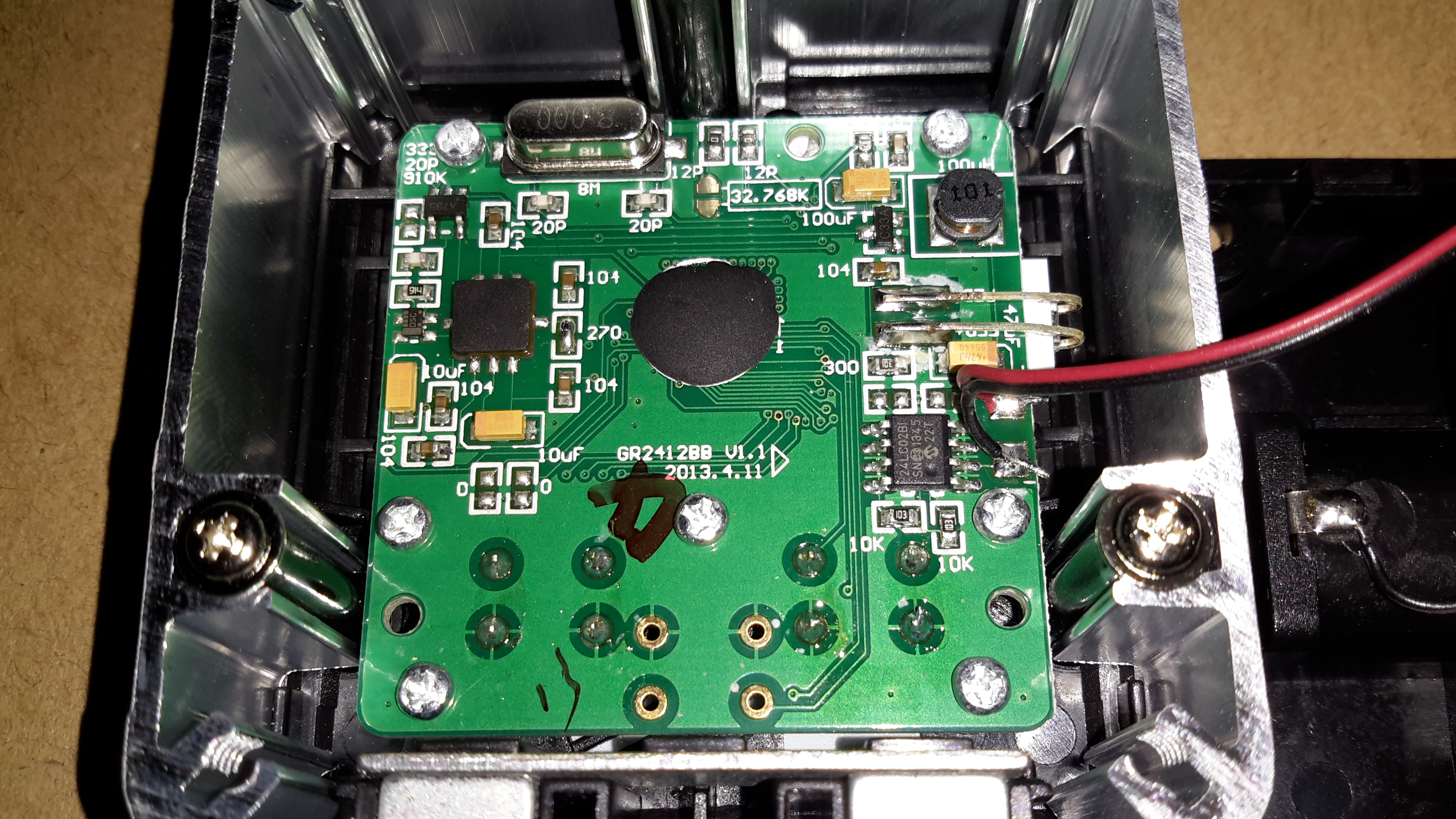
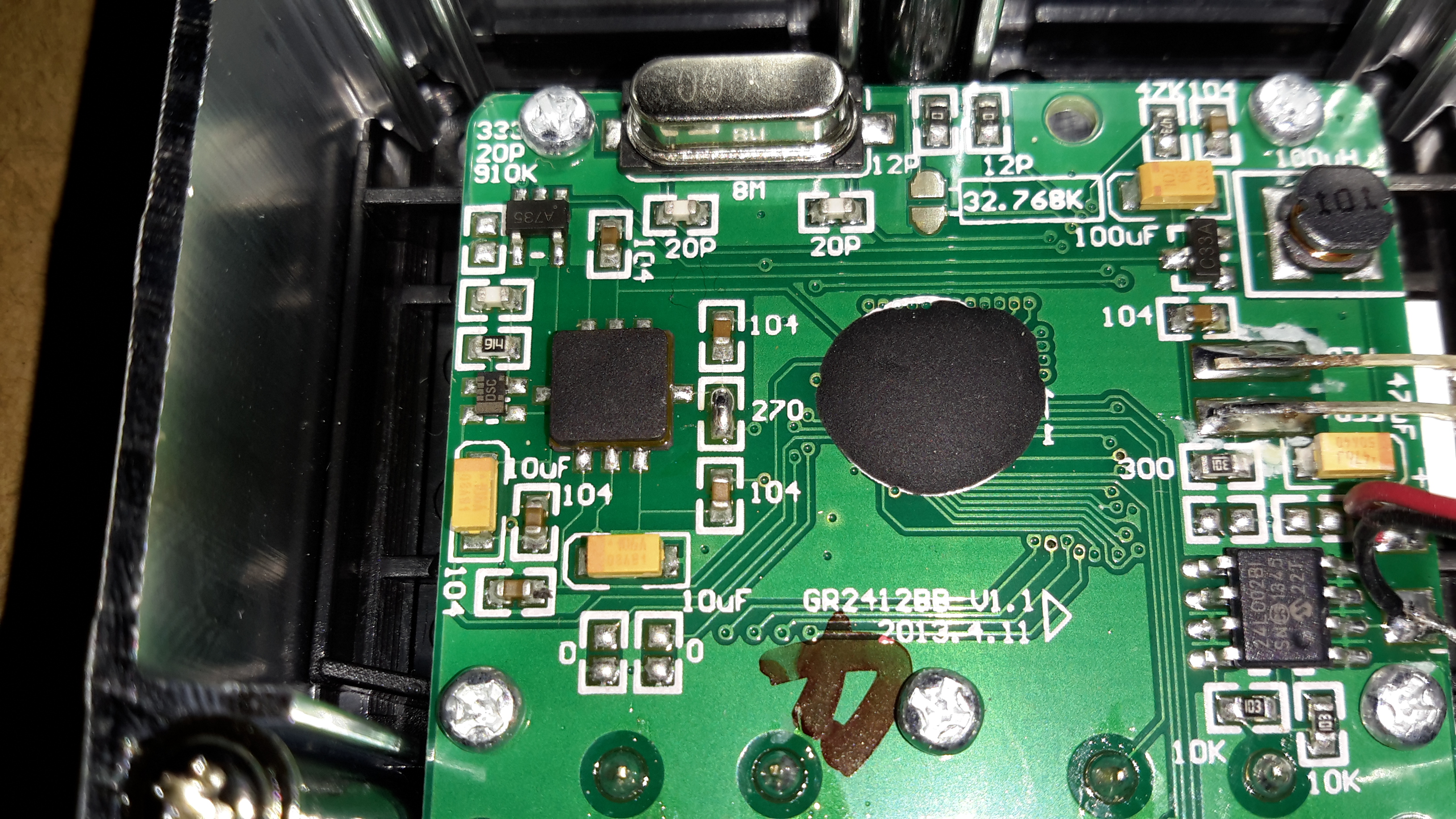
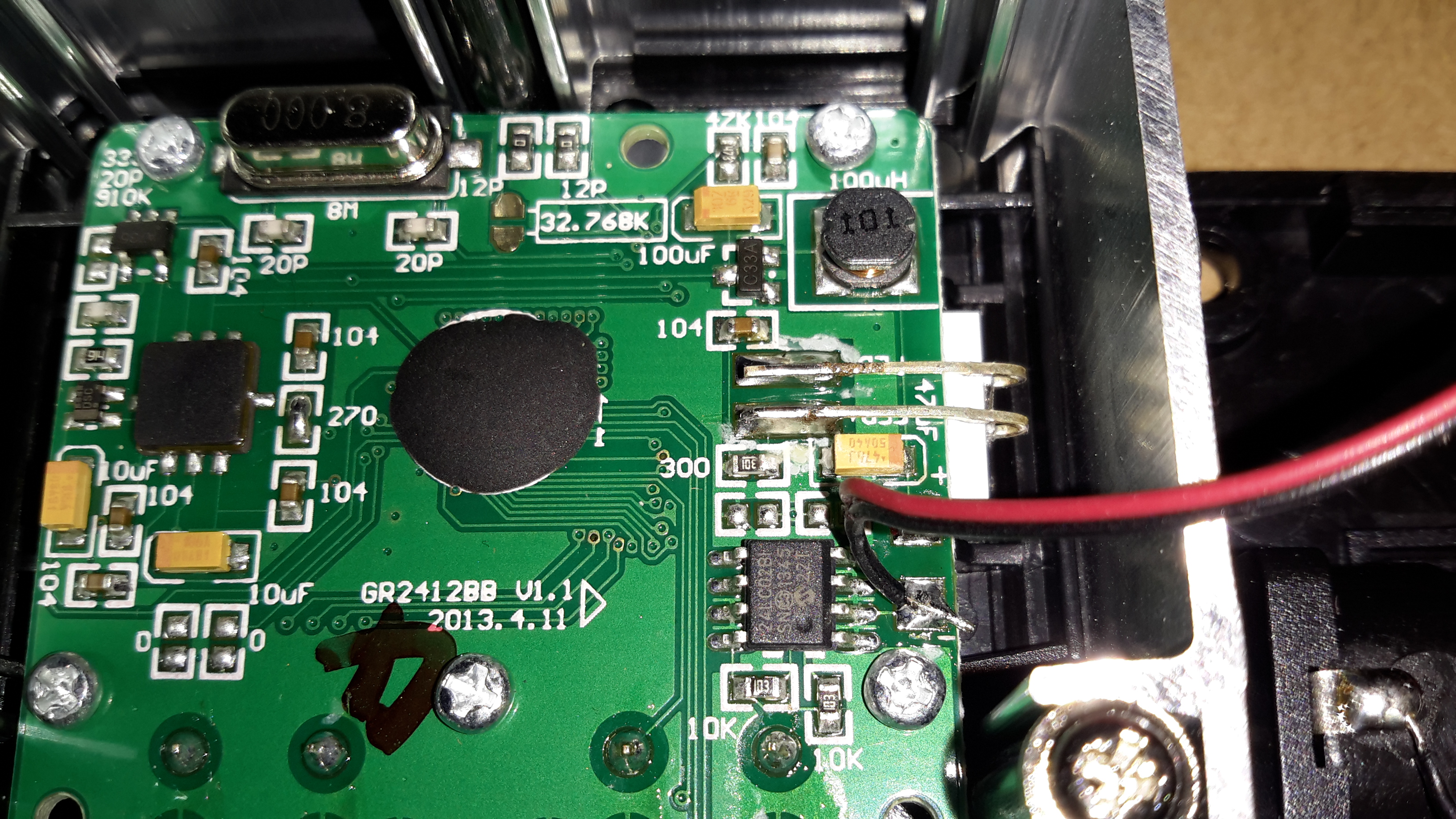
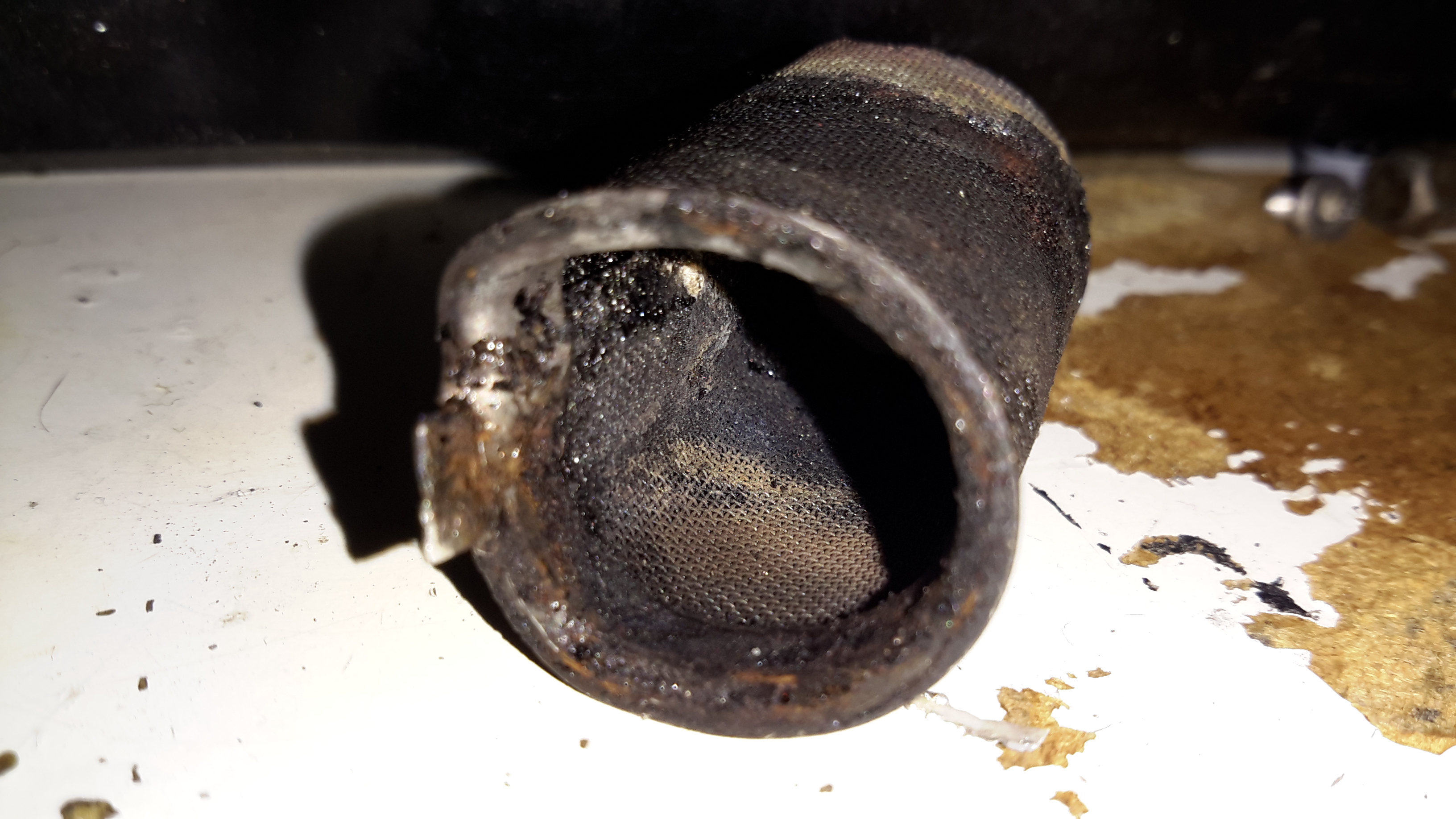
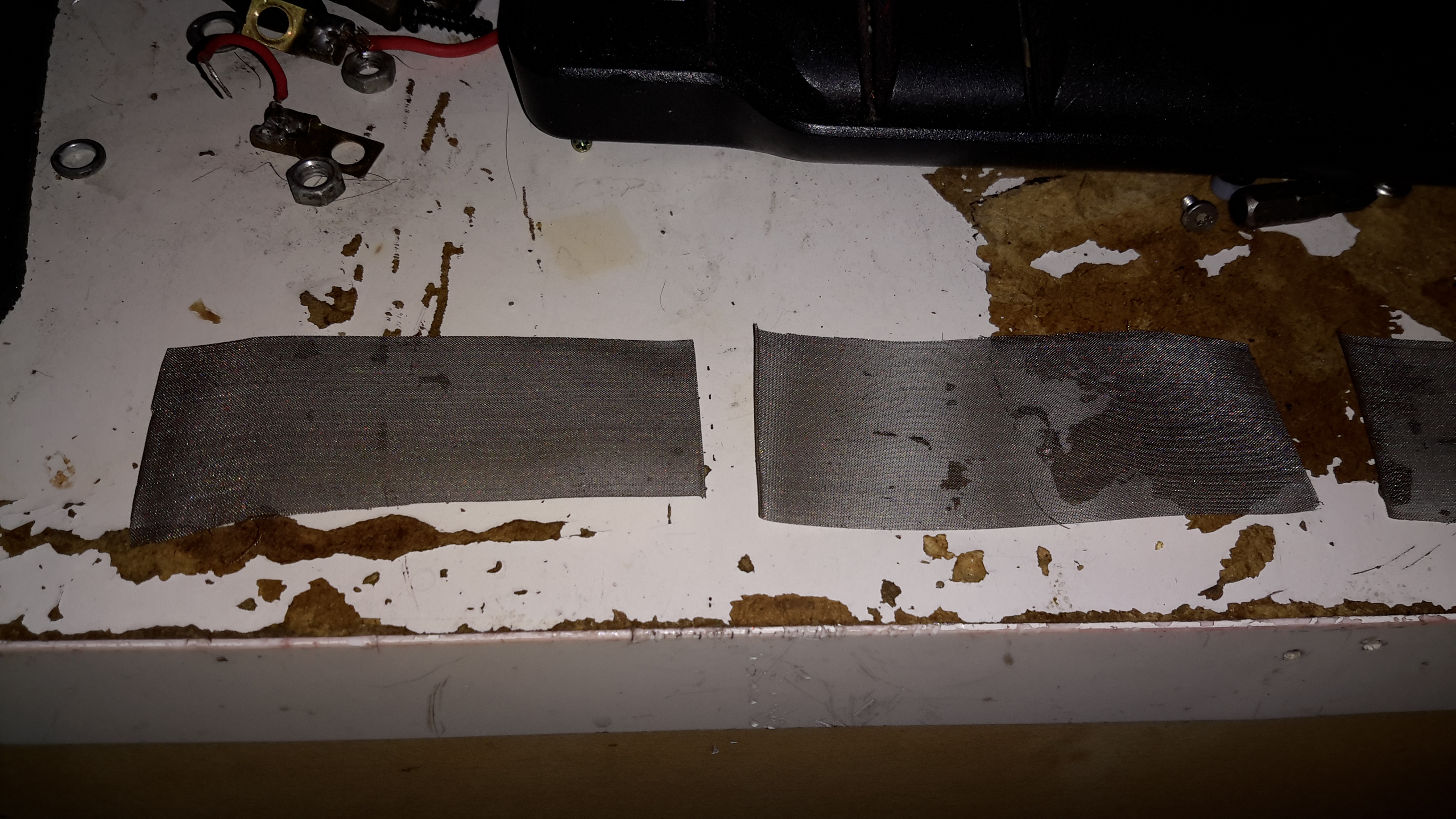


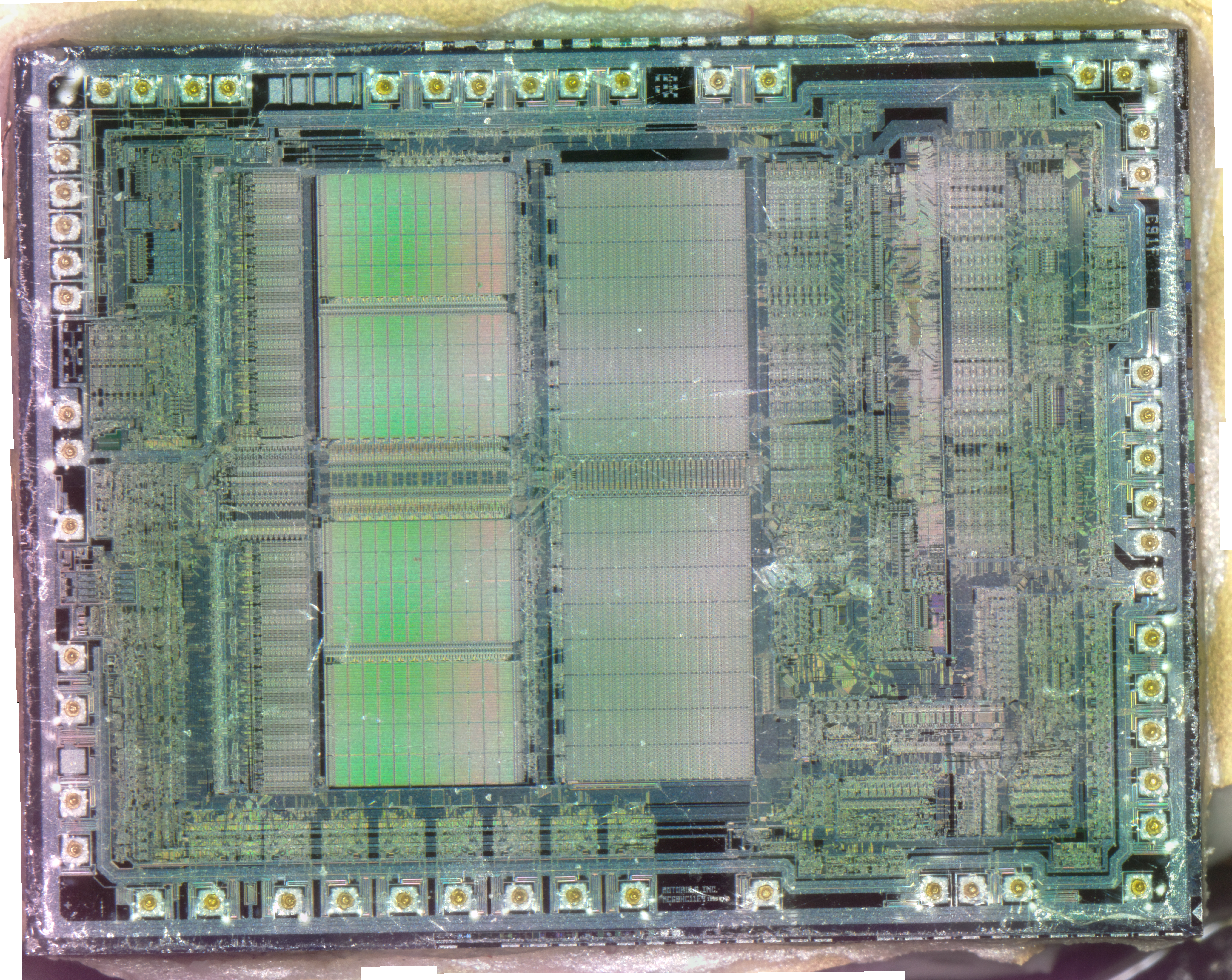
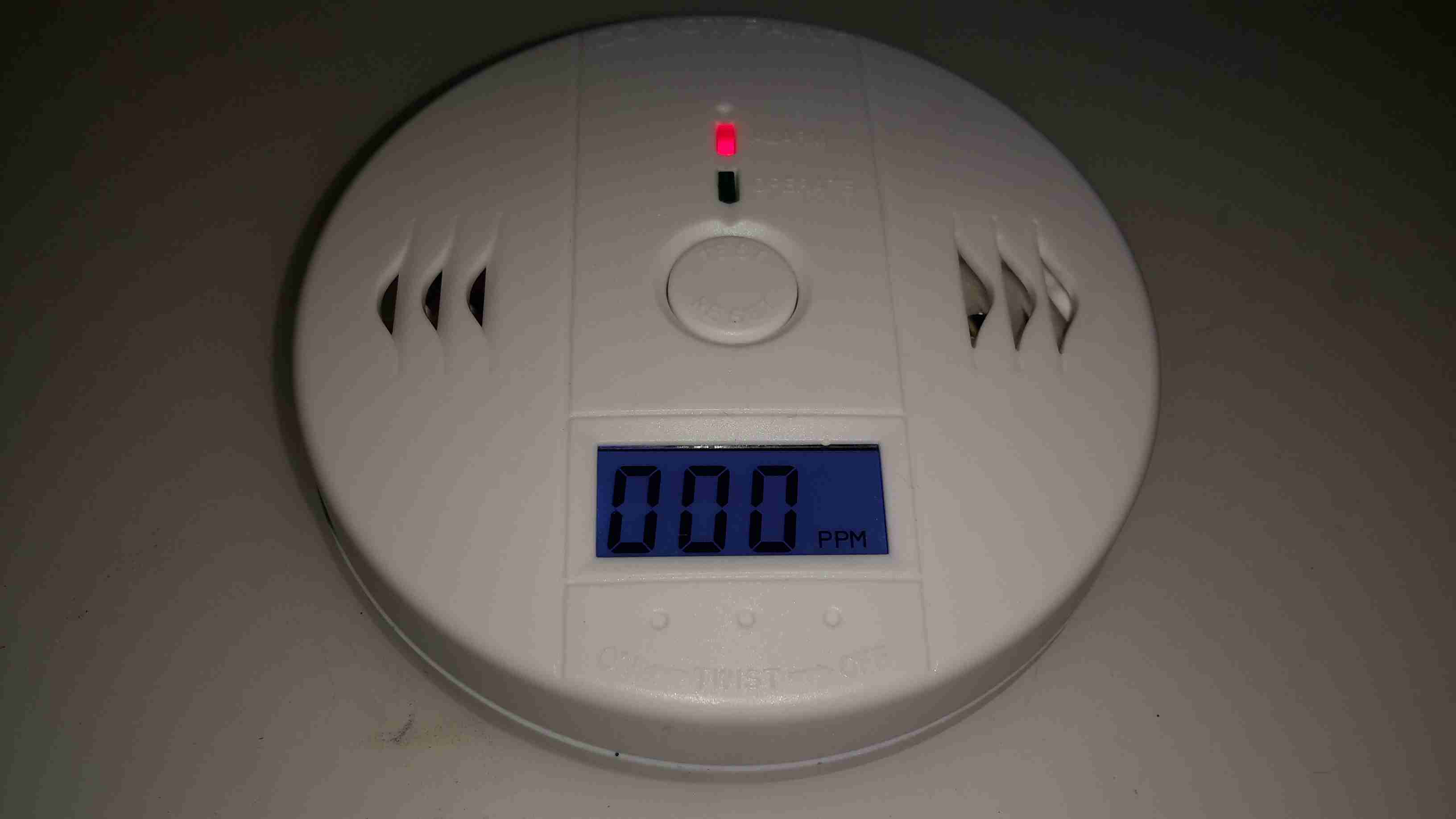
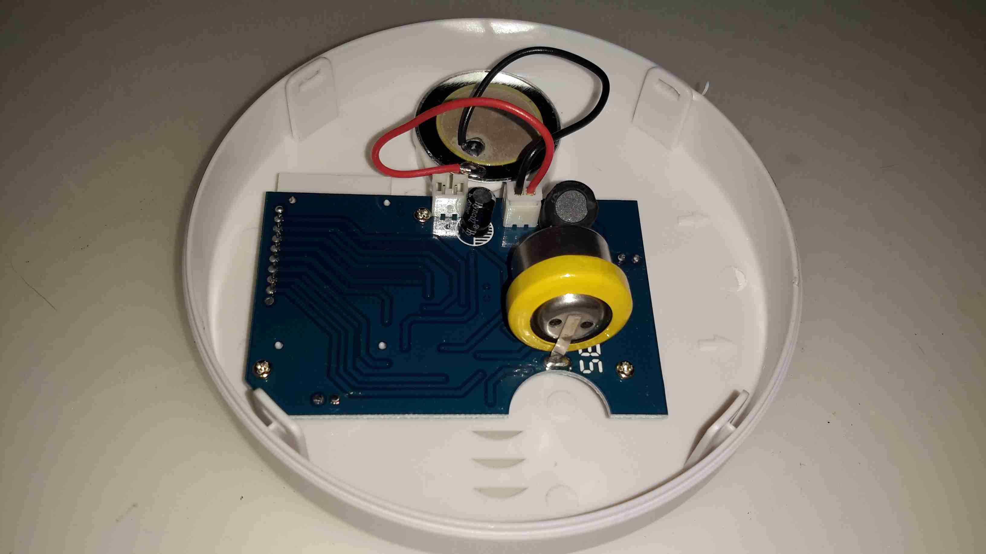
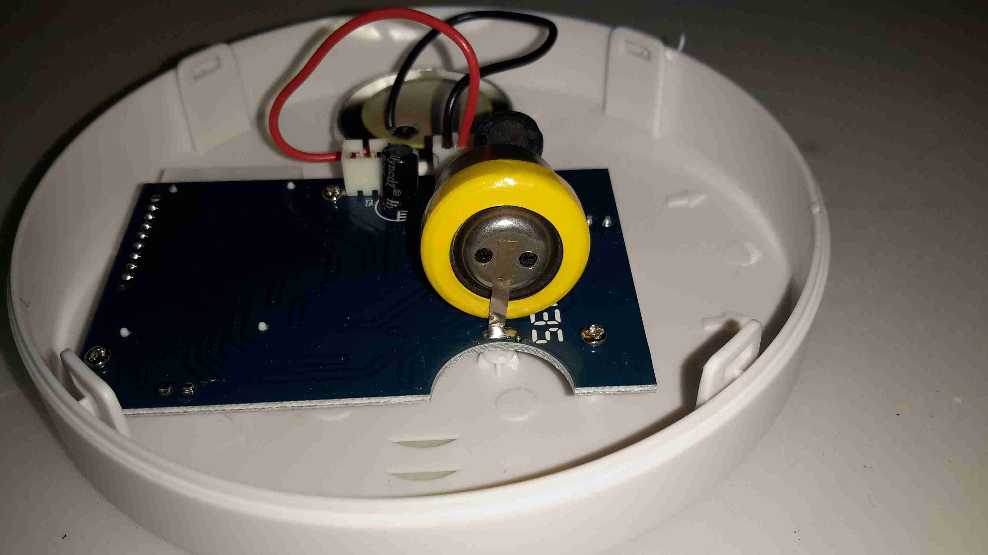
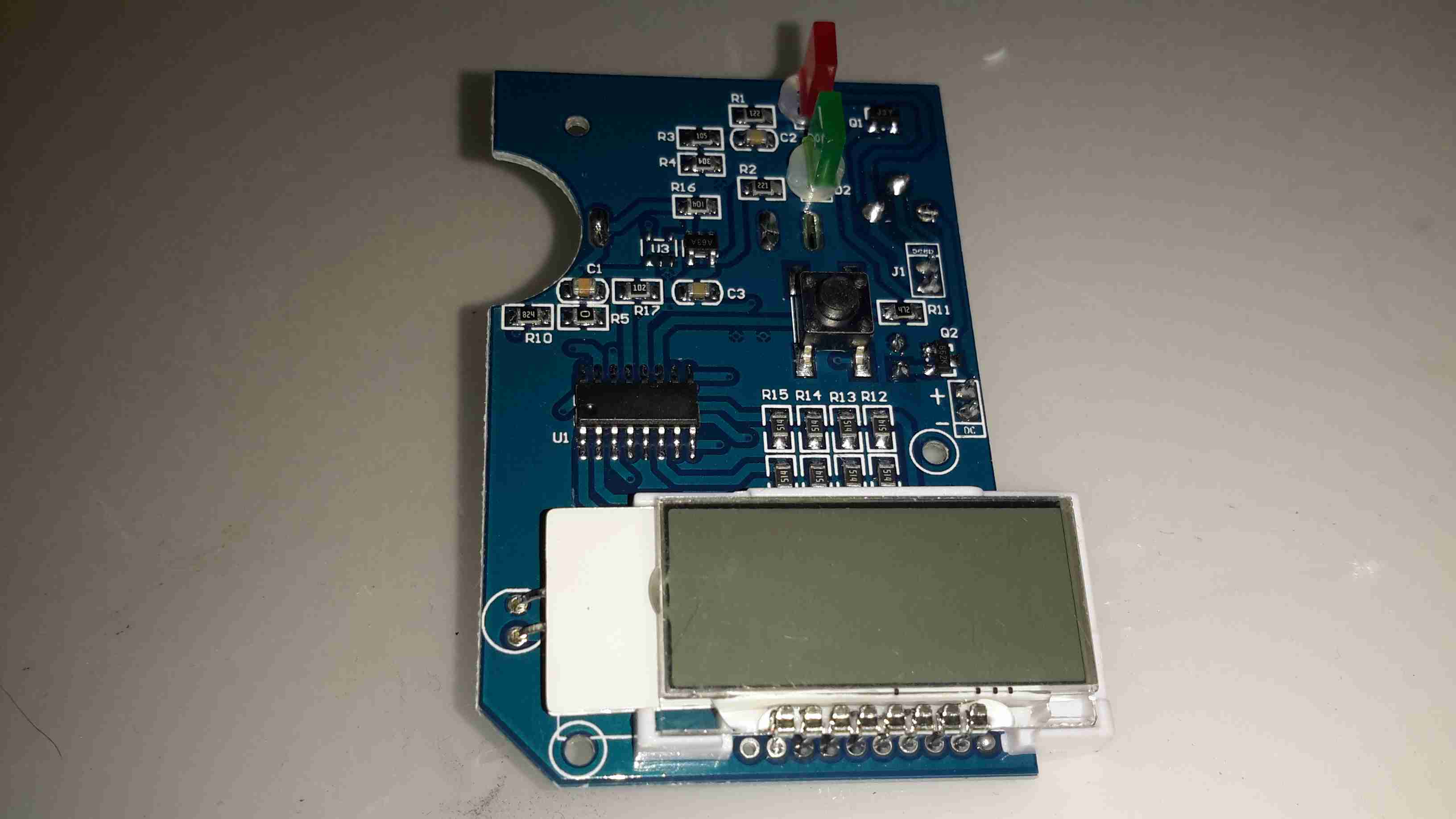
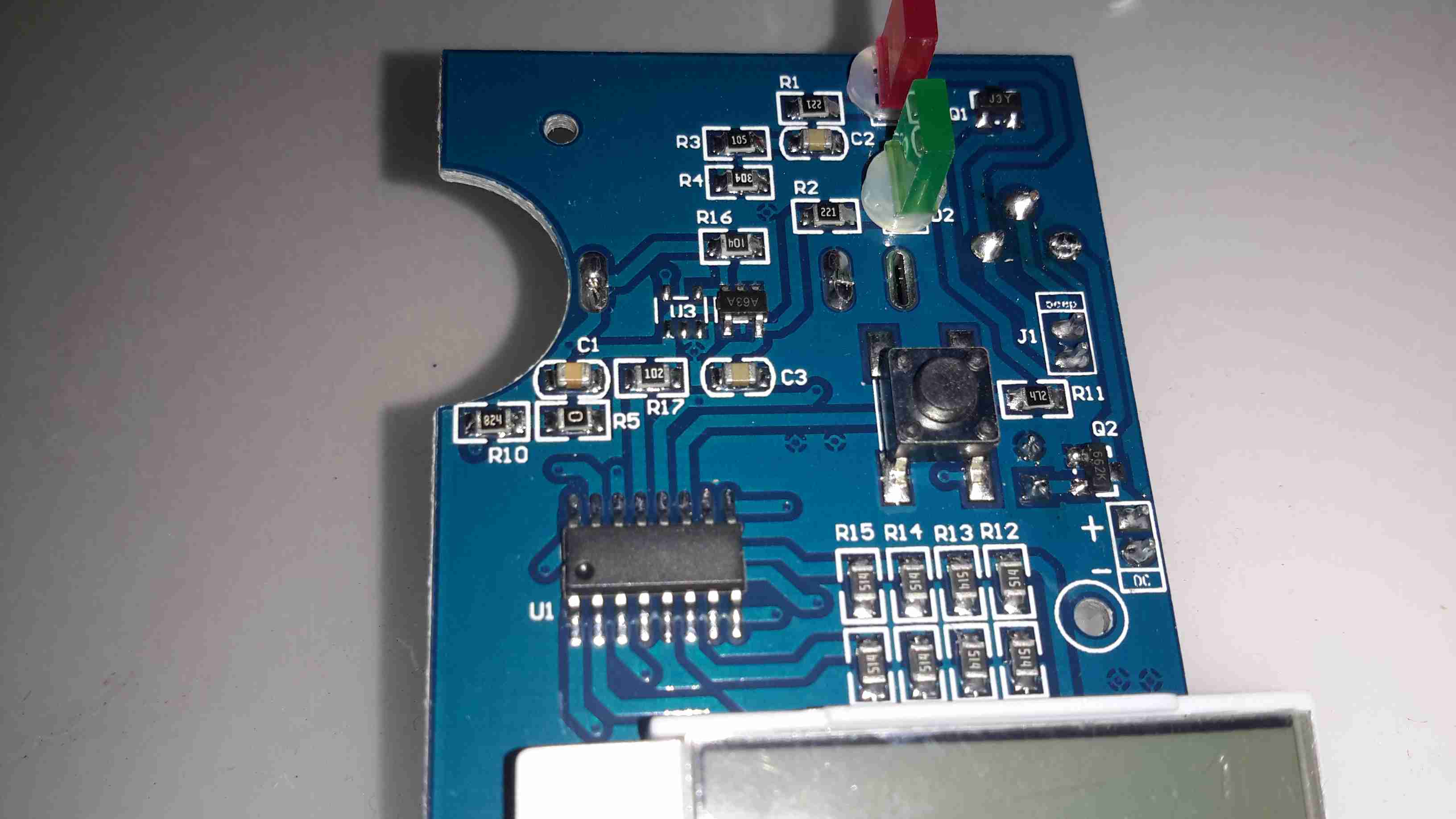
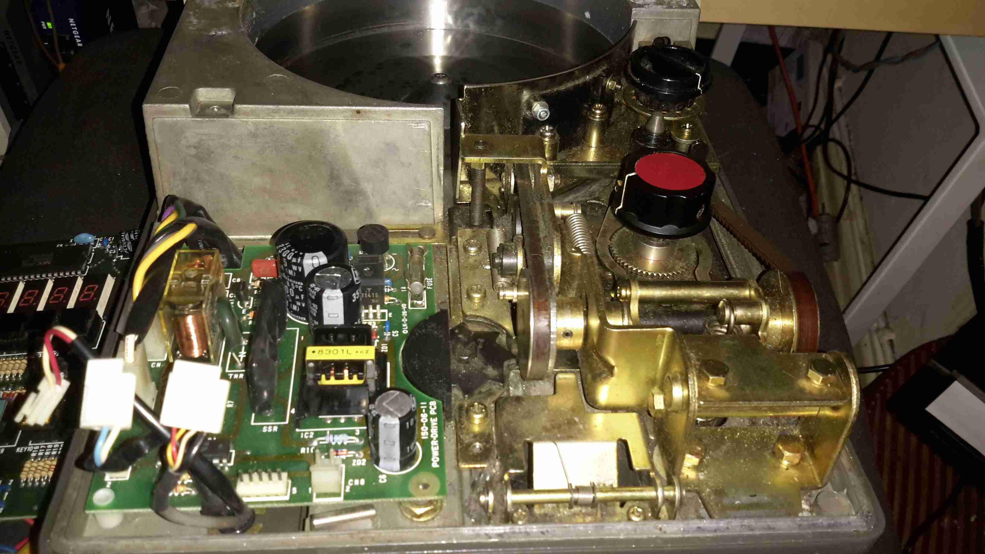
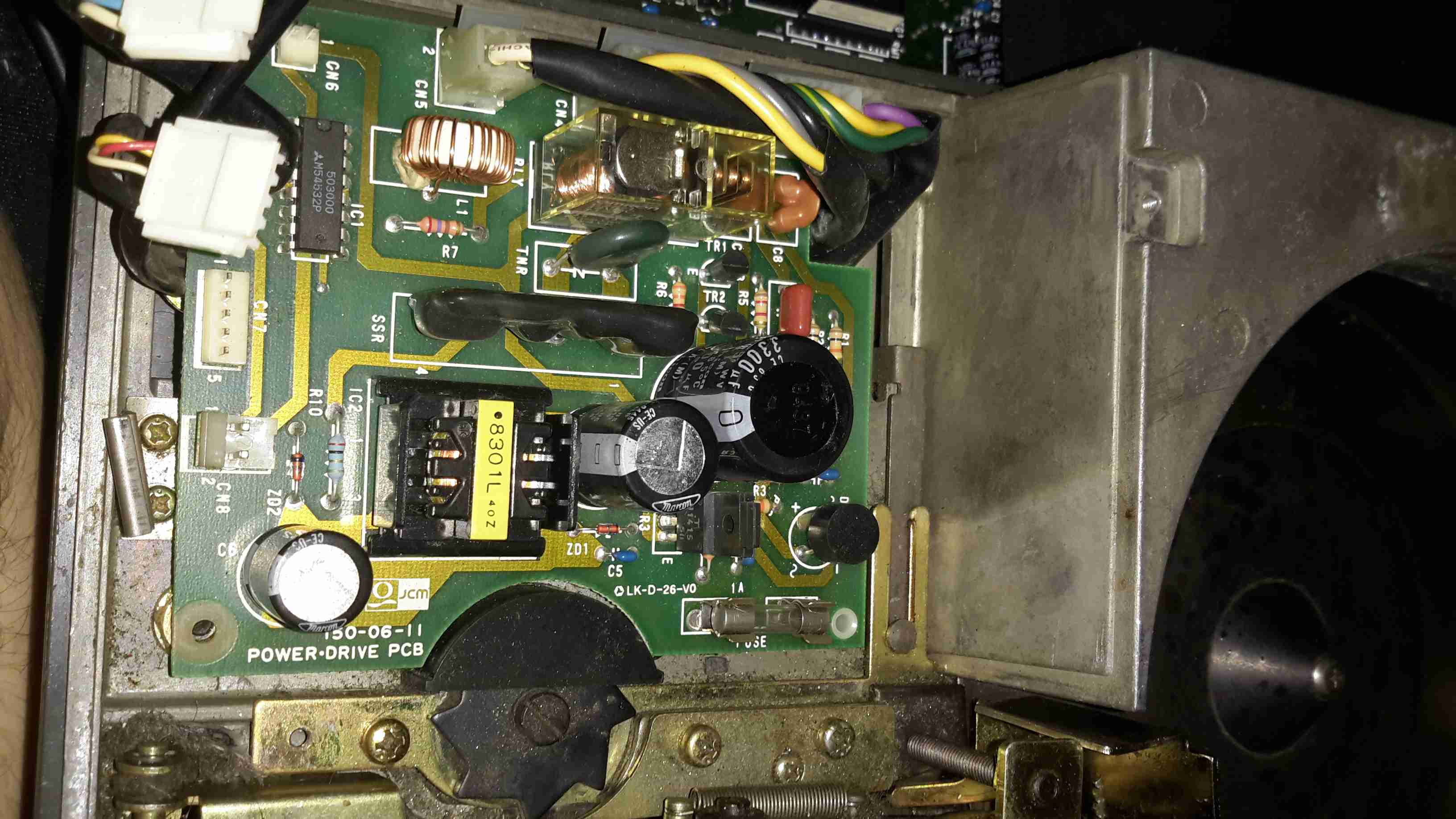
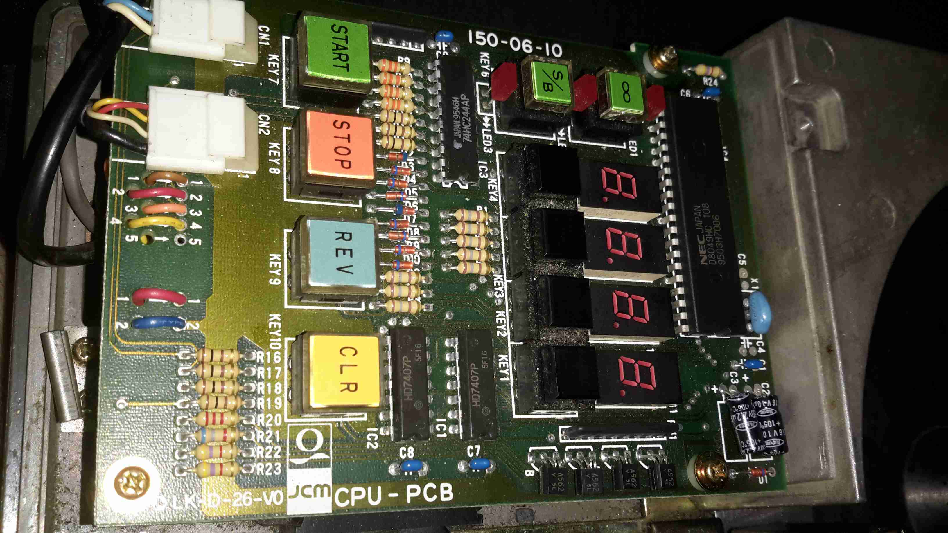
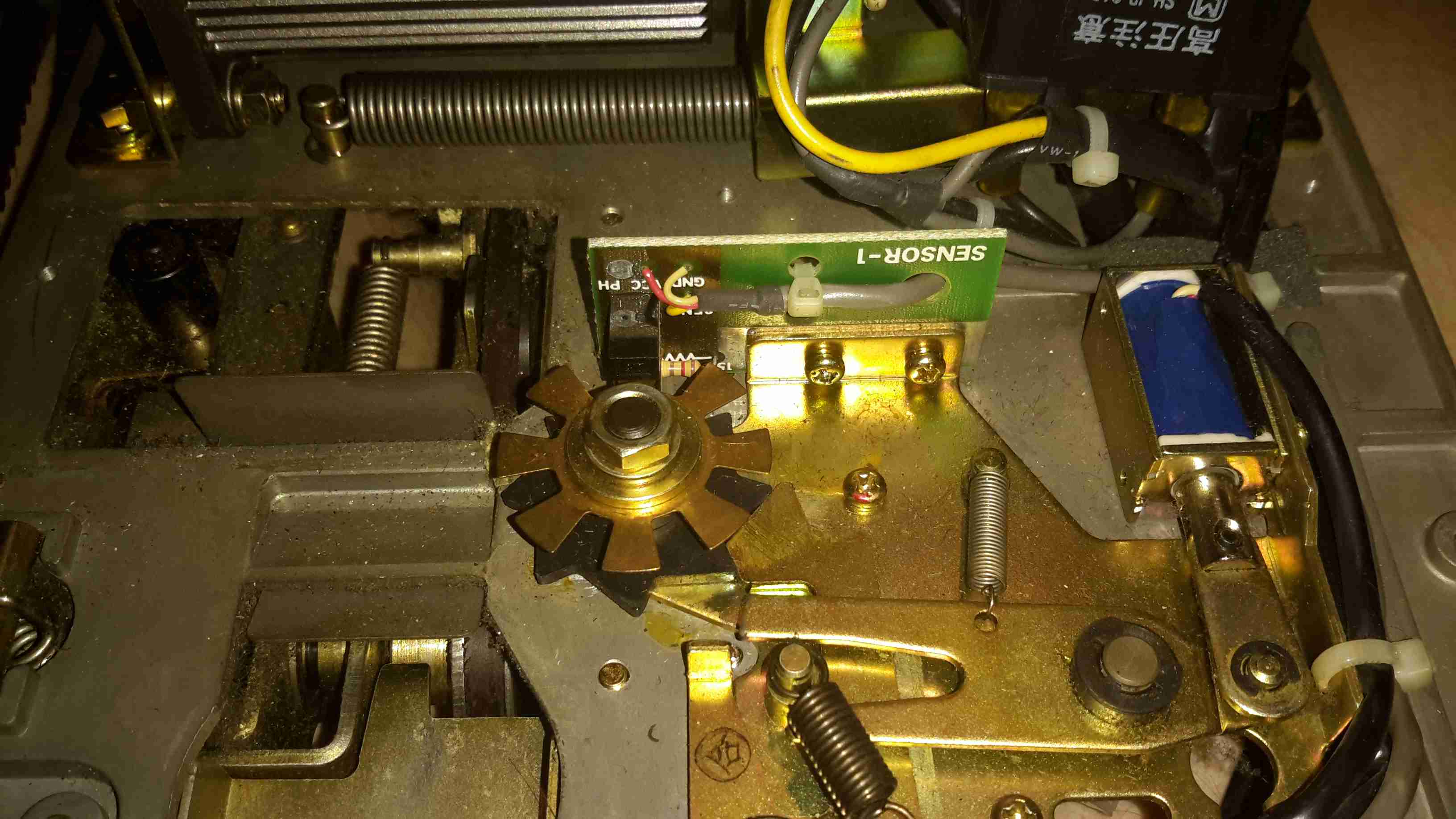
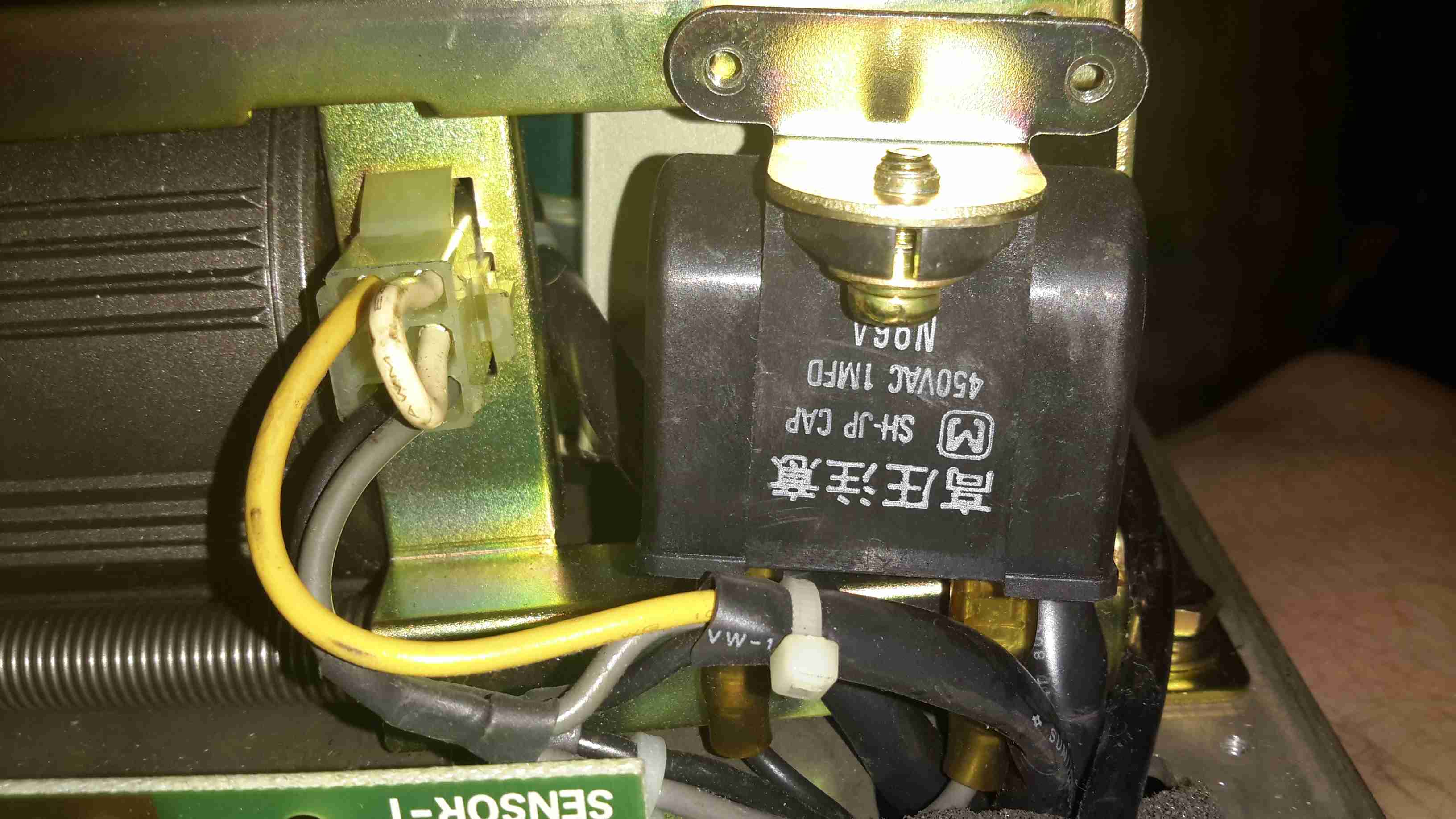
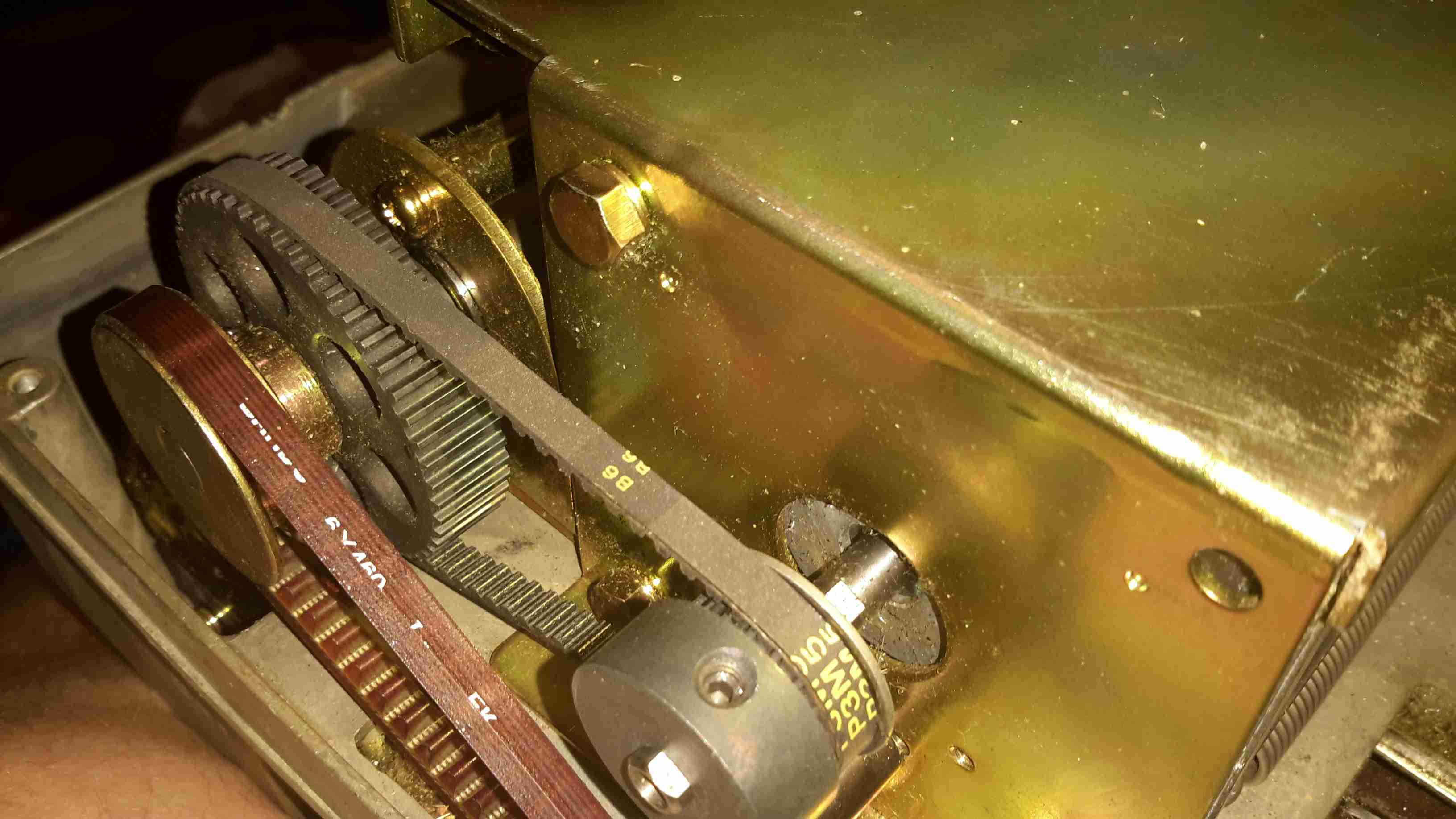
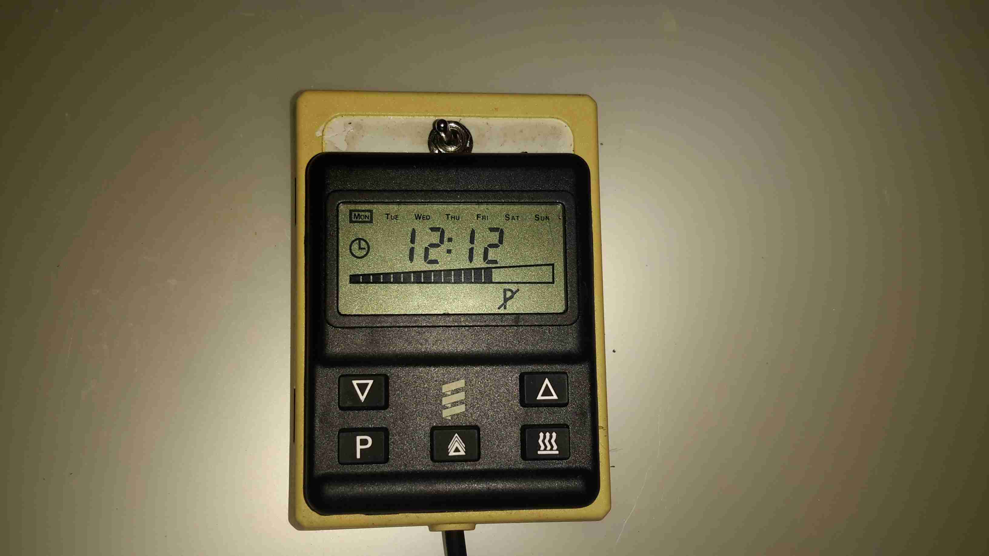
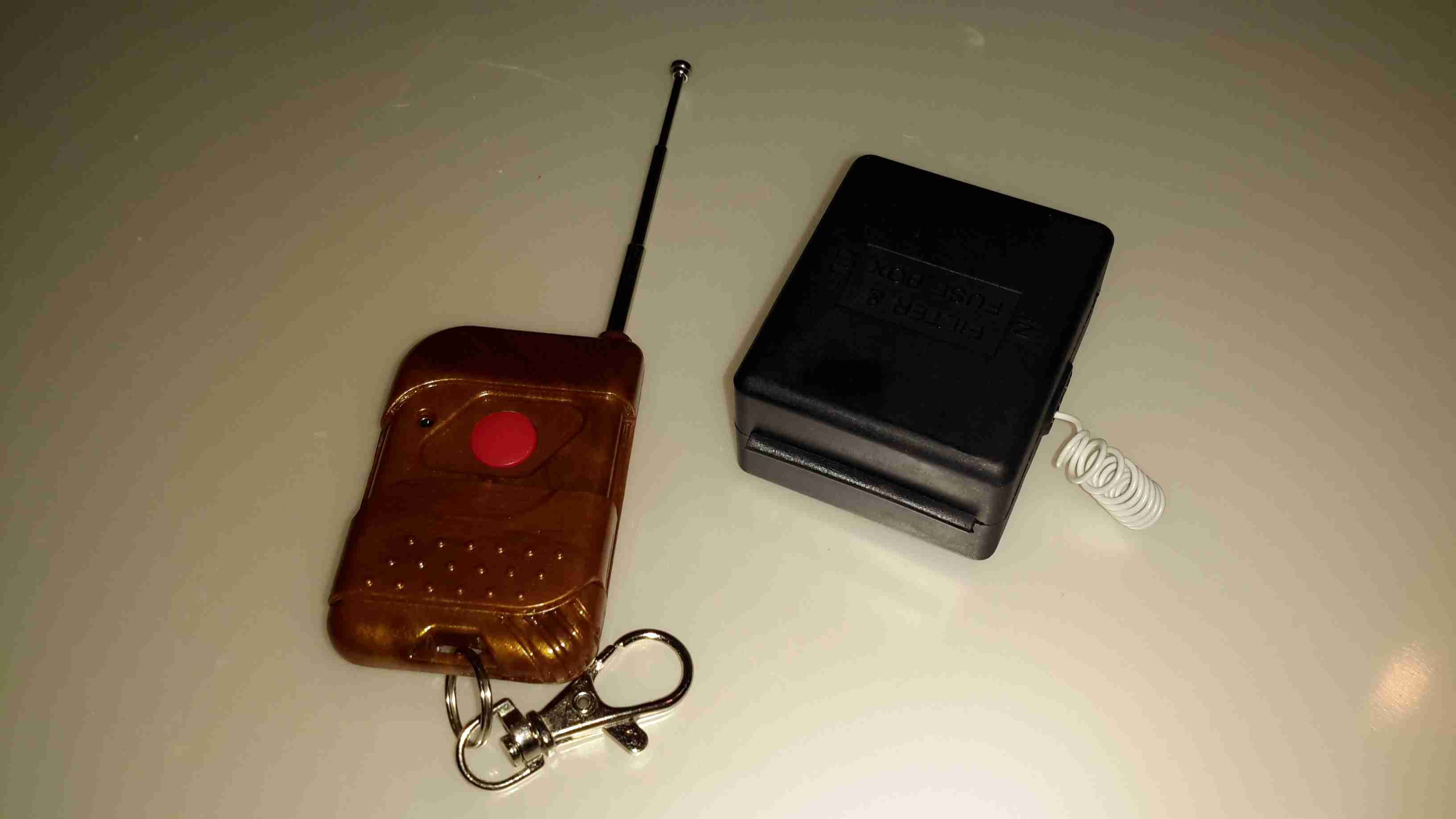
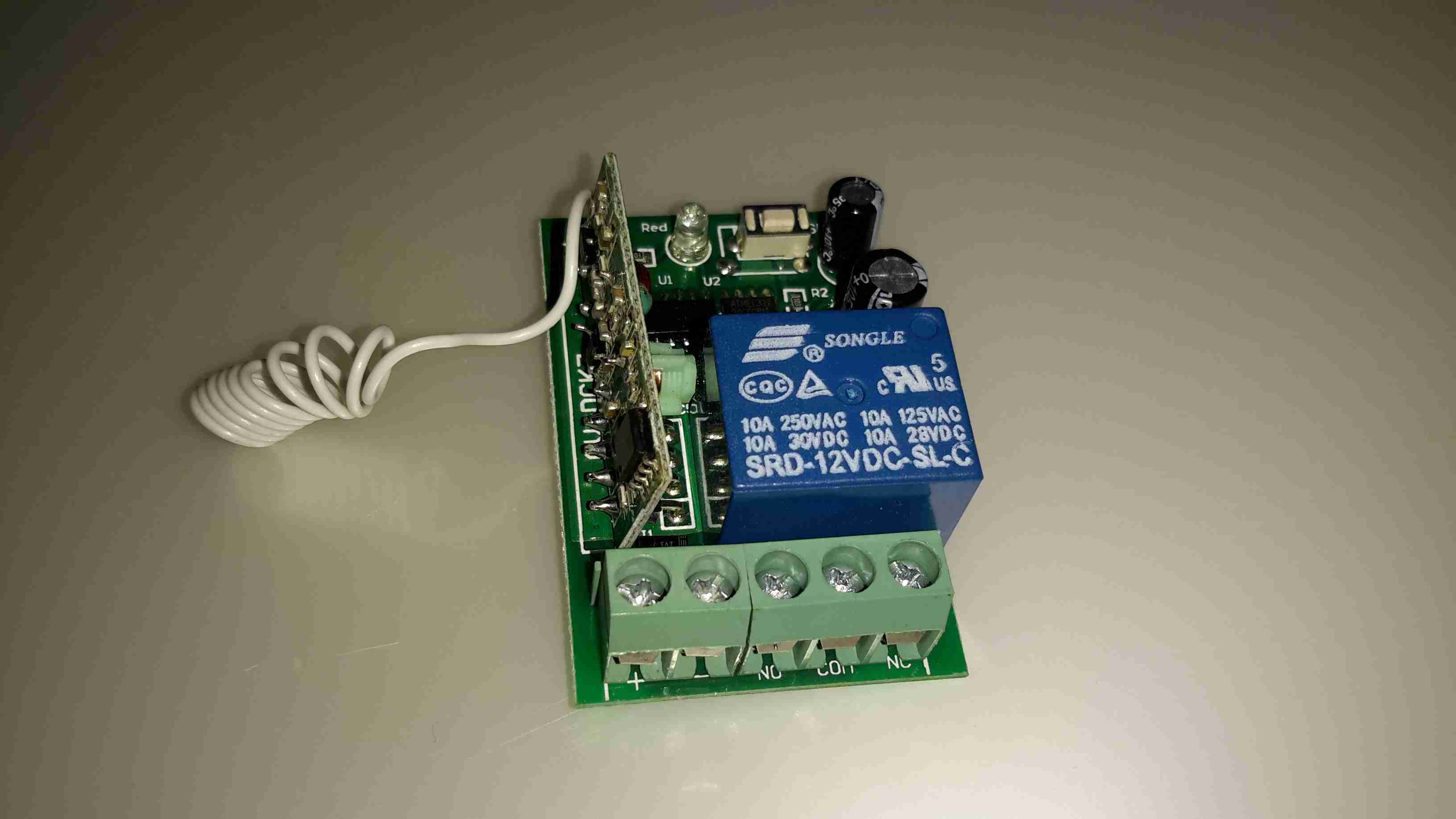
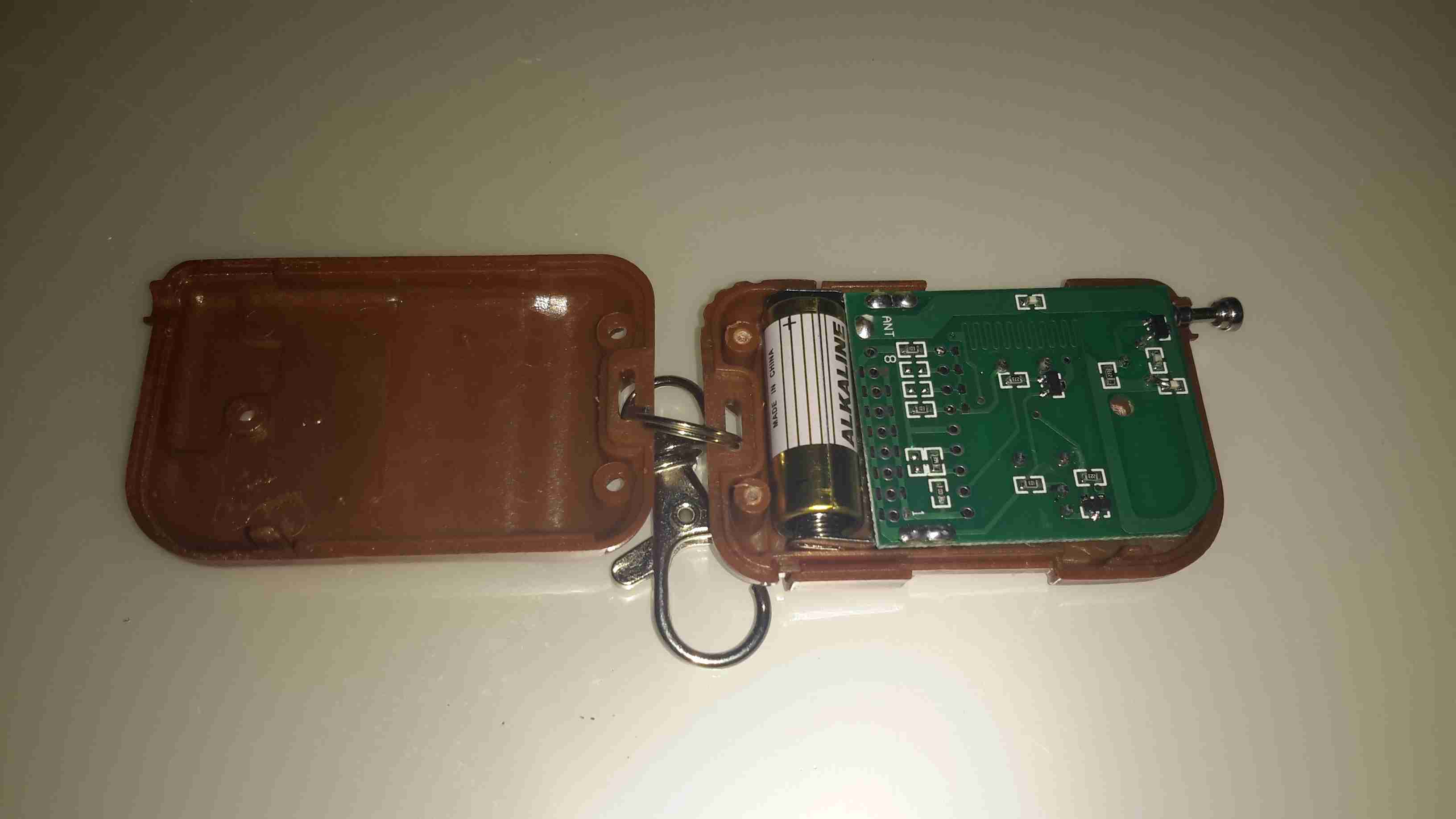
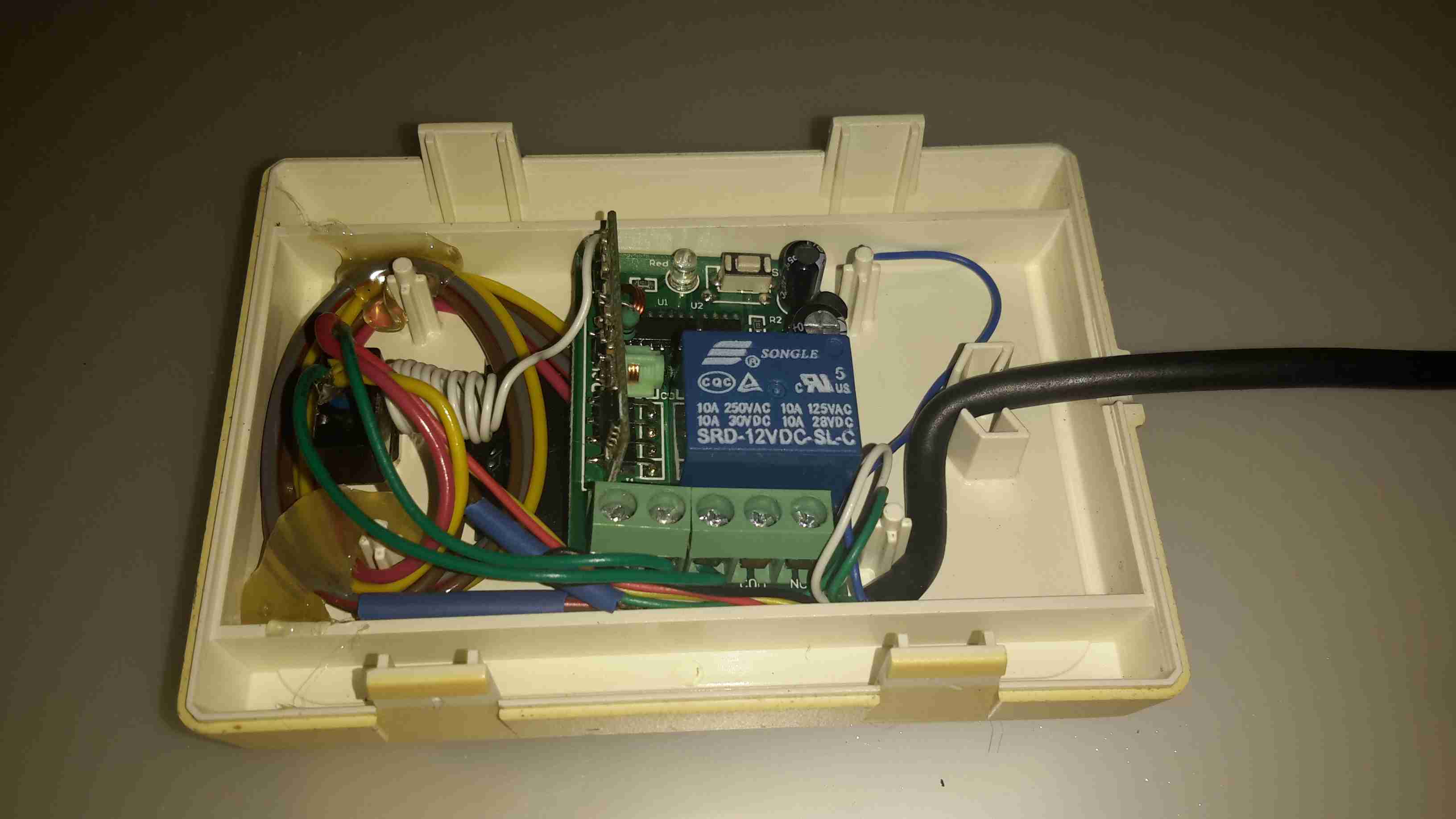
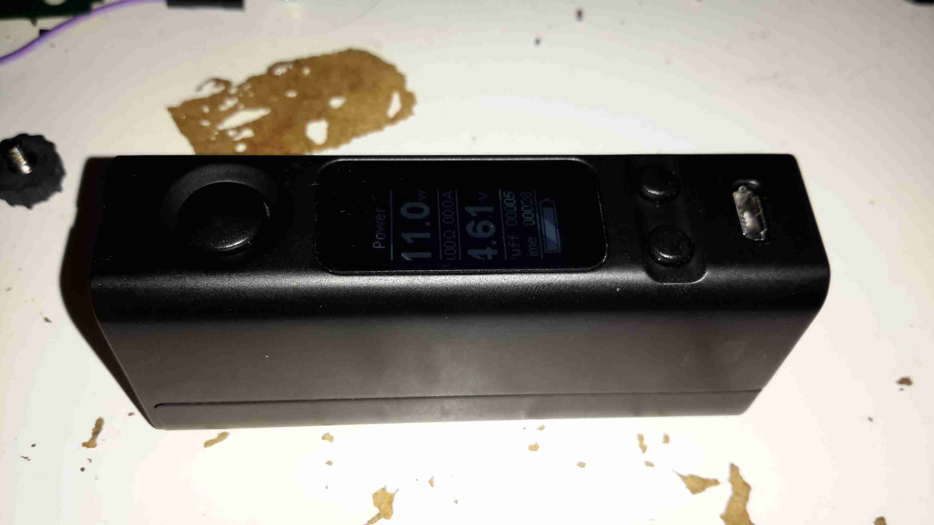
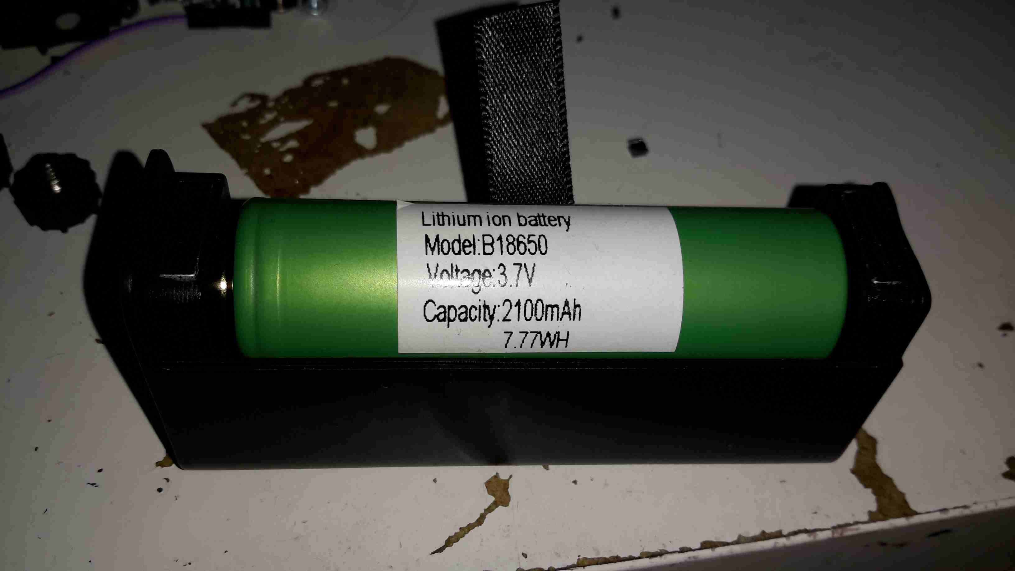
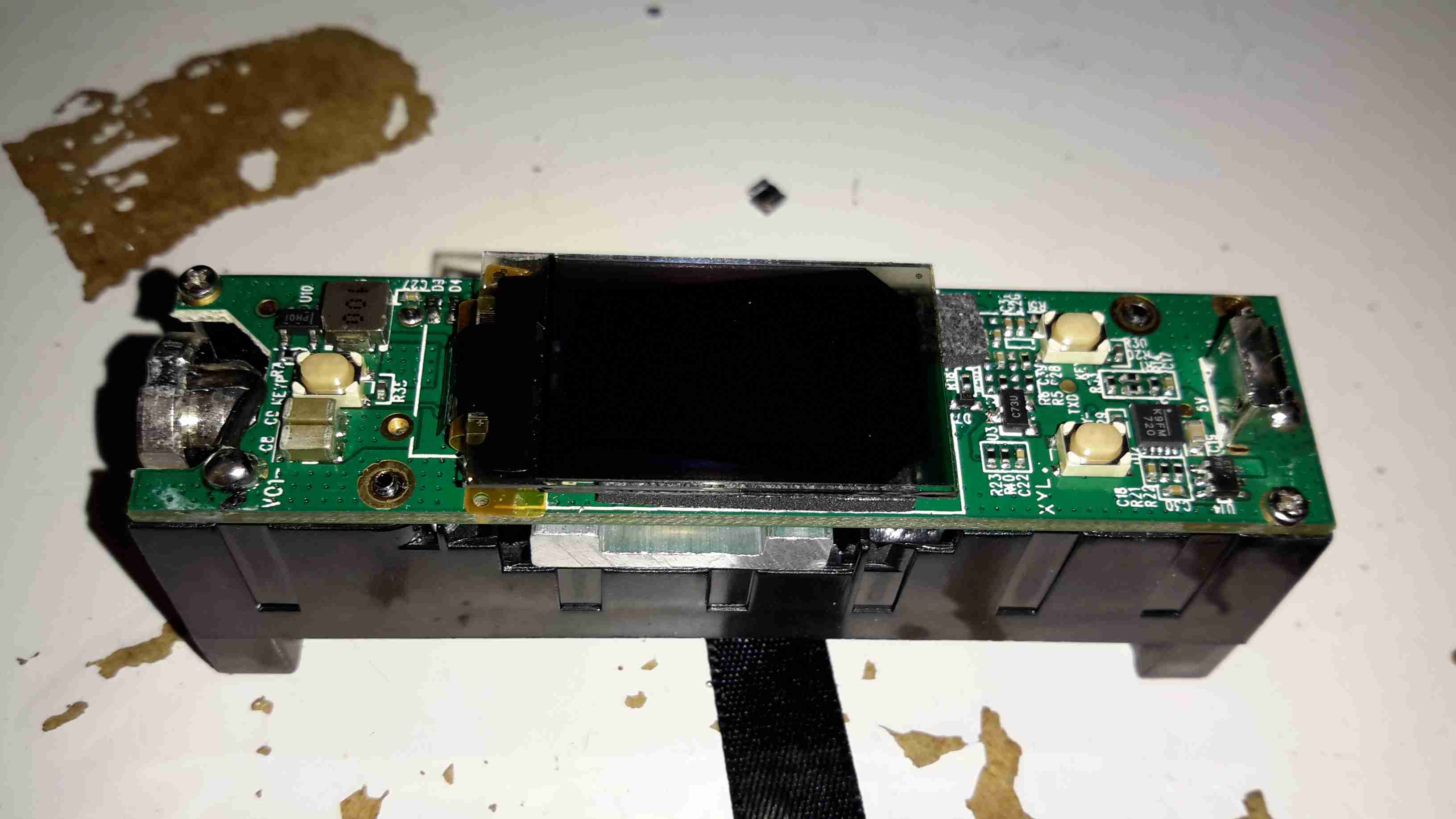
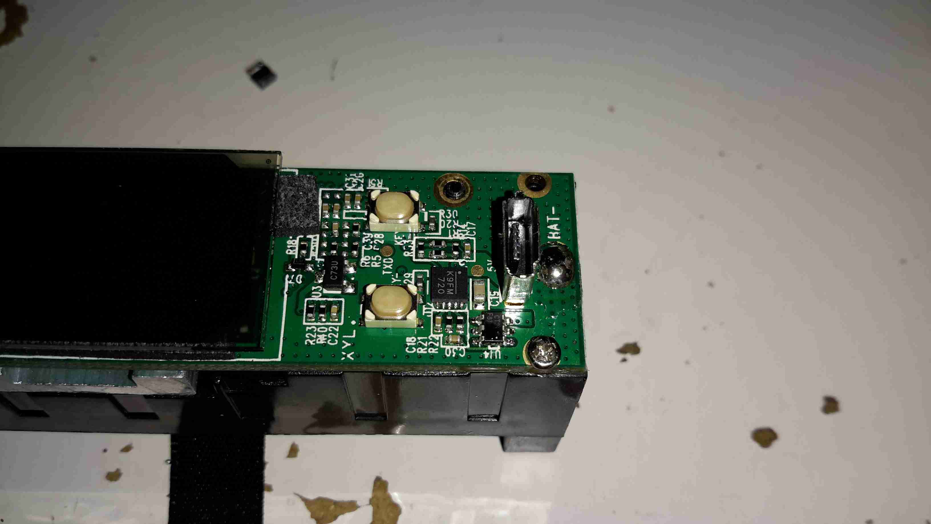
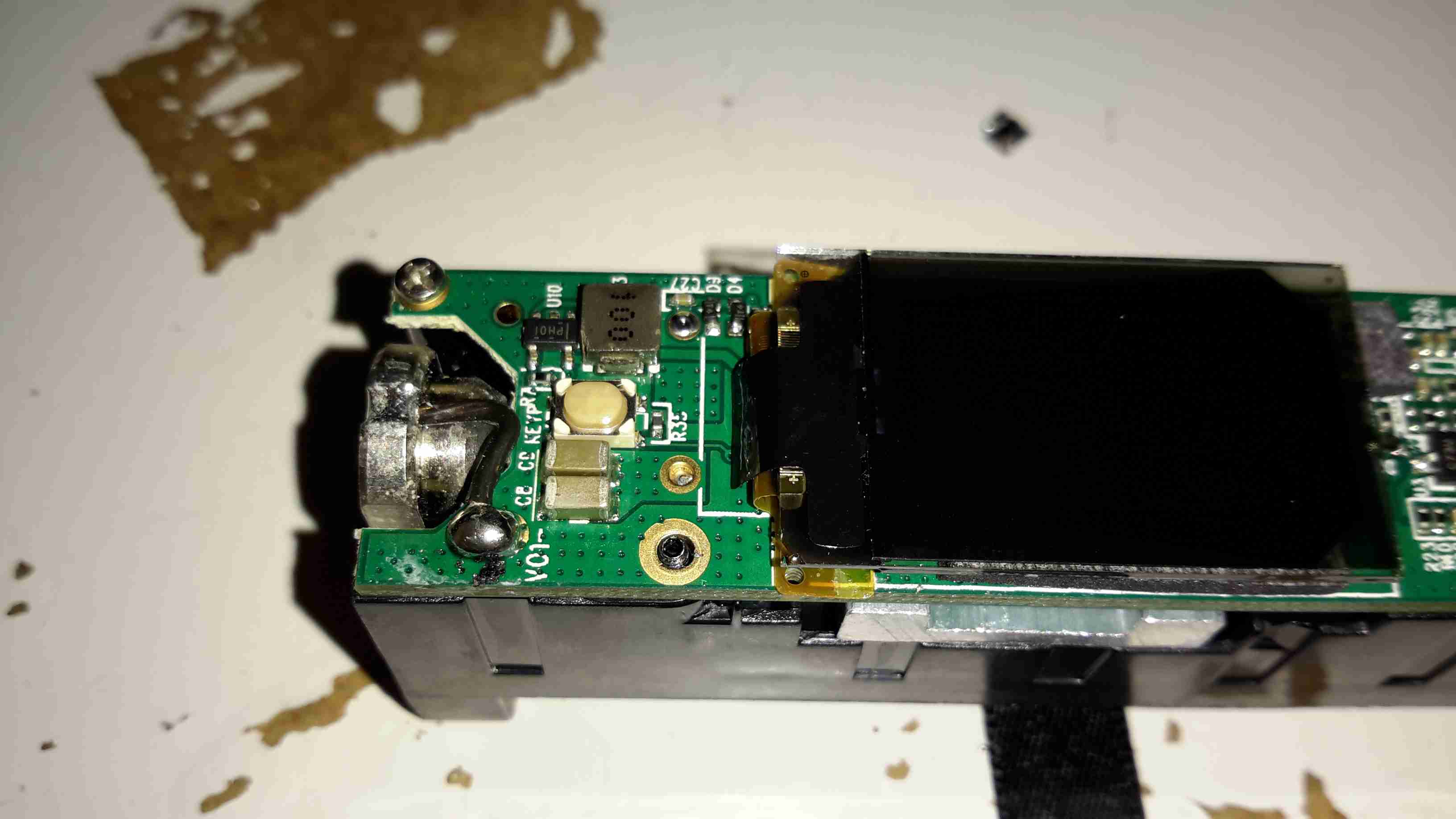
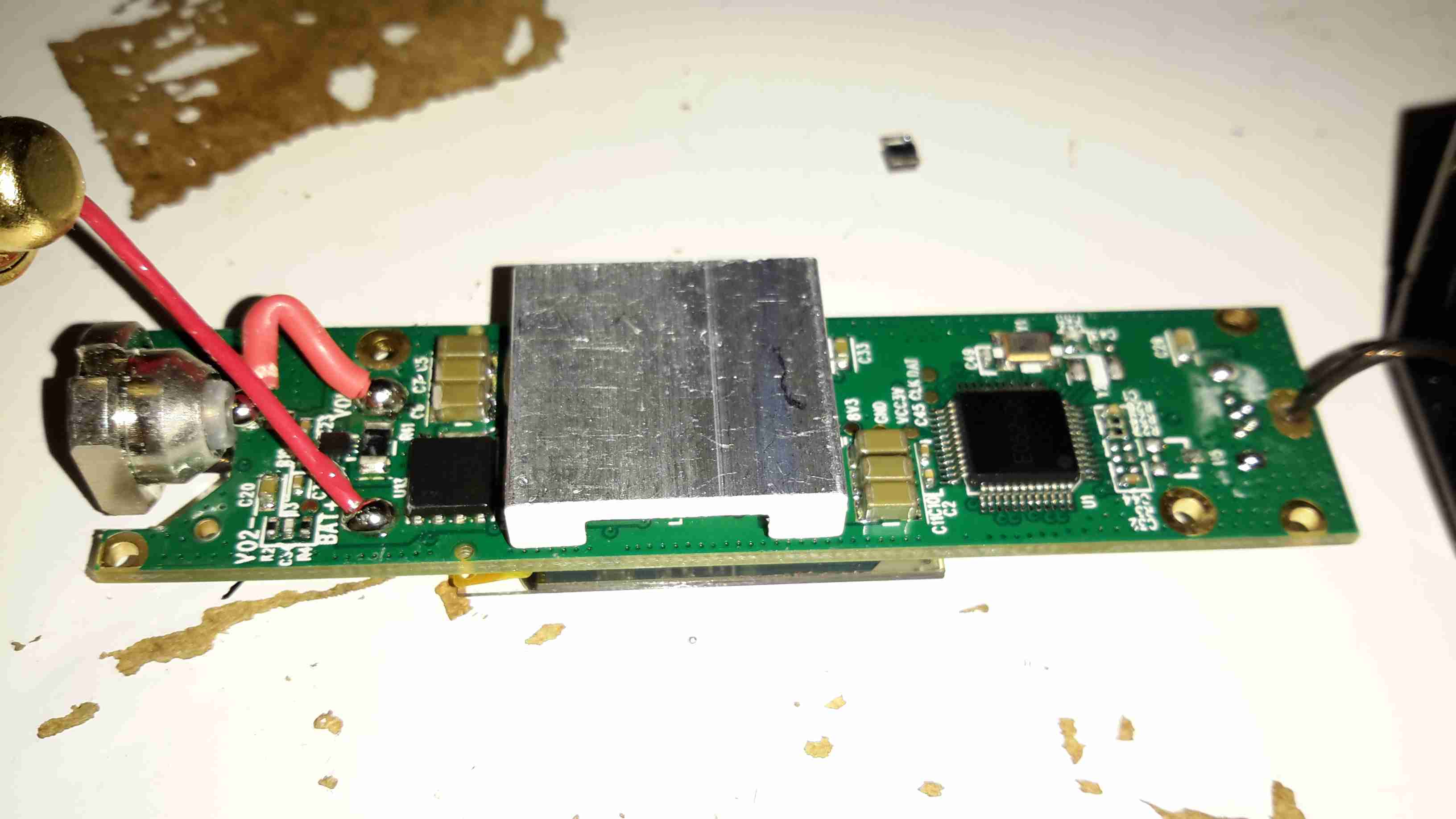
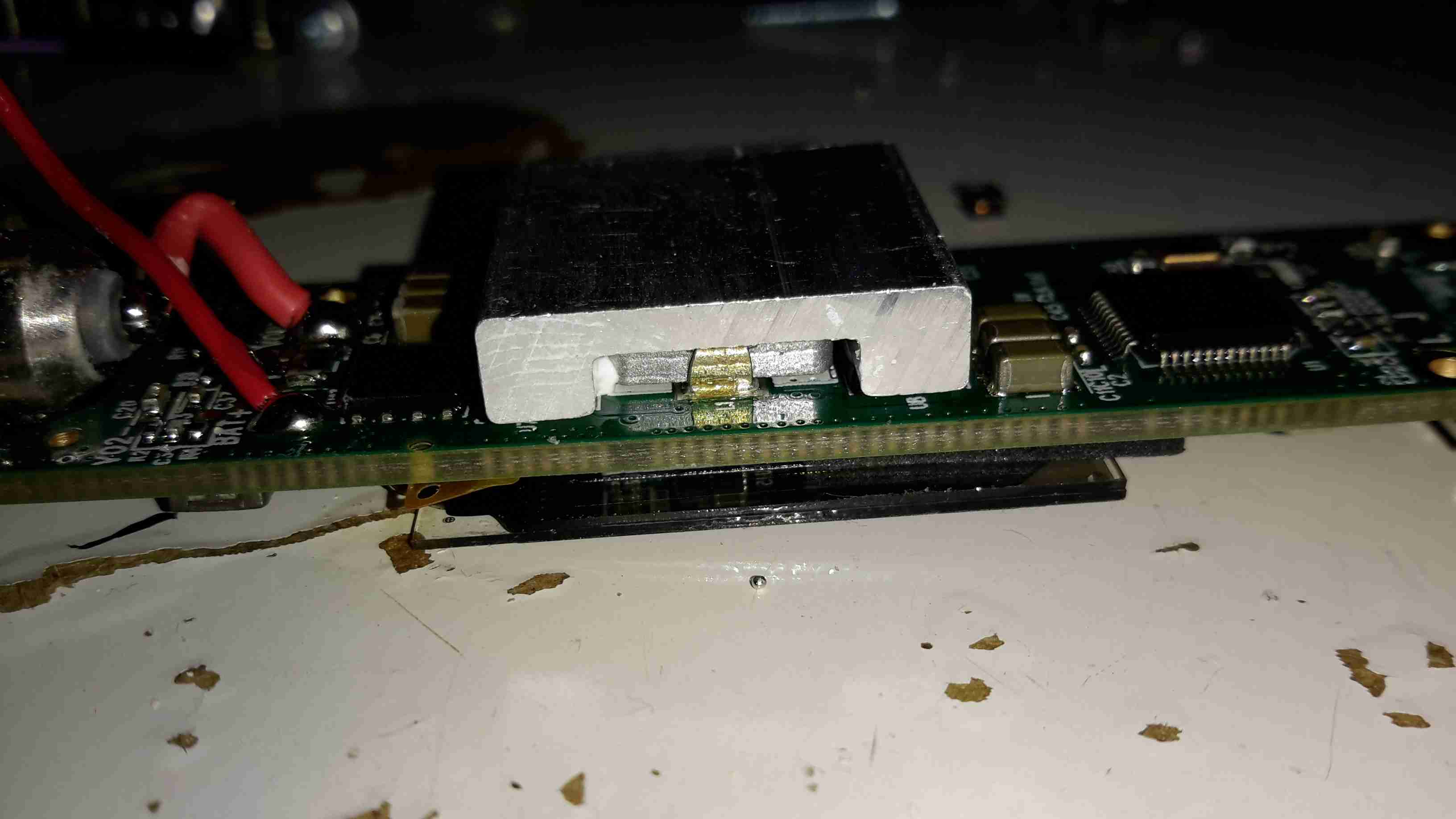
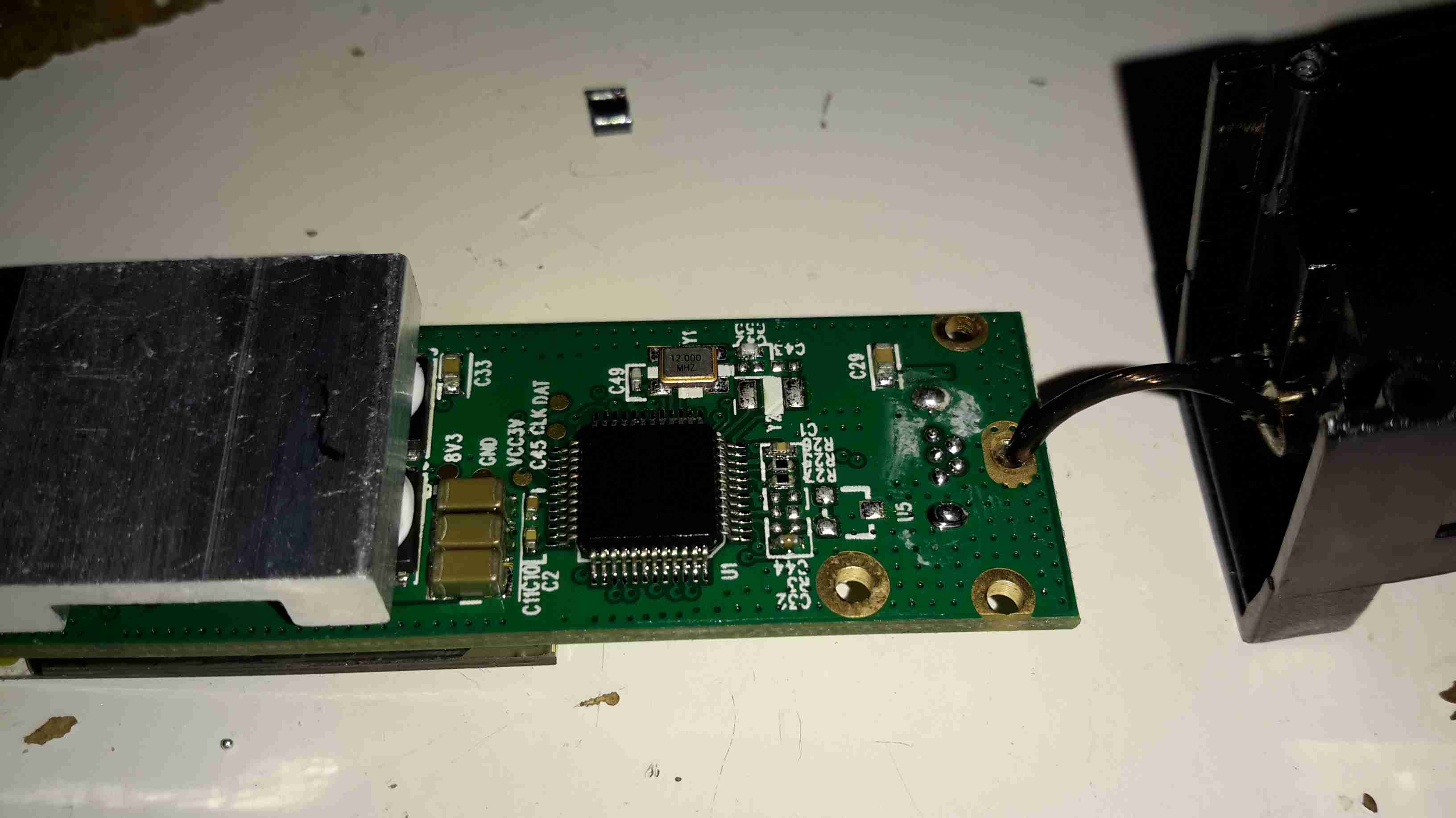
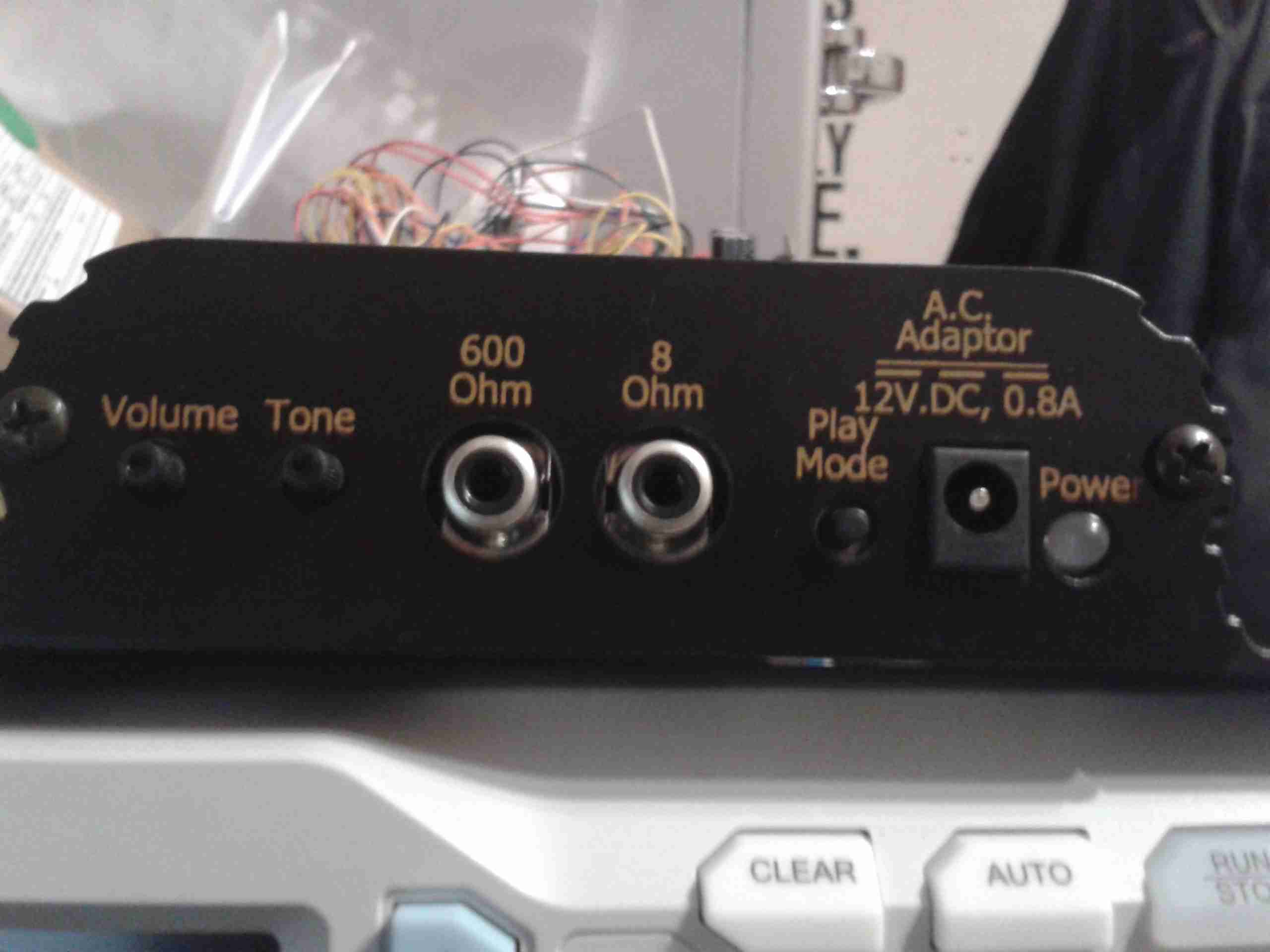
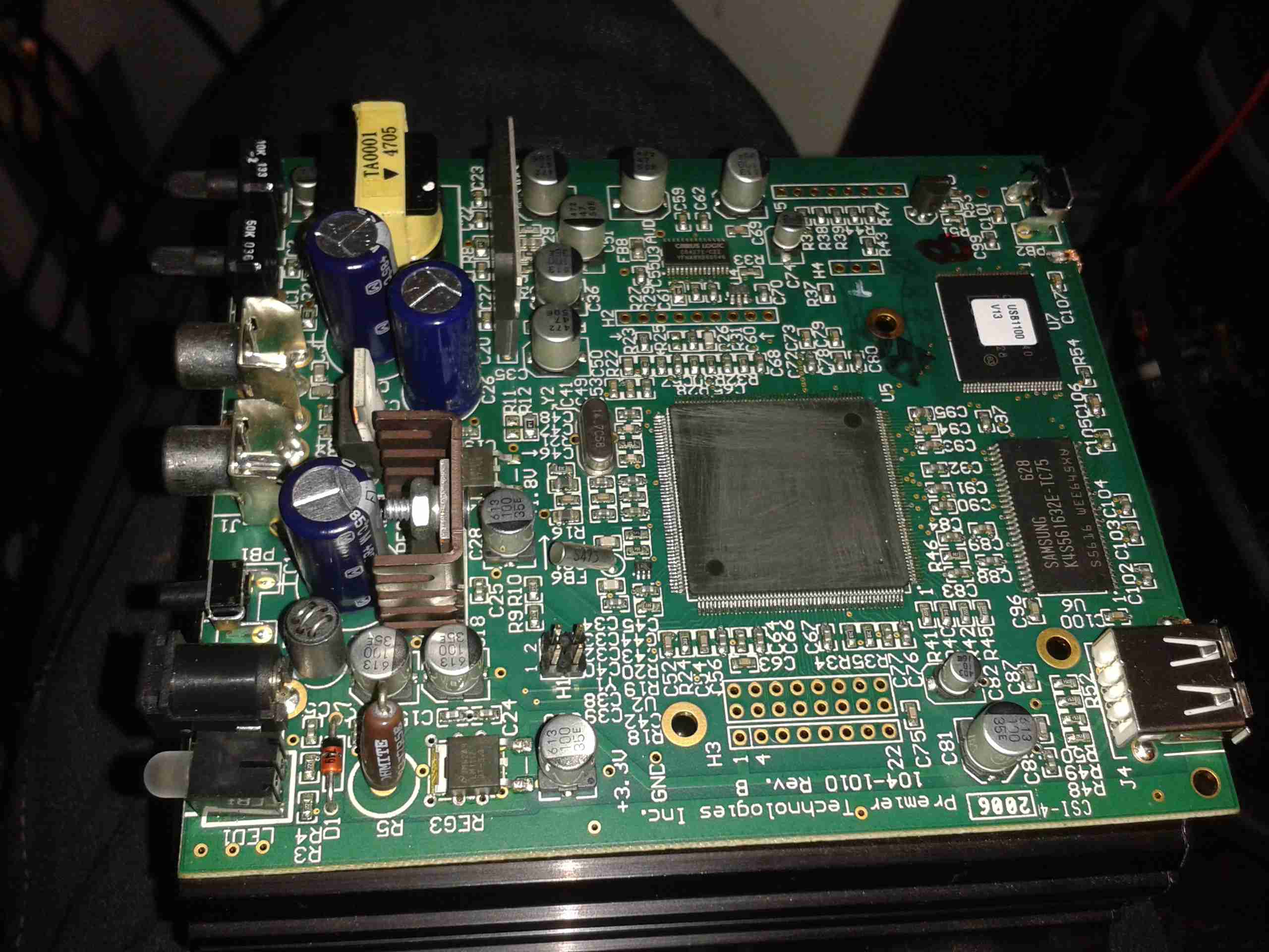
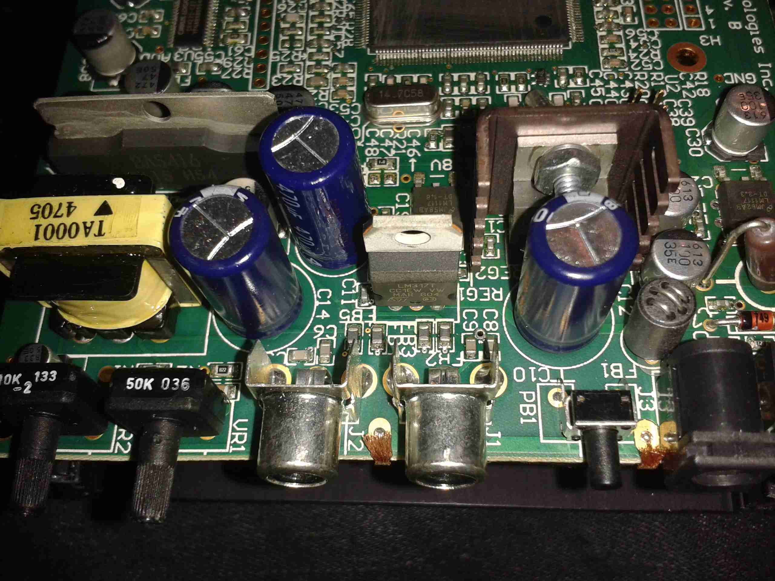
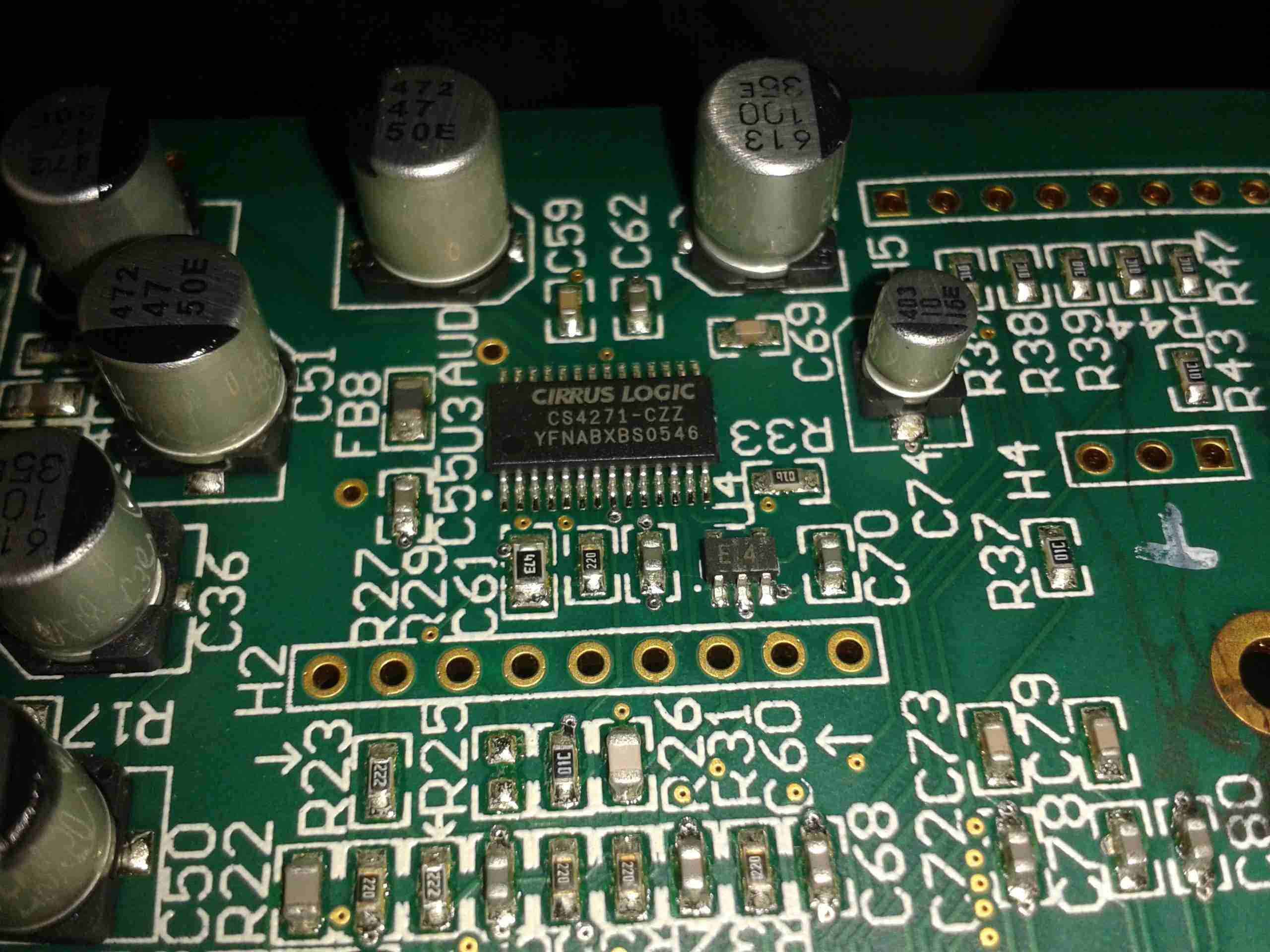
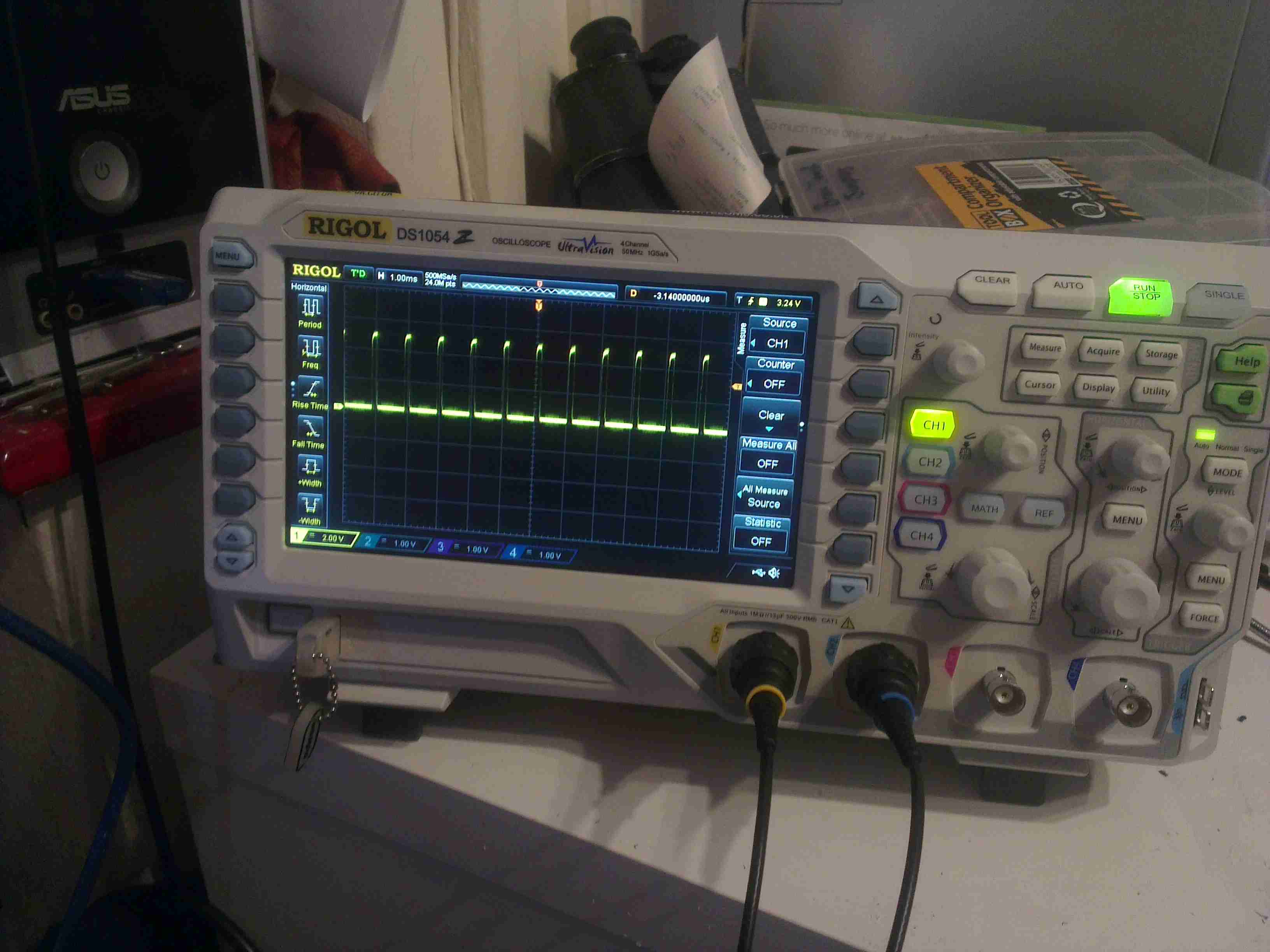


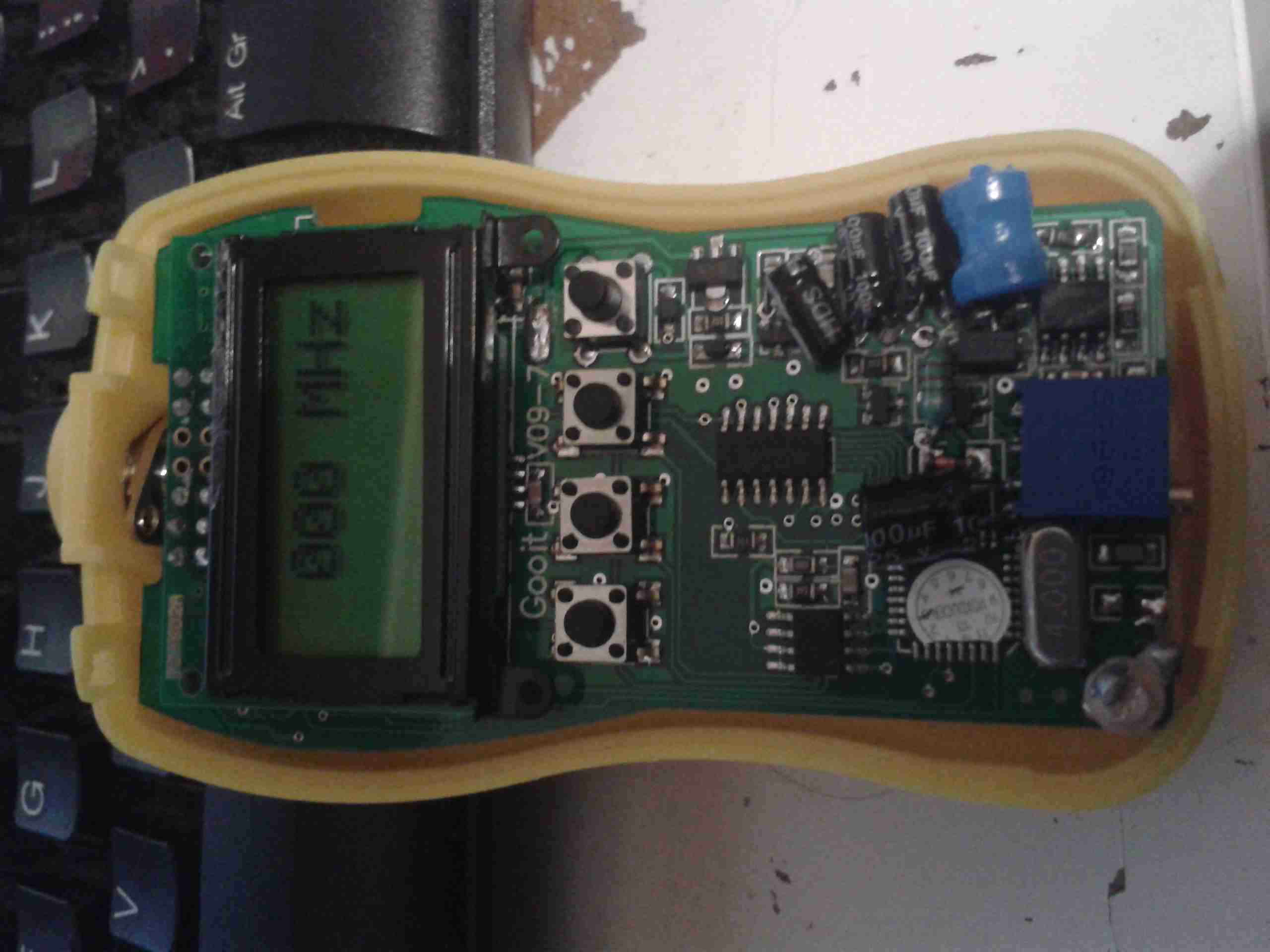
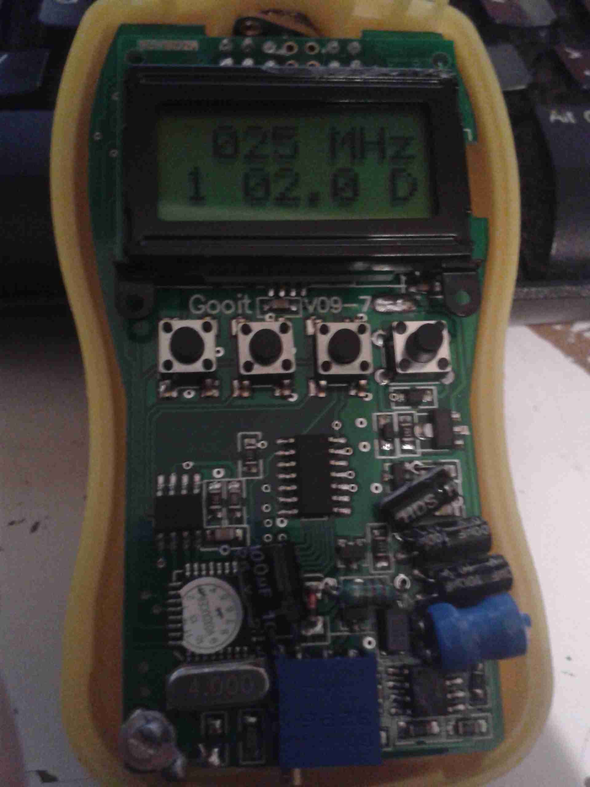
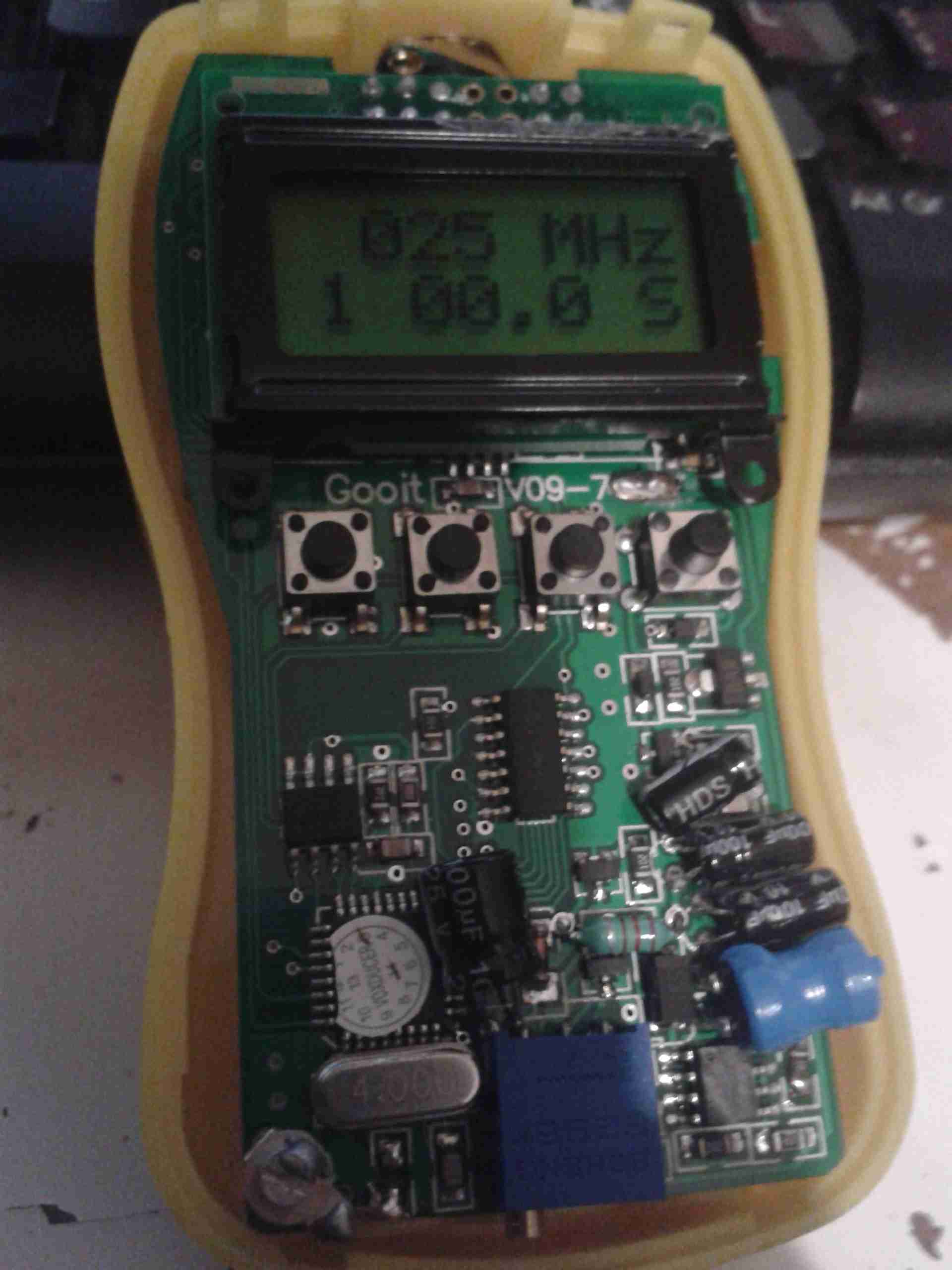
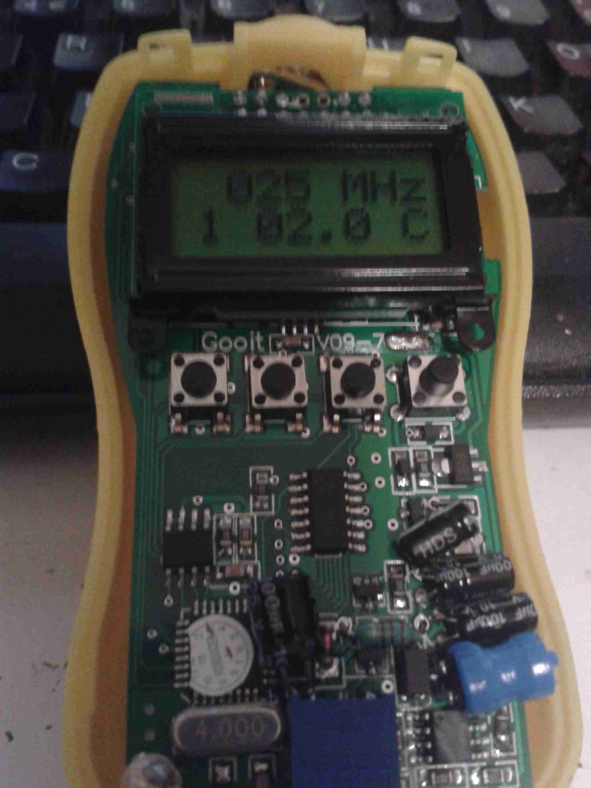
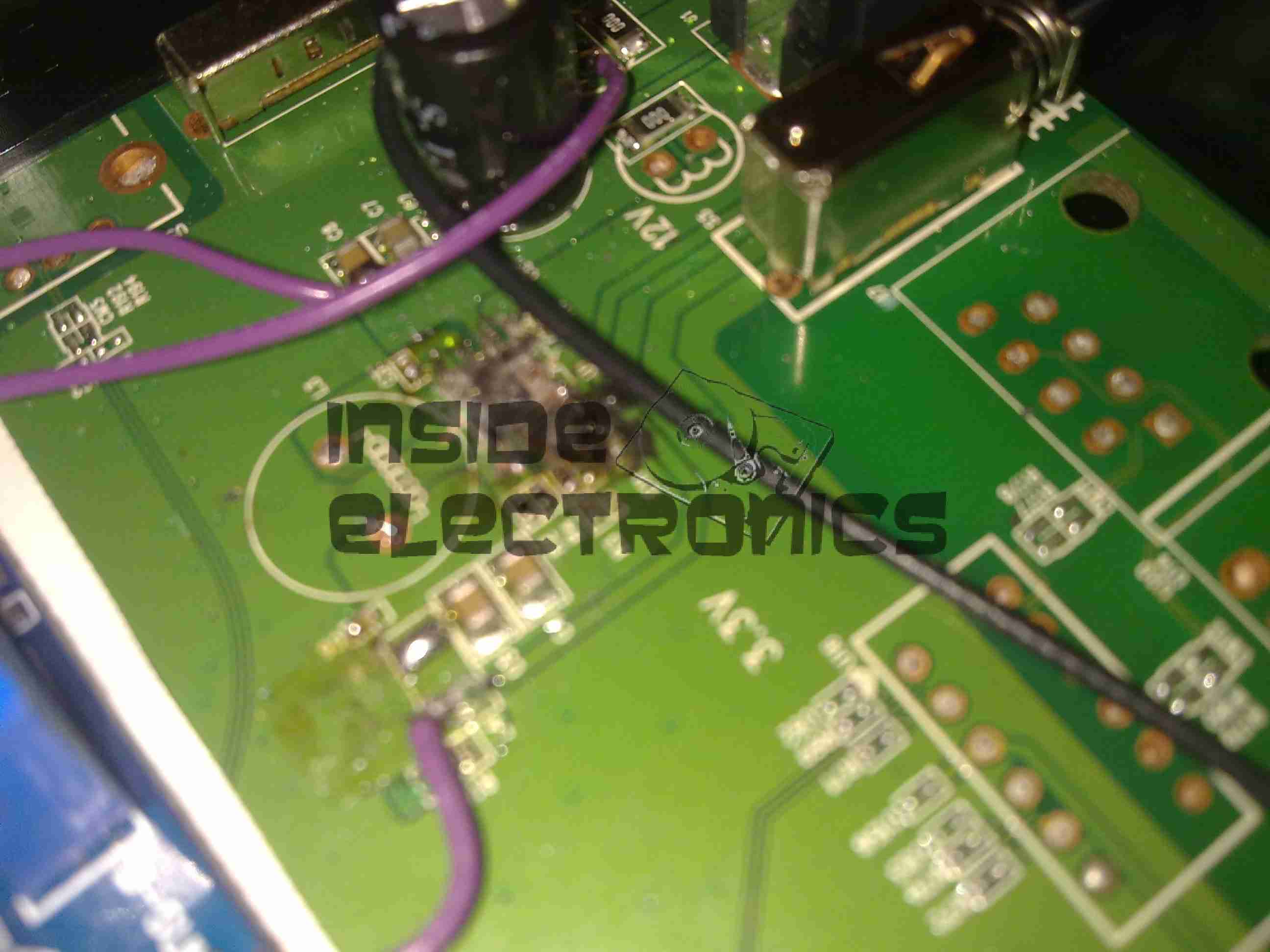
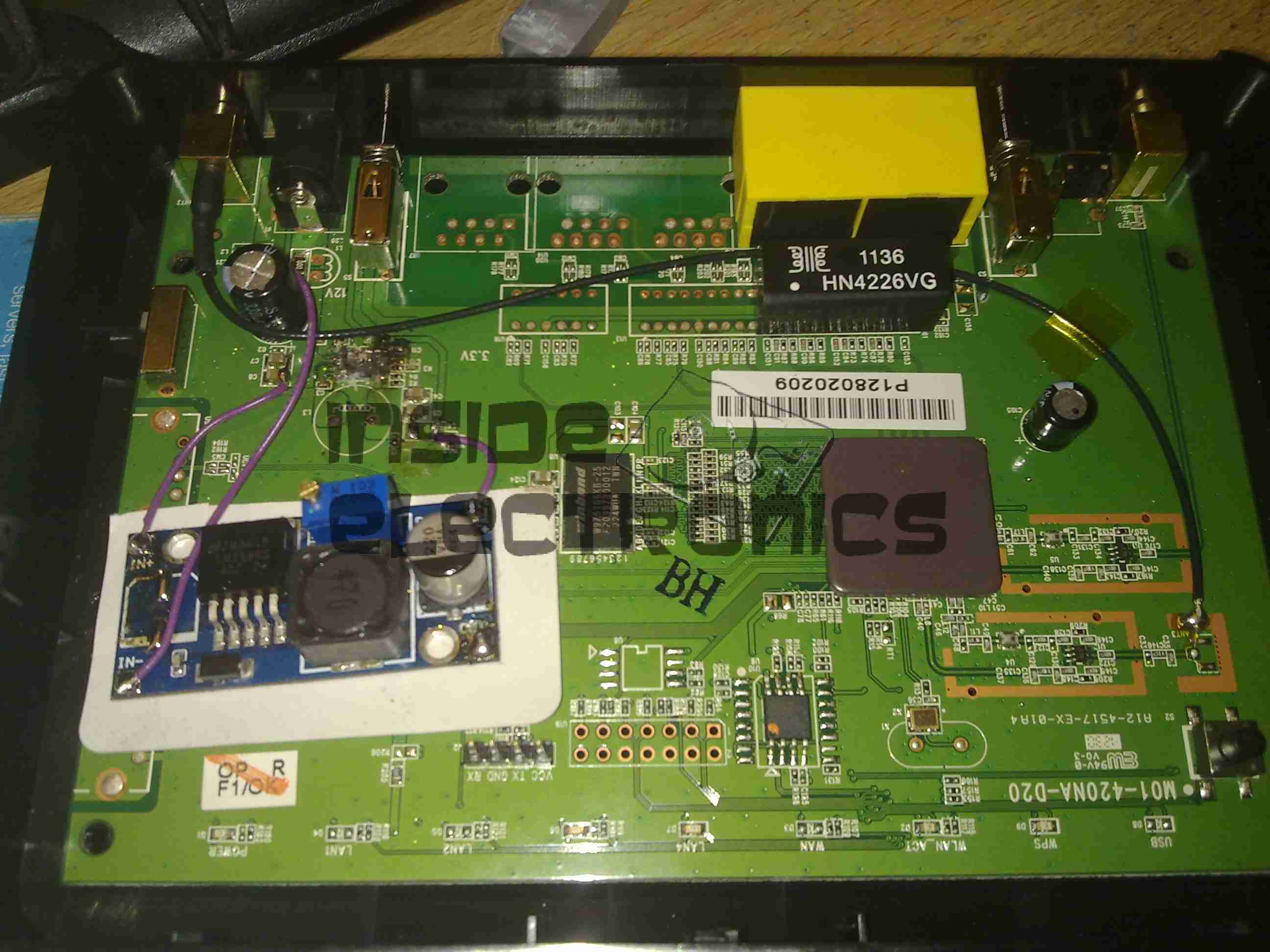
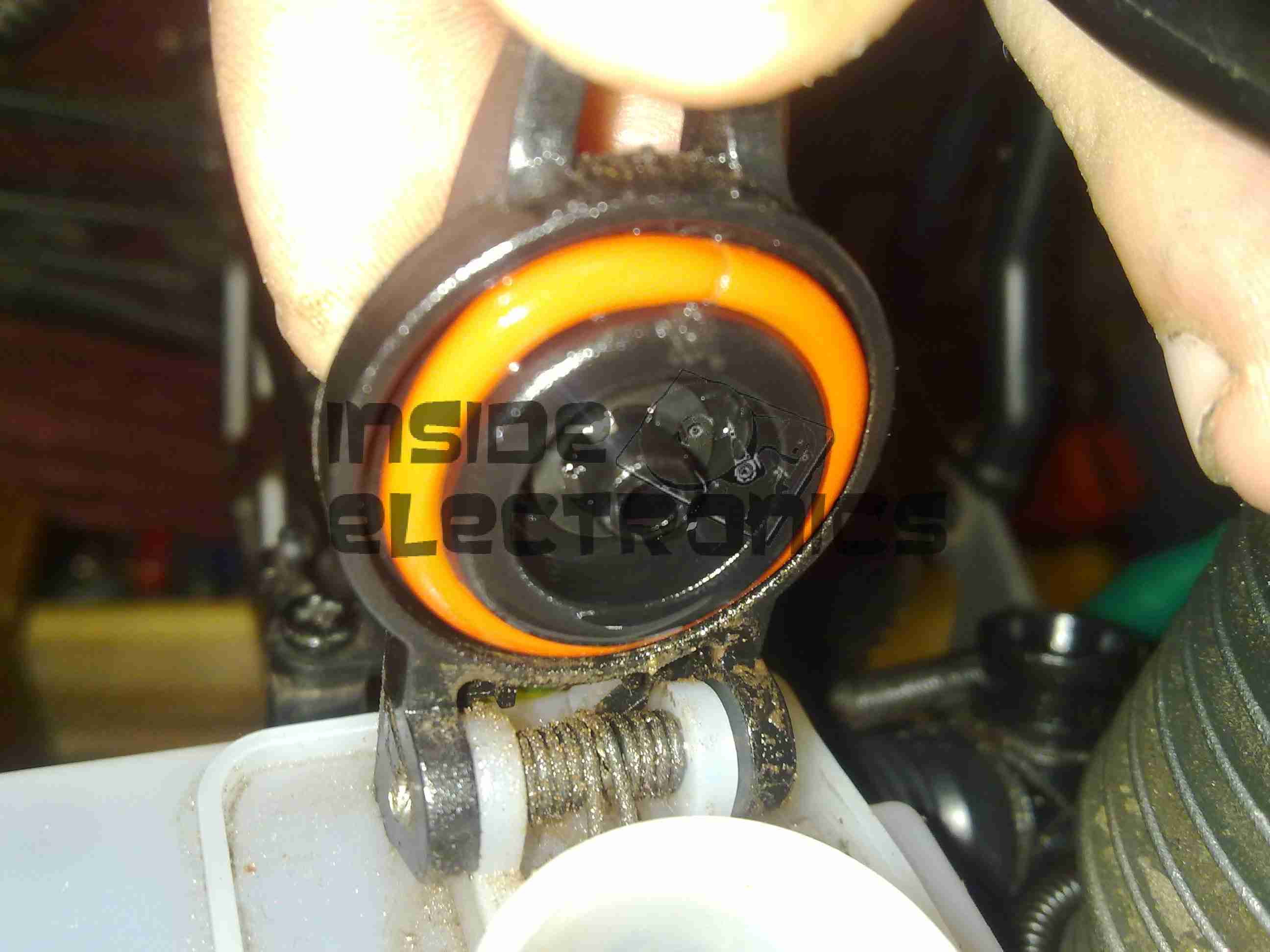
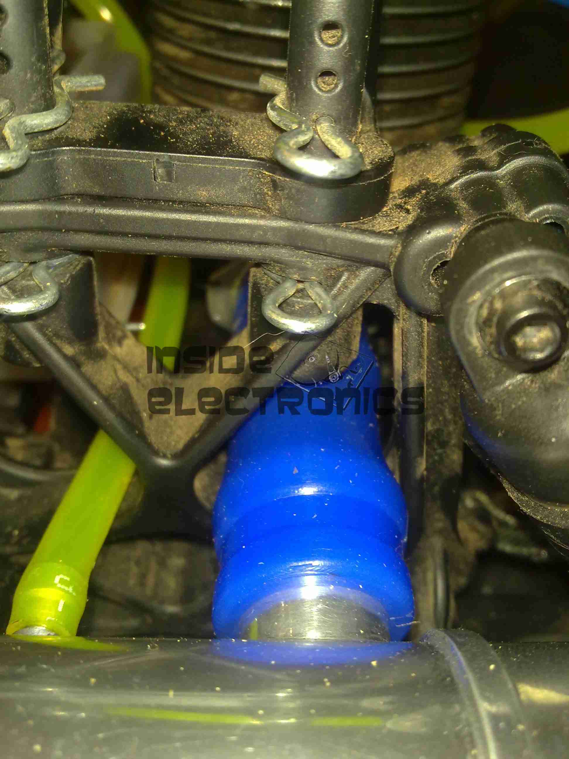
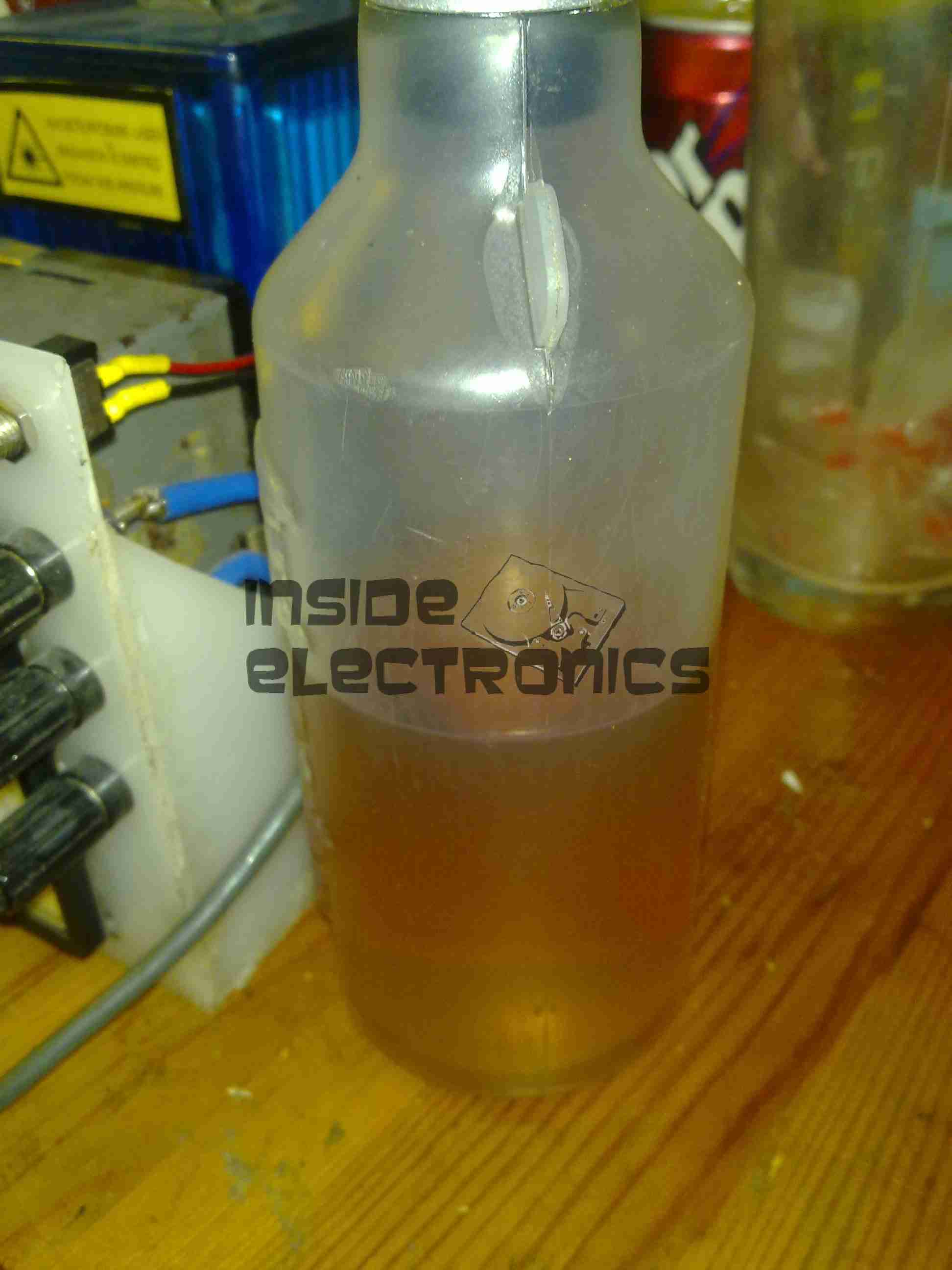

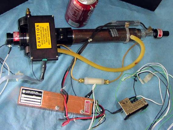
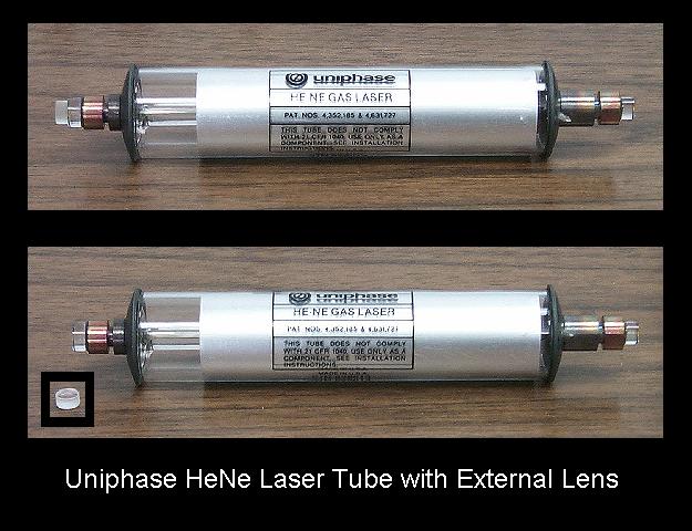