Posted on Leave a comment

Marine Potable Water Management System

LCD Panel
LCD Panel

Having two separate water tanks on nb Tanya Louise, with individual pumps, meant that monitoring water levels in tanks & keeping them topped up without emptying & having to reprime pumps every time was a hassle.
To this end I have designed & built this device, to monitor water usage from the individual tanks & automatically switch over when the tank in use nears empty, alerting the user in the process so the empty tanks can be refilled.

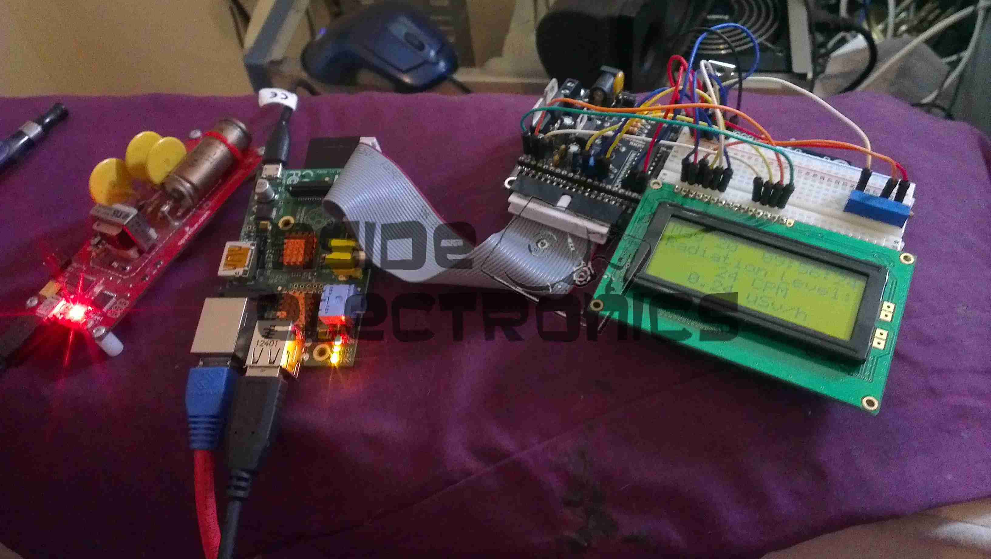
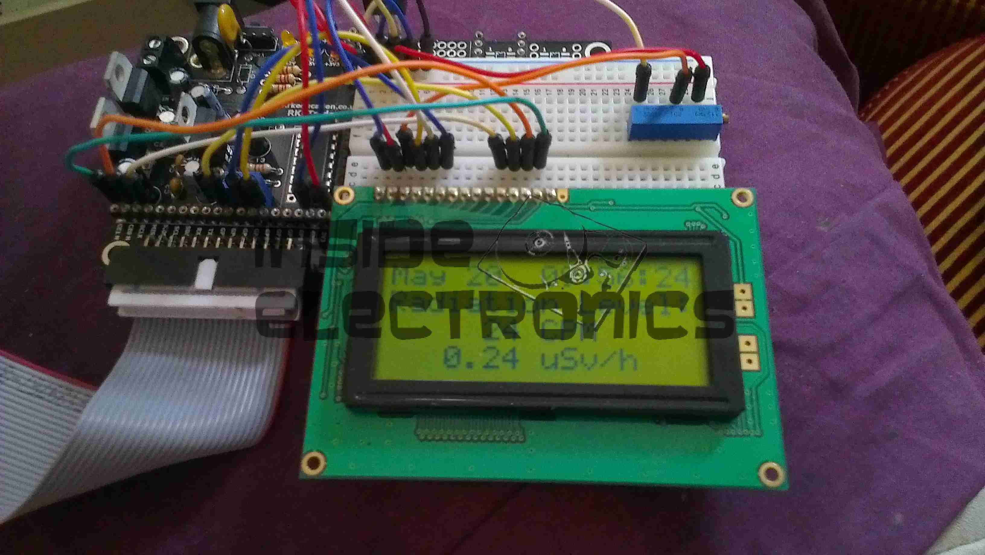
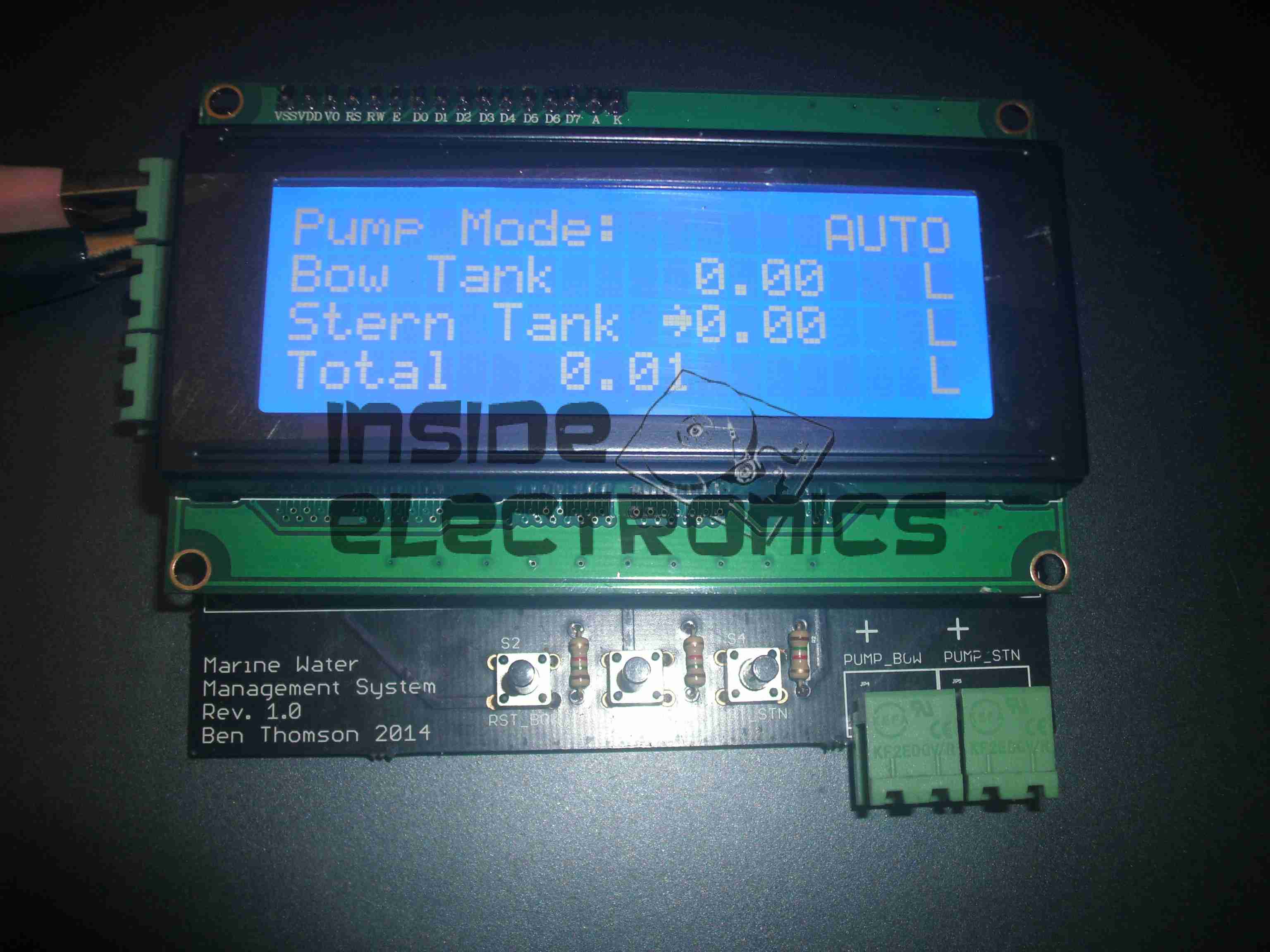
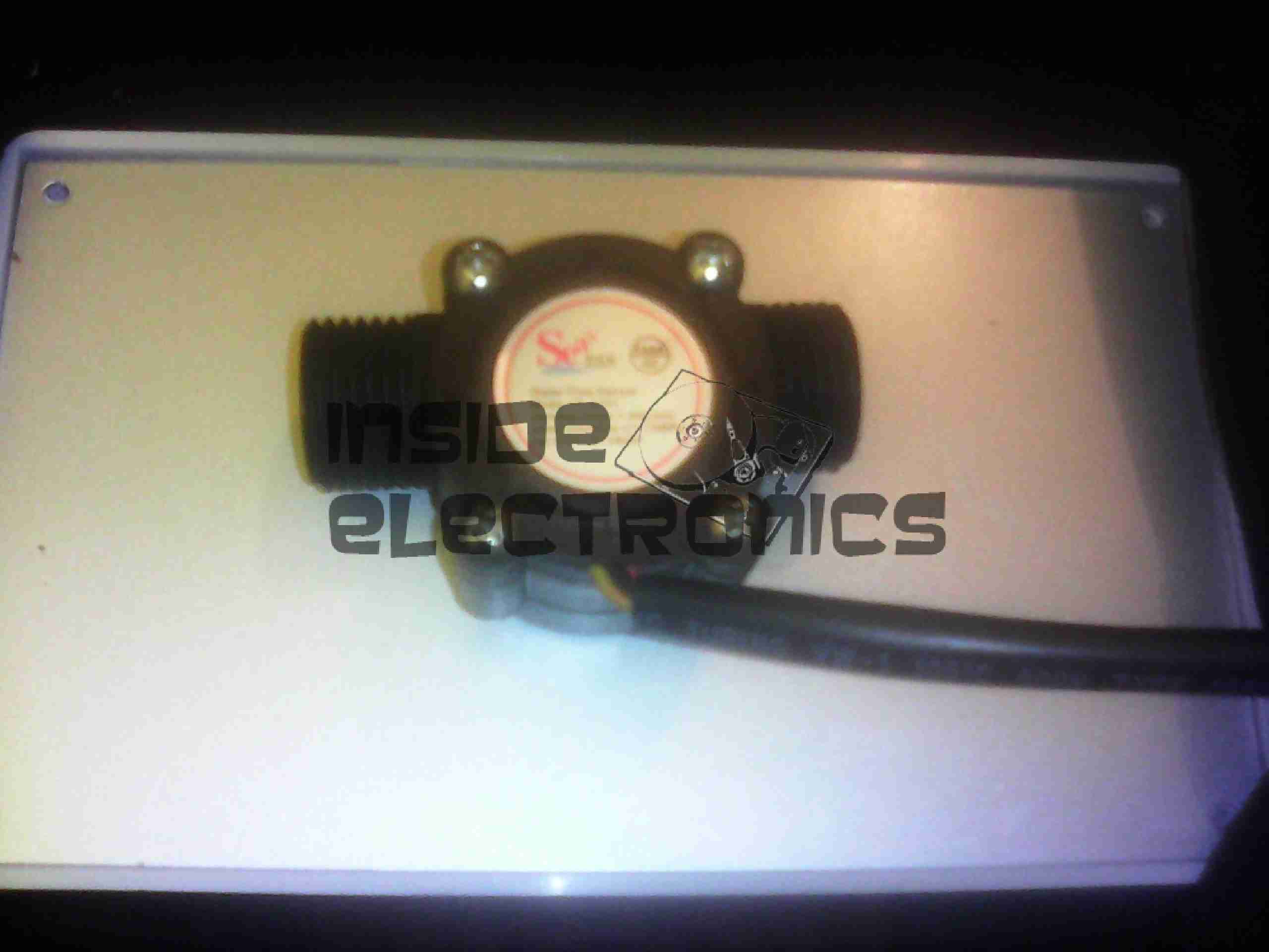
Based around an ATMega328, the unit reads a pair of sensors, fitted into the suction line of each pump from the tanks. The calculated flow is displayed on the 20×4 LCD, & logged to EEPROM, in case of power failure.

Water Flow Sensor
Water Flow Sensor

When the tank in use reaches a preset number of litres flowed, (currently hardcoded, but user input will be implemented soon), the pump is disabled & the other tank pump is enabled. This is also indicated on the display by the arrow to the left of the flow register. Tank switching is alerted by the built in beeper.
It is also possible to manually select a tank to use, & disable automatic operation.
Resetting the individual tank registers is done by a pair of pushbuttons, the total flow register is non-resettable, unless a hard reset is performed to clear the onboard EEPROM.

Main PCB
Main PCB

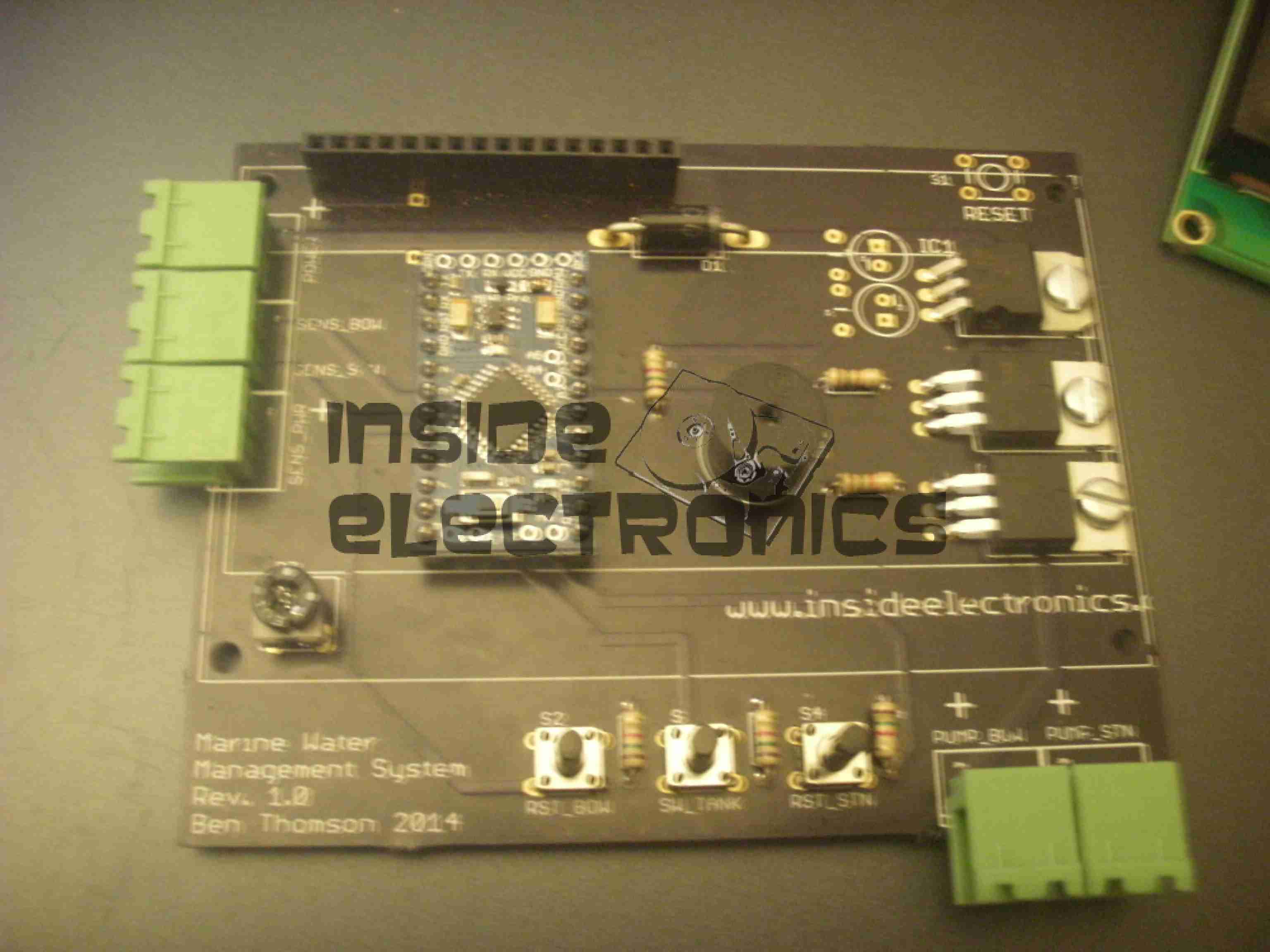
View of the main PCB is above, with the central Arduino Pro Mini module hosting the backend code. 12-24v power input, sensor input & 5v sensor power output is on the connectors on the left, while the pair of pump outputs is on the bottom right, switched by a pair of IRFZ44N logic-level MOSFETS. Onboard 5v power for the logic is provided by the LM7805 top right.

Code & PCB design is still under development, but I will most likely post the design files & Arduino sketch once some more polishing has been done.

Posted on Leave a comment

Raspberry Pi Geiger Counter

Geiger Counter Setup

Here’s my latest project with the Pi: interfacing it with the Sparkfun Geiger counter & outputting the resulting data to a character LCD.

The geiger counter is interfaced with it’s USB port, with the random number generator firmware. A Python script reads from the serial port & every minute outputs CPM & µSv/h data to the display.

The Python code is a mash of a few different projects I found online, for different geiger counters & some of my own customisations & code to write the info to the display & convert CPM into µSv/h.

This also writes all the data into a file at /var/log/radlog.txt

The code for this is below:

import time
import sys
import serial
import os
import RPIO
from RPLCD import CharLCD
from subprocess import * 
from datetime import datetime

# configuration settings

logfile = "/var/log/radlog" # location to save log data
serial_port = "/dev/ttyUSB0"
lcd = CharLCD(pin_rs=15, pin_rw=18, pin_e=16, pins_data=[21, 22, 23, 24], numbering_mode=RPIO.BOARD, cols=16, rows=4, dotsize=10) #Init LCD with physical parameters

f = open(logfile,"a")

ser = serial.Serial(serial_port,9600,timeout=1)

one = 0

#Init LCD with initial values.
lcd.cursor_pos = (0, 1)
lcd.write_string("Geiger Counter")
lcd.cursor_pos = (1, 2)
lcd.write_string("Initializing")
lcd.cursor_pos = (2,-3)
lcd.write_string("Please Wait...")
lcd.cursor_pos = (3, 0)
lcd.write_string(str(0) +" uSv/h")
f.write("Geiger Counter Initialized\n")
f.flush()
while 1==1:
  stamp = int(time.time())
  stamp == round(stamp,0)
  stamp = stamp + 60
  count = 0  
  while 1==1:
      ct = int(time.time())
      ct == round(ct,0)
      if ct > stamp:  break
      #Read from serial port
      bit = ser.read(1)
      if bit != "":
          count = count + 1
          #Conversion of counts per minute to uSv/hr
          usvh = count * 0.01
  at = str(time.asctime())
  t = str(time.time())
  #Write line to log file & print info to console
  f.write("["+at+"."+t+"] "+str(count) + " CPM " +str(usvh) + " uSv/h\n")
  f.flush()
  print "["+at+"."+t+"] Count "+str(count) + " " + str(usvh) +" uSv/hr"
  #Send measurement info to LCD
  lcd.clear()
  lcd.cursor_pos = (0, 0)
  lcd.write_string(datetime.now().strftime('%b %d  %H:%M:%S\n'))
  lcd.cursor_pos = (1, 0)
  lcd.write_string("Radiation Level:")
  lcd.cursor_pos = (2, 1)
  lcd.write_string(str(count) +" CPM")
  lcd.cursor_pos = (3, -1)
  lcd.write_string(str(usvh) +" uSv/h")
Info Display
Info Display
Posted on Leave a comment

Safe 4 Tumbler Combination Lock

Combination Lock
Combination Lock
Combination Lock

Just a very quick post with some images of an industrial safe combination lock.

Tumblers Aligned
Tumblers Aligned

Here the tumblers are lined up to allow the lock to open.

Bolt Locked
Bolt Locked

The locking bar has dropped into the slots in the tumbler plates & engaged with the cam.

Bolt Unlocked
Bolt Unlocked

Rotating the cam pulls the bolt into the lock, allowing the door to open.

Unlocked
Unlocked

The dial screws into the cam plate to allow the mechanism to be operated.

Posted on 1 Comment

MSR605 3-Track Magnetic Stripe Writer

MSR605
MSR605

This unit was bought from eBay to experiment with Magnetic Stripe cards, for little money. This unit is capable of reading & writing all 3 tracks, & both Hi-Co & Lo-Co card types.
Interfaced to a PC through USB, this has a built in PL2303 USB-Serial IC & requires 3A at 9v DC to operate.
The 3 Indicator LEDs on the top of the unit can be toggled by the included software for Power/OK/Fault condition signalling.

Unit Bottom
Unit Bottom

Bottom of the unit with the model labels.

Model Label
Model Label

Closeup of the model label & serial number.

PCB Bottom
PCB Bottom

Here the bottom cover has been removed, showing the main PCB. The pair of large ICs bottom center interface with the magnetic heads. The IC above them has had the markings sanded off.

USB-Serial Interface

Closeup of the Prolific PL-2303 USB-Serial converter IC.

PCB Top
PCB Top

Here the connections to the R/W heads are visible, current limiting resistors at the left for the write head, a pair of signal relays, a pair of optoisolators & a LM7805 linear voltage regulator.

LEDs
LEDs

Here is the trio of indicator LEDs on a small sub-board.

Frame Bottom
Frame Bottom

The PCB has been removed from the main frame here, the only component visible is the rotary encoder.

Rotary Encoder
Rotary Encoder

The rotary encoder has a rubber wheel fitted, which reads the speed of the card as it is being swiped for writing. This allows the control logic to write the data to the stripe at the correct rate for the speed of the card. This allows the unit to write cards from 5-50 inches per second speed.
The Write head is directly behind the rubber pressure roller.

Read/Write Heads
Read/Write Heads

Here you can see the R/W head assembly. The write head is on the right, read on the left. When a card is written to, it immediately gets read by the second head for verification.

The drivers for this unit are also available here: Magcard Writer Drivers

Posted on Leave a comment

USB Multi Card Reader

Card Reader
Card Reader

Here is a cheap USB 8-in-1 card reader. Power & Access LEDs are on top left.

PCB Top
PCB Top

Top of the PCB. The OTi IC is the interface IC to the USB port, part number is OTI002126. Card sockets on the top here are CF/Microdrive & Memory Stick.

PCB Bottom
PCB Bottom

Bottom of the PCB with the SD/MMC, Smart Media

Posted on Leave a comment

Southwestern Bell Freedom Phone

Phone
Phone

This is an old cordless landline phone, with dead handset batteries.

Handset Radio Board
Handset Radio Board

Here’s the handset with the back removed. Shown is the radio TX/RX board, underneath is the keyboard PCB with the speaker & mic. All the FM radio tuning coils are visible & a LT450GW electromechanical filter.

Handset Radio Board Bottom

Radio PCB removed from the housing showing the main CPU controlling the unit, a Motorola MC13109FB.

Keypad Board
Keypad Board

The keypad PCB, with also holds the microphone & speaker.

Handset Keypad Board Bottom

Bottom of the keypad board, which holds a LSC526534DW 8-Bit µC & a AT93C46R serial EEPROM for phone number storage.

Base Main Board
Base Main Board

Here’s the base unit with it’s top cover removed. Black square object on far right of image is the microphone for intercom use, power supply section is top left, phone interface bottom left, FM radio is centre. Battery snap for power backup is bottom right.

Power Supply Section

PSU section of the board on the left here, 9v AC input socket at the bottom, with bridge rectifier diodes & main filter capacitor above. Two green transformers on the right are for audio impedance matching. Another LT450GW filter is visible at the top, part of the base unit FM transceiver.

ICs
ICs

Another 8-bit µC, this time a LSC526535P, paired with another AT93C46 EEPROM. Blue blob is 3.58MHz crystal resonator for the MCU clock. The SEC IC is a KS58015 4-bit binary to DTMF dialer IC. This is controlled by the µC.

Base Main Board Bottom

Underside of the base unit Main PCB, showing the matching MC13109FB IC for the radio functions.

Posted on Leave a comment

Ericsson GA628

Front
Front

Here is a phone from the mid 90s, the Ericsson GA628. Here visible is the front of the unit with keypad, & single line monochrome LCD for number display.

Battery & Rear
Battery & Rear

Here the battery is removed from the phone, showing the SIM card socket. At the top under the antenna stub is the socket for an external antenna.

Front Removed
Front Removed

Here the front is removed from the phone, PCB on left, rear of keypad on right. Microphone is at bottom of keypad, with speaker at the top. Top right of the PCB is the ringer buzzer, left is shield for RF amplifier.

Main PCB
Main PCB

Here is the back of the main PCB, RF sections on left & centre. Processing & memory on right.

Battery
Battery

This phone had a Ni-Mh battery, before Li-Ion batteries were introduced.

LCD
LCD

The LCD from the front of the phone is shown here. A simple dot matrix single line unit.