Since I’ve been working on the backend servers a lot over the past few days, I’ve decided it was time to get some broken things on the blog fixed.
Firstly, the radiation monitor graphs. Originally I was using a Raspberry Pi to grab the data from the local monitor, and that was connecting via FTP to the server over in the datacentre to push it’s graph images. Since the server is now on the same local network as the monitor, there’s no need to faff about with FTP servers, so I’ve rejigged things with some perl scripts from cristianst85 over on GitHub, running on the web server itself.
I deviated from the suggested place to put the scripts on the server & opted to store everything within the Experimental Engineering hosting space, so it gets backed up at the same time as everything else on a nightly basis.
powered by Advanced iFrame
This is also accessible from the menu at top left, the script pulls data from the monitor & updates the images every 60 seconds via a cron job.
I’ve removed a couple of dead pages from the blog system, along with some backend tidying of the filesystem. Over the years things have gotten quite messy behind the scenes. This blog is actually getting quite large on disk, I’ve hit the 15GB mark, not including the database!
Caching is enabled for all posts on the blog now, this should help speed things up for repeat visitors, but as most of my content is (large) image based, this might be of limited help. I’m currently tuning the MySQL server for the load conditions, but this takes time, as every time I change some configuration settings I have to watch how things go for a few days, before tweaking some more.
Server Control Panels – More Of The Same
Sorry Sentora. I tried, and failed to convert over to using it as my new server control panel. Unfortunately it just doesn’t give me the same level of control over my systems, so I’ll be sticking with Virtualmin for the foreseeable future. Sentora stores everything in, (to me at least), very odd places under /var/ and gave me some odd results with “www.” versions of websites – some www. hosts would work fine, others wouldn’t at all & just redirect to the Sentora login interface instead. This wasn’t consistient between hosting accounts either, and since I didn’t have much time to get the migration underway, this problem was the main nail in the coffin.
Just storing everything under the sun in /var/ makes life a bit more awkward with the base CentOS install, as it allocates very little space to / by default, (no separate /var partition in default CentOS), giving most of the disk space to /home. Virtualmin on the other hand, stores website public files & Maildirs under /home, saving /var for MySQL databases & misc stuff.
The backup system provided is also utterly useless, there’s no restore function at all, and just piles everything in the account into a single archive. By comparison, Virtualmin has a very comprehensive backup system built in, that supports total automation of the process, along with full automatic restore functionality for when it’s needed.
Sentora did have some good points though:
It handled E-Mail logins & mail filters much more gracefully than Virtualmin does, and comes with Roundcube already built into the interface ready to use. With Virtualmin the options are to use the Usermin side of the system for E-Mail, which I find utterly awful to use, or install a webmail client under one of the hosted domains (my personal choice).
Mail filtering is taken care of with Sieve under Sentora, while Procmail does the job under Virtualmin.
Sentora does have a nicer, simpler, more friendly interface, but it hides most of the low-level system stuff away, while under Virtualmin *everything* on the system is accessible, and it provides control interfaces for all the common server daemons.
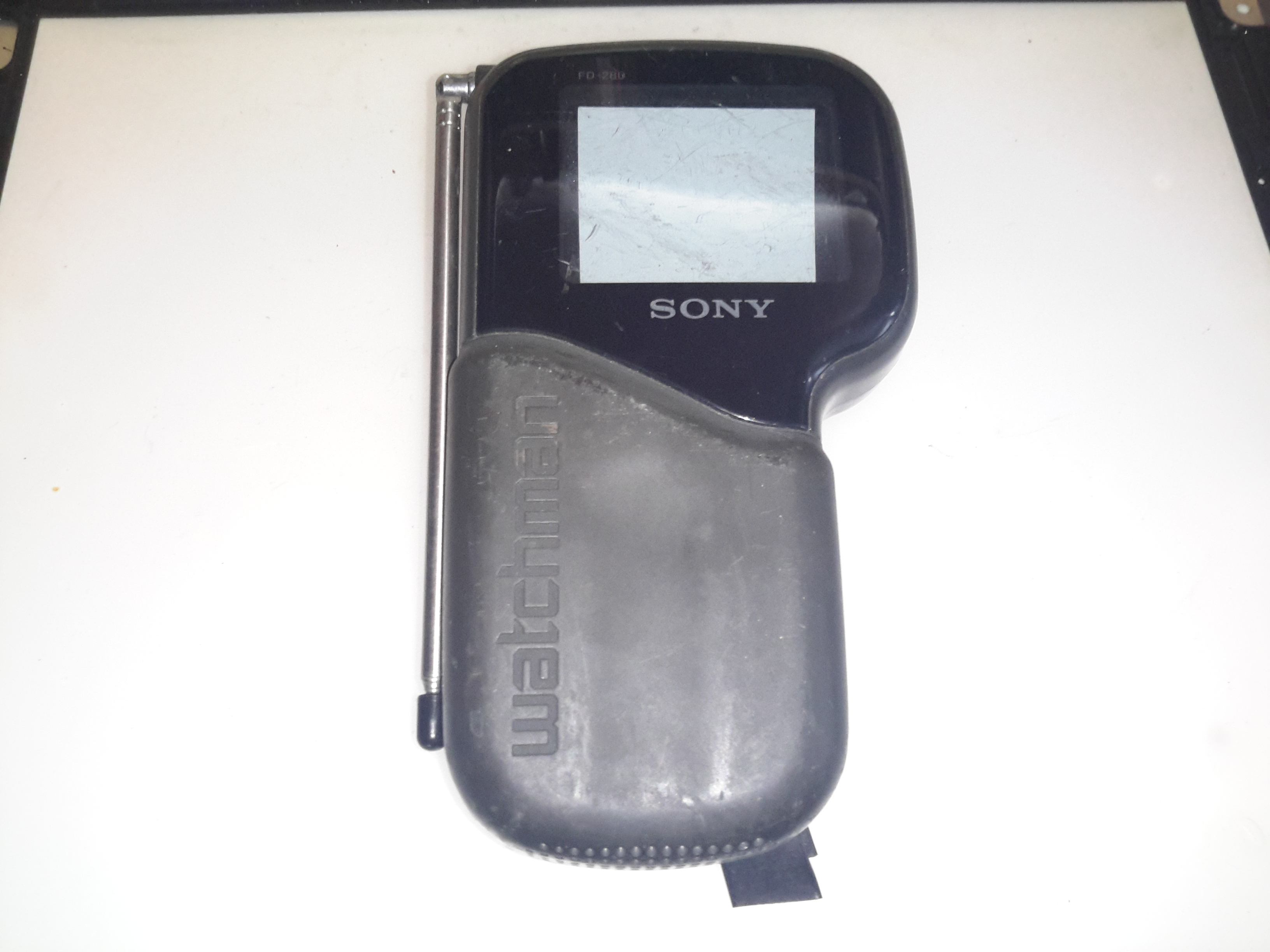
Here’s another Sony Flat CRT TV, the FD0280. This one was apparently the last to use CRT technology, later devices were LCD based. This one certainly doesn’t feel as well made as the last one, with no metal parts at all in the frame, just moulded plastic.
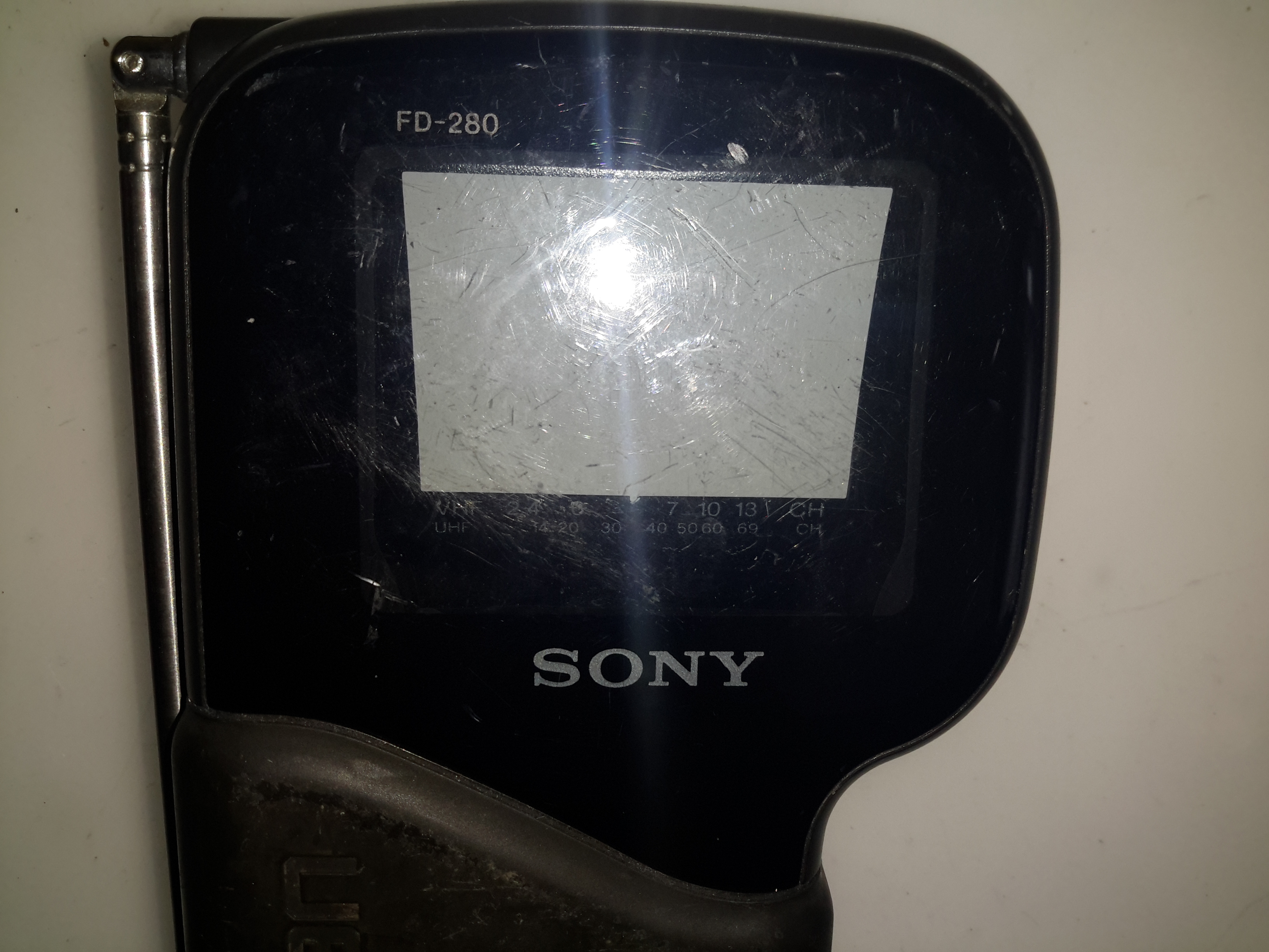
CRT Screen
Being a later model, this one has a much larger screen.
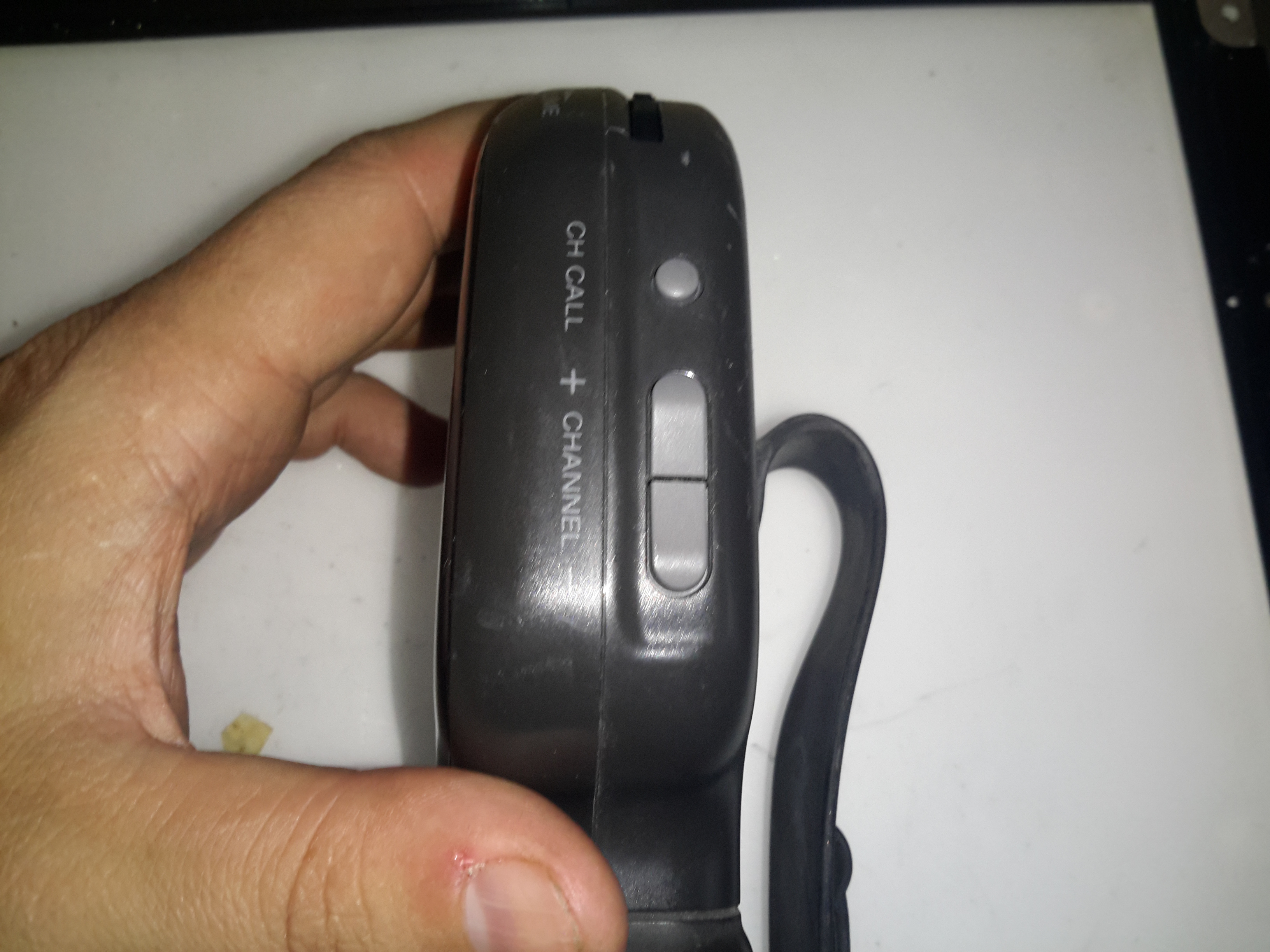
Autotuning
Instead of the manual tuner of the last Watchman, this one has automatic tuning control, to find the local stations.
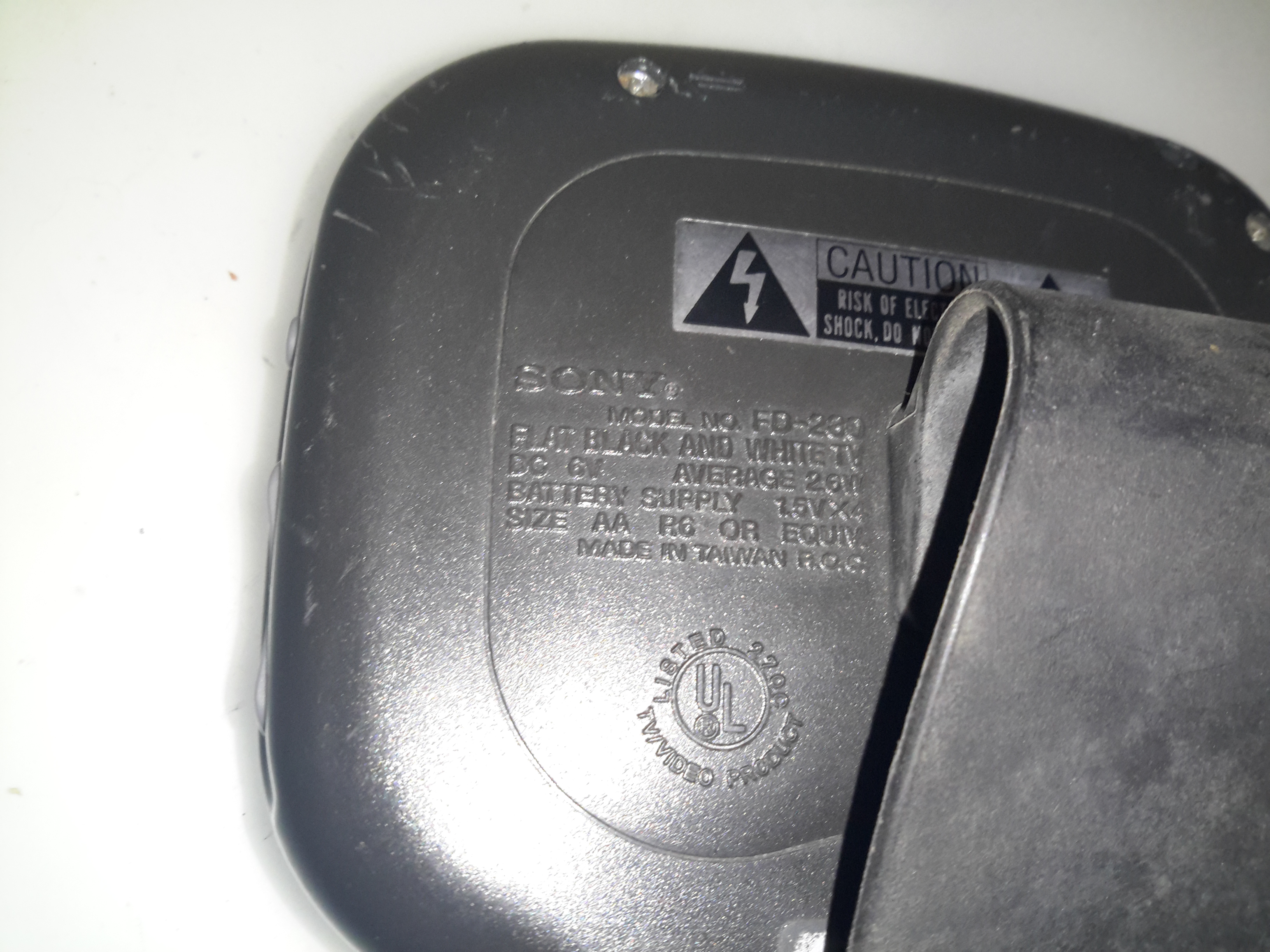
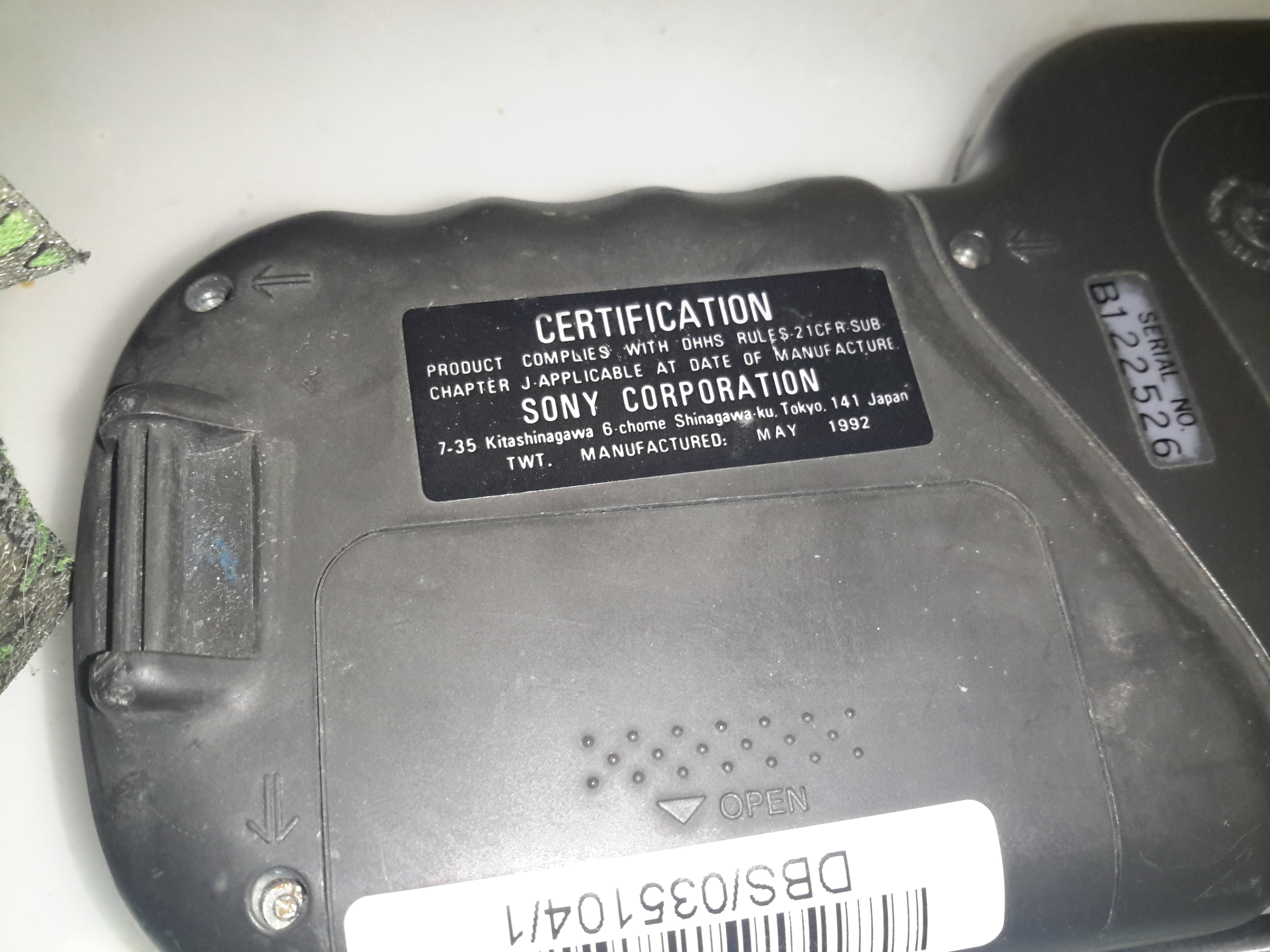
Spec Label
The spec puts the power consumption a little higher than the older TV, this isn’t surprising as the CRT screen is bigger & will require higher voltages on the electrodes.
Certification Label
The certification label dates this model to May 1992.
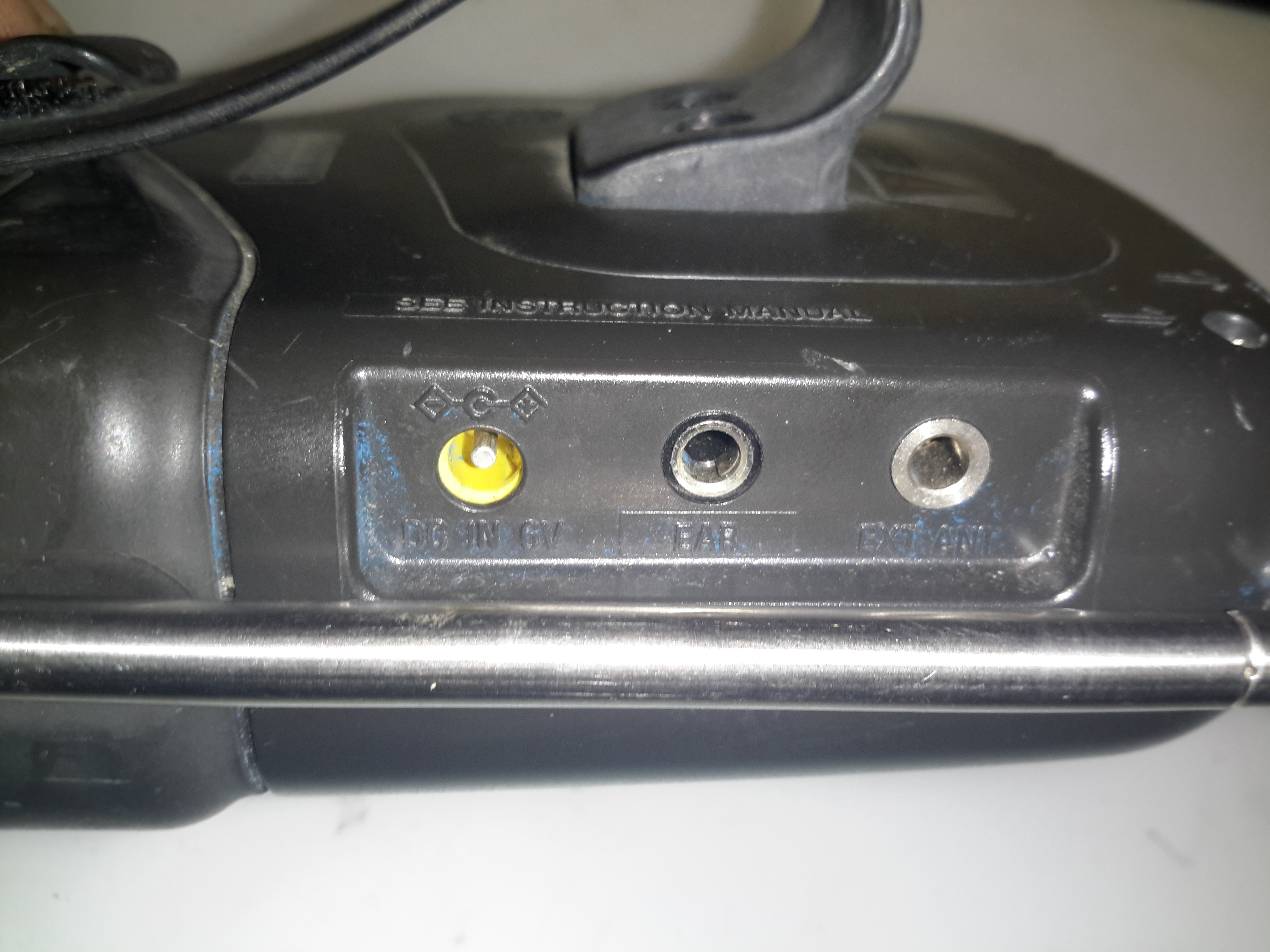
External Inputs
Still not much in the way of inputs on this TV. There’s an external power input, external antenna input & a headphone jack. No composite from the factory. (Hack incoming ;)).
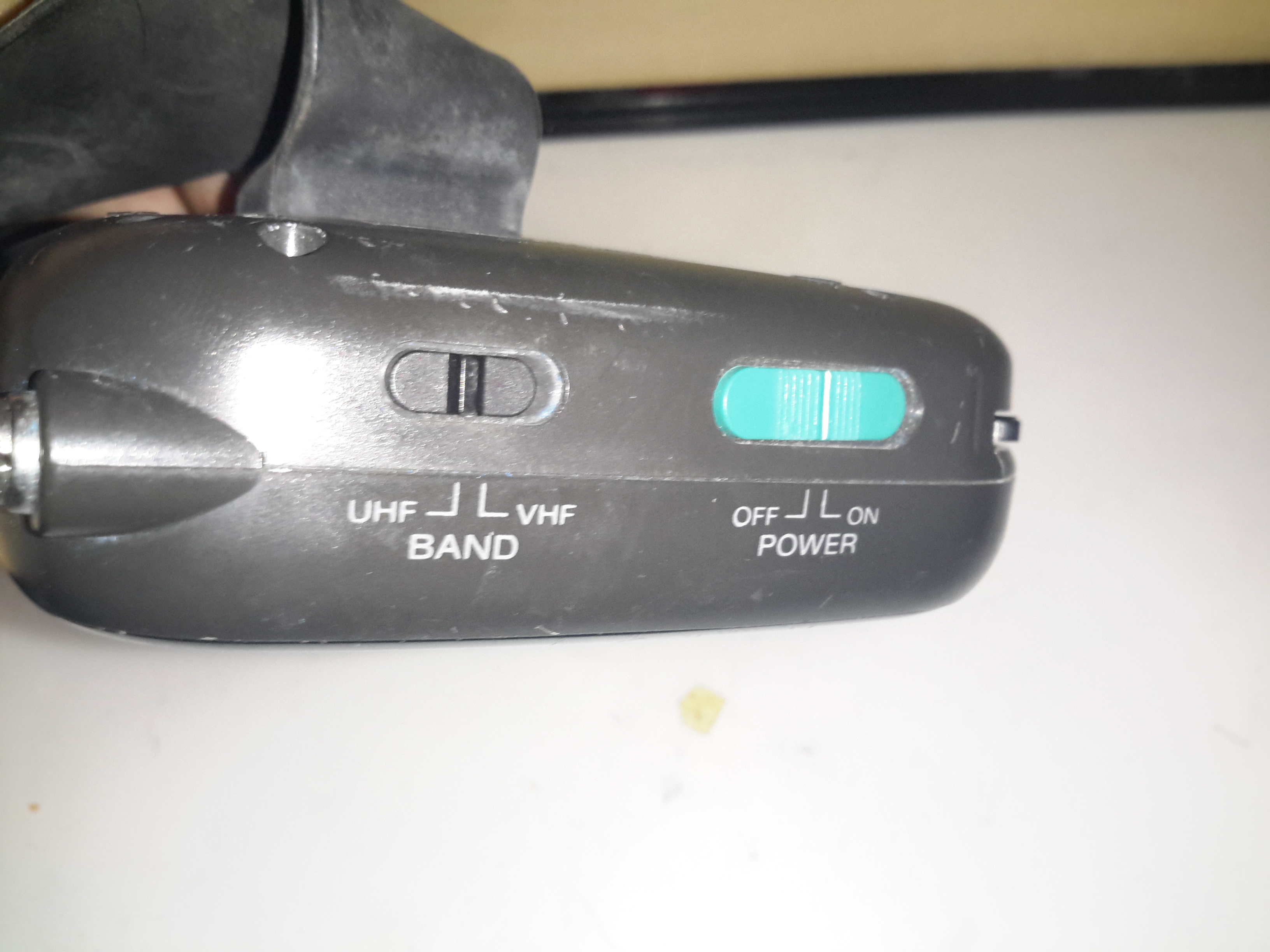
Power / Band
The UHF/VHF & power switches are on the top of this model.
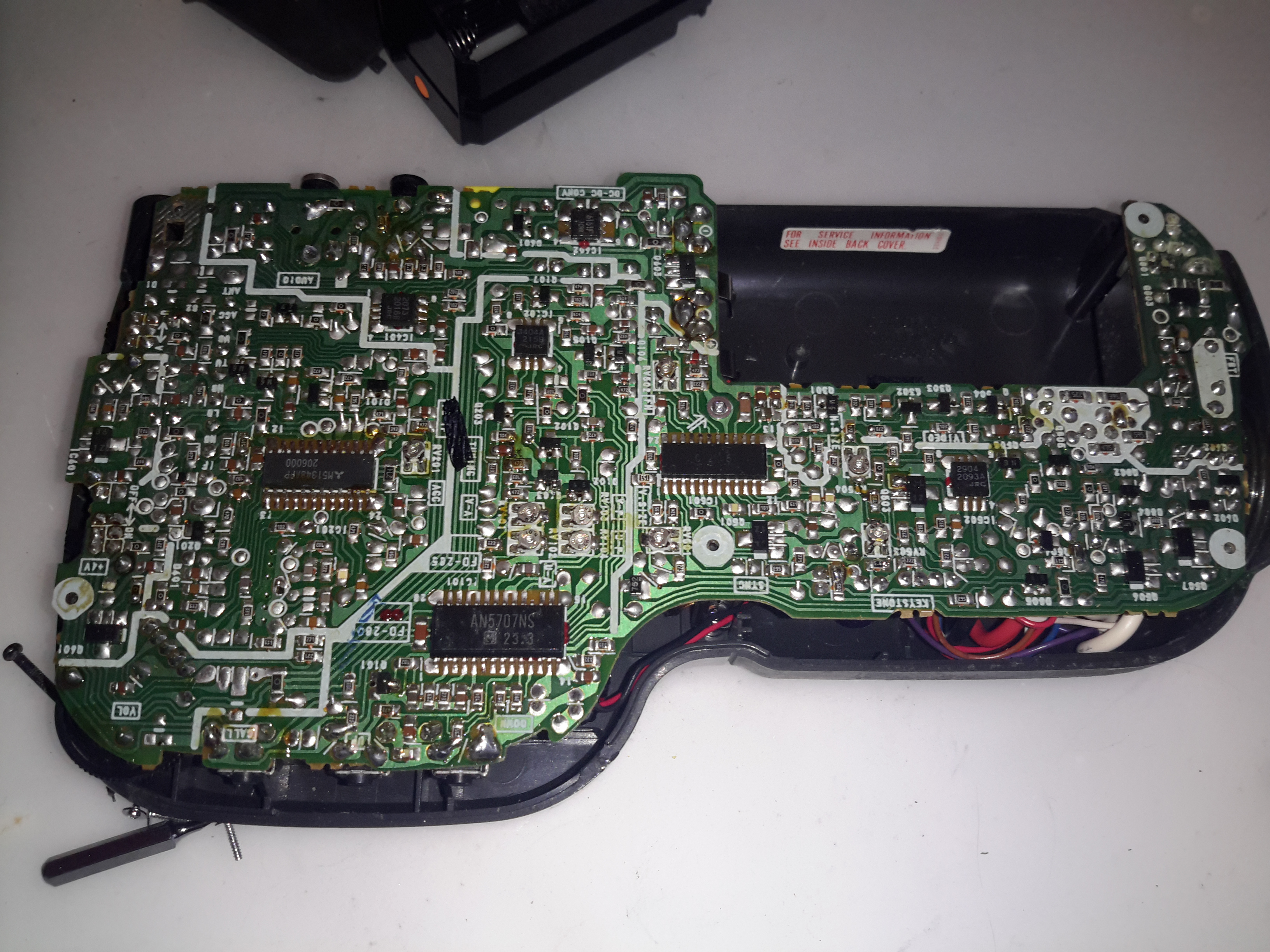
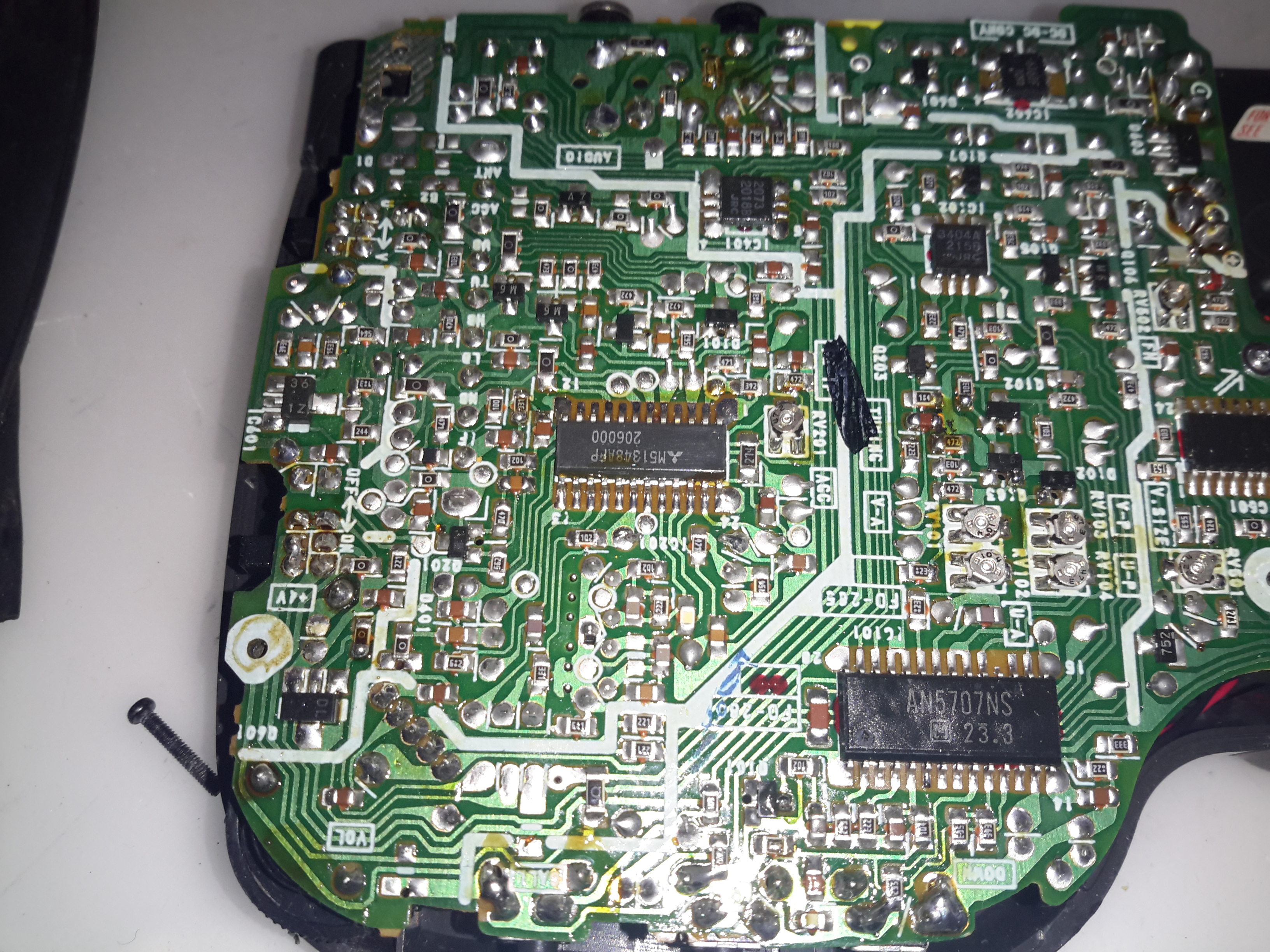
Back Cover Removed
Removing some very tiny screws allows the back to be removed. There’s significant difference in this model to the last, more of the electronics are integrated into ICs, nearly everything is SMD.
RF Section
There’s the usual RF tuner section & IF, in this case the VIF/SIF is a Mitsubishi M51348AFP.
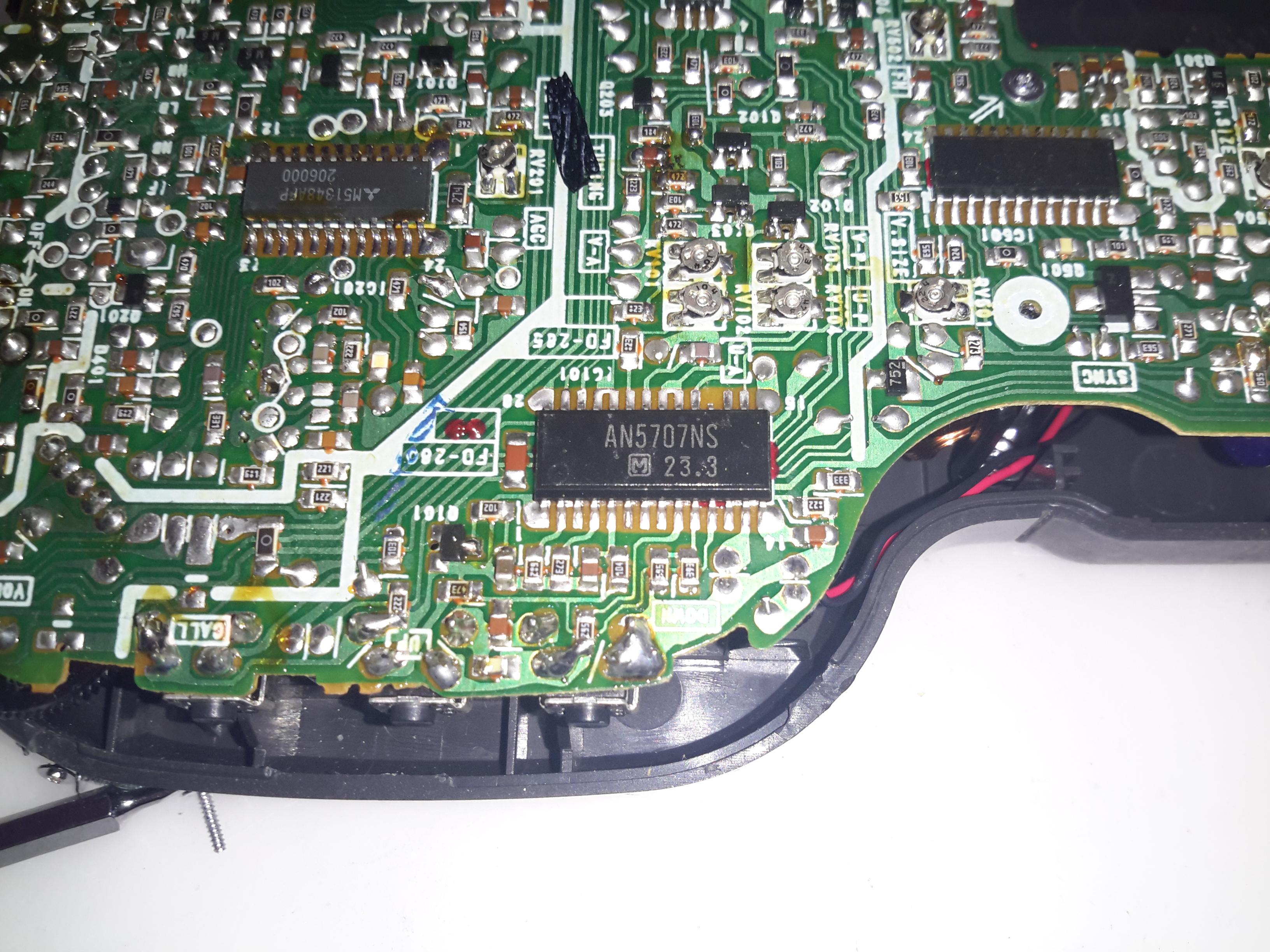
Tuner Controller
The digital control of the tuner is perfomed by this Panasonic AN5707NS.
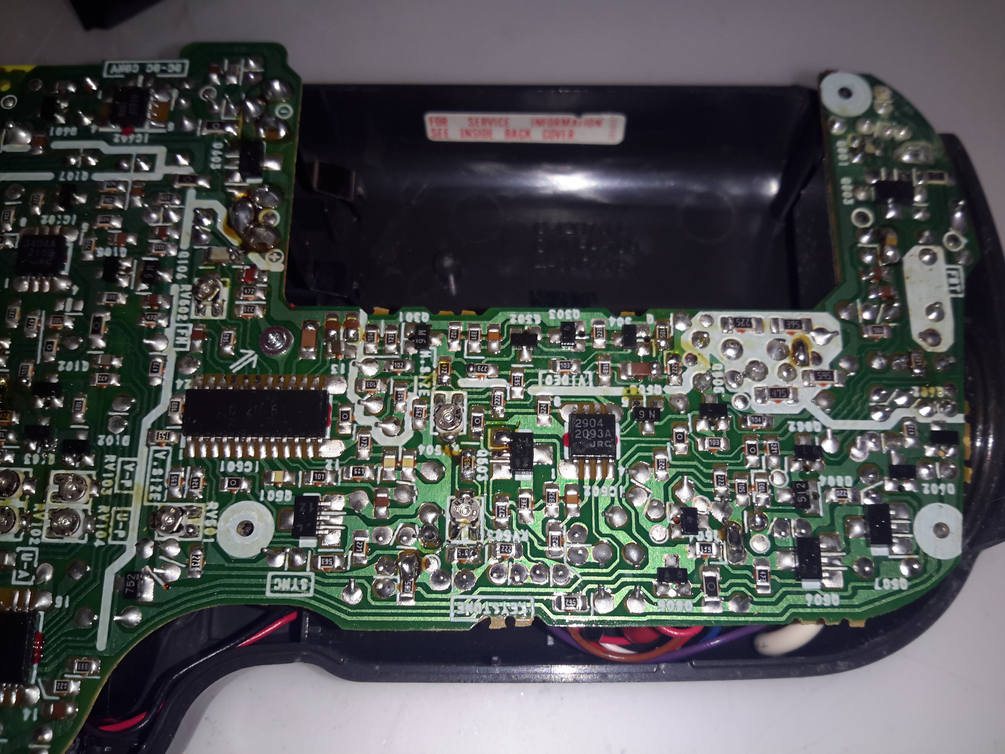
Deflection / Sync
The deflection & sync functions appear to be controlled by a single Sony branded custom IC, the CX20157. Similar to many other custom Sony ICs, a datasheet for this wasn’t forthcoming.
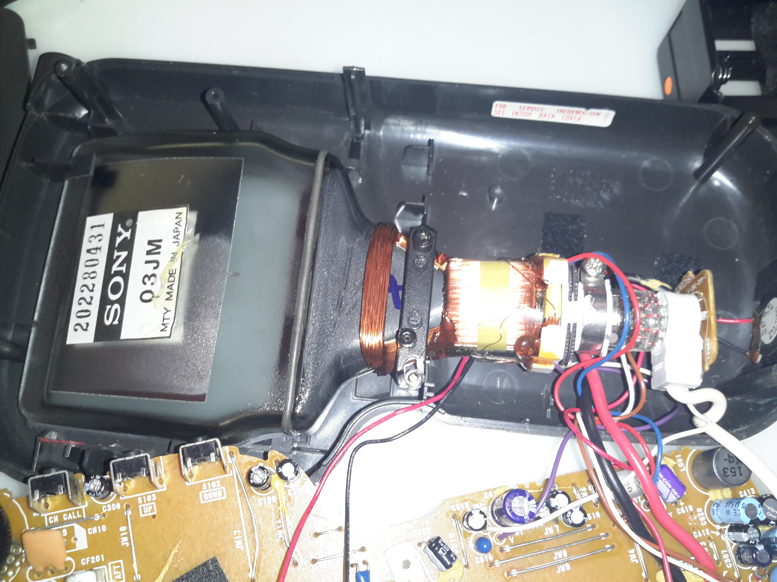
PCB Top
There’s very little on the top side of the board, the RF section is on the left, there’s a DC-DC converter bottom centre next to the battery contacts. This DC-DC converter has a very unusual inductor, completely encased in a metal can. This is probably done to prevent the magnetic field from interfering with the CRT.
CRT
Here’s the CRT itself, the Sony 03-JM. The back of this CRT is uncoated at the bottom, the tuning scale was taped to the back so it lined up with the tuning bar displayed on the screen.
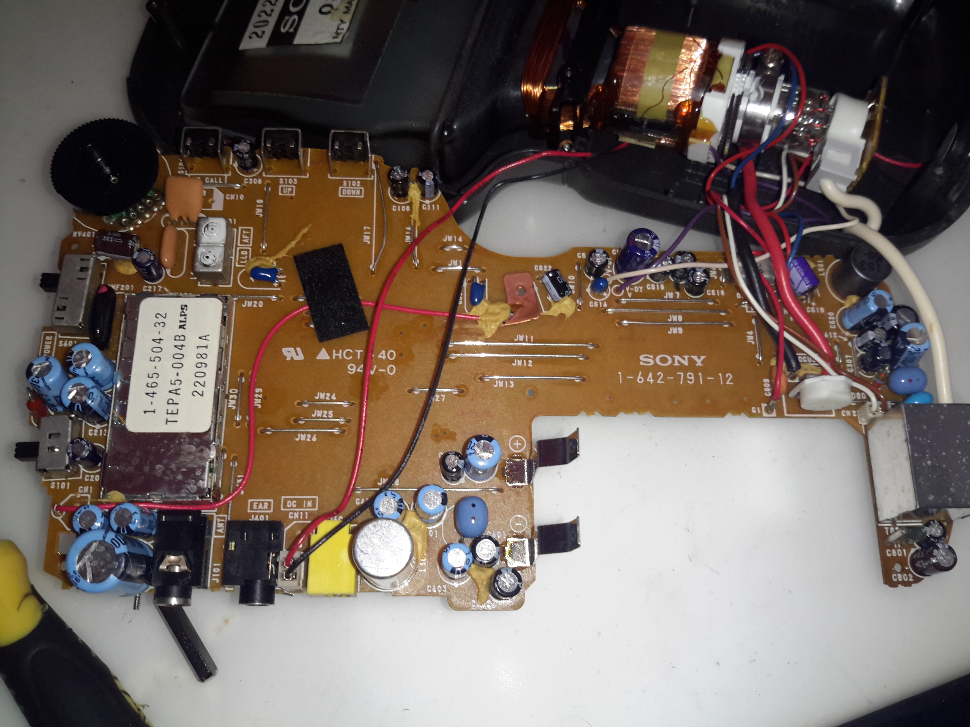
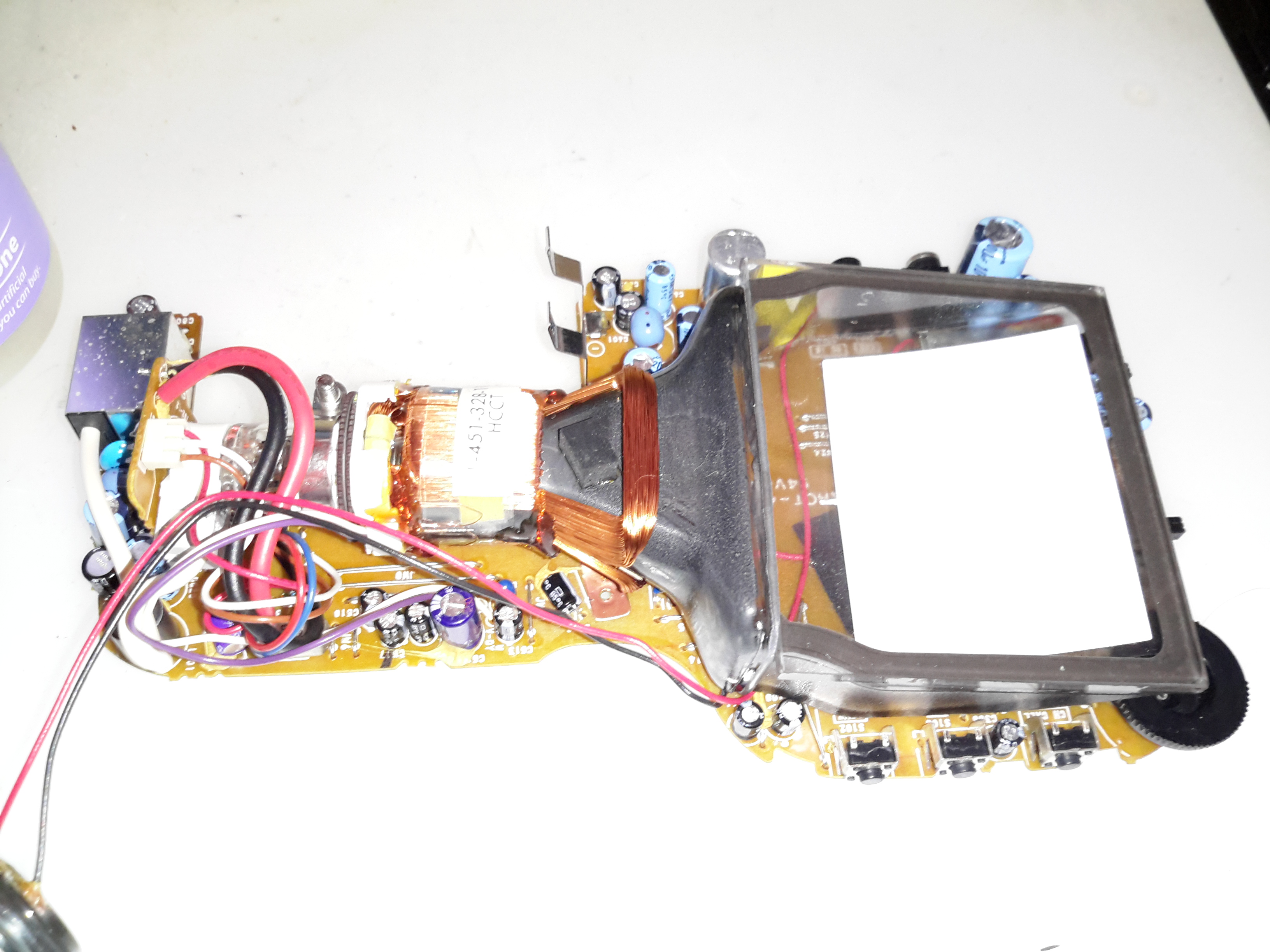
Electronics
Here’s the electronics completely removed from the shell. There’s much more integration in this model, everything is on a single PCB.
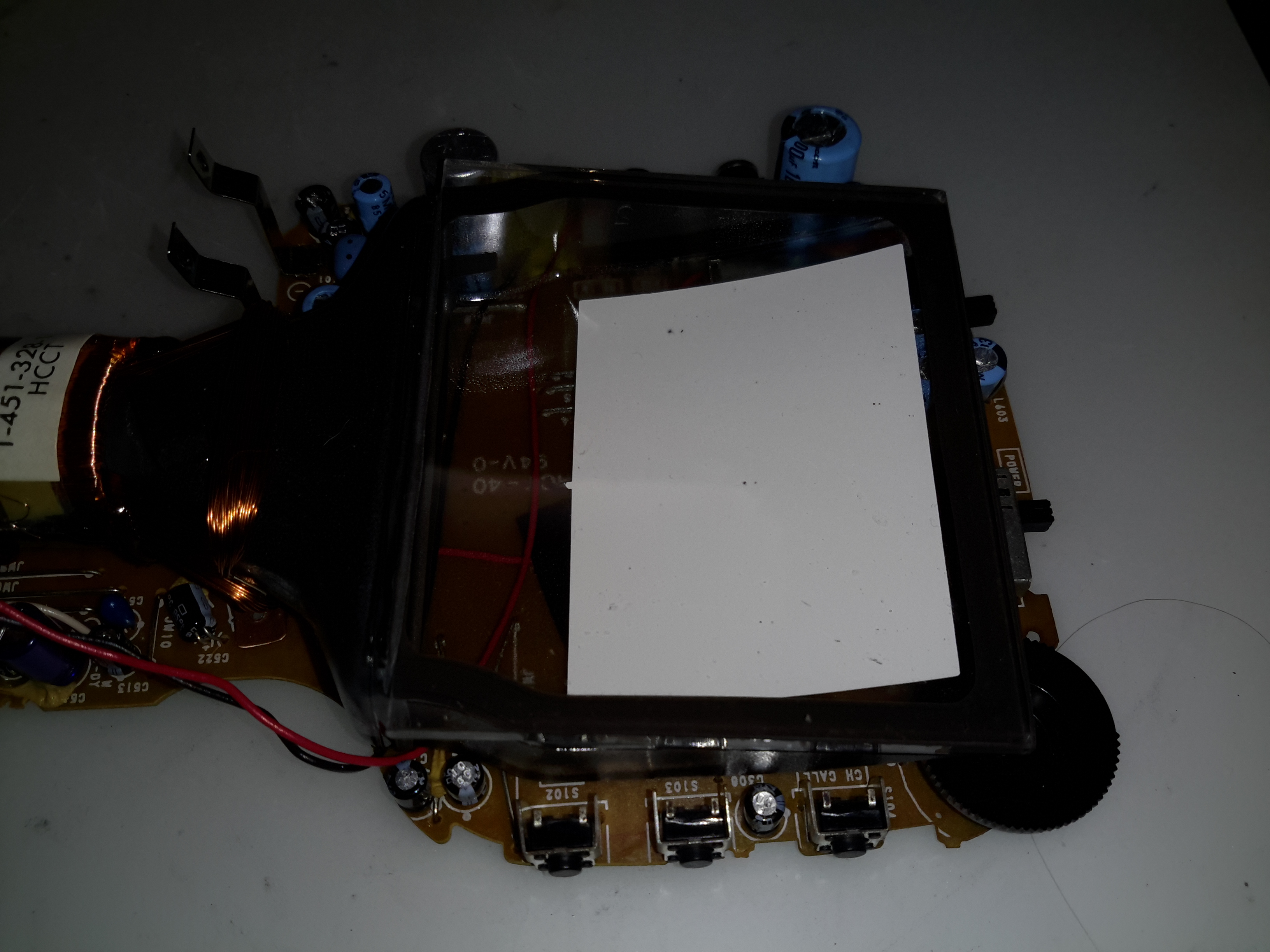
Phosphor Screen
The curve in the phosphor screen can clearly be seen here. This CRT seems to have been cost-reduced as well, with the rough edges on the glass components having been left unfinished.
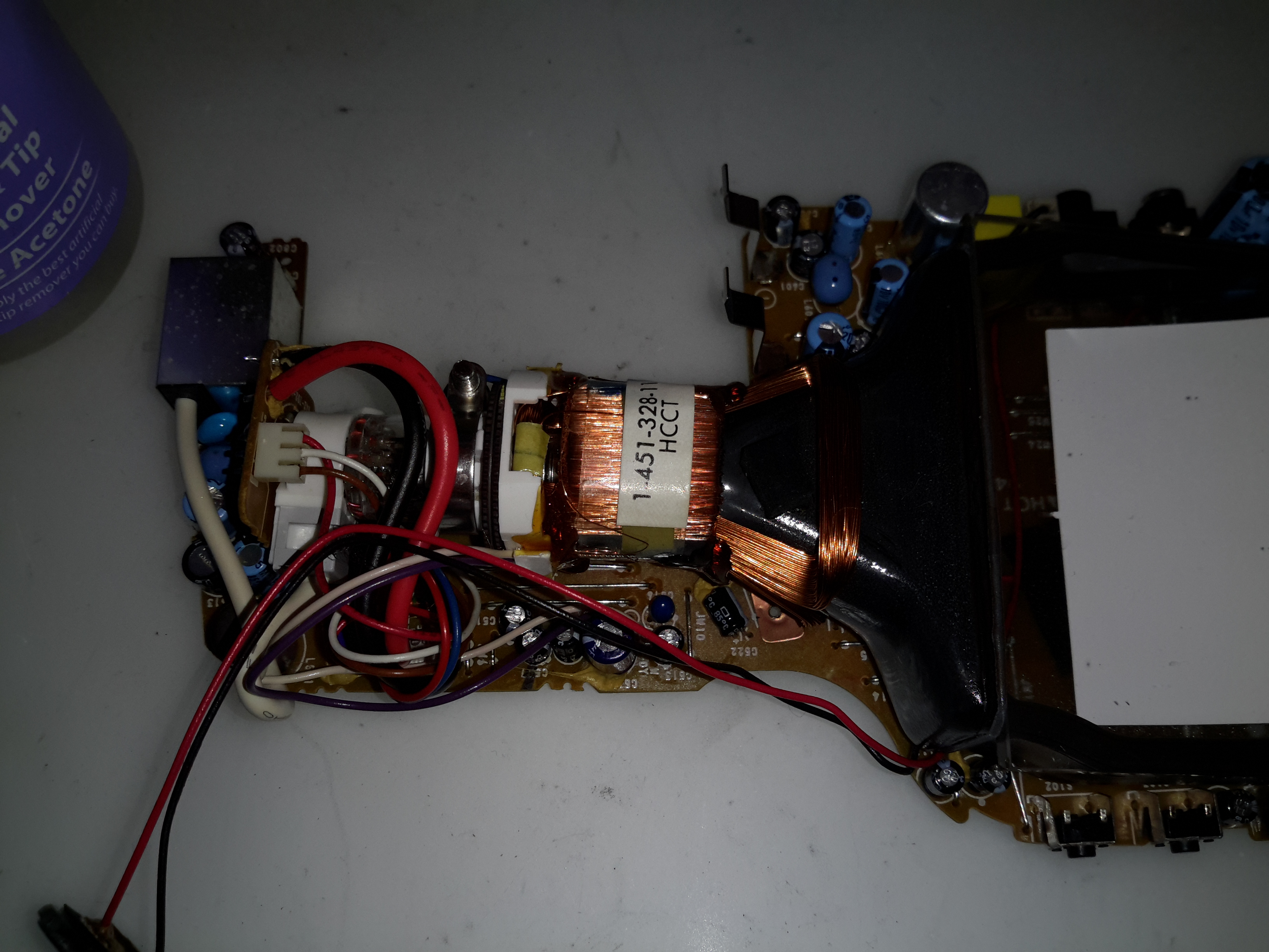
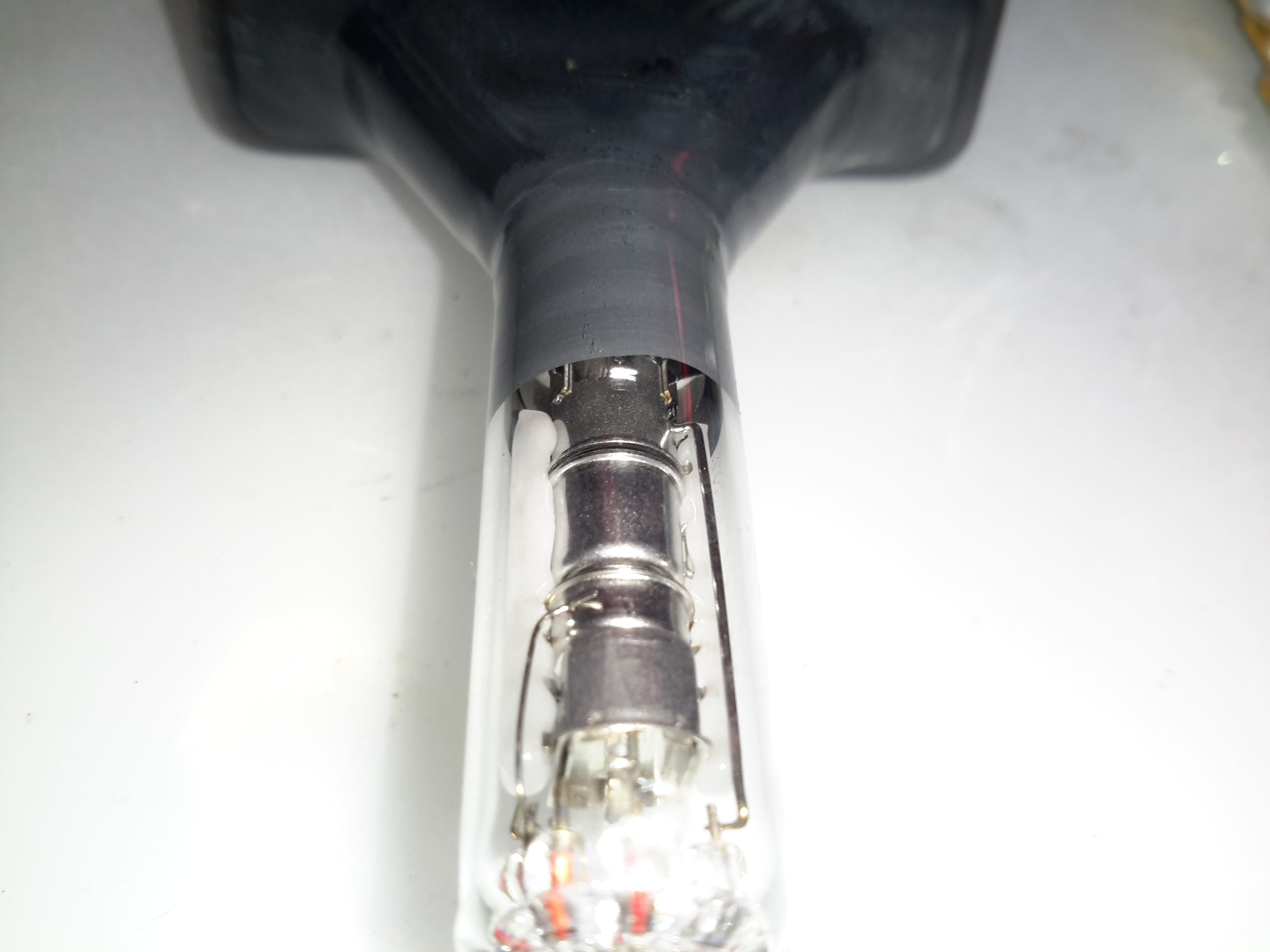
Electron Gun
Here’s the electron gun end of the tube. There isn’t a separate final anode connection to the bell of the tube unlike the previous model. Instead the final anode voltage is on a pin of the electron gun itself. This keeps all the wiring to the tube at one end & shortens the high voltage cable.
Electron Gun
Here’s the gun in the neck of the tube. Again this is pretty much standard fare for CRT guns. It’s more similar to a viewfinder tube in that the anode connection is running from the pins at the back. (It’s the line running up the right side of the tube). I’m guessing the anode voltage is pretty low for this to work without the HV flashing over, probably in the 2-4kV range.
Prior to the introduction of the CD player, the red He-Ne laser was by far the most common source of inexpensive coherent light on the planet. The following are some typical physical specifications for a variety of red (632.8 nm) He-Ne tubes (all are single transverse mode – TEM00):
   Output       Tube Voltage       Tube         Tube Size
   Power        Operate/Start     Current      Diam/Length
 ------------  ---------------  ------------  -------------
  0.3-0.5 mW    0.8-1.0/6  kV    3.0-4.0 mA     19/135 mm
  0.5-1 mW       .9-1.0/7  kV    3.2-4.5 mA     25/150 mm
   1-2 mW       1.0-1.4/8  kV    4.0-5.0 mA     30/200 mm
   2-3 mW       1.1-1.7/8  kV    4.0-6.5 mA     30/260 mm
   3-5 mW       1.7-2.4/10 kV    4.5-6.5 mA     37/350 mm
   5-10 mW      2.4-3.1/10 kV    6.5-7.0 mA     37/440 mm
  10-15 mW      3.0-3.5/10 kV    6.5-7.0 mA     37/460 mm
  15-25 mW      3.3-4.0/10 kV    6.5-7.0 mA     37/600 mm
  25-35 mW      4.0-5.2/12 kV    7.0-8.0 mA     42/900 mm
Where:
Power Output is the minimum beam power after a specified warm up period over the spec’d life of the tube.
Tube Operating Voltage is the voltage across the bare tube at the nominal operating current.
Tube Start Voltage is the minimum voltage across the bare tube required to guarantee starting.
Tube Size is generally the maximum diameter of the tube envelope and the total length from the outer surfaces of the mirrors.
Tubes like this are generally available in both random and linearly polarized versions which are otherwise similar with respect to the above characteristics (for red tubes at least, more below).
At least one other basic specification may be critical to your application: Which end of the tube the beam exits! There is no real preference from a manufacturing point of view for red He-Ne lasers. (For low gain “other-colour” He-Ne laser tubes, it turns out that anode output results is slightly higher gain and thus slightly higher output for the typical hemispherical cavity because it better utilizes the mode volume.) However, this little detail may matter a great deal if you are attempting to retrofit an existing barcode scanner or other piece of equipment where the tube clips into a holder or where wiring is short, tight, or must be in a fixed location. For example, virtually all cylindrical laser heads require that the beam exits from the cathode-end of the tube. It is possible that you will be able to find two versions of many models of He-Ne tubes if you go directly to the manufacturer and dig deep enough. However, this sort of information may not be stated where you are buying surplus or from a private individual, so you may need to ask.
The examples above (as well as all of the other specifications in this and the following sections) are catalog ratings, NOT what might appear on the CDRH safety sticker (which is typically much higher). See the section: About Laser Power Ratings for info on listed, measured, and CDRH power ratings.
Note how some of the power levels vary widely with respect to tube dimensions, voltage, and current. Generally, higher power implies a longer tube, higher operating/start voltages, and higher operating current – but there are some exceptions. In addition, you will find that physically similar tubes may actually have quite varied power output. This is particularly evident in the manufacturers’ listings. (See the chapter: A HREF=”laserhcl.htm#hcltoc”>Commercial Unstabilized HeNe Lasers.)
These specifications are generally for minimum power over the guaranteed life of the tube. New tubes and individual sample tubes after thousands of hours may be much higher – 1.5X is common and a “hot” sample may hit 2X or more. My guess is that for tubes with identical specifications in terms of physical size, voltage, and current, the differences in power output are due to sample-to-sample variations. Thus, like computer chips, they are selected after manufacture based on actual performance and the higher power tubes are priced accordingly! This isn’t surprising when considering the low efficiency at which these operate – extremely slight variations in mirror reflectivity and trace contaminants in the gas fill can have a dramatic impact on power output.
I have a batch of apparently identical 2 mW Aerotech tubes that vary in power output by a factor of over 1.5 to 1 (2.6 to 1.7 mW printed by hand on the tubes indicating measured power levels at the time of manufacture).
And, power output also changes with use (and mostly in the days of soft-sealed tubes, just with age sitting on the shelf):
(From: Steve Roberts.)
“I have a neat curve from an old Aerotech catalogue of He-Ne laser power versus life. The tubes are overfilled at first, so power is low. They then peak at a power much higher than rated power, followed by a long period of constant power, and then they SLOWLY die. It’s not uncommon for a new He-Ne tube to be in excess of 15% greater than rated power.”
And the answer to your burning question is: No, you cannot get a 3 mW tube to output 30 mW – even instantaneously – by driving it 10 times as hard!
I have measured the operating voltage and determined the optimum current (by maximizing beam intensity) for the following specific samples – all red (632.8 nm) tubes from various manufacturers. (The starting voltages were estimated.):
   Output     Tube Voltage       Tube         Supply Voltage     Tube Size
   Power      Operate/Start     Current        (75K ballast)    Diam/Length
 ----------  ---------------  ------------   ----------------  -------------
    .8 mW        .9/5  kV        3.2 mA           1.1 kV         19/135 mm
   1.0 mW       1.1/7  kV        3.5 mA           1.4 kV         25/150 mm
   1.0 mW       1.1/7  kV        3.2 mA           1.4 kV         25/240 mm
   2.0 mW       1.2/8  kV        4.0 mA           1.5 kV         30/185 mm
   3.0 mW       1.6/8  kV        4.5 mA           1.9 kV         30/235 mm
   5.0 mW       1.7/10 kV        6.0 mA           2.2 kV         37/350 mm
  12.0 mW       2.5/10 kV        6.0 mA           2.9 kV         37/475 mm
Melles Griot, Uniphase, Siemens, PMS, Aerotech, and other HeNe tubes all show similar values.
The wide variation in physical dimensions also means that when looking at descriptions of He-Ne lasers from surplus outfits or the like, the dimensions can only be used to determine an upper (and possibly lower) bound for the possible output power but not to determine the exact output power (even assuming the tube is in like-new condition). Advertisements often include the rating on the CDRH safety sticker (or say ‘max’ in fine print). This is an upper bound for the laser class (e.g., Class IIIa), not what the particular laser produces or is even capable of producing. It may be much lower. For example, that Class IIIa laser showing 5 mW on the sticker, may actually only be good for 1 mW under any conditions! The power output of a He-Ne laser tube is essentially constant and cannot be changed significantly by using a different power supply or by any other means. See the section: Buyer Beware for Laser Purchases.
In addition to power output, power requirements, and physical dimensions, key performance specifications for He-Ne lasers also include:
Beam Diameter at the laser’s output aperture and beam profile (Gaussian TEM00 for most small He-Ne laser tubes).
Beam Divergence (probably far field ignoring beam waist). Note that this may not always be the same as the expected value from the diffraction limit based on beam/bore diameter as it also depends on the combination of the HR and OC mirror (inside) curvature and the shape of the exterior surface of the OC.
Mode Spacing (frequency) between the multiple longitudinal modes that are active simultaneously in all but single mode frequency stabilized lasers.
With manufacturers like Aerotech, Melles Griot, and Siemens, a certain amount of information can be determined from the model number. For example, here is how to decipher most of those from Melles Griot (e.g., 05-LHP-121-278):
All Melles Griot He-Ne laser tubes and power supplies start with 05. Matched systems may start with 25 (e.g., laser head and lab-style power supply).
The first letter will be an L for all He-Ne laser tubes and heads except for perpendicular window terminated tubes (in which case it will be W – this is inconsistent with the rest of their numbering but who am I to complain!), and some of their self contained lasers where it will be S.
The second letter will be one of: H = red (632.8 nm), G = green (543.5 nm), Y = yellow (594.1 nm), O = orange (611.9 nm), or I = infra-red (1,523 or 3,391 nm). A couple of self contained red lasers use R for red but for most, I guess they got stuck using H (presumably denoting He-Ne) before ‘other colour’ He-Ne lasers were part of their product line. And, their stabilized He-Ne lasers use a T here. Confused yet? 🙂
The third letter will be one of: R = Randomly polarized, L = linearly polarized, or B = Brewster window at one or both ends.
The following three digit number determines the physical characteristics of the laser tube to some extent. Unfortunately, there may be no direct mathematical relationship of this number to anything useful. As will be seen below, for some models, it (or some of its digits) sort of correlates with output power or length but for others, they might as well be totally random! However, it does appear as though an identical set of numbers among different colour tubes (see below) will denote similar physical size tubes at least.
If there are additional numbers, they relate to a special variation on the basic design done for a particular customer. For example, this might be a different curvature on the outer surface of the output mirror to provide a non-standard divergence to eliminate the need for an additional lens in a barcode scanner. Or, an external window for protection from the elements or to deliberately reduce output power. Go figure. 🙂 It may also just denote a specific configuration like -249 (meaning 115 VAC operation, kind of arbitrary, huh?) or -55 (meaning 5.5 mA). In these cases, the user may be able to modify the settings (flip a switch or twiddle a pot) but the warranty may then be void.
The vast majority of Melles Griot lasers you are likely to come across will follow this numbering scheme though there are some exceptions, especially for custom assemblies. (Some surplus places drop the leading ’05-‘ when reselling Melles Griot laser tubes or heads so an 05-LHP-120 would become simply an LHP-120.)
For other manufacturers like Spectra-Physics, the model numbers are totally arbitrary!
He-Ne Tubes of a Different Colour
Although a red beam is what everyone thinks of when a He-Ne laser is discussed, He-Ne tubes producing green, yellow, and orange beams, as well as several infra-red (IR) wavelengths, are also manufactured. However, they are not found as often on the surplus market because they are not nearly as common as the red variety. In terms of the number of He-Ne lasers manufactured, red is far and away the most popular, with all the others combined accounting for only 1 to 2 percent of the total production. In order of decreasing popularity, it’s probably: red, green, yellow, infra-red (all IR wavelengths), orange. Non-red tubes are also more expensive when new since for a given power level, they must be larger (and thus have higher voltage and current ratings) due to their lower efficiency (the spectral lines being amplified are much weaker than the one at 632.8 nm). Operating current for non-red He-Ne tubes is also more critical than for the common red variety so setting these up with an adjustable power supply or adjusting the ballast resistance for maximum output is recommended.
Maximum available power output is also lower – rarely over 2 mW (and even those tubes are quite large (see the tables below). However, since the eye is more sensitive to the green wavelength (543.5 nm) compared to the red (632.8 nm) by more than a factor of 4, a lower power tube may be more than adequate for many applications. Yellow (594.1 nm) and orange (611.9 nm) He-Ne lasers appear more visible by factors of about 3 and 2 respectively compared to red beams of similar power.
Infrared-emitting He-Ne lasers exist as well. In addition to scientific uses, these were used for testing in the Telecom industry before sufficiently high quality diode lasers became available.Yes, you can have a He-Ne tube and it will light up inside (typical neon glow), but if there is no output beam (at least you cannot see one), you could have been sold an infrared He-Ne tube. However, by far the most likely explanation for no visible output beam is that the mirrors are misaligned or the tube is defective in some other way. Unfortunately, silicon photodiodes or the silicon sensors in CCD or CMOS cameras do not respond to any of the He-Ne IR wavelengths, so the only means of determining if there is an IR beam are to use a GaAs photodiode, IR detector card, or thermal laser power meter. IR He-Ne tubes are unusual enough that it is very unlikely you will ever run into one. However, they may turn up on the surplus market especially if the seller doesn’t test the tubes and thus realize that these behave differently – they are physically similar to red (or other colour) He-Ne tubes except for the reflectivity of the mirrors as a function of wavelength. (There may be some other differences needed to optimize each color like the He:Ne ratio, isotope purity, and gas fill pressure, but the design of the mirrors will be the most significant factor and the one that will be most obvious with a bare eyeball, though the color of the discharge may be more pink for green He-Ne tubes and more orange and brighter for IR He-Ne tubes compared to red ones, more below.) Even if the model number does not identify the tube as green, yellow, orange, red, or infra-red, this difference should be detectable by comparing the appearance of its mirrors (when viewed down the bore of an UNPOWERED tube) with those of a normal (known to be red) He-Ne tube. (Of course, your tube could also fail to lase due to misaligned or damaged mirrors or some other reason.
As noted above, the desired wavelength is selected and the unwanted wavelengths are suppressed mostly by controlling the reflectivity functions of the mirrors. For example, the gains of the green and yellow lines (yellow may be stronger) are both much much lower than red and separated from each other by about 50 nm (543.5 nm versus 594.1 nm). To kill the yellow line in a green laser, the mirrors are designed to reflect green but pass yellow. I have tested the mirrors salvaged from a Melles Griot 05-LGP-170 green He-Ne tube (not mine, from “Dr. Destroyer of Lasers”). The HR (High Reflector) mirror has very nearly 100% reflectivity for green but less than 25% for yellow. The OC (Output Coupler) also has a low enough reflectivity for yellow (about 98%) such that it alone would prevent yellow from lasing. The reflectivities for orange, red, and IR, are even lower so they are also suppressed despite their much higher gain, especially for the normal red (632.8 nm) and even stronger mid-IR (3,391 nm) line.
However, to manufacture a tube with optimum and stable output power, it isn’t sufficient to just kill lasing for unwanted lines. The resonator must be designed to minimize their contribution to stimulated emission – thus the very low reflectivity of the HR for anything but the desired green wavelength. Otherwise, even though sustained oscillation wouldn’t be possible, unwanted colour photons would still be bouncing back and forth multiple times stealing power from the desired colour. The output would also be erratic as the length of the tube changed during warm up (due to thermal expansion) and this affected the longitudinal mode structure of the competing lines relative to each other. Some larger He-Ne lasers have magnets along the length of the tube to further suppress (mostly) the particularly strong mid-IR line at 3,391 nm. (See the section: Magnets in High Power or Precision HeNe Laser Heads.)
In addition, you can’t just take a tube designed for a red laser, replace the mirrors, and expect to get something that will work well – if at all – for other wavelengths. For one thing, the bore size and mirror curvature for maximum power while maintaining TEM00 operation are affected by wavelength.
Furthermore, for these other colour He-Ne lasers which depend on energy level transitions which have much lower gain than red – especially the yellow and green ones – the gas fill pressure, He:Ne ratio, and isotopic composition and purity of the helium and neon, will be carefully optimized and will be different than for normal red tubes.
Needless to say, the recipes for each type and size laser will be closely guarded trade secrets and only a very few companies have mastered the art of other colour He-Ne lasers, especially for high power (in a relative sort of way) in yellow and green. I am only aware of four companies that currently manufacture their own tubes: Melles Griot, Research Electro-Optics, Uniphase, and LASOS, with the last two having very few models to choose from. Others (like Coherent) simply resell lasers under their own name.
And, the answer to that other burning question should now be obvious: No, you can’t convert an ordinary red internal mirror He-Ne tube to generate some other colour light as it’s (almost) all done with mirrors and they are an integral part of the tube. 🙂 Therefore, your options are severely limited. As in: There are none. (However, going the other way, at least as a fun experiment, may be possible. For a laser with external mirrors, a mirror swap may be possible (though the cavity length may be insufficient to resonate with the reduced gain of other-colour spectral lines once all loses taken into consideration). But realistically, this option doesn’t even exist where the mirrors are sealed into the tube.
There are also a few He-Ne lasers that can output more than one of the possible colors simultaneously (e.g., red+orange, orange+yellow) or selectively by turning knob (which adjusts the angle of a Littrow or other similar dispersion prism) inside the laser cavity using a Brewster window He-Ne tube). But such lasers are not common and are definitely very expensive. So, you won’t likely see one for sale at your local hamfest – if ever! One manufacturer of such lasers is Research Electro-Optics (REO). See the section: Research Electro-Optics’s Tunable HeNe Lasers.
However, occasionally a He-Ne tube turns up that is ‘defective’ due to incorrect mirror reflectivities or excessive gain or magic 🙂 and actually outputs an adjacent colour in addition to what it was designed to produce. I have such a tube that generates about 3 mW of yellow (594.1 nm) and a fraction of a mW of orange (611.9 nm) but isn’t very stable – power fluctuates greatly as it warms up. Another one even produces the other orange line at 611.9 nm, and it’s fairly stable. But, finding magic ‘defective’ tubes such as these by accident is extremely unlikely though I’ve heard of the 640.1 nm (deep red) line showing up on some supposedly good normal red (632.8 nm) He-Ne tubes.
As a side note: It is strange to see the more or less normal red-orange glow in a green He-Ne laser tube but have a green beam emerging. A diffraction grating or prism really shows all the lines that are in the glow discharge. Red through orange, yellow and green, even several blue lines (though they are from the helium and can’t lase under any circumstances)!! The IR lines are present as well – you just cannot see them.
Actually, the colour of the discharge may be subtly different for non-red He-Ne tubes due to modified gas fill and pressure. For example, the discharge of green He-Ne tubes may appear more pink compared to red tubes) which are more orange), mostly due to lower fill pressure. The fill mix and pressure on green He-Ne tubes is a tricky compromise among several objectives that conflict to some extent including lifetime, stability (3.39µm competition), and optical noise. This balancing act and the lower fill pressure are why green He-Ne tubes don’t last as long as reds. Have I totally confused you, colour-wise? 🙂
The expected life of ‘other colour’ He-Ne tubes is generally much shorter than for normal red tubes. This is something that isn’t widely advertised for obvious reasons. Whereas red He-Ne tubes are overfilled initially (which reduces power output) and they actually improve with use to some extent as gas pressure goes down, this luxury isn’t available with the low gain wavelengths – especially green – everything needs to be optimal for decent performance.
The discharge in IR He-Ne tubes may be more orange and brighter due to a higher fill pressure. Again, this is due to the need to optimize parameters for the specific wavelength.
Determining He-Ne Laser Colour from the Appearance of the Mirrors
Although most He-Ne lasers are the common red (632.8 nm) variety (whose beam actually appears orange-red), you may come across unmarked He-Ne tubes and just have to know what colour output the produce without being near a He-Ne laser power supply.
Since the mirrors used in all He-Ne lasers are dielectric – functioning as a result of interference – they have high reflectivity only around the laser wavelength and actually transmit light quite well as the wavelength moves away from this peak. By transmitted light, the appearance will tend to be a colour which is the complement of the laser’s output – e.g., cyan or blue-green for a red tube, pink or magenta for a green tube, blue or violet for a yellow tube. Of course, except for the IR variety, if the tube is functional, the difference will be immediately visible when it is powered up!
The actual appearance may also depend on the particular manufacturer and model as well as the length/power output of the laser (which affects the required reflectivity of the OC), as well as the revision number of your eyeballs. 🙂 So, there could be considerable variation in actual perceived colour. Except for the blue-green/magenta combination which pretty much guarantees a green output He-Ne tube, more subtle differences in colour may not indicate anything beyond manufacturing tolerances.
Appearance of He-Ne Laser Mirrors
The chart above in conjunction with will help to identify your unmarked He-Ne tube. (For accurate rendition of the graphic, your display should be set up for 24 bit colour and your monitor should be adjusted for proper colour balance.)
      HeNe Laser          High Reflector (HR)          Output Coupler (OC)
   Color  Wavelength   Reflection   Transmission    Reflection   Transmission
 ------------------------------------------------------------------------------
    Red    632.8 nm    Gold/Copper      Blue        Gold/Yellow   Blue/Green
   Orange  611.9 nm   Whitish-Gold      Blue       Metallic Green   Magenta
   Yellow  594.1 nm   Whitish-Gold      Blue       Metallic Green   Magenta
   Green   543.5 nm   Metallic Blue  Red/Orange    Metallic Green   Magenta

   Broadband (ROY)    Whitish-Gold      Blue

    IR     1,523 nm    Light Green  Light Magenta   Light Green  Light Magenta
    IR     3,391 nm       Gold (Metal) Coated         Neutral        Clear
The entry labelled ‘Broadband’ relates to the HR mirror in some unusual multiple colour (combinations of red and/or orange and/or yellow) internal mirror tubes as well as those with an internal HR and Brewster window for external OC optics. And, the yellow and orange tubes may actually use broad band HRs. The OCs would then be selected for the desired wavelength(s) and may also have a broad band coating.
For low gain tubes, they play games with the coatings. I guess it isn’t possible to just make a highly selective coating for one wavelength that’s narrow enough to have low reflectivity at the nearby lines so they won’t lase. So, one mirror will be designed to fall off rapidly on one side of the design wavelength, the other mirror on the other side. That’s one reason front and back mirrors on yellow and green tubes in particular have very different appearances.
As noted, depending on laser tube length/output power, manufacturer, and model, the appearance of the mirrors can actually vary quite a bit but this should be a starting point at least. For example, I have a Melles Griot 05-LHR-170 He-Ne laser tube that should be 594.1 nm (yellow) but actually outputs some 604.6 nm (orange) as well. It’s mirror colours for the HR and OC are almost exactly opposite of those I have shown for the yellow and orange tubes! I don’t know whether this was intentional or part of the problem And, while from this limited sample, it looks like the OCs for orange, yellow, and green He-Ne lasers appear similar, I doubt that they really are in the area that counts – reflectivity/transmission at the relevant wavelengths.
More on Other Colour He-Ne Lasers
Here are some comments on the difficulty of obtaining useful visible output from He-Ne lasers at wavelengths other than our friendly red (632.8 nm):
(From: Steve Roberts.)
You do need a isotope change in the gases for green, and a He:Ne ratio change for the other orange and yellow lines. In addition, the mirrors to go to another line will have a much lower output transmission. The only possible lines you’ll get on a large frame He-Ne laser will be the 611.9 nm orange and 594.1 nm yellow. The green requires external mirror tubes in excess of a meter and a half long and a Littrow prism to overcome the Brewster losses and suppress the IR.
The original work on green was done by Rigden and Wright. The short tubes have lower losses because they have no Brewsters and thus can concentrate on tuning the coatings to 99.9999% reflectivity and maximum IR transmission. There is one tunable low power unit on the market that does 6 lines or so, but only 1 line at a time, and the $6,000 cost is kind of prohibitive for a few milliwatts of red and fractional milliwatt powers on the other lines. But, it will do green and has the coatings on the back side of the prism to kill the losses.
Also look for papers by Erkins and Lee. They are the fellows who did the green and yellow for Melles Griot and they published one with the energy states as part of a poster session at some conference. Melles Griot used to hand it out, that’s how I had a copy, recently thrown away.
Even large He-Ne lasers such as the SP-125 (rated at 50mW of red) will only do about 20mW of yellow, with a 35mW SP-127 you’re probably only looking at 3 to 5mW of yellow. And, for much less then the cost of the custom optics to do a conversion, you can get two or three 4 to 5 mW yellow heads from Melles Griot. I know for a fact that a SP-127 only does about 3mW of 611.9 with a external prism and a remote cavity mirror, when it does 32mW of 632.8nm.
So in the end, unless you have a research use for a special line, it’s cheaper to dig up a head already made for the line you seek, unless you have your own optics coating lab that can fabricate state-of-the-art mirrors.
I have some experience in this, as I spent months looking for a source of the optics below $3,000.
(From: Sam.)
I do have a short (265 mm) one-Brewster He-Ne tube (Melles Griot 05-LGB-580) with its internal HR optimized for green that operates happily with a matching external green HR mirror (resulting in a nice amount of circulating power) but probably not with anything having much lower reflectivity to get a useful output beam. In fact, I could not get reliable operation even with the HR from a dead green He-Ne laser tube as the Brewster window would not remain clean enough for the time required to align the mirror.
I would expect an SP-127 to do more than 3 to 5 mW of yellow, my guess would be 10 to 15 mW with optimized mirrors but no tuning prism. If I can dig up appropriate mirrors, I intend to try modifying an SP-127 to make it tunable and/or do yellow or green. 🙂
You can find 640.1 nm in a lot of red He-Ne lasers. I have a paper on it somewhere, and cavity design can influence it to a large extent. If you have a decent quality grating, it’s pretty easy to pick up. 629 nm is the one you don’t see too much.
I’m no physicist, but the lower gain lines can lase simultaneously with the higher gain lines, no problem, as long as there is sufficient gain available in the plasma. It’s really pretty easy to get a He-Ne laser to output on all lines at the same time (if you have the right mirrors). The trick is optimizing the bore-to-mode ratio, gas pressure, and isotope mixture to get good TEM00 power. Usually the all-lines He-Ne lasers are multi (transverse) mode. I don’t know of anyone who makes them commercially though – at least not intentionally.
Steve’s Comments on Superradiance and the 3.39µm He-Ne Laser
Generally, when a gas laser is superradiant, there is a limit to its maximum power output (with exceptions for nitrogen and copper vapour laser, although nitrogen’s upper limit is defined by the maximum cavity length into which you can generate a 300ns or less excitation pulse.
The 3.39µm He-Ne laser’s gain is still, like all other He-Ne lines limited by a wall collision to return the excited atoms to the ground state. 3.39 µm He-Ne lasers have larger bores then normal He-Ne lasers, and the bores are acid etched to fog them and create more surface area, but still the most power I’ve ever seen published was 40 mW – nothing to write home about. The massive SP-125, the largest commercial He-Ne laser, could be ordered with a special tube and special optics for 3.39µm, and it still only did about 1/3rd the visible power. Superradiance and ultimate power are not tied together.
The reason 3.39µm got all the writeups it did was that it started on the same upper state as all the other He-Ne lines, was easily noticed when it sapped power from the visible line, and was, at the time, a exotic wavelength for which there were few other sources.
While I was already well aware of the effects of petrol on silicone products – the stuff swells up & dissolves over a very short period of time, which makes it an unsuitable material for seals in a petrol fuel system.
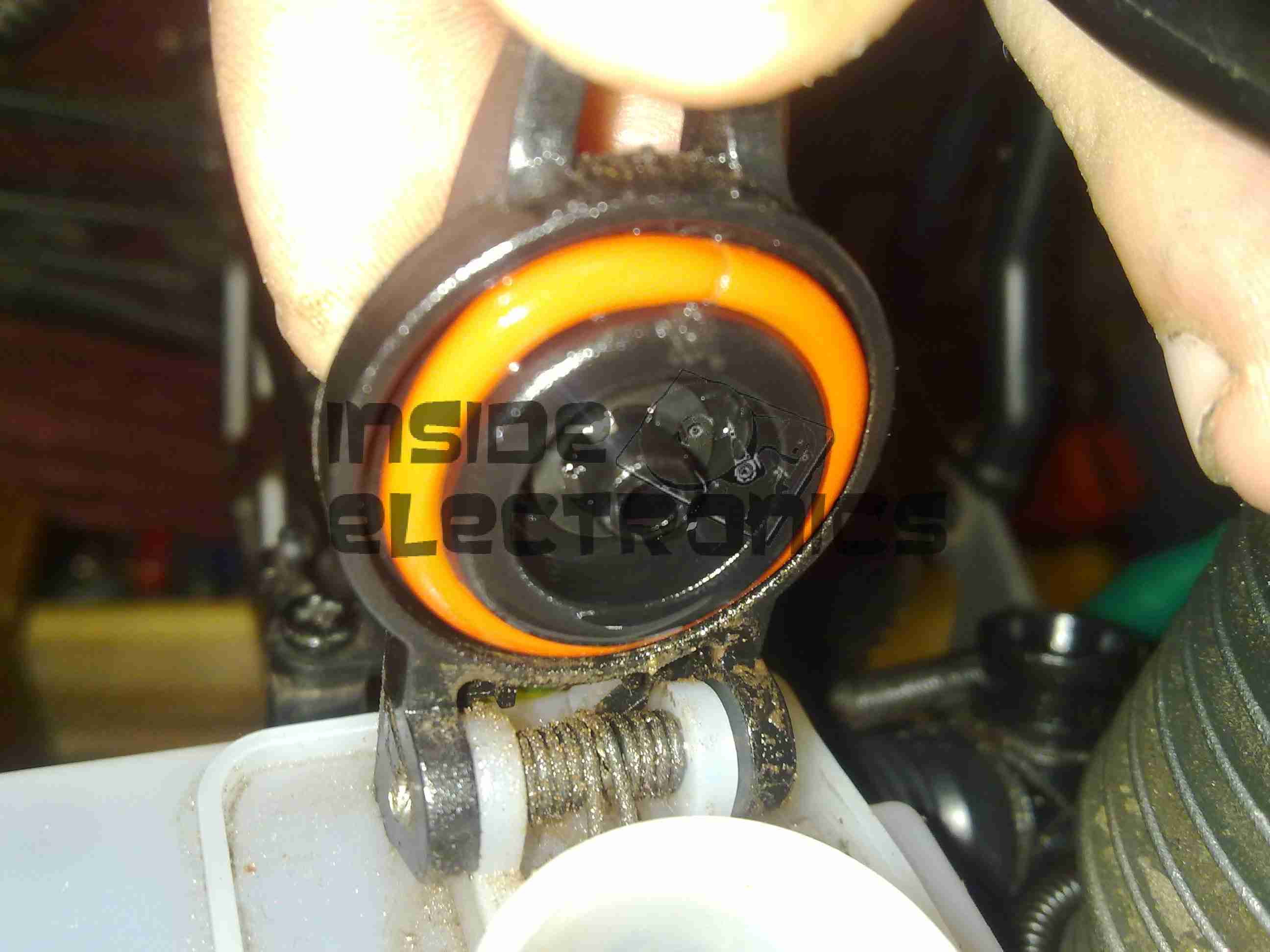
Fuel Tank Cap Seal
I wasn’t aware the O-Ring on the fuel tank cap of the Savage is silicone, as can be seen in the image above it has swelled up to much larger than it’s original size. It’s supposed to sit in the groove on the cap & fit into the filler neck when closed.
This was only from a couple of hours of petrol exposure, now the seal is such an ill fit that the cap will not close properly.
The solution here is to replace the ring with a Viton O-Ring, 2.5mm cross section, 23mm ID. I assume the fuel tank is made of polypropylene – this should stand up fine to the new fuel.
Another concern was the O-Rings on the carburettor needles, however these seem to be made of a petrol-resistant material already & are showing no signs of deterioration after 24+ hours of fuel immersion.
The O-Rings that seal the engine backplate to the crankcase also seem to be working fine with the new fuel.
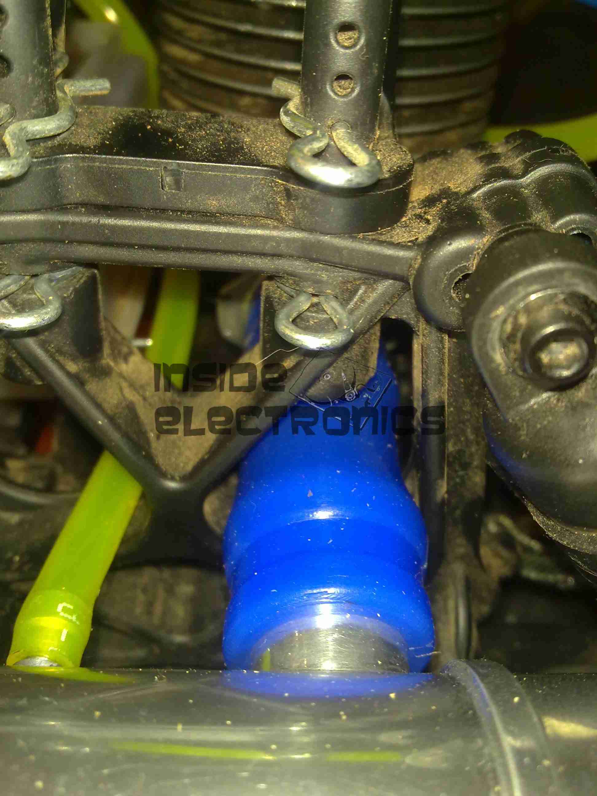
Another silicone part on the engine is the exhaust coupling, between the back of the cylinder & the silencer, I’m not aware of a suitable replacement as yet, although as it will mainly be exposed to the combustion products & not raw fuel, it may just survive the task.
Exhaust Coupling
The extra heat from burning petrol in one of these engines may also put a lot of stress on this component, if it eventually fails I may attempt a replacement with automotive hose – time will tell on this one.
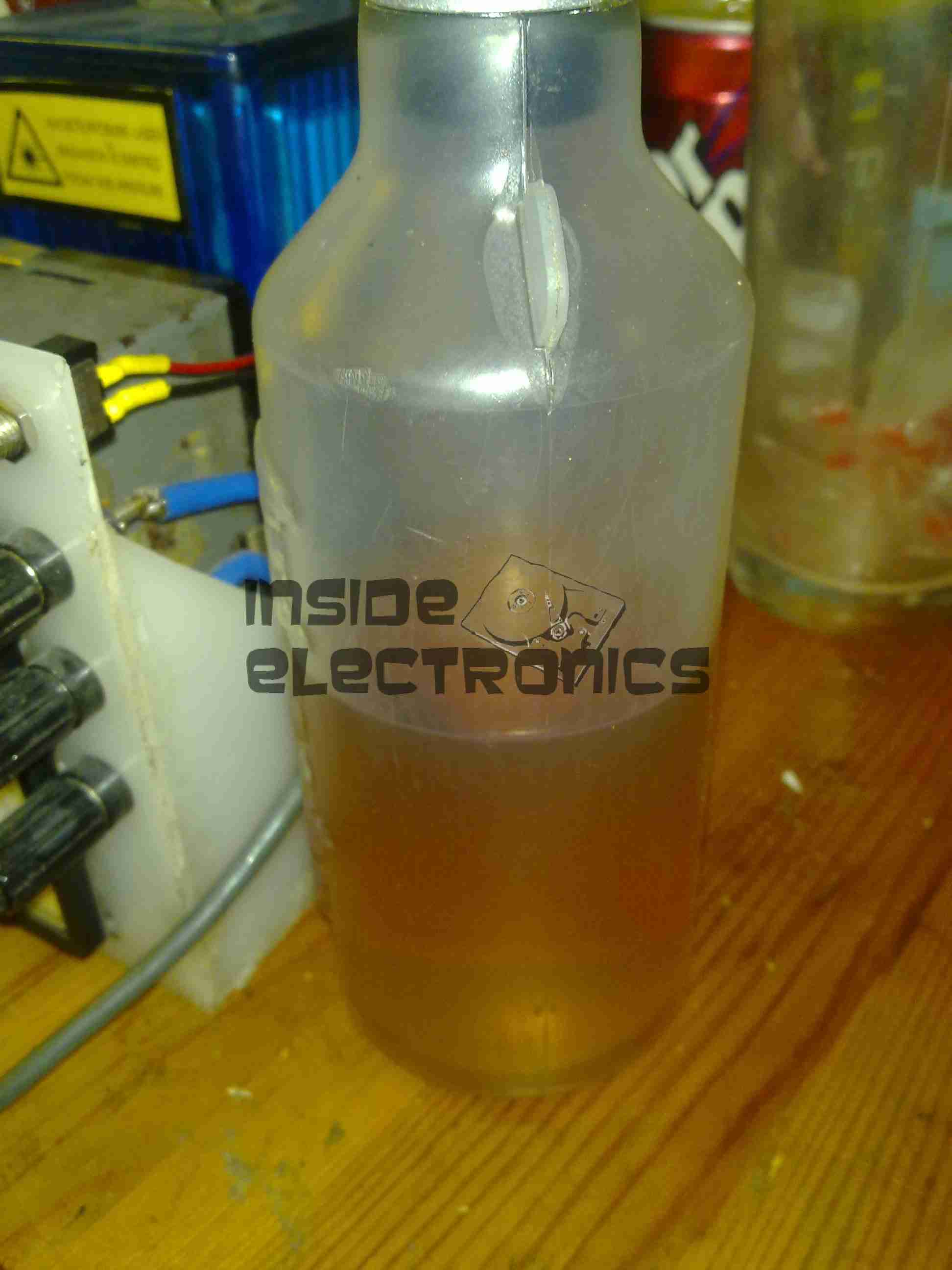
Fuel Bottle
I’m also not sure of the plastic that standard fuel bottles are made from – their resin identification number is 7, so it could be any special plastic, but I’m guessing it’s Nylon.
However according to the spec sheet for Nylon, it’s chemically compatible with petrol – yet the plastic appears to be getting softer with exposure, so it may be a special blend designed specifically for glow fuel.
Besides these small glitches, the engine is running well on it’s newly assigned diet of petrol, I’m currently running an 18:1 mix of petrol to oil (250ml oil to 4.5L of petrol), this seems to be providing more than adequate lubrication. While it smokes like a chimney, plenty of unburned oil is making it out of the exhaust, so the engine’s internals should have a liberal coating.
I’m yet to actually run the model out in open space so I can start tuning the mixture, but bench tests are promising.
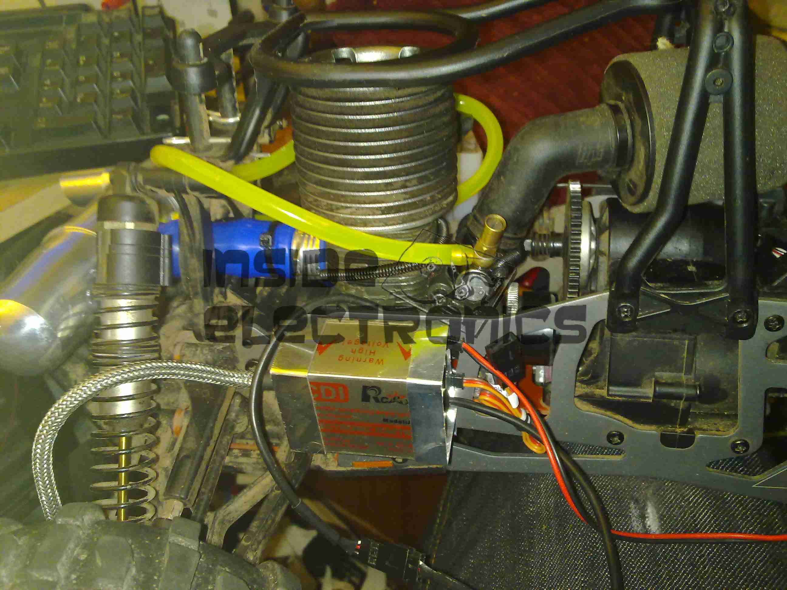
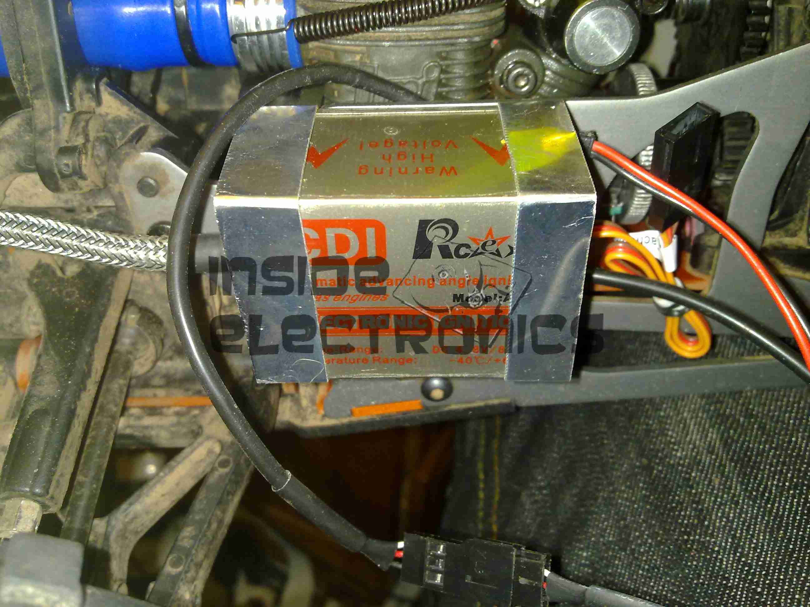
The engine now with it’s required ignition sensor, it is now mounted back on the chassis of the model. I have replaced the stock side exhaust with a rear silencer, so I could fit the ignition module in place next to the engine.
For the mounting, I fabricated a pair of brackets from 0.5mm aluminium, bent around the module & secured with the screws that attach the engine bed plate to the TVPs. The ignition HT lead can be routed up in front of the rear shock tower to clear all moving suspension parts, with the LT wiring tucked into the frame under the engine.
In this location the module is within the profile of the model chassis so it shouldn’t get hit by anything in service.
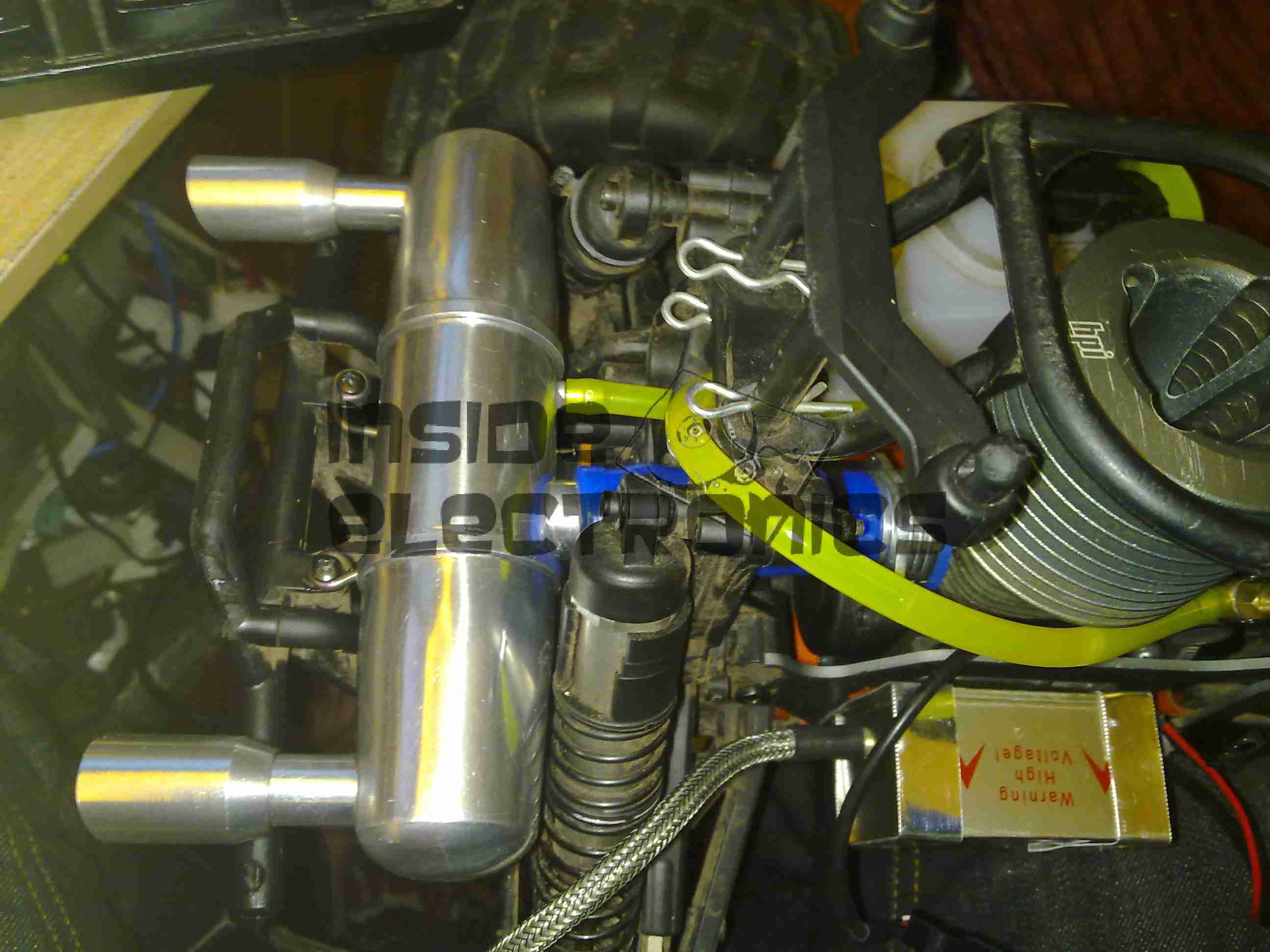
Rear Exhaust
New exhaust silencer fitted to the back of the model. This saves much space on the side of the model & allows the oily exhaust to be discharged away from the back wheel – no more mess to wipe up.
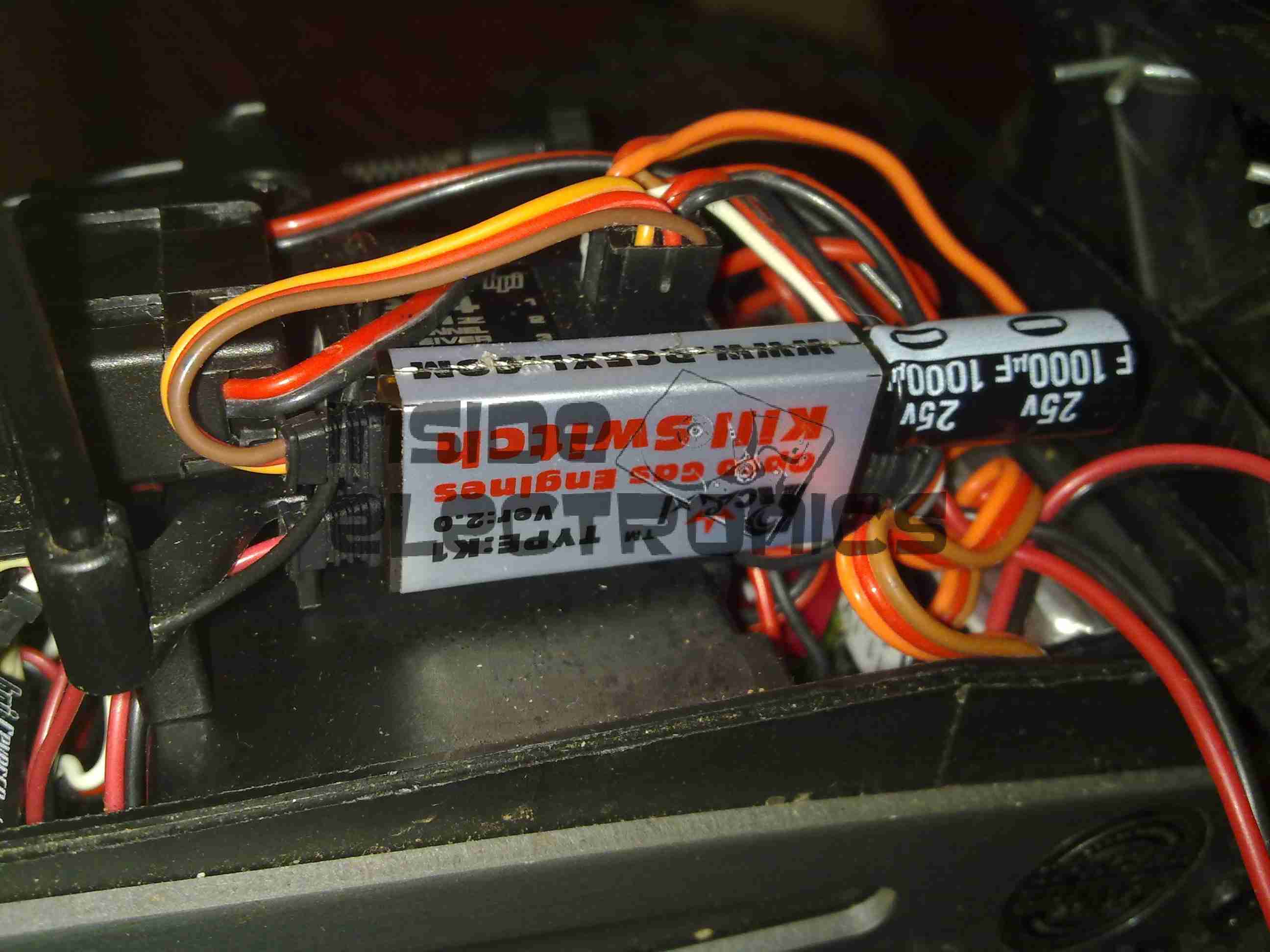
Kill Switch
The ignition switch fitted into the receiver box. This is wired into channel 3 of the TF-40 radio, allowing me to remotely kill the engine in case of emergency. I have fitted a 25v 1000µF capacitor to smooth out any power fluctuations from the ignition module.
The radio is running from a 11.1v 1Ah 3S LiPo pack connected to a voltage regulator to give a constant 6.5v for the electronics. I found this is much more reliable than the standard 5-cell Ni-MH hump packs.
Fuel Tank
The stock silicone fuel tubing has been replaced with Tygon tubing to withstand the conversion to petrol.
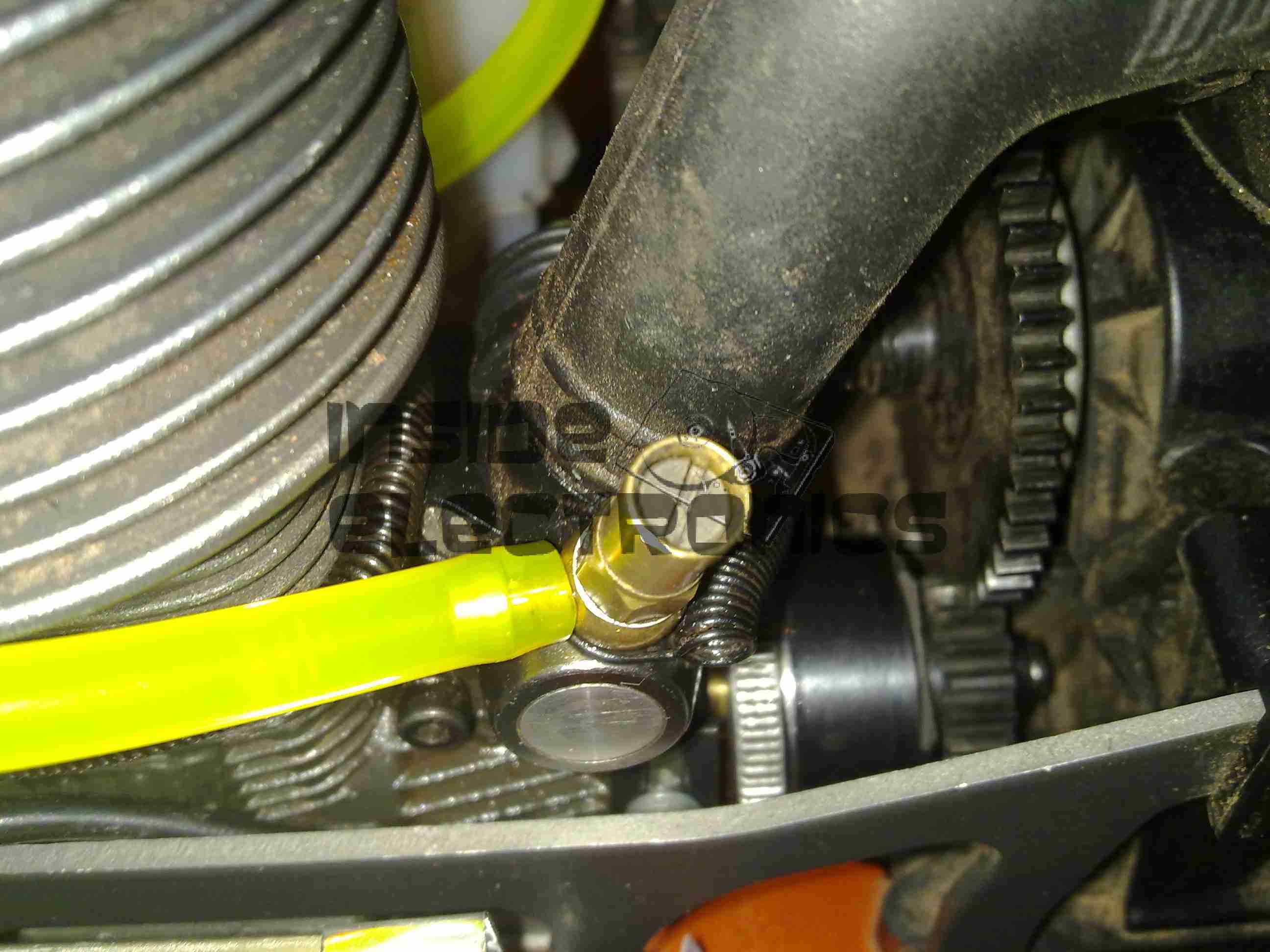
High Speed Needle
High speed needle tweaked to provide a basic running setting on petrol. This is set to ~1.5mm below flush with the needle housing.
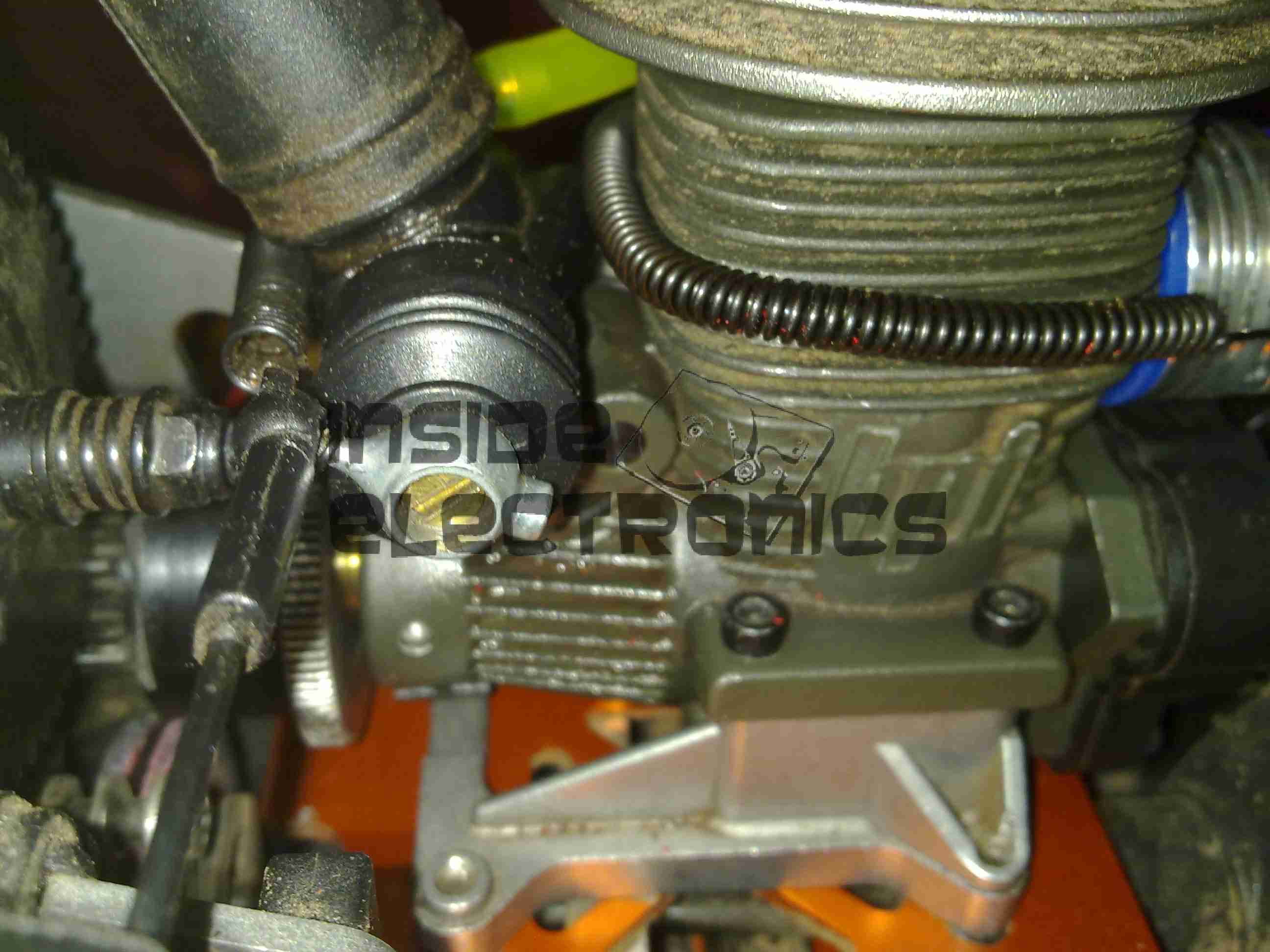
Low Speed Needle
Low speed needle tweaked to provide a basic running setting on petrol. This is set to ~1.73mm from flush with the needle housing.
As petrol is a much higher energy density fuel, it requires much more air than the methanol glow fuel – ergo much leaner settings.
The settings listed should allow an engine to run – if nowhere near perfectly as they are still rather rich. It’s a good starting point for eventual tuning.
Here are a few details of a valve amplifier I am building, using the valve related parts from a 1960’s reel to reel tape recorder.
This amplifier is based on an a Mullard ECL82 triode/pentode valve, with an EM84 magic eye tube for level indication.
Beginnings Of The Amplifier
Here the first components are being soldered to the tags on the valve holder, there are so few components that a PCB is not required, everything can be rats-nested onto the valve holders.
Progress
Progressing with the amplifier section componentry, all resistors are either 1/2W or 2W.
Valve Sockets Fitted
Here the valve holders have been fitted, along with the output transformer, DC smoothing capacitor & the filament wiring, into the top of the plastic housing. At this point all the components that complete the amplifier section are soldered to the bottom of the right hand valve holder.
Wiring
Starting the wiring between the valves & the power supply components. The volume control pot is fitted between the valve holders.
Valves Test Fit
The valves here are test fitted into their sockets, the aluminium can at the back is a triple 32uF 250v electrolytic capacitor for smoothing the B+ rail.
Amplifier Section First Test
First test of the amplifier, with the speaker from the 1960’s tape recorder from which the valves came from. the 200v DC B+ supply & the 6.3v AC filament supply is derived from the mains transformer in the background.
Magic Eye Tube Added
Here the magic eye tube has been fitted & is getting it’s initial tuning to the amplifier section. This requires selecting combinations of anode & grid resistors to set the gap between the bars while at no signal & picking a coupling RC network to give the desired response curve.
Final Test
Here both valves are fitted & the unit is sitting on it’s case for final audio testing. the cathodes of the ECL82 can be clearly seen glowing dull red here.
In the final section, I will build a SMPS power supply into the unit to allow it to be powered from a single 12v DC power supply.
This is an old cordless landline phone, with dead handset batteries.
Handset Radio Board
Here’s the handset with the back removed. Shown is the radio TX/RX board, underneath is the keyboard PCB with the speaker & mic. All the FM radio tuning coils are visible & a LT450GW electromechanical filter.
Handset Radio Board Bottom
Radio PCB removed from the housing showing the main CPU controlling the unit, a Motorola MC13109FB.
Keypad Board
The keypad PCB, with also holds the microphone & speaker.
Handset Keypad Board Bottom
Bottom of the keypad board, which holds a LSC526534DW 8-Bit µC & a AT93C46R serial EEPROM for phone number storage.
Base Main Board
Here’s the base unit with it’s top cover removed. Black square object on far right of image is the microphone for intercom use, power supply section is top left, phone interface bottom left, FM radio is centre. Battery snap for power backup is bottom right.
Power Supply Section
PSU section of the board on the left here, 9v AC input socket at the bottom, with bridge rectifier diodes & main filter capacitor above. Two green transformers on the right are for audio impedance matching. Another LT450GW filter is visible at the top, part of the base unit FM transceiver.
ICs
Another 8-bit µC, this time a LSC526535P, paired with another AT93C46 EEPROM. Blue blob is 3.58MHz crystal resonator for the MCU clock. The SEC IC is a KS58015 4-bit binary to DTMF dialer IC. This is controlled by the µC.
Base Main Board Bottom
Underside of the base unit Main PCB, showing the matching MC13109FB IC for the radio functions.
Tip Jar
If you’ve found my content useful, please consider leaving a donation by clicking the Tip Jar below!
All collected funds go towards new content & the costs of keeping the server online.