Posted on Leave a comment

HPI Savage X 4.6 Ignition Conversion – Initial Carburettor Settings & Module Mountings

Ignition Module Mount
Ignition Module
Ignition Module

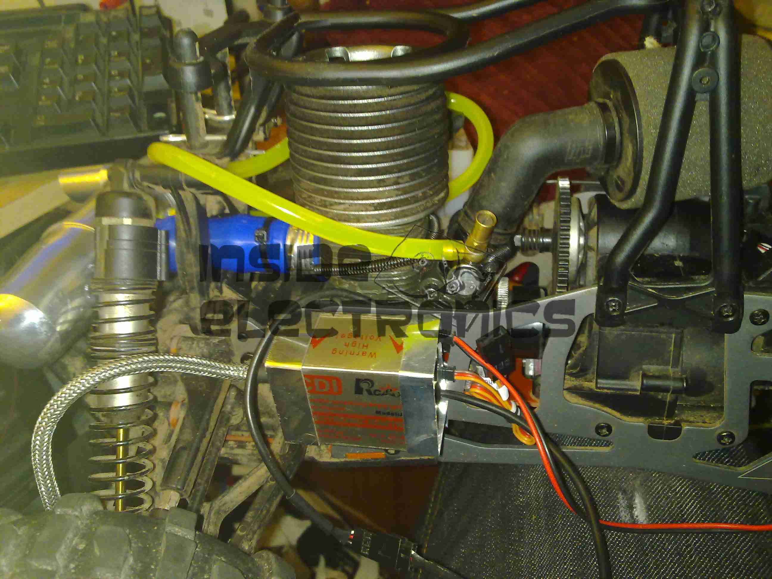
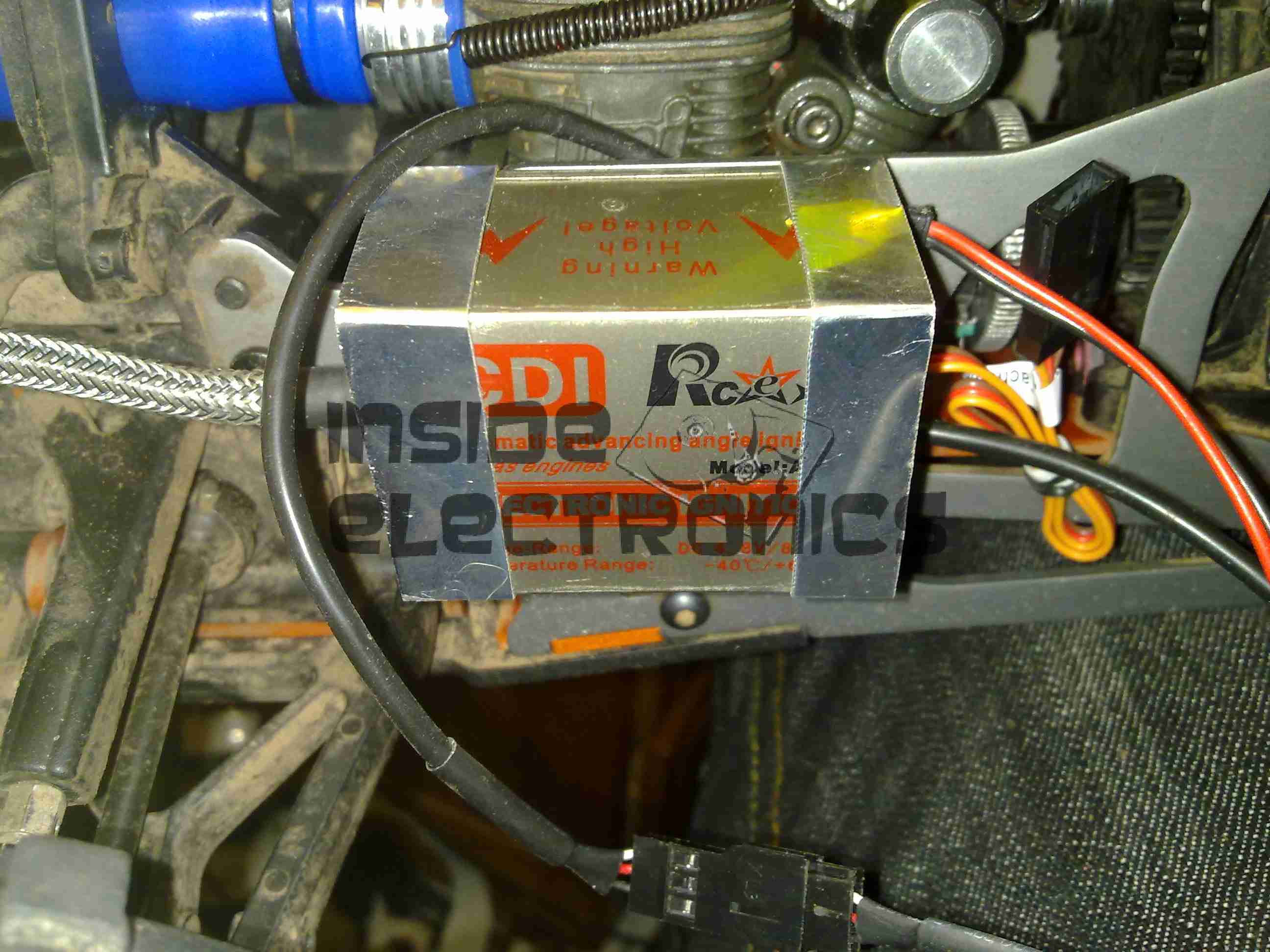
The engine now with it’s required ignition sensor, it is now mounted back on the chassis of the model. I have replaced the stock side exhaust with a rear silencer, so I could fit the ignition module in place next to the engine.
For the mounting, I fabricated a pair of brackets from 0.5mm aluminium, bent around the module & secured with the screws that attach the engine bed plate to the TVPs. The ignition HT lead can be routed up in front of the rear shock tower to clear all moving suspension parts, with the LT wiring tucked into the frame under the engine.
In this location the module is within the profile of the model chassis so it shouldn’t get hit by anything in service.

Rear Exhaust
Rear Exhaust

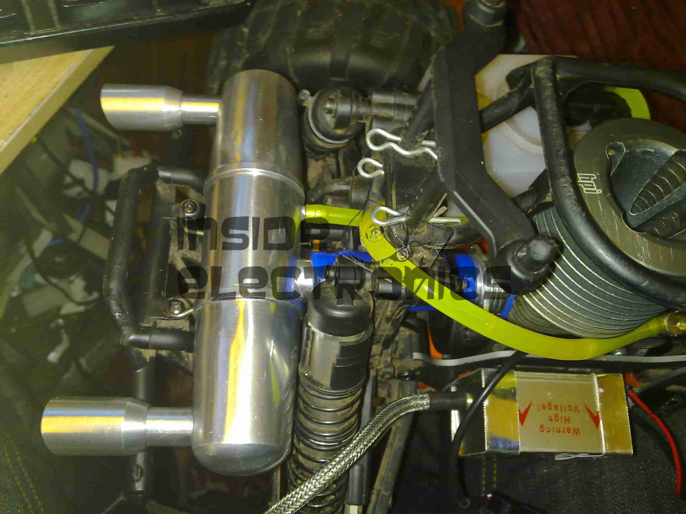
New exhaust silencer fitted to the back of the model. This saves much space on the side of the model & allows the oily exhaust to be discharged away from the back wheel – no more mess to wipe up.

Kill Switch
Kill Switch

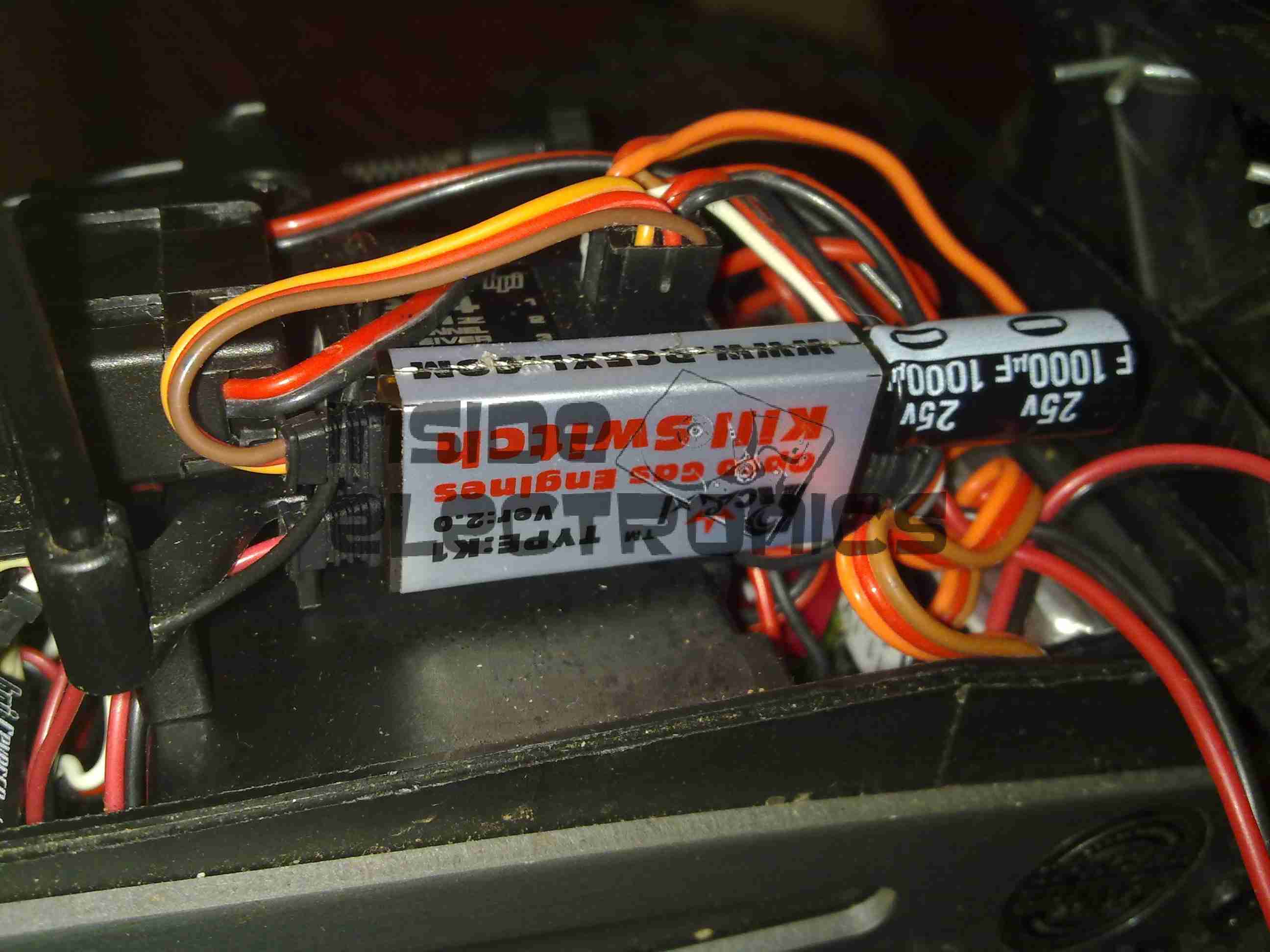
The ignition switch fitted into the receiver box. This is wired into channel 3 of the TF-40 radio, allowing me to remotely kill the engine in case of emergency. I have fitted a 25v 1000µF capacitor to smooth out any power fluctuations from the ignition module.
The radio is running from a 11.1v 1Ah 3S LiPo pack connected to a voltage regulator to give a constant 6.5v for the electronics. I found this is much more reliable than the standard 5-cell Ni-MH hump packs.

Fuel Tank
Fuel Tank

The stock silicone fuel tubing has been replaced with Tygon tubing to withstand the conversion to petrol.

High Speed Needle
High Speed Needle

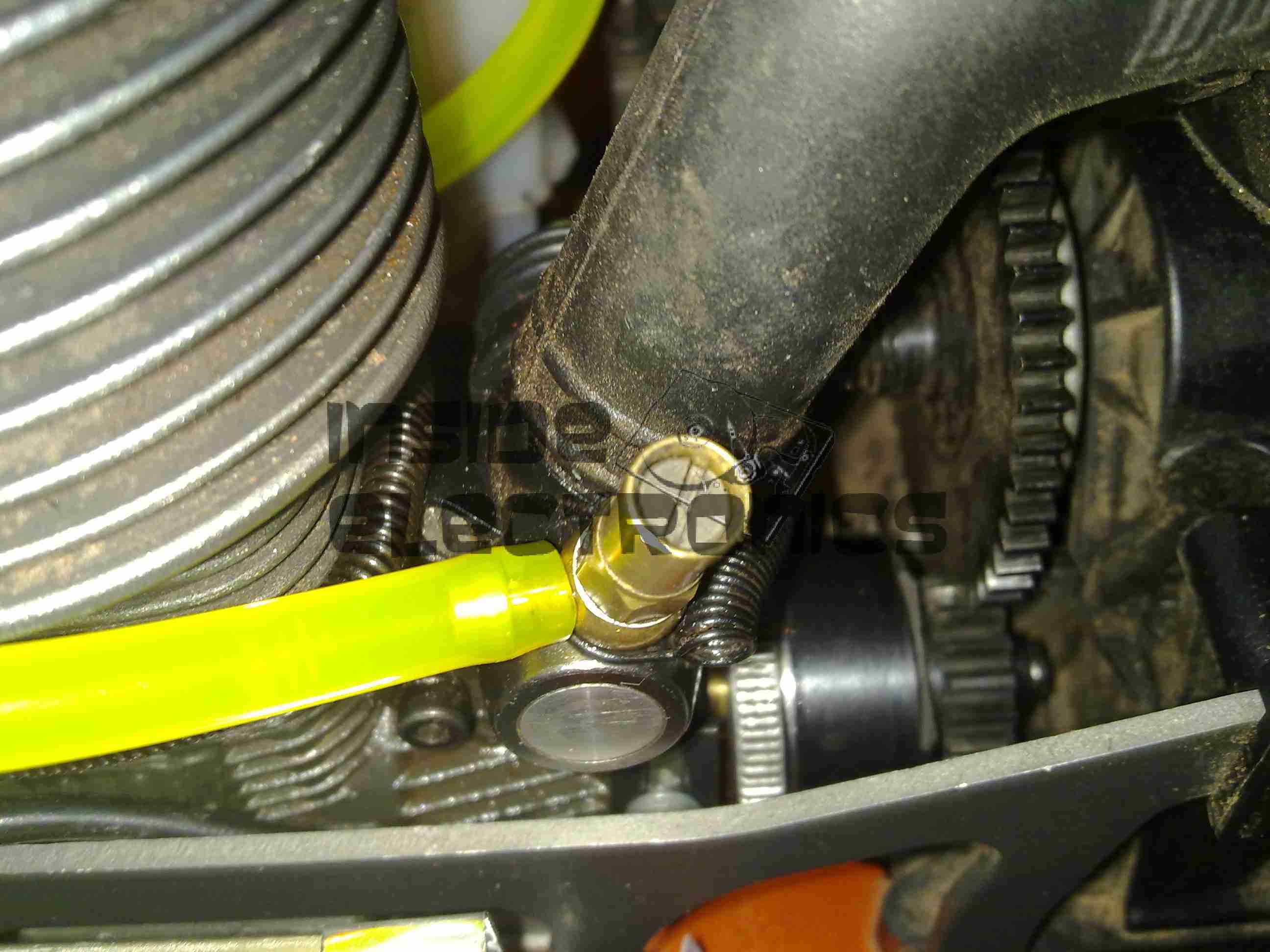
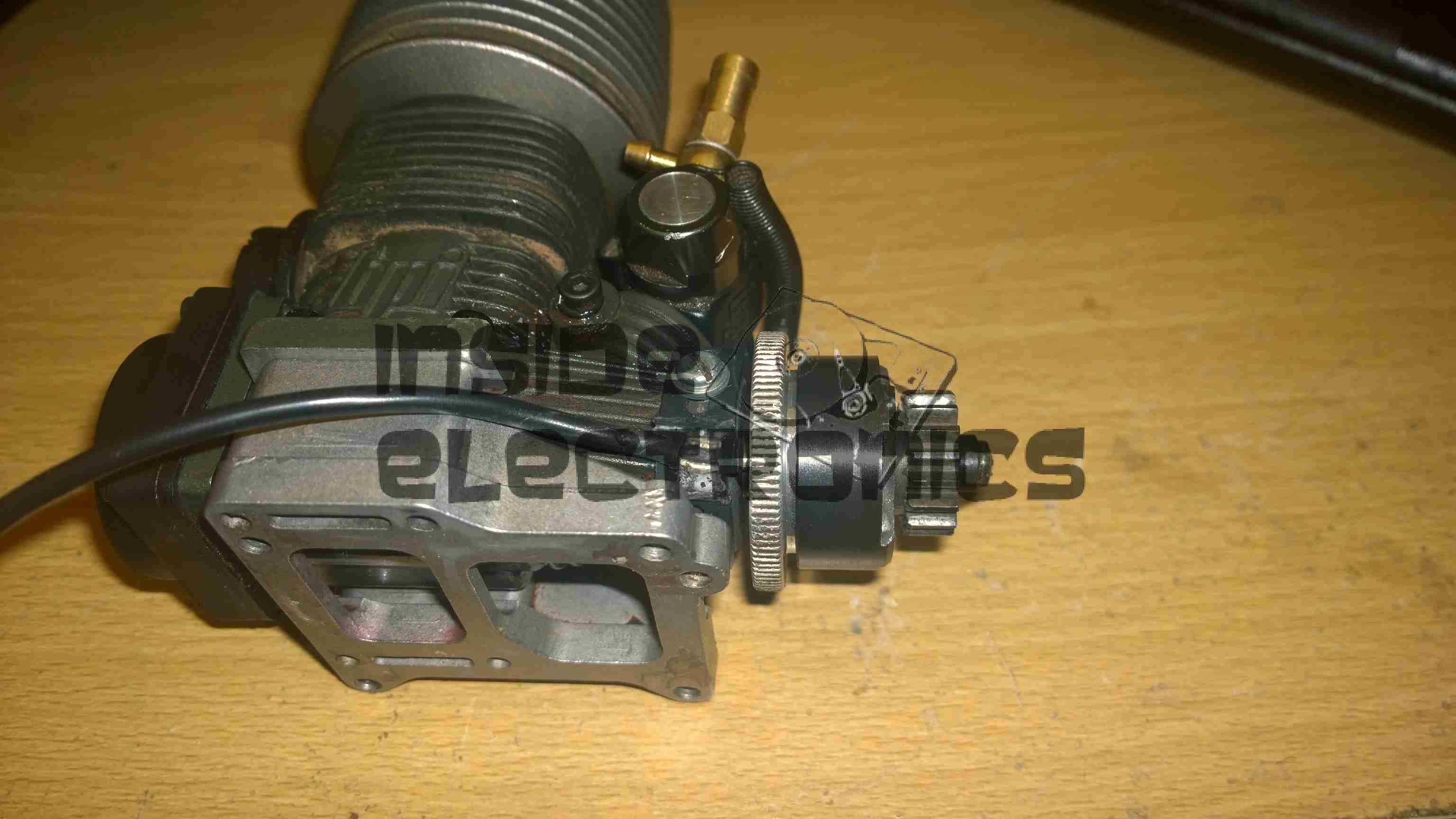
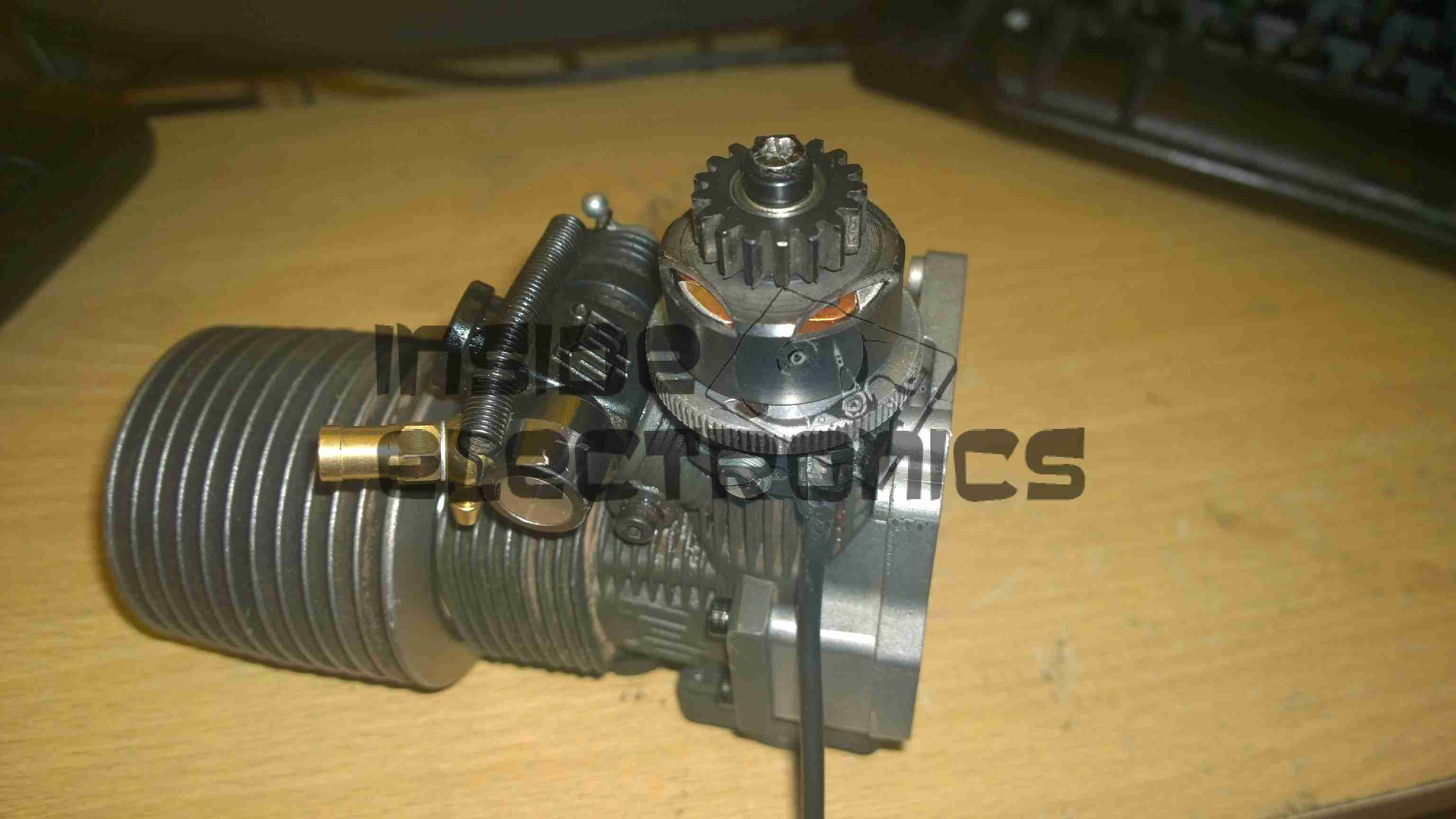
High speed needle tweaked to provide a basic running setting on petrol. This is set to ~1.5mm below flush with the needle housing.

Low Speed Needle
Low Speed Needle

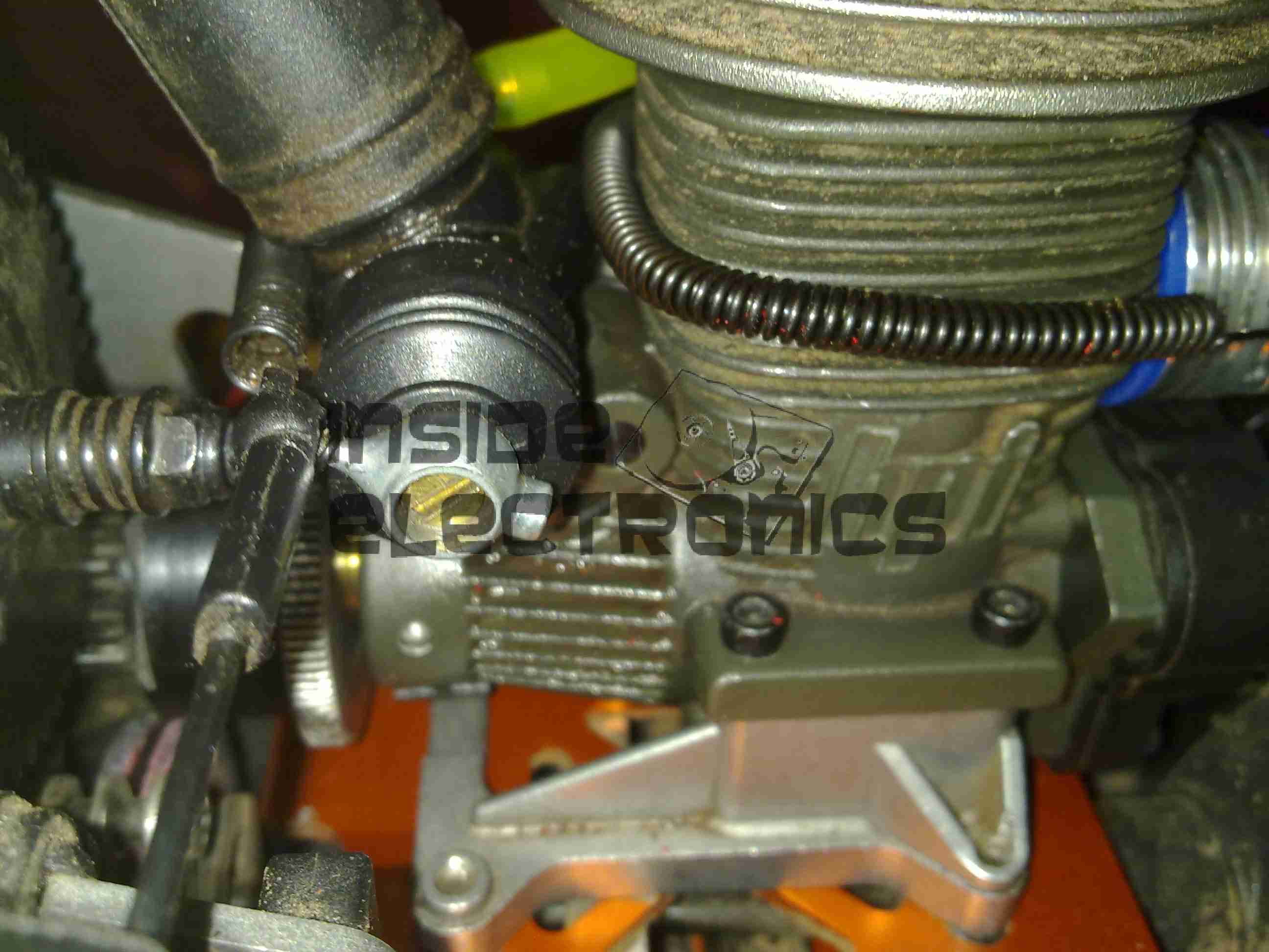
Low speed needle tweaked to provide a basic running setting on petrol. This is set to ~1.73mm from flush with the needle housing.

As petrol is a much higher energy density fuel, it requires much more air than the methanol glow fuel – ergo much leaner settings.
The settings listed should allow an engine to run – if nowhere near perfectly as they are still rather rich. It’s a good starting point for eventual tuning.


Posted on Leave a comment

HPI Nitrostar F4.6 Ignition Conversion

As there was no other online example of someone converting a glow/nitro car engine onto CDI ignition, I thought I would document the highlights here.
The engine is currently still running on glow fuel, but when the required fuel lines arrive I will be attempting the switch over to 2-Stroke petrol mix. This should definitely save on fuel costs.

The engine in this case is a HPI NitroStar F4.6 nitro engine, from a HPI Savage X monster truck.

F4.6 Engine
F4.6 Engine

Above is the converted engine with it’s timing sensor. As The installation of this was pretty much standard, a complete strip down of the engine was required to allow the drilling & tapping of the two M3x0.5 holes to mount the sensor bracket to. The front crankshaft bearing has to be drifted out of the crankcase for this to be possible.

Ignition Hall Sensor

Detail of the ignition hall sensor. The bracket has to be modified to allow the sensor to face the magnet in the flywheel. Unlike on an Aero engine, where the magnet would be on the outside edge of the prop driver hub, in this case the hole was drilled in the face of the flywheel near the edge & the magnet pressed in. The Hall sensor is glued to the modified bracket with the leads bent to position the smaller face towards the back of the flywheel.
The clearance from the magnet to sensor is approx. 4mm.

Flywheel Magnet
Flywheel Magnet

Detail of the magnet pressed into the flywheel. A 3.9mm hole was drilled from the back face, approx 2mm from the edge, & the magnet pressed into place with gentle taps from a mallet & drift, as I had no vice to hand.
Initial timing was a little fiddly due to the flywheel only being held on with a nut & tapered sleeve, so a timing mark can be made inside the rear of the crankcase, across the crank throw & case to mark the 28 degree BTDC point, the flywheel is then adjusted to make the ignition fire at this point, before carefully tightening the flywheel retaining nut to ensure no relative movement occurs.
The slots in the sensor bracket allow several degrees of movement to fine adjust the timing point once this rough location has been achieved.

1/4"-32 Spark Plug
1/4″-32 Spark Plug

Definitely the tiniest spark plug I’ve ever seen, about an inch long. Some trouble may be encountered with this on some engines – the electrodes stick out about 2mm further into the combustion chamber than a standard glow plug does. This causes the ground electrode to hit the top of the piston crown. (This happens on the HPI NitroStar 3.5 engine). The addition of another copper washer under the plug before tightening should cure this problem.

RcExl CDI Ignition Module

Ignition module. Due to the depth of the plug in the heatsink head on these engines, I will have to modify the plug cap to straighten it out, as it will not fit in this configuration.
However, ignition modules are available from HobbyKing with straight plug caps, this makes modification unnecessary

The ignition & components used on this system were obtained from JustEngines.