Posted on Leave a comment

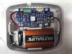
Wireless Energy Management SmartSensor

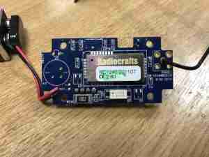
Cover Removed
Cover Removed

Here’s another random bit of RF tech, I’m told this is a wireless energy management sensor, however I wasn’t able to find anything similar on the interwebs. It’s powered by a standard 9v PP3 battery.

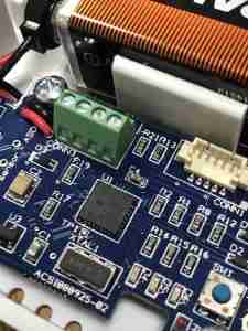
Microcontroller
Microcontroller

System control is handled by this Microchip PIC18F2520 Enhanced Flash microcontroller, this has an onboard 10-bit ADC & nanoWatt technology according to their datasheet. There’s a 4MHz crystal providing the clock, with a small SOT-23 voltage regulator in the bottom corner. There’s a screw terminal header & a plug header, but I’ve no idea what these would be used for. Maybe connecting an external voltage/current sensor & a programming header? The tactile button I imagine is for pairing the unit with it’s controller.

PCB Bottom
PCB Bottom

The bottom of the PCB is almost entirely taken up by a Radiocrafts RC1240 433MHz RF transceiver. Underneath there’s a large 10kΩ resistor, maybe a current transformer load resistor, and a TCLT1600 optocoupler. Just from the opto it’s clear this unit is intended to interface in some way to the mains grid. The antenna is connected at top right, in a footprint for a SMA connector, but this isn’t fitted.

Posted on 4 Comments

DIY Eberspacher Glowplug Screens: The Test Of Time

Some time ago I did a couple of posts on cheapening up the maintenance of Eberspacher hot air heaters by making the glow plug screens myself. Now one of my pieces of stainless mesh has been in the heater for nearly a year, and the heater is starting to get a bit smoky on a cold start. This is usually a sign that the screen isn’t allowing the fuel to vaporise quick enough for the glow plug to ignite the flame, because it’s becoming blocked. So far the heater has had about 150L of diesel through it with my DIY screen.

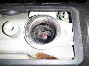
Old Screen
Old Screen

After removing the plug, here’s what’s left of the screen. The bottom end has completely disintegrated, but this is to be expected – OEM screens do the same thing as this end is exposed to the most heat in the burner. There’s quite a bit of coke buildup on the top end of the screen around the fuel nozzle, again this isn’t surprising, as this is the coolest part of the heater not all the heavier fractions of the diesel fuel have the chance to vaporise.

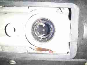
Innards
Innards

Looking further down into the mixing tube of the main burner, everything looks good. There’s a coating of soot in there, but no tar-like build up that would tell me the unit isn’t burning properly. Another advantage of making my own screens is that they’re much easier to extract from the hole once they’ve been in there for months. The OEM screens have a stainless ring spot welded to the mesh itself to hold it’s shape, and once there’s enough fuel residue built up the entire mess seizes in place, requiring some sharp pokey tools & some colourful language to remove. The single loop of mesh held in place by it’s own spring pressure is much easier to remove as it collapses easily.

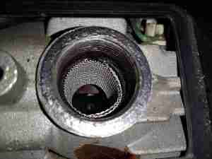
New 80 Mesh Screen
New 80 Mesh Screen

I’ve decided to change the mesh size of the screen while I’m in here, in this case to 80 mesh, which is much closer to the OEM screen size. There doesn’t seem to be much of a difference so far in either the starting or running capability of the heater, although the thicker wire of this screen might last longer before disintegrating at the burner end.

Posted on Leave a comment

Inductive Hour Counter / Tachometer – Petrol Engines

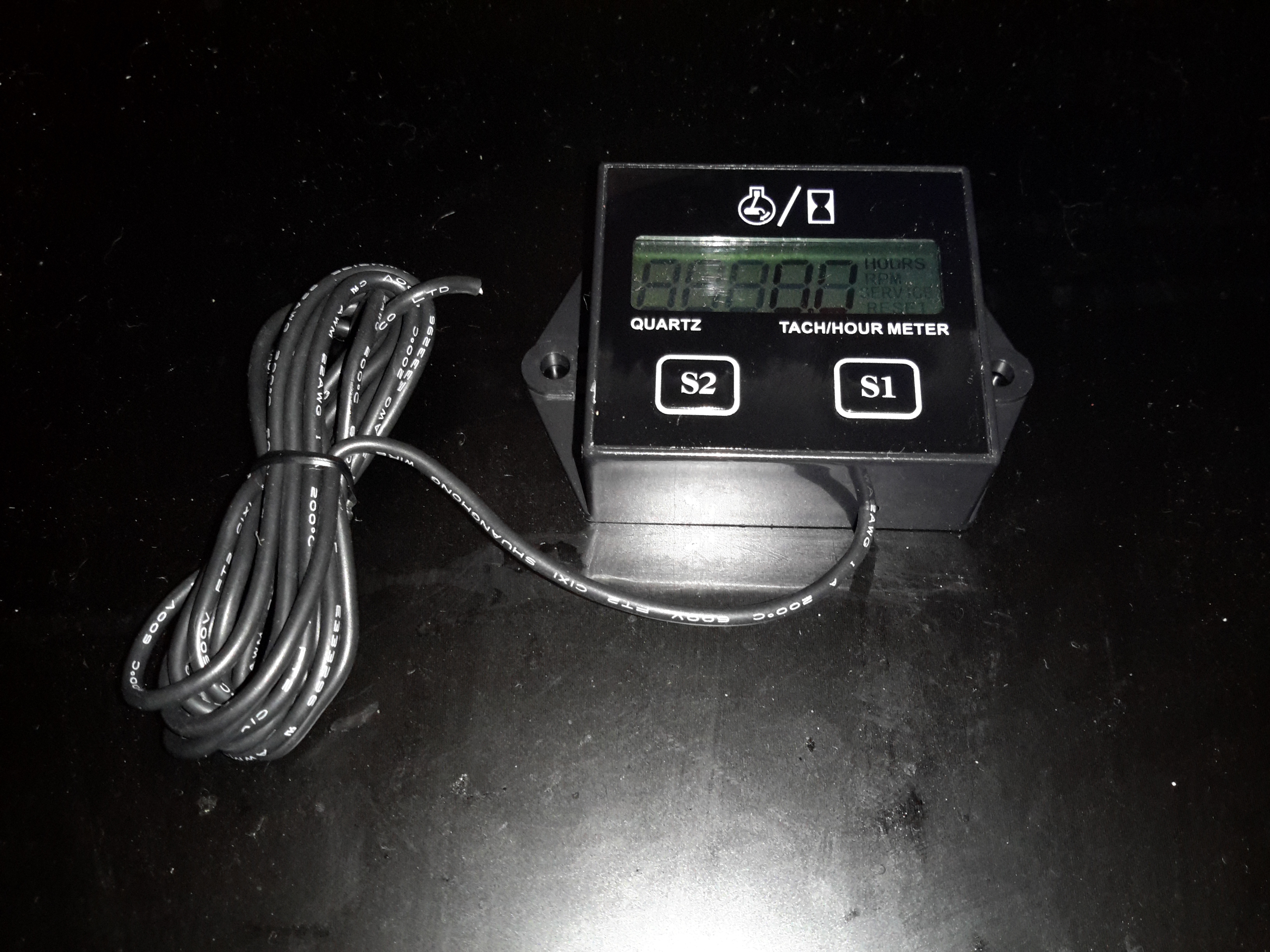
As one of my current projects involves a small petrol engine – a Honda GX35 clone, I figured an hour counter would be very handy to keep an eye on service intervals. (More to come on the engine itself later on). I found a device that would suit my needs on good old eBay.

Inductive Engine Monitor

These engine monitors are pretty cheap, at about £4. The sensing is done by a single heat-resistant silicone wire, that wraps around the HT lead to the spark plug. The unit can be set for different firing intervals via the buttons. In the case of most single-cylinder 4-stroke engines, the spark plug fires on every revolution – wasted-spark ignition. This simplifies the ignition system greatly, by not requiring the timing signal be driven from 1/2 crankshaft speed. The second “wasted” spark fires into the exhaust stroke, so has no effect.

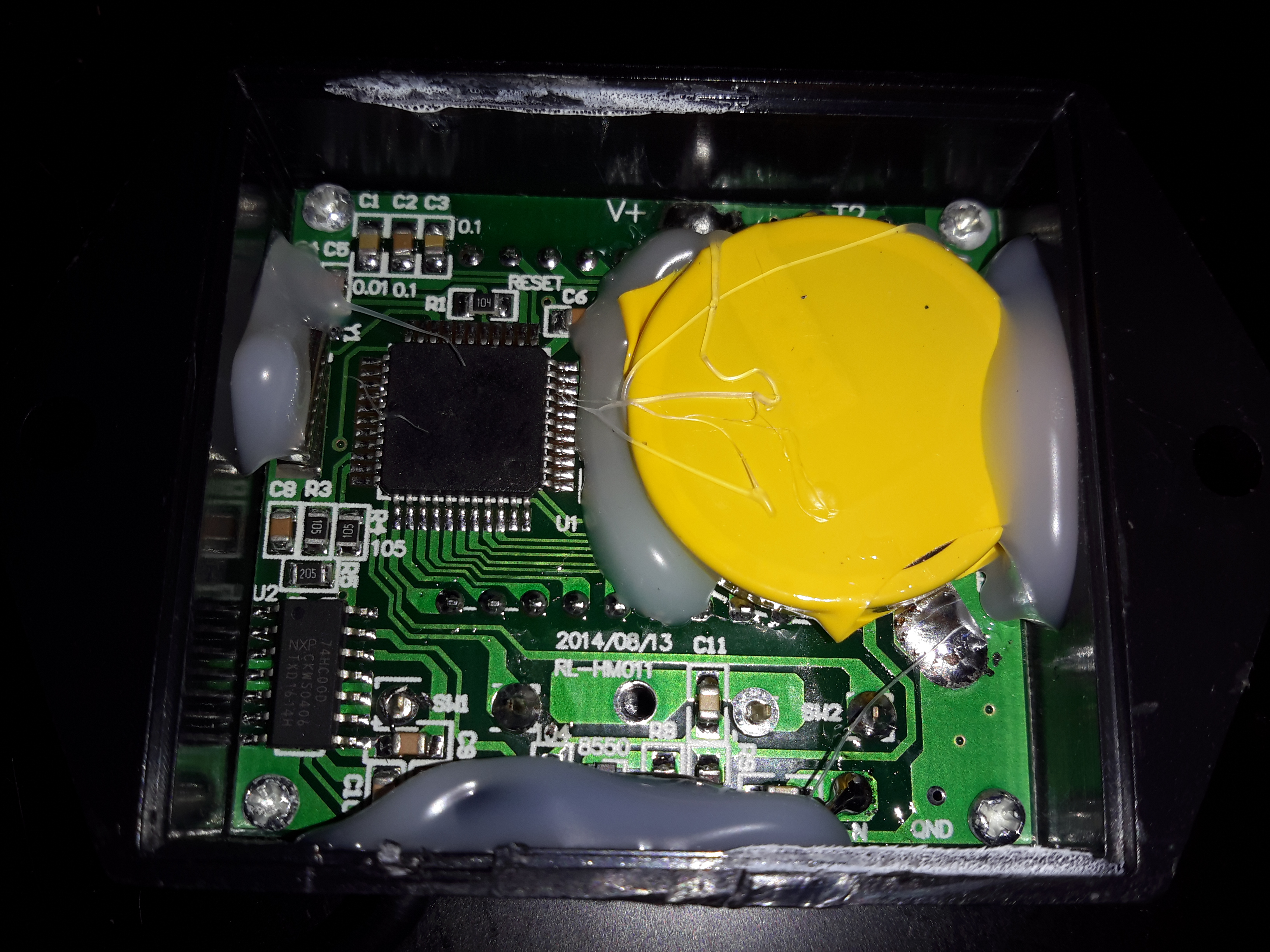
Internals
Internals

The back cover is lightly glued into place with a drop of cyanoacrylate in opposite corners, but easily pops off. The power is supplied by a soldered-in 3v Lithium cell. The main microcontroller has no number laser etched on to it at all – it appears it skipped the marking machine.

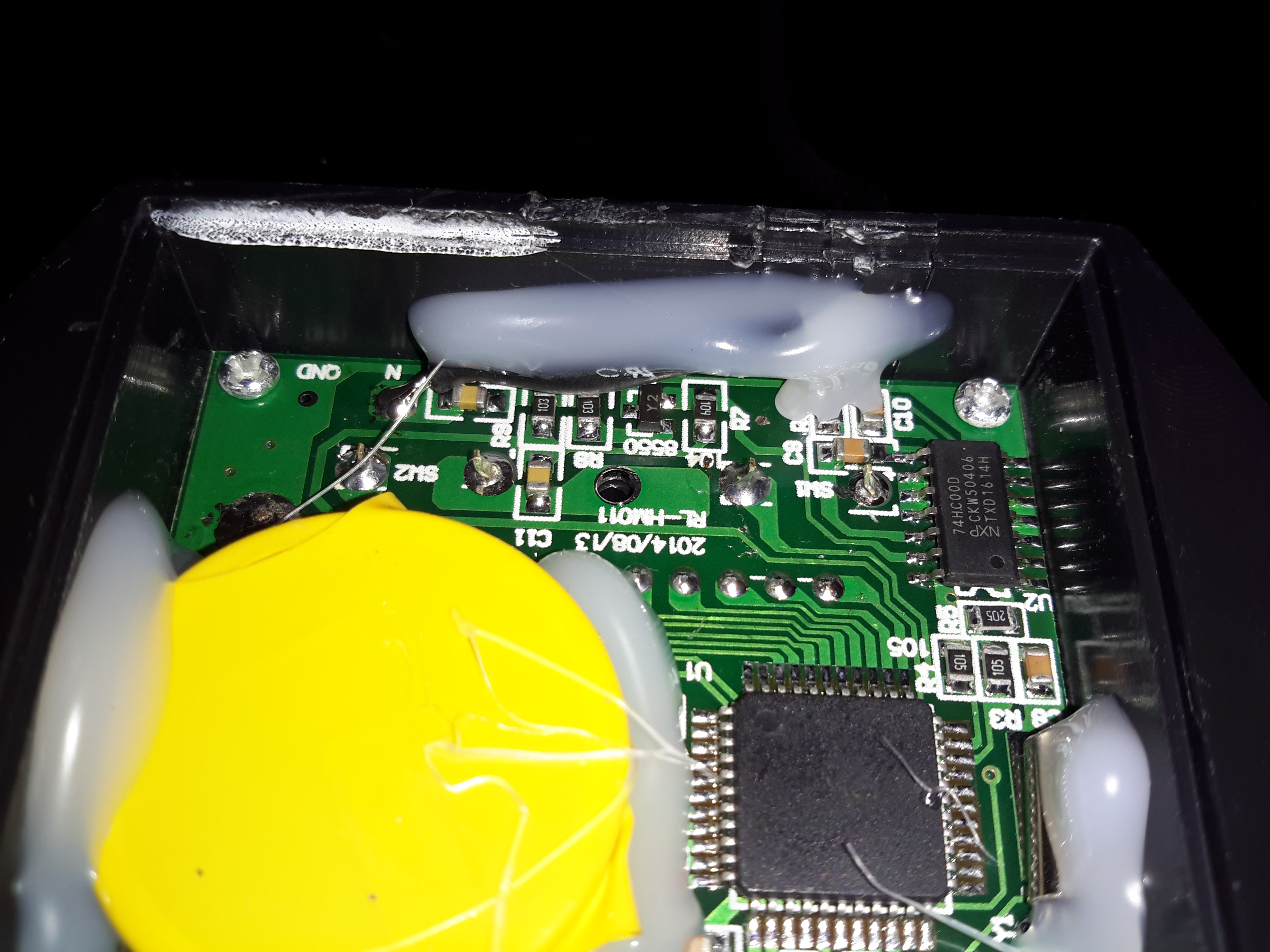
Input Filtering
Input Filtering

The input from the sensing wire comes in through a coupling capacitor & is amplified by a transistor. It’s then fed into a 74HC00D Quad 2-Input NAND gate, before being fed into the microcontroller.

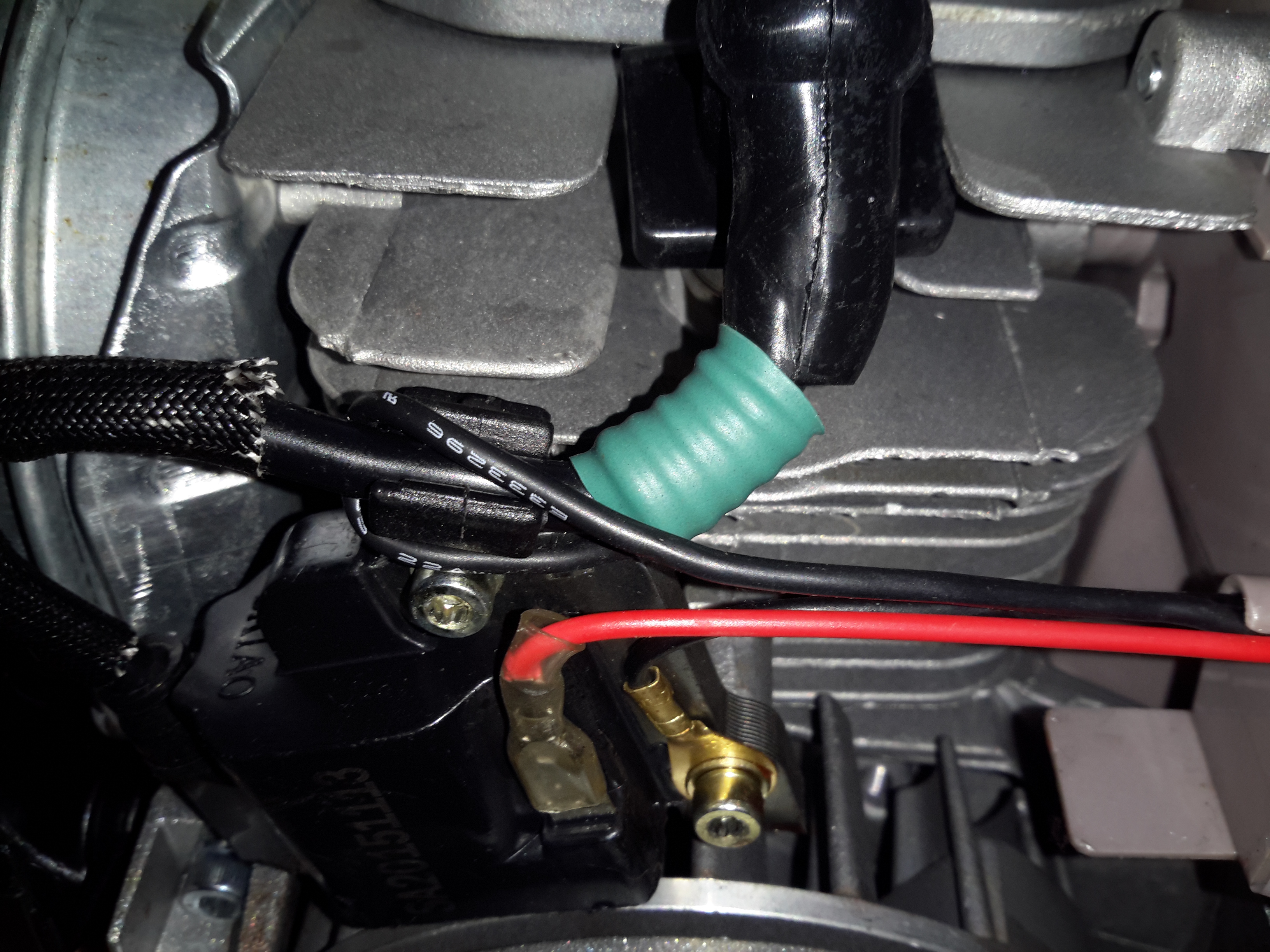
Pickup
Pickup

The pickup wire is simply wound around the spark plug lead. I’ve held it in position here with some heatshrink tubing. Heat in this area shouldn’t be an issue as it’s directly in the airflow from the flywheel fan.

He-Ne Laser Safety

As with *any* laser, proper precautions must be taken to avoid any possibility of damage to vision. The types of He-Ne lasers mostly dealt with in this document are rated Class II, IIIa, or the low end of IIIb (see the section: Laser Safety Classifications. For most of these, common sense (don’t stare into the beam) and fairly basic precautions suffice since the reflected or scattered light will not cause instantaneous injury and is not a fire hazard.

However, unlike those for laser diodes, He-Ne power supplies utilize high voltage (several kV) and some designs may be potentially lethal. This is particularly true of AC line powered units since the power transformer may be capable of much more current than is actually required by the He-Ne laser tube – especially if it is home built using the transformer from some other piece of equipment (like an old tube type console TV or that utility pole transformer you found along the curb) which may have a much higher current rating.

The high quality capacitors in a typical power supply will hold enough charge to wake you up – for quite a while even after the supply has been switched off and unplugged. Depending on design, there may be up to 10 to 15 kV or more (but on very small capacitors) if the power supply was operated without a He-Ne tube attached or it did not start for some reason. There will likely be a lower voltage – perhaps 1 to 3 kV – on somewhat larger capacitors. Unless significantly oversized, the amount of stored energy isn’t likely to be enough to be lethal but it can still be quite a jolt. The He-Ne tube itself also acts as a small HV capacitor so even touching it should it become disconnected from the power supply may give you a tingle. This probably won’t really hurt you physically but your ego may be bruised if you then drop the tube and it then shatters on the floor!

However, should you be dealing with a much larger He-Ne laser, its power supply is going to be correspondingly more dangerous as well. For example, a 35 mW He-Ne tube typically requires about 8 mA at 5 to 6 kV. That current may not sound like much but the power supply is likely capable of providing much more if you are the destination instead of the laser head (especially if it is a home-made unit using grossly oversized parts)! It doesn’t take much more under the wrong conditions to kill.

After powering off, use a well insulated 1M resistor made from a string of ten 100K, 2 W metal film resistors in a glass or plastic tube to drain the charge – and confirm with a voltmeter before touching anything. (Don’t use carbon resistors as I have seen them behave funny around high voltages. And, don’t use the old screwdriver trick – shorting the output of the power supply directly to ground – as this may damage it internally.)

And only change electrical connections or plug/unplug connectors with power OFF, being aware of the potential for stored charge. In particular, the aluminium cylinder of some HeNe laser heads is the negative return for the tube current via a spring contact inside the rear end-cap. So, pulling off the rear end-cap while the laser is powered will likely make YOU the negative return instead! You will probably then bounce off the ceiling while the laser bounces off the floor, which can easily ruin your entire day in more ways than one. 🙁 🙂 This connection scheme is known to be true for most JDS Uniphase and many Melles Griot laser heads, but may apply to others as well.

Now, for some first-hand experience:

(From: Doug (dulmage@skypoint.com).)

Well, here’s where I embarrass myself, but hopefully save a life…

I’ve worked on medium and large frame lasers since about 1980 (Spectra-Physics 168’s, 171’s, Innova 90’s, 100’s and 200’s – high voltage, high current, no line isolation, multi-kV igniters, etc.). Never in all that time did I ever get hurt other than getting a few retinal burns (that’s bad enough, but at least I never fell across a tube or igniter at startup). Anyway, the one laser that almost did kill me was also the smallest that I ever worked on.

I was doing some testing of AO devices along with some small cylindrical HeNe tubes from Siemens. These little coax tubes had clips for attaching the anode and cathode connections. Well, I was going through a few boxes of these things a day doing various tests. Just slap them on the bench, fire them up, discharge the supplies and then disconnect and try another one. They ran off a 9 VDC power supply.

At the end of one long day, I called it quits early and just shut the laser supply off and left the tube in place as I was just going to put on a new tube in the morning. That next morning, I came and incorrectly assumed that the power supply would have discharged on it own overnight. So, with each hand I stupidly grab one clip each on the laser to disconnect it. YeeHaaaaaaaaa!!!!. I felt like I had been hid across my temples with a two by four. It felt like I swallowed my tongue and then I kind of blacked out. One of the guys came and helped me up, but I was weak in the knees, and very disoriented.

I stumbled around for about 15 minutes and then out of nowhere it was just like I got another shock! This cycle of stuff went on for about 3 hours, then stopped once I got to the hospital. I can’t even remember what they did to me there. Anyway, how embarrassing to almost get killed by a HeNe laser after all that other high power stuff that I did. I think that’s called ‘irony’.

Comments on HeNe Laser Safety Issues

(Portions from: Robert Savas (jondrew@mail.ao.net).)

A 10 mw HeNe laser certainly presents an eye hazard.

According to American National Standard, ANSI Z136.1-1993, table 4 Simplified Method for Selecting Laser Eye Protection for Intrabeam Viewing, protective eyewear with an attenuation factor of 10 (Optical Density 1) is required for a HeNe with a 10 milliwatt output. This assumes an exposure duration of 0.25 to 10 seconds, the time in which they eye would blink or change viewing direction due the uncomfortable illumination level of the laser. Eyeware with an attenuation factor of 10 is roughly comparable to a good pair of sunglasses (this is NOT intended as a rigorous safety analysis, and I take no responsibility for anyone foolish enough to stare at a laser beam under any circumstances). This calculation also assumes the entire 10 milliwatts are contained in a beam small enough to enter a 7 millimeter aperture (the pupil of the eye). Beyond a few meters the beam has spread out enough so that only a small fraction of the total optical power could possible enter the eye.
Posted on Leave a comment

Another Chinese Charger

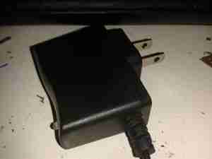
I almost forgot about this bit of kit, that came with one of my LED torches as a Lithium Ion charger. As I never plug in anything that comes from China via eBay, here’s the teardown & analysis.

Another Lethal Charger?

Here’s the unit itself. It’s very light, and is clearly intended for American NEMA power points.

Specs
Specs

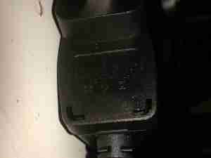
Claimed specifications are 100-240v AC input, making it universal, and 4.2v DC out ±0.5v at 500mA.
Considering the size of the output wire, if this can actually output rated voltage at rated current I’ll be surprised.

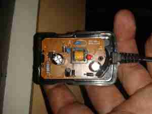
Opened
Opened

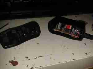
Here’s the adaptor opened up. There’s no mains wiring to speak of, the mains pins simply push into tags on the PCB.

PCB Top
PCB Top

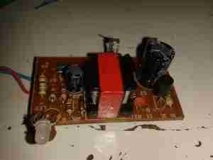
Top of the SMPS PCB. As usual with Chinese gear, it’s very simple, very cheap and likely very dangerous. There’s no real fusing on the mains input, only half-wave rectification & no EMI filtering.

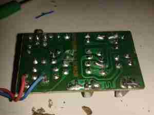
PCB Bottom
PCB Bottom

Here’s the bottom of the PCB. At least there’s a fairly sized gap between the mains & the output for isolation. The wiggly bit of track next to one of the mains input tags is supposed to be a fuse – I somehow doubt that it has the required breaking characteristics to actually pass any safety standards. Obviously a proper fuse or fusible resistor was far too expensive for these.
The output wiring on the left is thinner than hair, I’d say at least 28AWG, and probably can’t carry 500mA without suffering extreme volt drop.
Posted on Leave a comment

Lethal Chinese Mains Adaptors

With every piece of Chinese electronics I obtain, mainly Baofeng radios, they come with a Europlug-type power adaptor, and a universal plug adaptor for the mains.

The charger units aren’t too bad, there’s a fair amount of isolation between the primary & secondary, and even though they’re very simple & cheap, I can’t see any immediate safety problems with them.

The plug adaptors, however, are a different matter. These things are utterly lethal!

Baofeng PSU
Baofeng PSU

Here’s the inside of the PSU. It’s just a very simple SMPS, giving an output of 10v 500mA. The fuse is actually a fusible resistor.

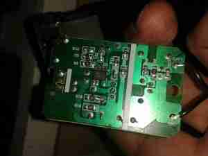
PCB Reverse
PCB Reverse

Here’s the back of the PCB with the SMPS control IC. I can’t find any English datasheets for this part unfortunately.

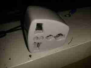
Universal Travel Adaptor

Here’s the dangerous adaptor. There’s no safety shield, so the live parts are exposed.

Internals
Internals

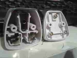
Here’s the adaptor split apart. The output contacts are on the left, and rely just on pressure to make contact with the brass screws on the mains input pins to provide power.
This is a very poor way to get a connection, a dirty or worn contact here would create a lot of heat if any significant power is pulled through, and could quite possibly result in a fire.

Not surprisingly, I bin these things as soon as I open the box, and charge all my radios with a 12v charging system.

Posted on Leave a comment

HPI Nitrostar F4.6 Ignition Conversion

As there was no other online example of someone converting a glow/nitro car engine onto CDI ignition, I thought I would document the highlights here.
The engine is currently still running on glow fuel, but when the required fuel lines arrive I will be attempting the switch over to 2-Stroke petrol mix. This should definitely save on fuel costs.

The engine in this case is a HPI NitroStar F4.6 nitro engine, from a HPI Savage X monster truck.

F4.6 Engine
F4.6 Engine

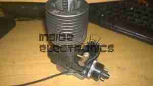
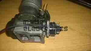
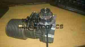
Above is the converted engine with it’s timing sensor. As The installation of this was pretty much standard, a complete strip down of the engine was required to allow the drilling & tapping of the two M3x0.5 holes to mount the sensor bracket to. The front crankshaft bearing has to be drifted out of the crankcase for this to be possible.

Ignition Hall Sensor

Detail of the ignition hall sensor. The bracket has to be modified to allow the sensor to face the magnet in the flywheel. Unlike on an Aero engine, where the magnet would be on the outside edge of the prop driver hub, in this case the hole was drilled in the face of the flywheel near the edge & the magnet pressed in. The Hall sensor is glued to the modified bracket with the leads bent to position the smaller face towards the back of the flywheel.
The clearance from the magnet to sensor is approx. 4mm.

Flywheel Magnet
Flywheel Magnet

Detail of the magnet pressed into the flywheel. A 3.9mm hole was drilled from the back face, approx 2mm from the edge, & the magnet pressed into place with gentle taps from a mallet & drift, as I had no vice to hand.
Initial timing was a little fiddly due to the flywheel only being held on with a nut & tapered sleeve, so a timing mark can be made inside the rear of the crankcase, across the crank throw & case to mark the 28 degree BTDC point, the flywheel is then adjusted to make the ignition fire at this point, before carefully tightening the flywheel retaining nut to ensure no relative movement occurs.
The slots in the sensor bracket allow several degrees of movement to fine adjust the timing point once this rough location has been achieved.

1/4"-32 Spark Plug
1/4″-32 Spark Plug

Definitely the tiniest spark plug I’ve ever seen, about an inch long. Some trouble may be encountered with this on some engines – the electrodes stick out about 2mm further into the combustion chamber than a standard glow plug does. This causes the ground electrode to hit the top of the piston crown. (This happens on the HPI NitroStar 3.5 engine). The addition of another copper washer under the plug before tightening should cure this problem.

RcExl CDI Ignition Module

Ignition module. Due to the depth of the plug in the heatsink head on these engines, I will have to modify the plug cap to straighten it out, as it will not fit in this configuration.
However, ignition modules are available from HobbyKing with straight plug caps, this makes modification unnecessary

The ignition & components used on this system were obtained from JustEngines.

Posted on 3 Comments

Wearable Raspberry Pi Part 1

Overview
Overview

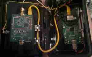
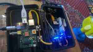
Here is the project I’m currently working on. A completely wearable computing platform based on the Raspberry Pi & the WiFi Pineapple.

Above can be seen the general overview of the current unit.

On the left:

  • Alfa AWUS036NHA USB High Power WiFi Network Interface
  • 512MB Model B Raspberry Pi, 16GB SD card, running Raspbian & LXDE Desktop. Overclocked to 1GHz.

On the right:

  • WiFi Pineapple router board
  • USB 3G card.

The WiFi, Pineapple & 3G all have external antenna connections for a better signal & the whole unit locks onto the belt with a pair of clips.
The Raspberry Pi is using the composite video output to the 7″ LCD I am using, running at a resolution of 640×480. This gives a decent amount of desktop space while retaining readability of the display.

The case itself is a Pelican 1050 hard case, with it’s rubber lining removed. The belt clips are also a custom addition.

Connections
Connections

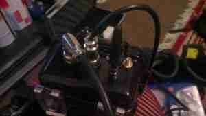
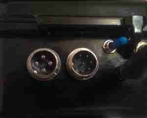
Here are the connections to the main unit, on the left is the main power connector, supplying +5v & +12v DC. The plug on the right is an 8-pin connection that carries two channels of video, mono audio & +12v power to the display.
Currently the only antenna fitted is the 3G.

Connectors
Connectors

Closeup of the connections for power, audio & video. The toggle switch is redundant & will soon be replaced with a 3.5mm stereo jack for headphones, as an alternative to the mono audio built into the display.

Test Run
Test Run

Current state of test. Here the unit is running, provided with an internet connection through the Pineapple’s 3G radio, funneled into the Pi via it’s ethernet connection.

Pi Goodness!
Pi Goodness!

Running on a car reversing camera monitor at 640×480 resolution. This works fairly well for the size of the monitor & the text is still large enough to be readable.


Stay tuned for Part 2 where I will build the power supply unit.


Posted on Leave a comment

Tool-less UK Mains Plug

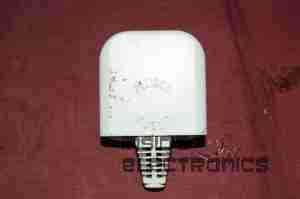
Plug Bottom
Plug Bottom

This is a standard 13A UK main power plug – with a twist. This one requires no tools to open or connect.
The top cover is slid off the top, after turning the red cam with a coin to unlock it.

Plug Top
Plug Top

Manufactured by Plugco – a Google search of this company returns no results.

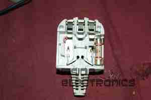
Cover Removed
Cover Removed

Top cover removed from the plug, as is standard with UK mains plugs the live conductor is fused – 3A in this case. The conductors are clamped into the fittings in a row along the top edge of the plug.

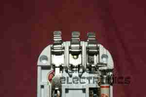
Wire Clamps
Wire Clamps

Closeup of the wire clamps. Conductor is placed in the slot & snapped closed.

This is an old plug & they do not appear to be available these days, for unknown reasons. Being able to change a plug without a screwdriver has it’s advantages 🙂

Posted on Leave a comment

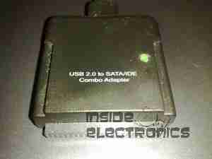
USB-IDE/SATA Adaptor

Front
Front

This is a device to use an IDE or SATA interface drive via a USB connection. Here is the front of the device, IDE interface at the bottom, 2.5″ form factor.

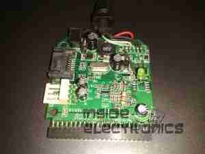
PCB Top
PCB Top

PCB removed from the casing. USB cable exits the top, 12v DC power jack to the left.
SATA interface below the DC Jack.
Molex connector below SATA is the power output for the drive in use. This unit has a built in 5v regulator.

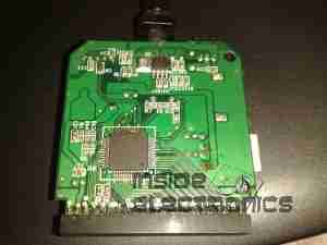
PCB Bottom
PCB Bottom

Bottom of the PCB showing the interface IC.

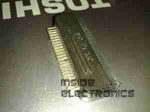
Drive Adaptor
Drive Adaptor

Adaptor to plug into the 44-pin 2.5″ form factor IDE interface on the adaptor, converts to standard 40-pin 3.5″ IDE.

Power Cable
Power Cable

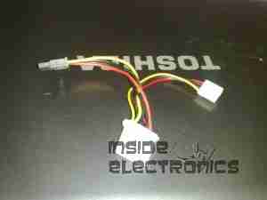
Power pigtail with standard Molex & SATA power plugs.

Posted on Leave a comment

Laser Diode Driver

Connection

Closeup
Closeup

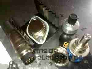
The parts arrived for my adjustable laser diode driver! Components here are an LM317K with heatsink, 100Ω 10-turn precision potentiometer, 15-turn counting dial & a 7-pin matching plug & socket.

Driver Schematic
Driver Schematic

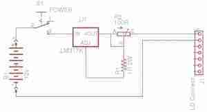
Here is the schematic for the driver circuit. I have used a 7-pin socket for provisions for active cooling of bigger laser diodes. R1 sets the maximum current to the laser diode, while R2 is the power adjustment. This is all fed from the main 12v Ni-Cd pack built into the PSU. The LM317 is set up as a constant current source in this circuit.

Installed
Installed

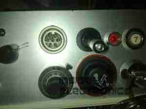
Here the power adjust dial & the laser head connector have been installed in the front panel. Power is switched to the driver with the toggle switch to the right of the connector.

Regulator
Regulator

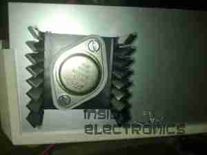
The LM317 installed on the rear panel of the PSU with it’s heatsink.

Connection
Connection

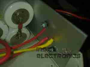
Connections to the regulator, the output is fully isolated from the heatsink & rear panel.