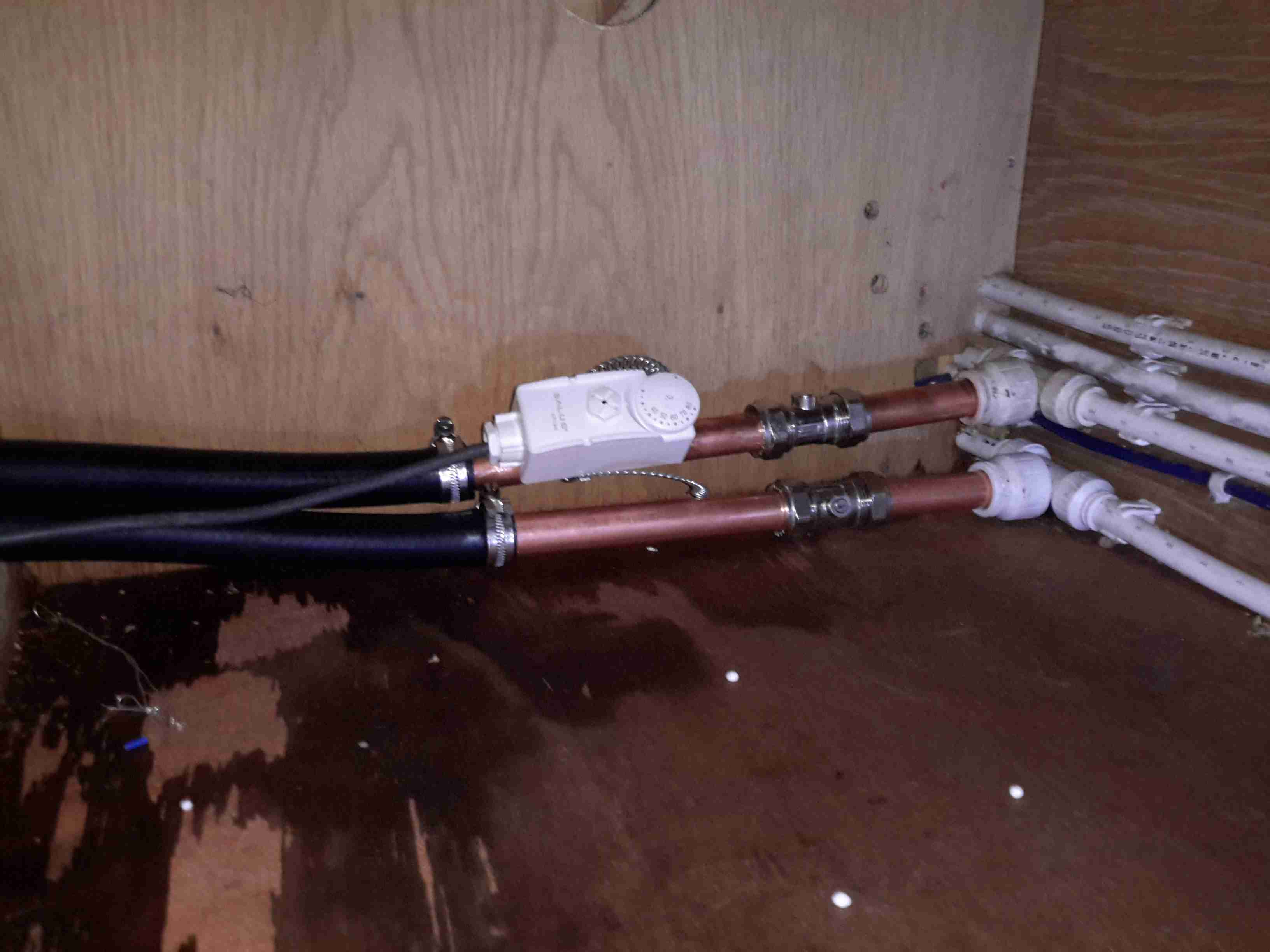
Here the pipework feeding the matrix of the blower unit has been tapped into the heating circuit, the first radiator on the loop is just out of shot to the right, this is all tucked away under the bed in one of the cabins. The pipestat is attached to the flow from the boiler, this will switch on the blower once hot water starts flowing through the system. Isolation valves have been fitted to make the inevitable maintenance of the matrix unit easier, as the system is pressurised to 14PSI, dropping the pressure out of the system without making quite a mess is difficult.
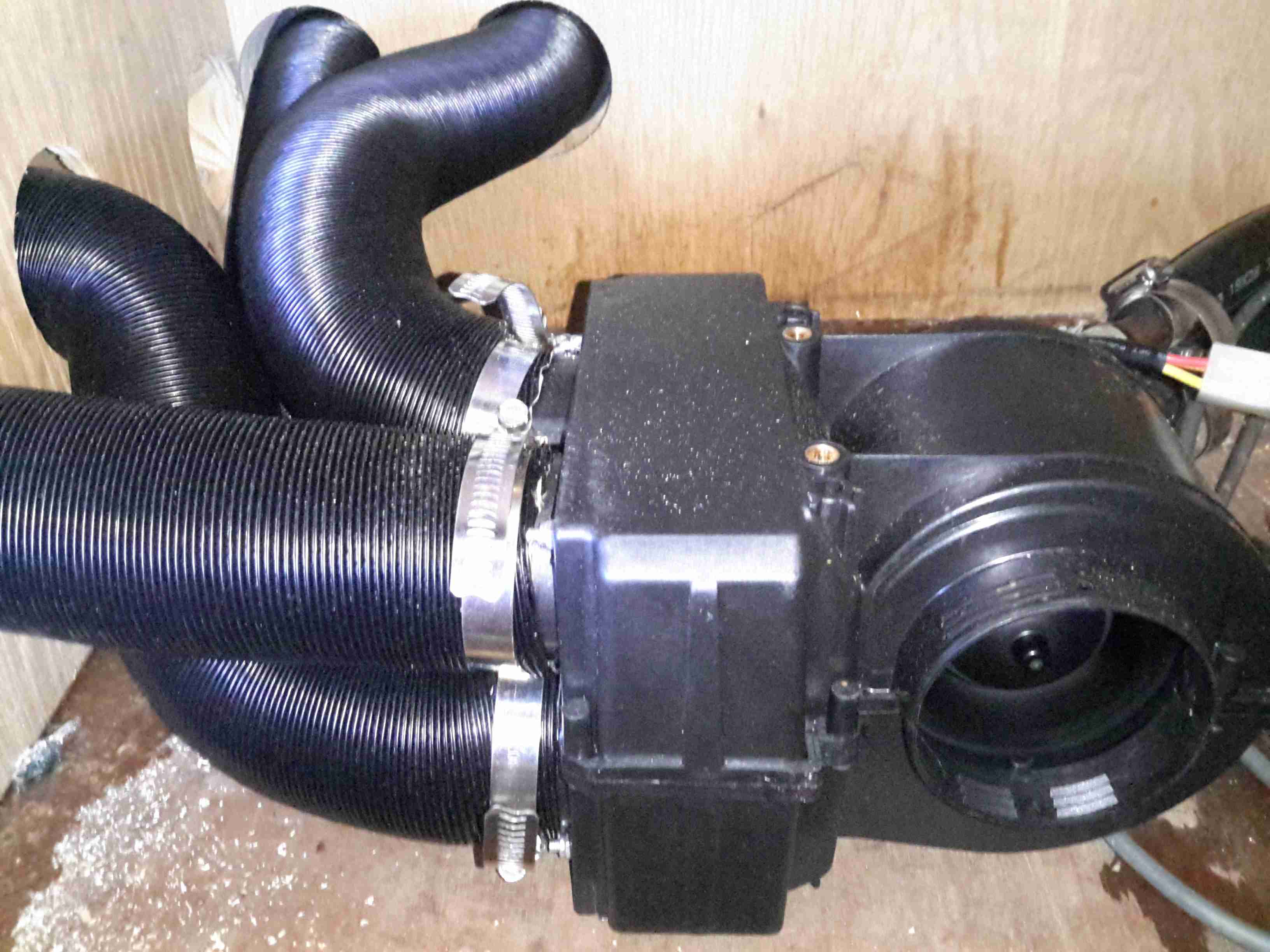
Heater Matrix & Ducting
The heater itself is mounted on the other side of a wooden partition in the small space left under a shelf. This made installing the unit like trying to plumb in a radiator through a letterbox ;). 4 60mm ducts snake off to the vents mounted in the wall.
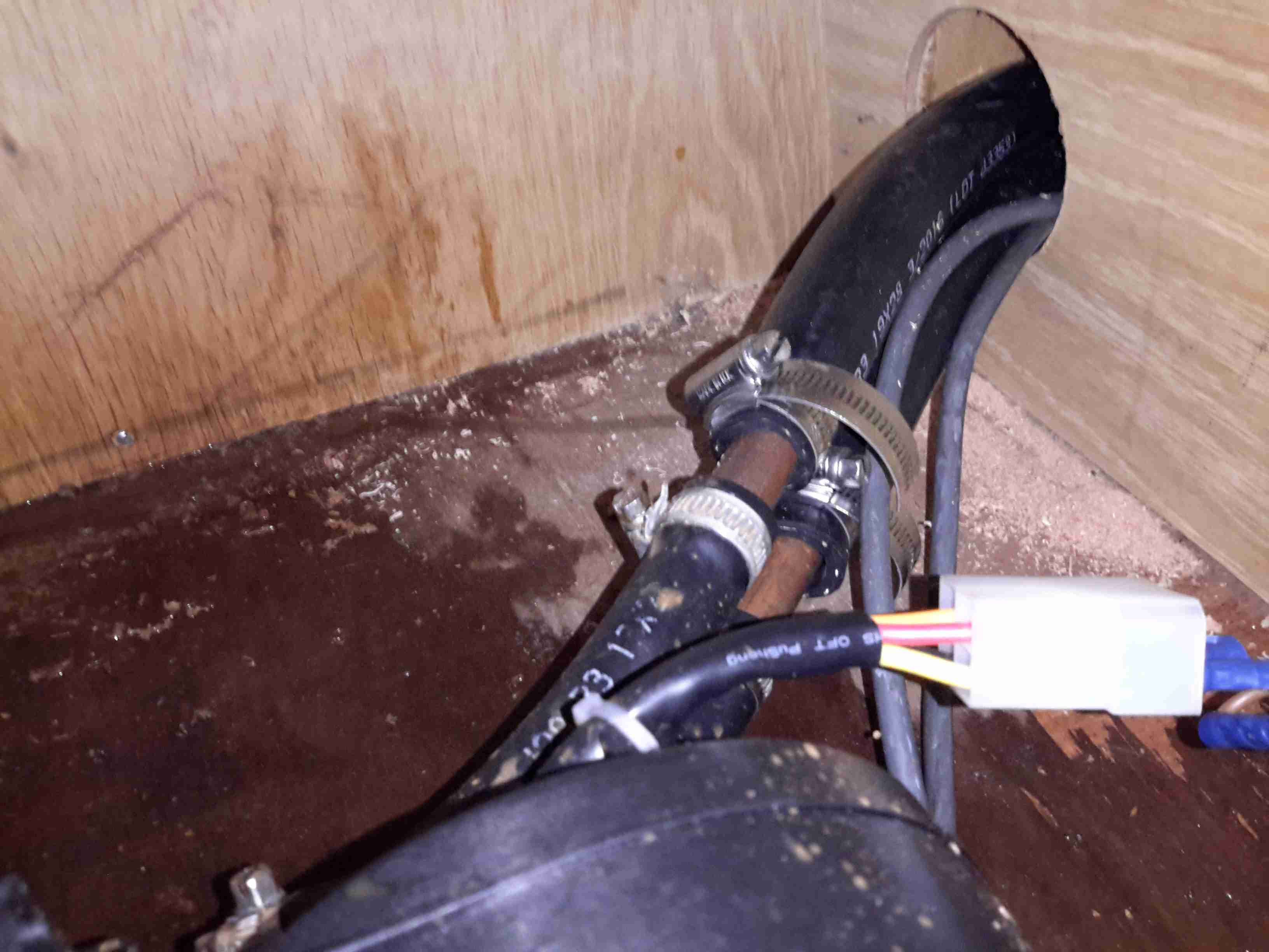
Water Connections
The hot water hoses appear through a hole in the timber to connect to the matrix unit, with some 15mm pipe in between as reducers from the 3/4″ hose to the 1/2″ attached to the matrix itself. The blower is wired in low speed mode only, as running it any faster makes far too much noise from the vents.
As a heating solution, this unit works well onboard. Within a 10 minutes of the diesel heater firing up, the blower automatically comes on thanks to the thermostat, and blows plenty of hot air into the saloon to keep the cold at bay.
Going through eBay recently looking for parts for a couple of CRT-based projects, I came across these DC-DC converters.
Apparently rated from 45-390v DC output at 200mA, these should be ideal for driving some of the electrodes (focus, screen, grid) in a CRT.
Above is the top of the board, input voltage header on the left, output voltage adjust in the centre & output voltage header on the right.
This module has a mini-automotive fuse, at 10A for input protection.
On the heatsink is mounted the main switching MOSFET, a RU7088R from Ruichips. This FET is fairly heavily rated at 70v 80A, with 6.5mΩ on-resistance.
PCB Bottom
The bottom of the board has the control components, with a pair of ICs. Unfortunately the numbers have been scrubbed off, so no identification here. The output from the transformer is rectified with a single large SMD diode on the left side of the board.
There’s also plenty of isolation gap between the HV output trace & the low voltage logic side of the circuit, the two being bridged only by a resistive divider for output voltage measurement.
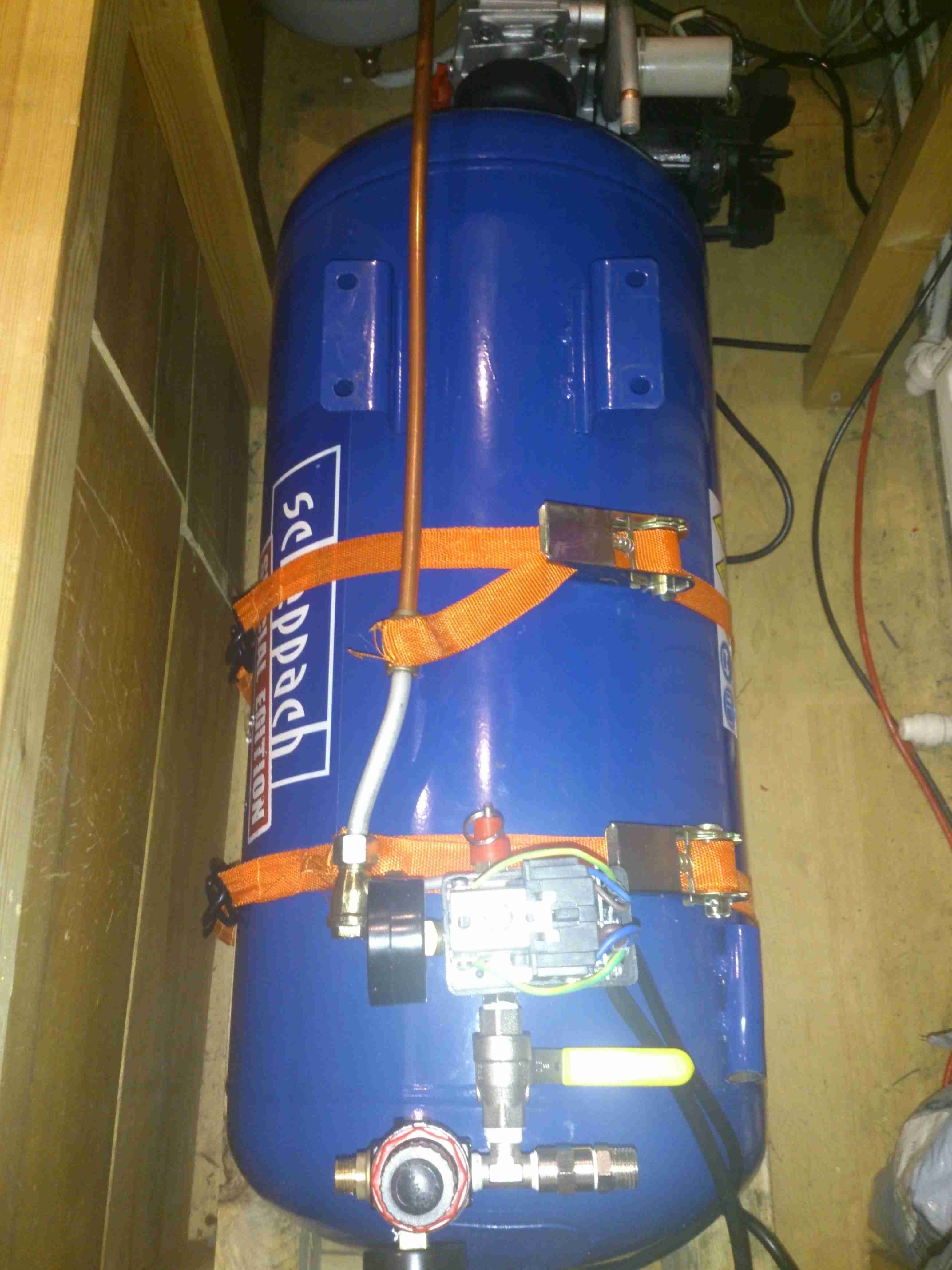
Compressed air is a rather useful power source, especially when all maintenance is done by the on board crew instead of by boatyards.
Screwfix had a good deal on a 50L 3.5CFM air compressor, to save space this has been permanently mounted in a free space & air will be piped to where it is needed from a central point.
Because of the total height of the machine, the compressor itself has been unbolted from the tank, a copper line connecting the two back together at a larger distance.
Bearers
In one of the very few free spaces available, under a bunk. A pair of timbers has been screwed to the floor to support the tank.
Tank Installed
The tank is strapped to the wooden supports with a pair of ratchet straps, the compressor itself can be seen just behind the tank. The copper line on the top of the tank is going back to be connected to the compressor outlet.
Air Fittings
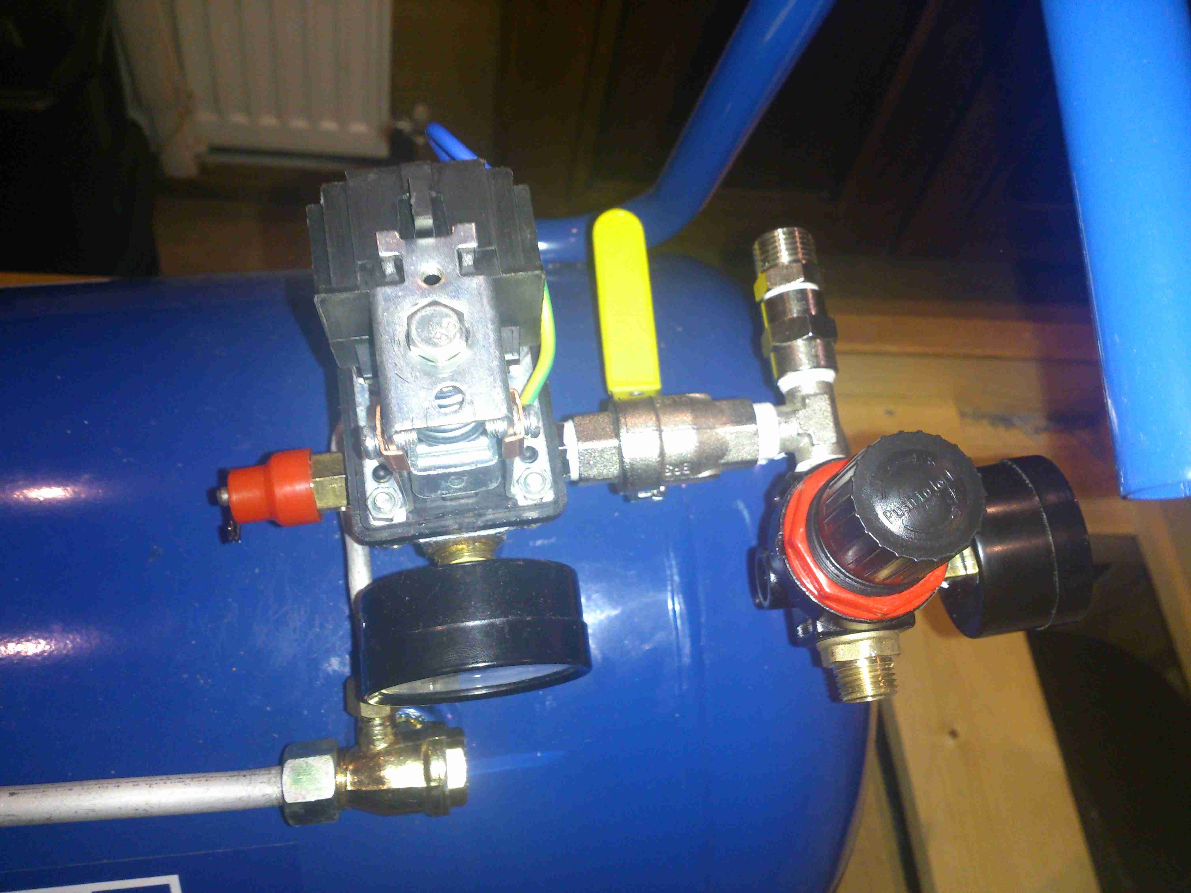
Compressor control remains on top of the tank, the pressure switch & relief valve centre. After an isolation valve, the feed splits, the regulator installed will be feeding the air horn with 20PSI, replacing the existing automotive-style 12v air pump. The currently open fitting will be routed to a quick connect on the bulkhead. This will be accessible from the front deck, an air hose can be fitted to get a supply anywhere on board.
More to come when the rest of the system gets installed!
I almost forgot about this bit of kit, that came with one of my LED torches as a Lithium Ion charger. As I never plug in anything that comes from China via eBay, here’s the teardown & analysis.
Another Lethal Charger?
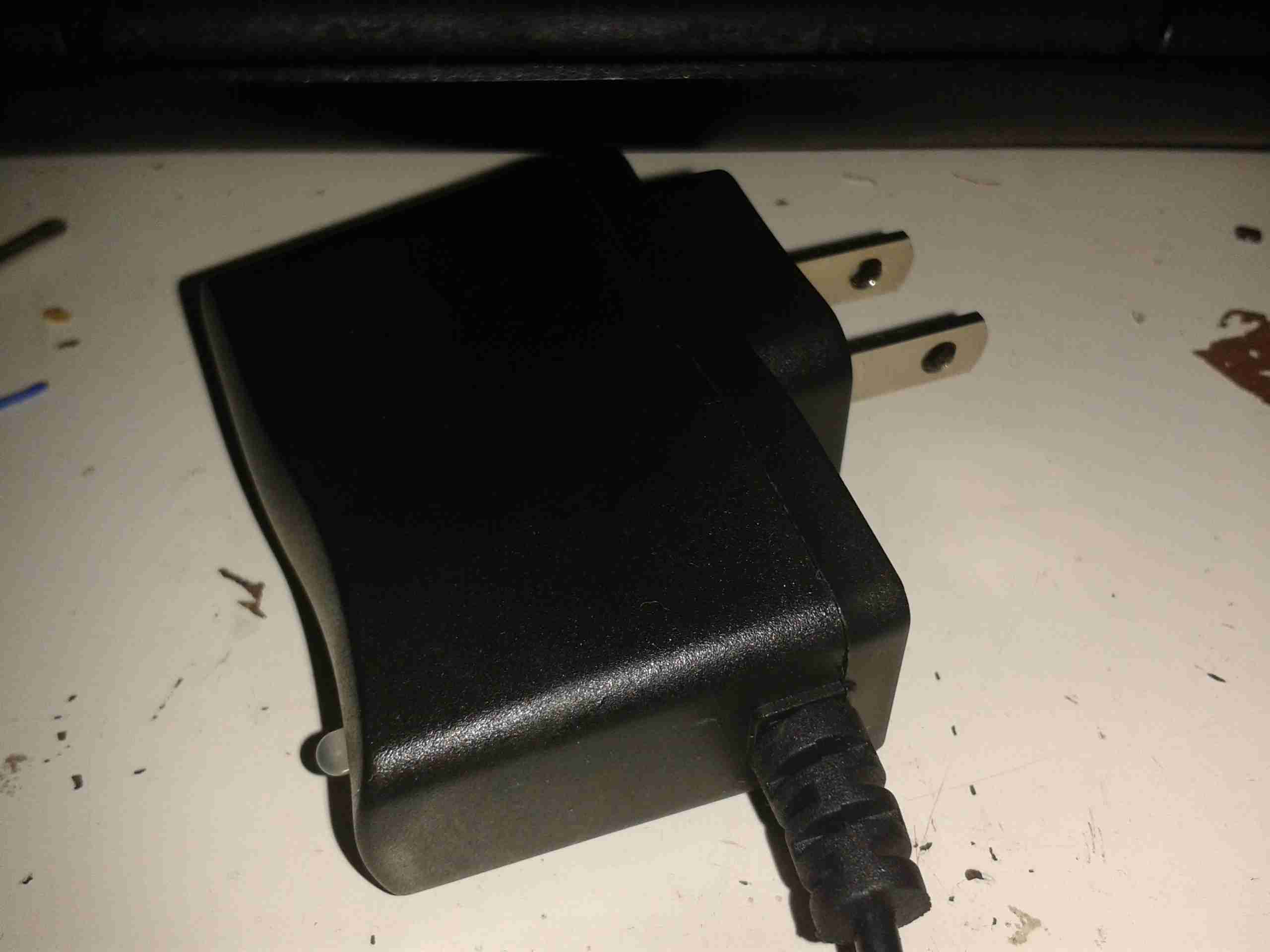
Here’s the unit itself. It’s very light, and is clearly intended for American NEMA power points.
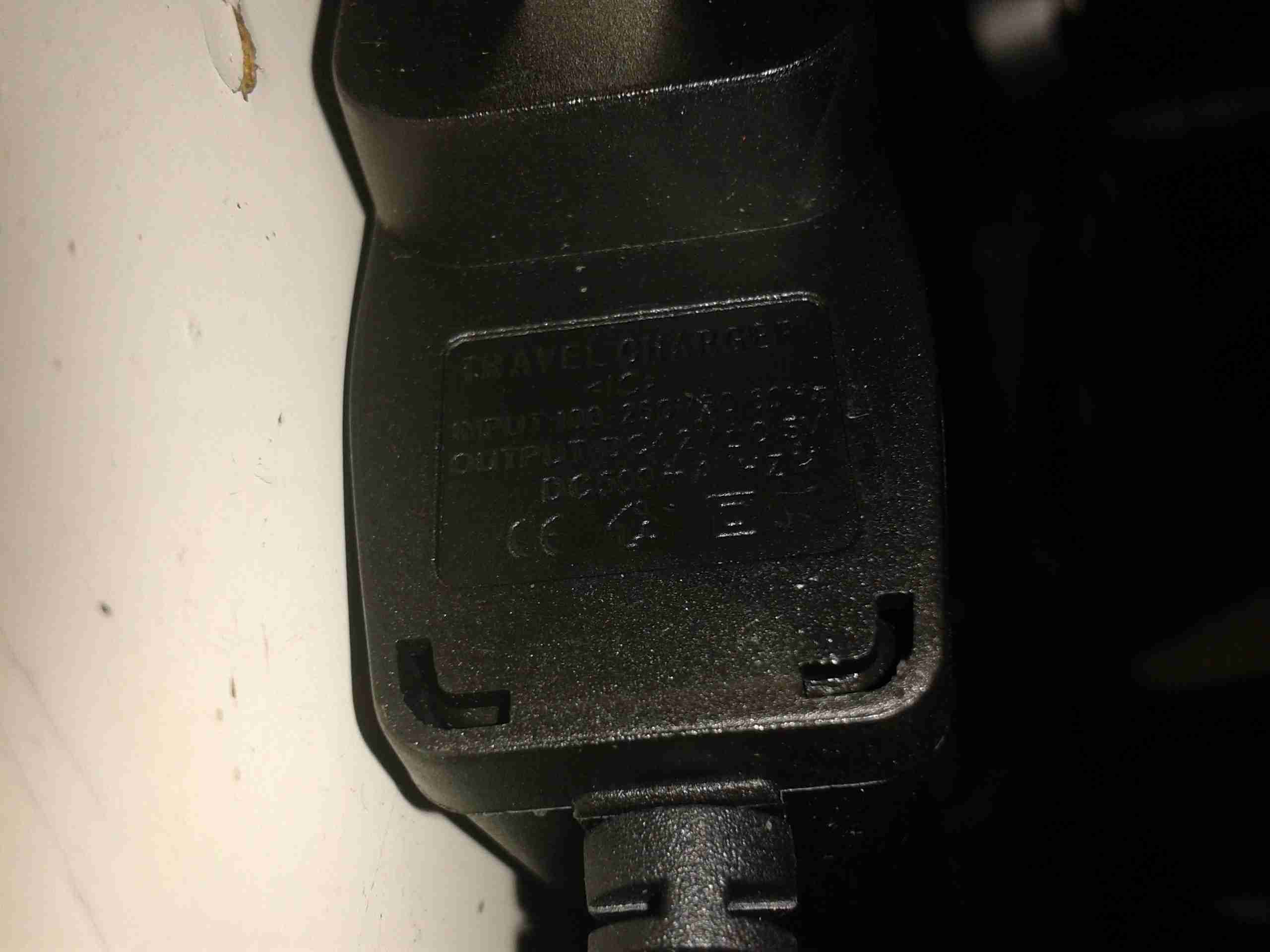
Specs
Claimed specifications are 100-240v AC input, making it universal, and 4.2v DC out ±0.5v at 500mA.
Considering the size of the output wire, if this can actually output rated voltage at rated current I’ll be surprised.
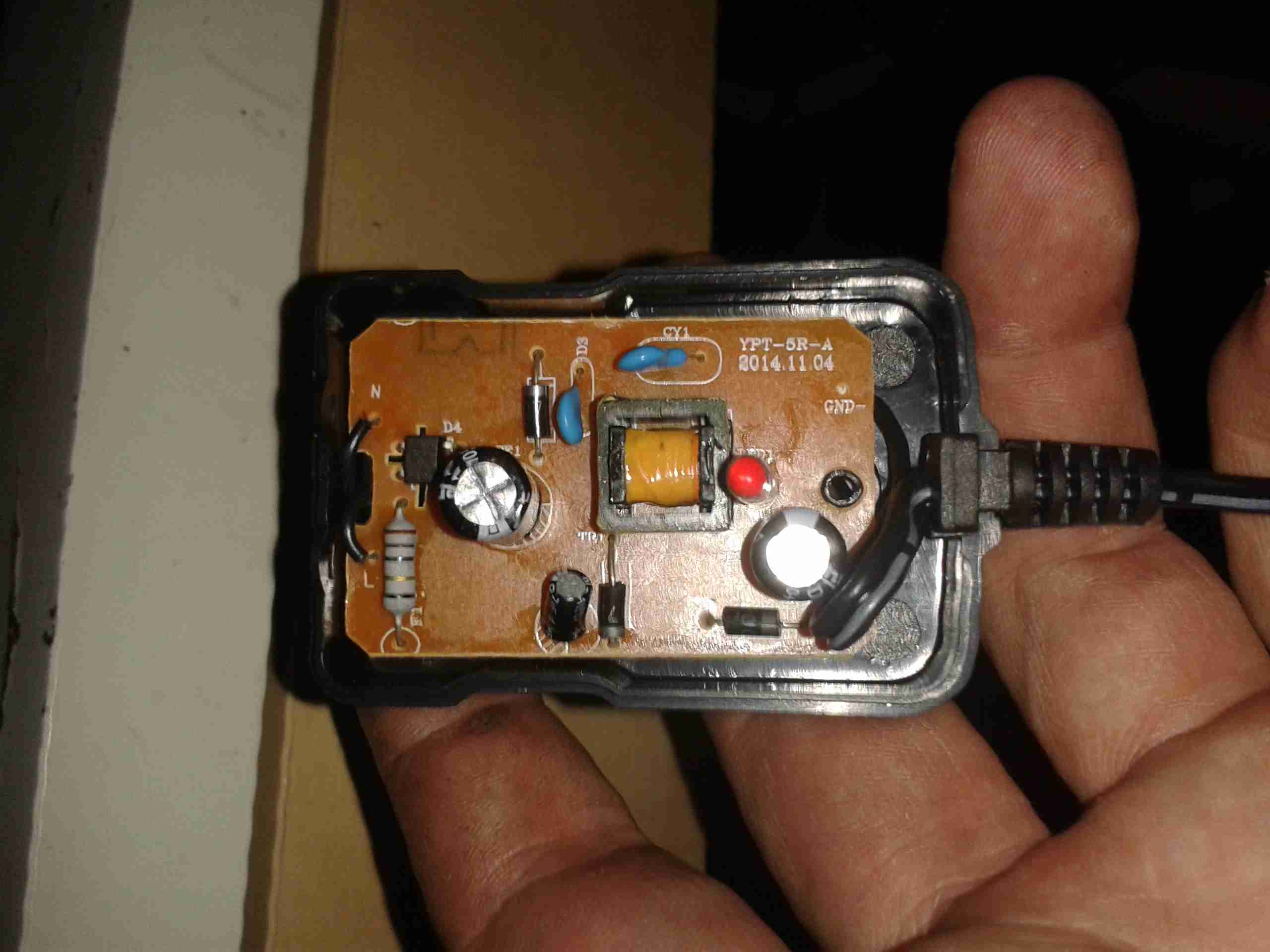
Opened
Here’s the adaptor opened up. There’s no mains wiring to speak of, the mains pins simply push into tags on the PCB.
PCB Top
Top of the SMPS PCB. As usual with Chinese gear, it’s very simple, very cheap and likely very dangerous. There’s no real fusing on the mains input, only half-wave rectification & no EMI filtering.
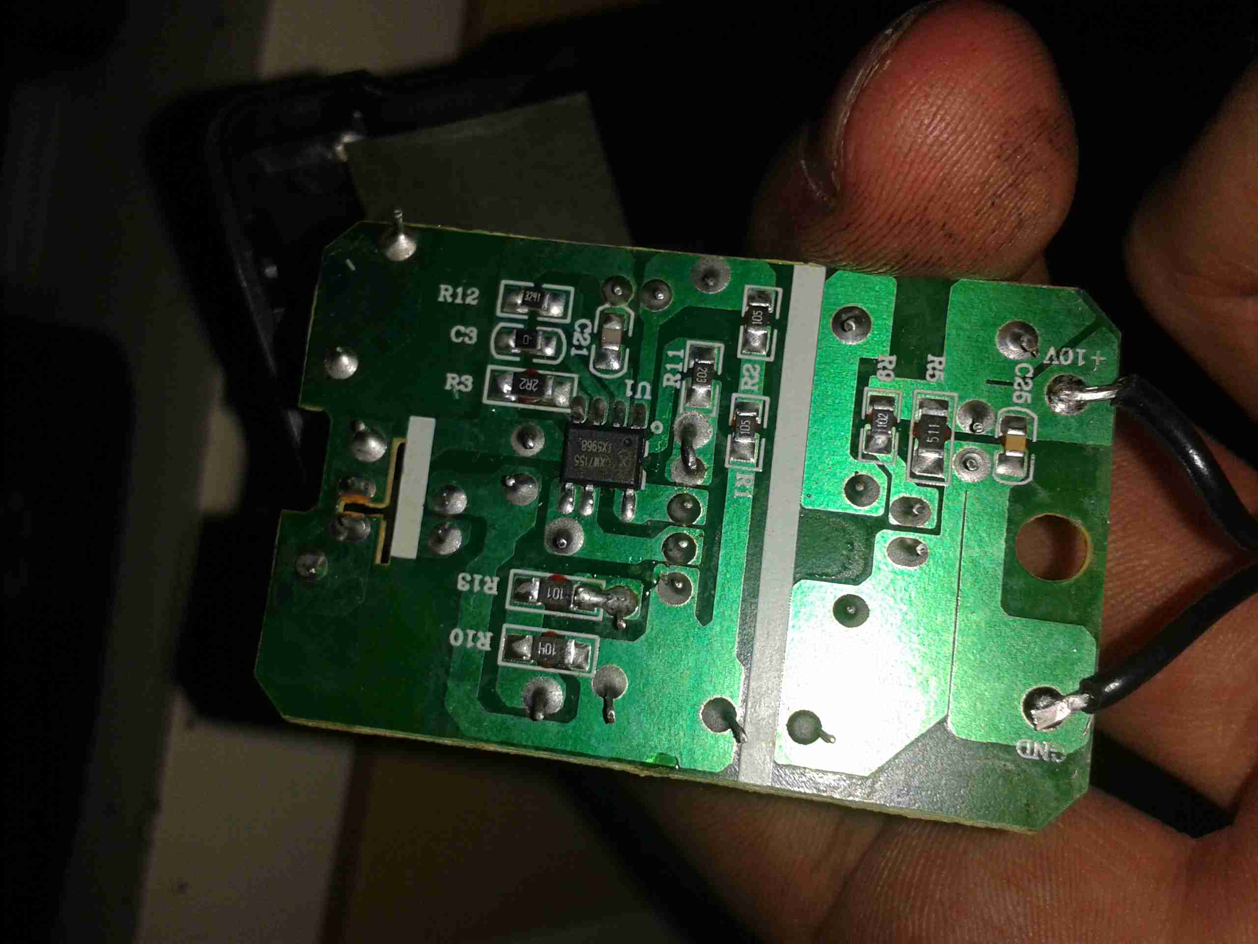
PCB Bottom
Here’s the bottom of the PCB. At least there’s a fairly sized gap between the mains & the output for isolation. The wiggly bit of track next to one of the mains input tags is supposed to be a fuse – I somehow doubt that it has the required breaking characteristics to actually pass any safety standards. Obviously a proper fuse or fusible resistor was far too expensive for these.
The output wiring on the left is thinner than hair, I’d say at least 28AWG, and probably can’t carry 500mA without suffering extreme volt drop.
Since everything in my shack is run from 12v, I thought it would be handy to convert my new scope to 12v as well, as 99% of the places I find myself needing test gear are off grid, with no access to mains supplies.
Mains PSU
Here’s the factory mains SMPS unit from the back of the scope. This is a nice multi-rail unit, with several different outputs, the table below details the wiring of the PSU.
Connector Pin
PCB Pin
Signal
Measured Voltage
Mainboard
Rectifier Rating
Wire Colour
5
1
AC_TRIG
N/A
AC_TRIG
N/A
BROWN
2
2
+9v_GND
N/A
FAN --
NA
ORANGE
11
3
+9V
10.16V
FAN +
2A
WHITE
6
4
+5V
5.1V
5V5A
20A
RED
13
5
+5V
5.1V
5V5A
20A
RED
7
6
GND
N/A
GND
N/A
BLACK
8
7
GND
N/A
GND
N/A
BLACK
3
8
+7.5V
6.9V
6.3V
20A
YELLOW
10
9
+7.5V
6.9V
6.3V
20A
YELLOW
1
10
GND
N/A
GND
N/A
BLACK
12
11
17.5V
17.51V
17.5V
2A
BLUE
9
12
-17.5V
-17.36V
-17.5V
2A
GREY
14
13
GND
N/A
GND
N/A
BLACK
4
14
-7.5V
-6.84V
-7.5V
2A
GREEN
The only feature I will lose if I make this switch is AC line triggering, but I never use that anyway, so it’s not a big issue for me.
Since I have been able to locate the connector, the plan is to design a replacement low voltage supply unit for the scope, with the same footprint as the original AC mains supply. This will allow me to do a direct swap without causing any damage or modifying the original supply.
This method will allow me to swap the 240v supply back into the scope if I ever come to need it.
I’m planning to use the LTC3863 DC-DC Controller from Linear Tech to generate the negative rails, this will go down to -150v on the output, so it’s pretty much perfect to generate them.
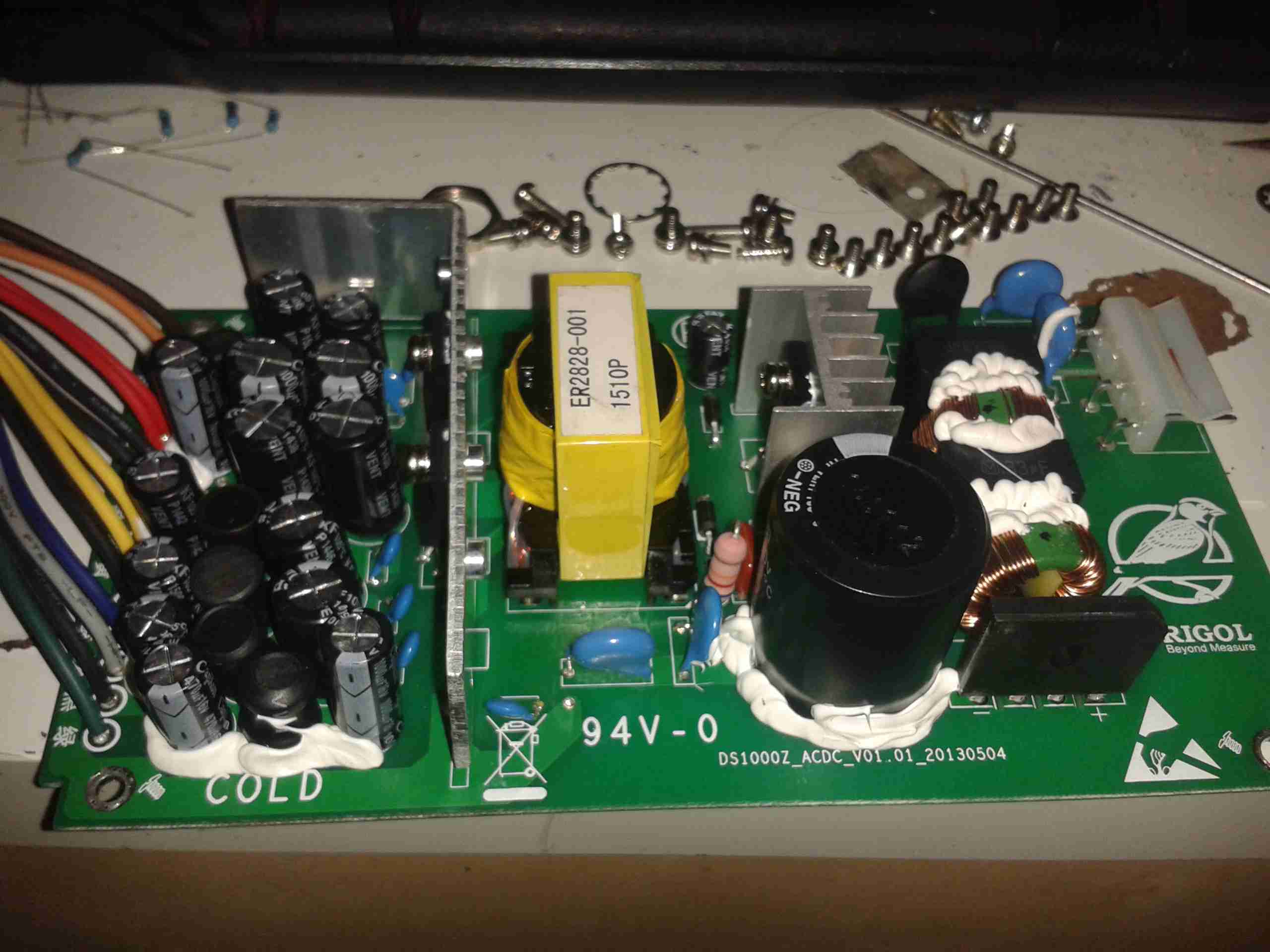
PSU Output Side
Here’s the output side of the mains PSU, it has a lot of filtering on the output rails, the two TO220 devices are the output rectifiers for the +5v & +7.5v rails, these are rated at 20A, 60V.
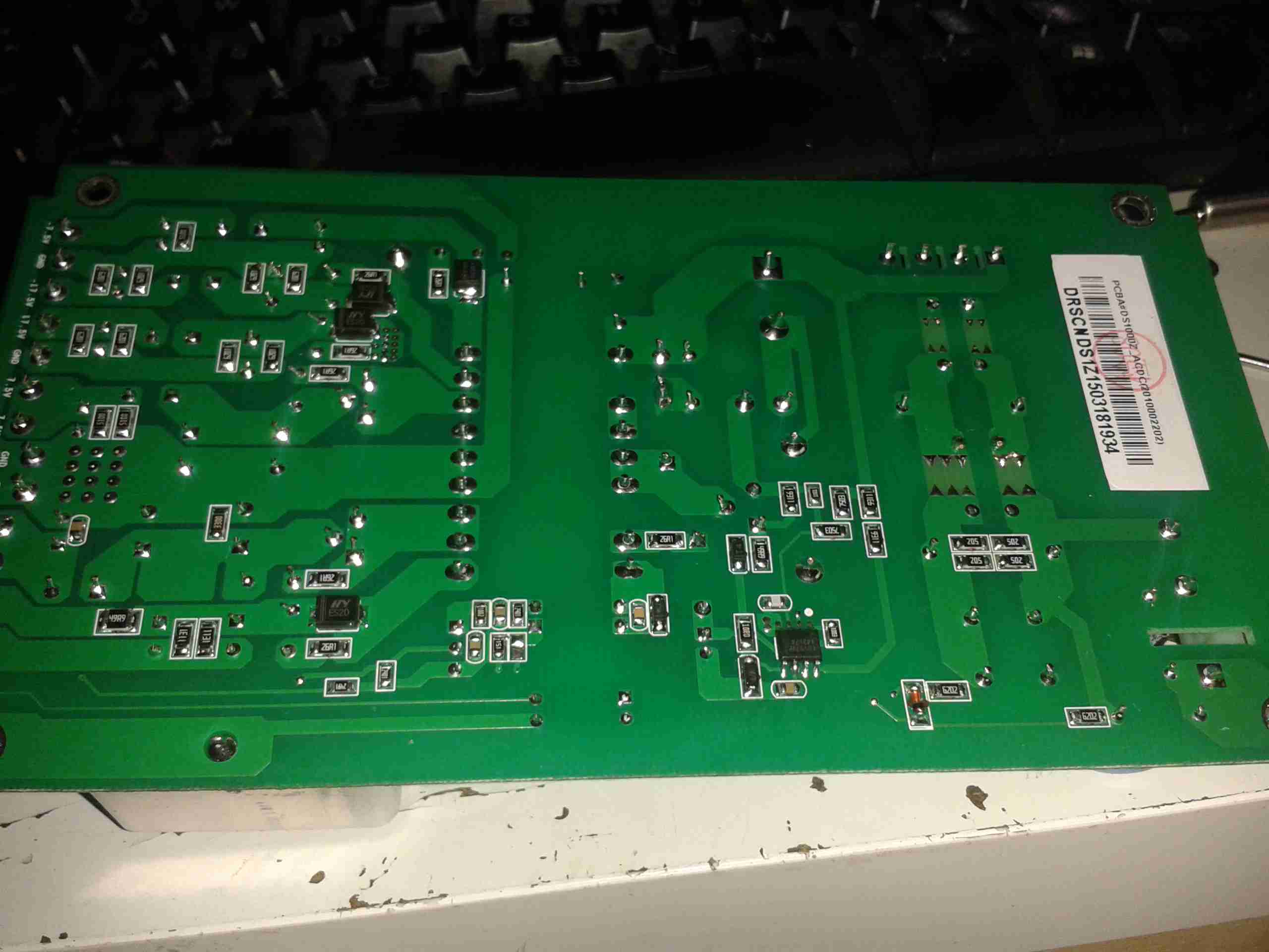
PCB Bottom
Here’s the bottom side of the PCB. It’s a really nicely designed PSU, massive isolation gap, spark gaps on the primary side & good filtering. The output side on the left has the rectifier diodes for the other voltage rails, these are only 2A rated, so designing the inverting supply to generate the negative rails will be pretty easy.
From looking at the PCB markings on both the mainboard & the PSU, the +9v rail seems to be used to drive the fan, both silkscreen markings indicate this.
The voltages marked on the PSU & the mainboard connector don’t quite match up though, there’s a small variation in the stated voltage between the two. This is most likely because all of the regulation of the supplies seems to be done on the mainboard, there are several linear regulators, and a few DC-DC switchers. Providing that the replacement supply isn’t noisy it should work fine.
This is backed up by the fact that the mains PSU only seems to regulate the +5v rail – on measuring the rails that’s the only one that’s close to spec.
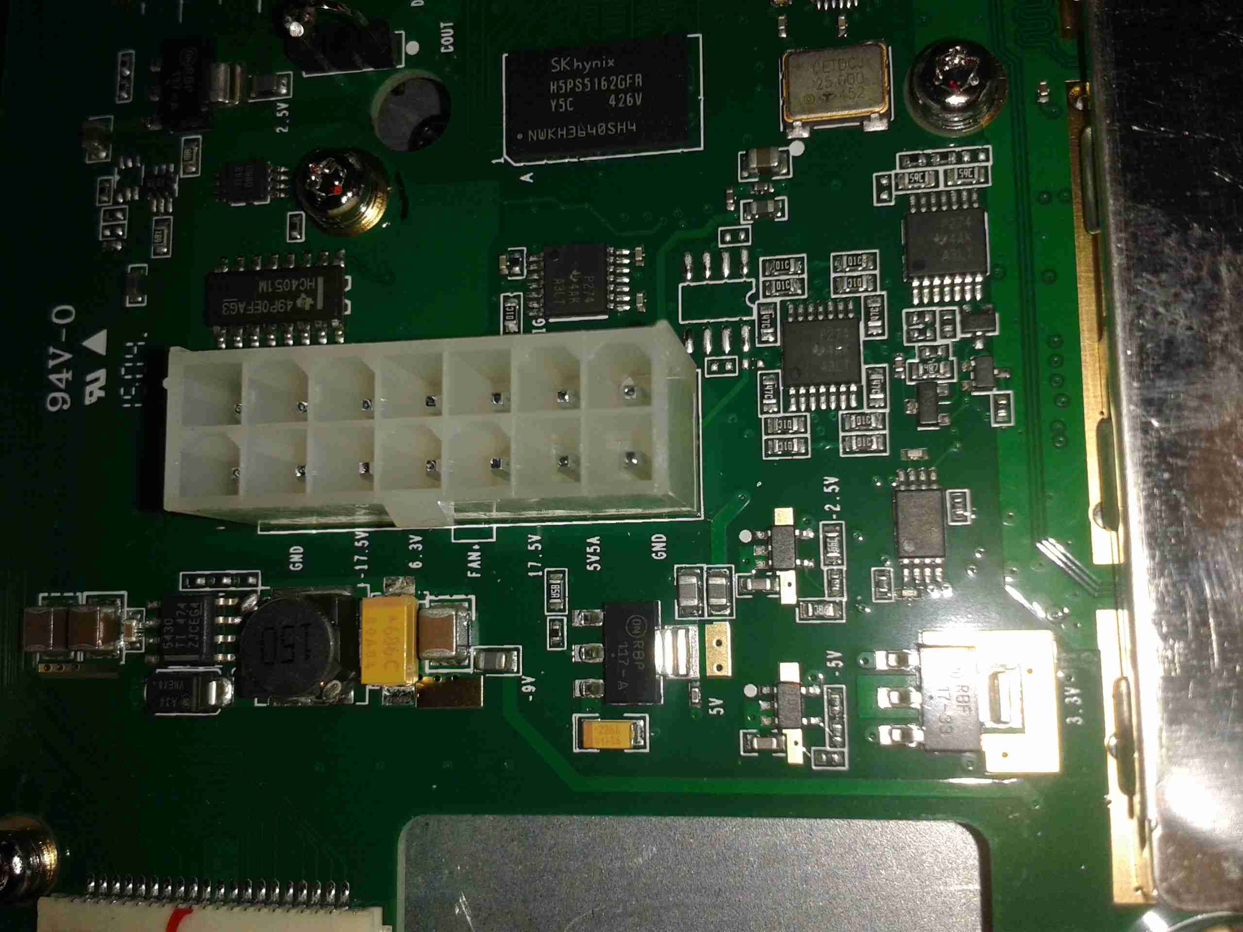
Mainboard Power
Here’s the mainboard power connector, with it’s silkscreen labelling on the pins. (Very useful). As can be seen here, there’s at least 5 regulators, of both switching & linear types here, generating both positive & negative rails.
With every piece of Chinese electronics I obtain, mainly Baofeng radios, they come with a Europlug-type power adaptor, and a universal plug adaptor for the mains.
The charger units aren’t too bad, there’s a fair amount of isolation between the primary & secondary, and even though they’re very simple & cheap, I can’t see any immediate safety problems with them.
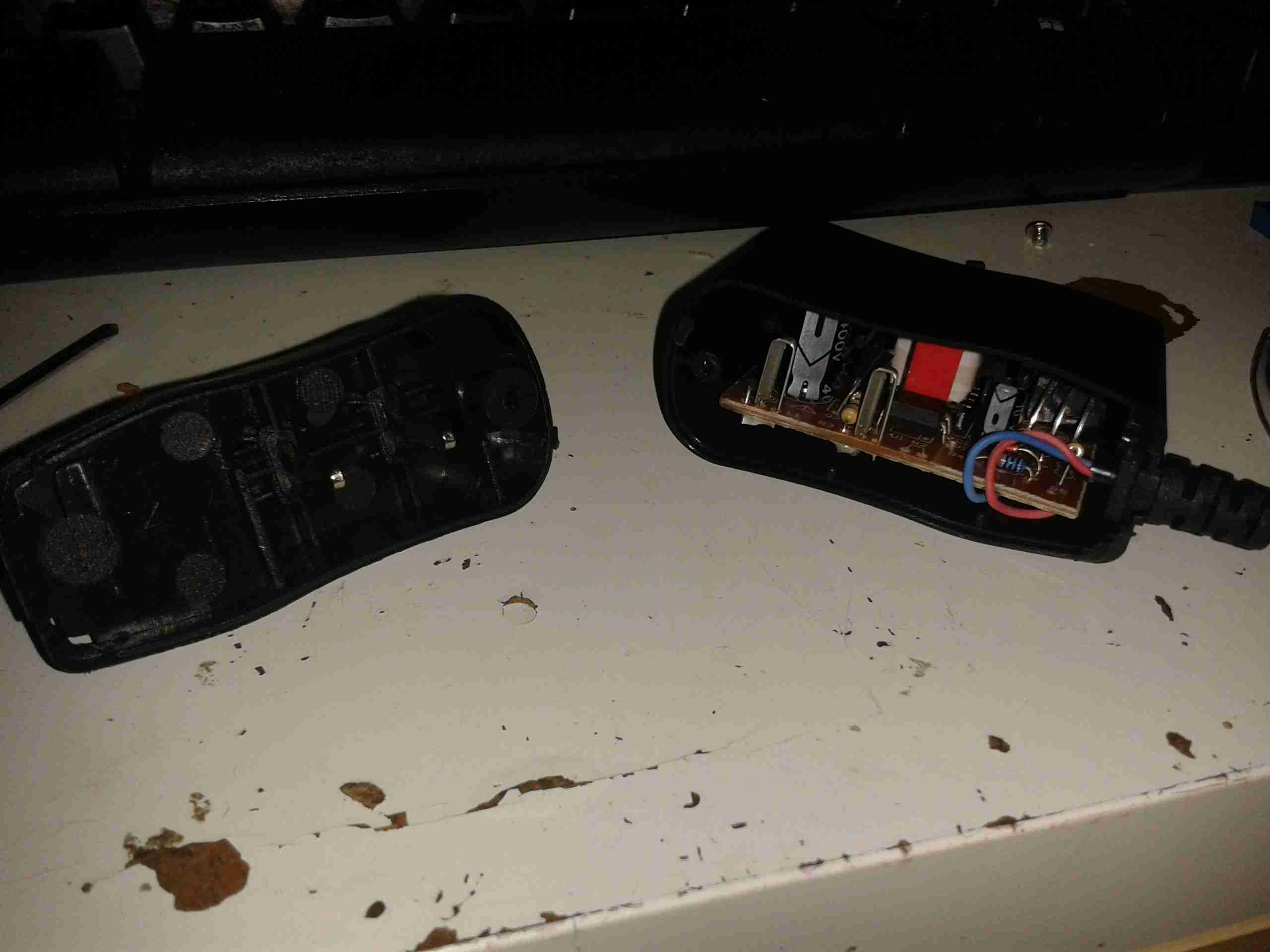
The plug adaptors, however, are a different matter. These things are utterly lethal!
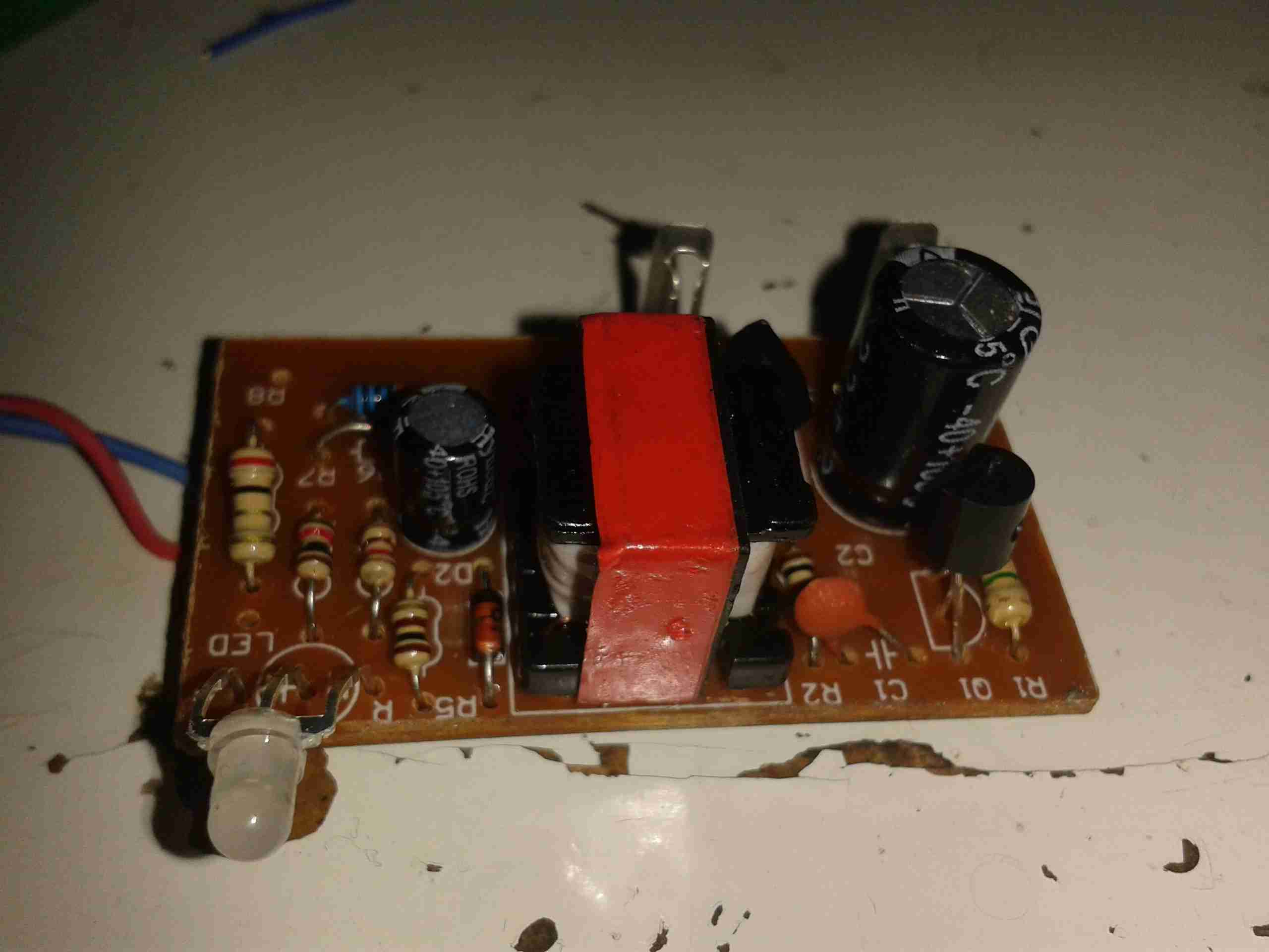
Baofeng PSU
Here’s the inside of the PSU. It’s just a very simple SMPS, giving an output of 10v 500mA. The fuse is actually a fusible resistor.
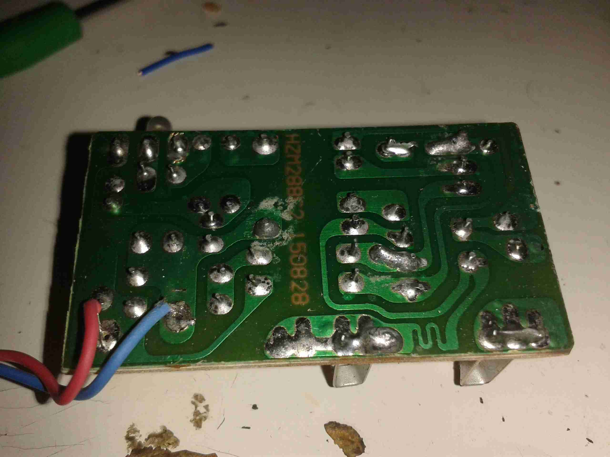
PCB Reverse
Here’s the back of the PCB with the SMPS control IC. I can’t find any English datasheets for this part unfortunately.
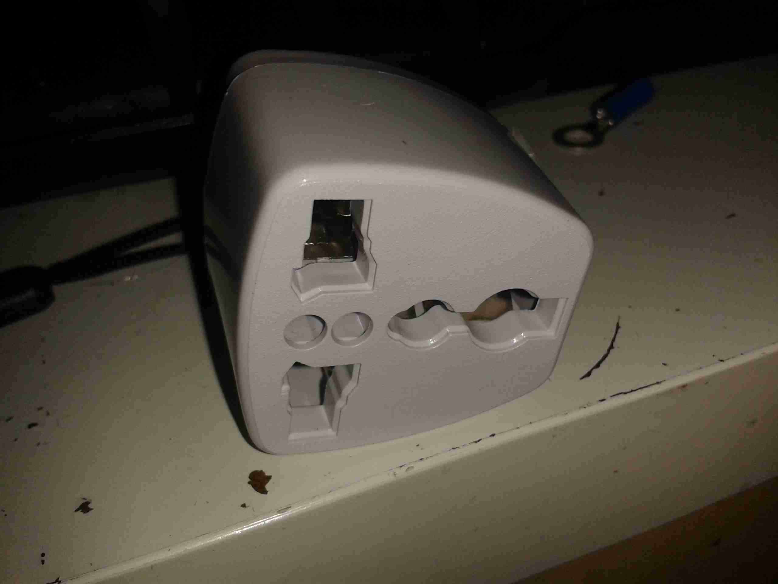
Universal Travel Adaptor
Here’s the dangerous adaptor. There’s no safety shield, so the live parts are exposed.
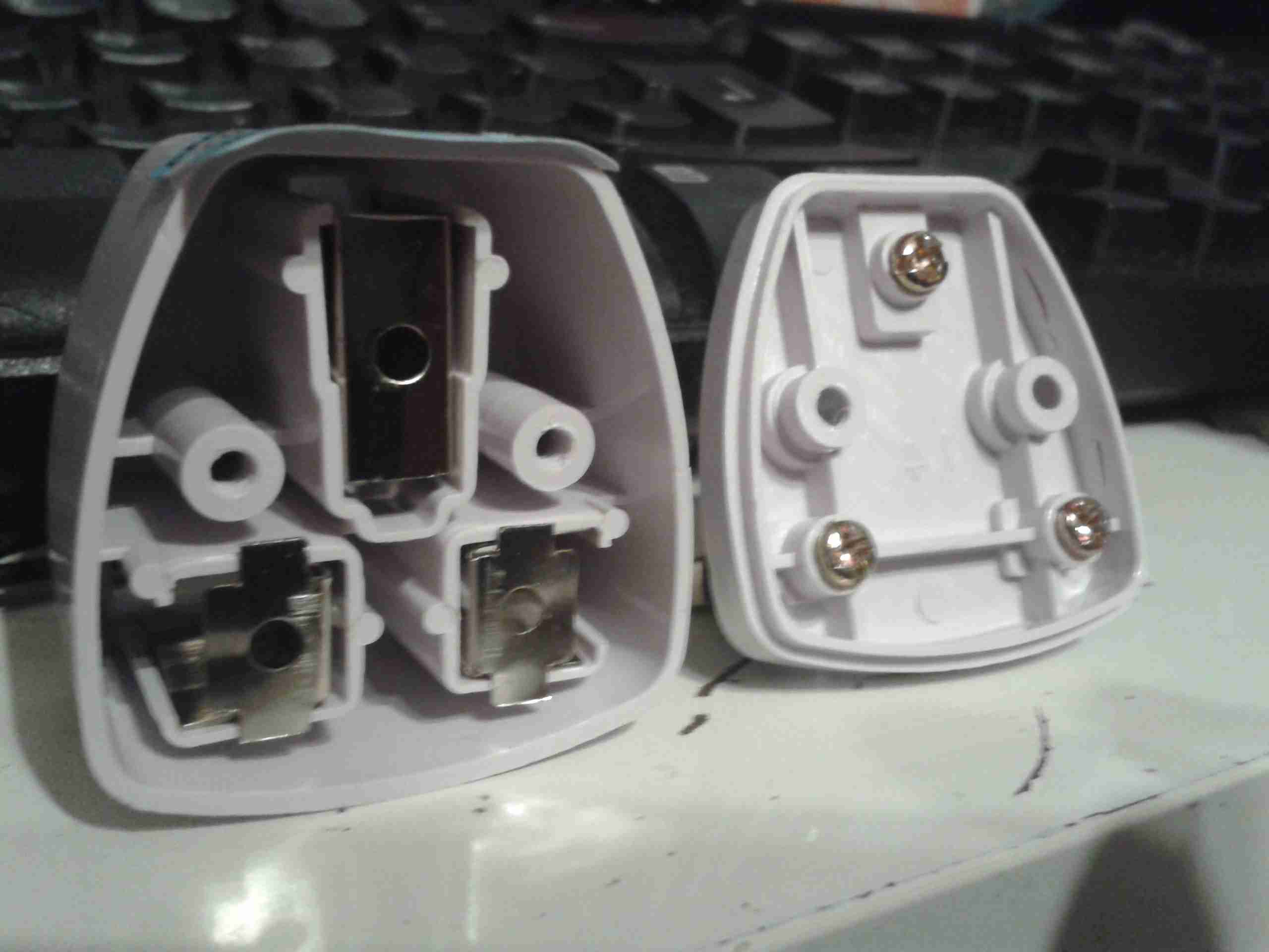
Internals
Here’s the adaptor split apart. The output contacts are on the left, and rely just on pressure to make contact with the brass screws on the mains input pins to provide power.
This is a very poor way to get a connection, a dirty or worn contact here would create a lot of heat if any significant power is pulled through, and could quite possibly result in a fire.
Not surprisingly, I bin these things as soon as I open the box, and charge all my radios with a 12v charging system.
I received this USB supply with a laser module from China that I purchased on eBay. I have heard of these nasty copies of Apple chargers going around, but I’d never received one this bad with a piece of Chinese electronics.
Label
Model No. A1265, so definitely an Apple clone. Apparently capable of +5v DC 1A output. Notice the American NEMA pins. This wouldn’t have been any use to me in the first instance since I am resident in the UK & our mains plugs are significantly different, not to mention significantly safer.
Manufacturer is marked as Flextronics.
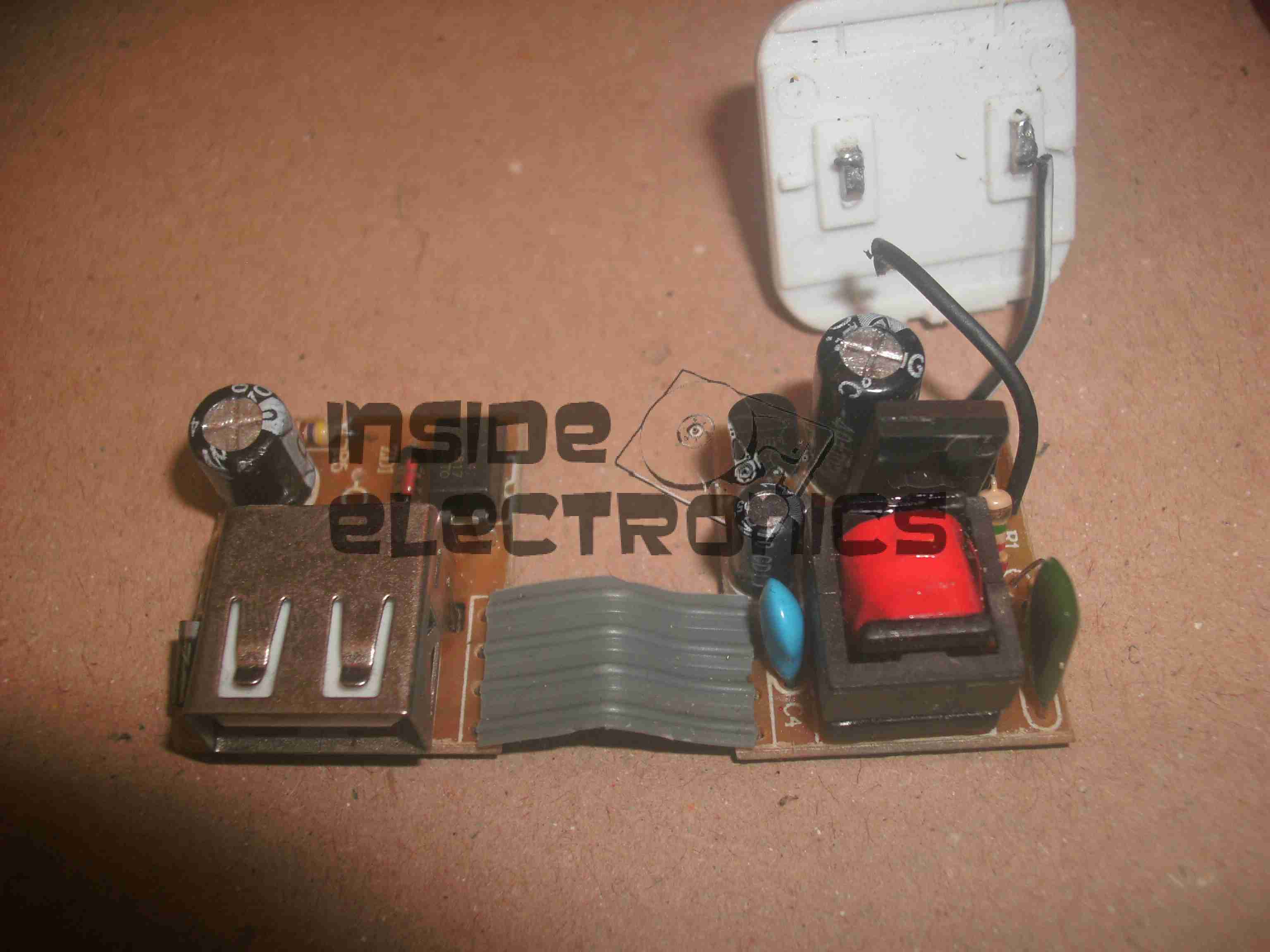
Top Of Boards
Here is the charger disassembled. Inside the case these two boards are folded together, creating an alarmingly small isolation gap between the mains side of the supply & the 5v output. Both the low voltage output & the feedback loop for the supply runs over the 4-core ribbon cable.
The mains wiring from the board is as thin as hair, insulation included, so there is a big possibility of shorts all over the place from this part of the circuit alone.
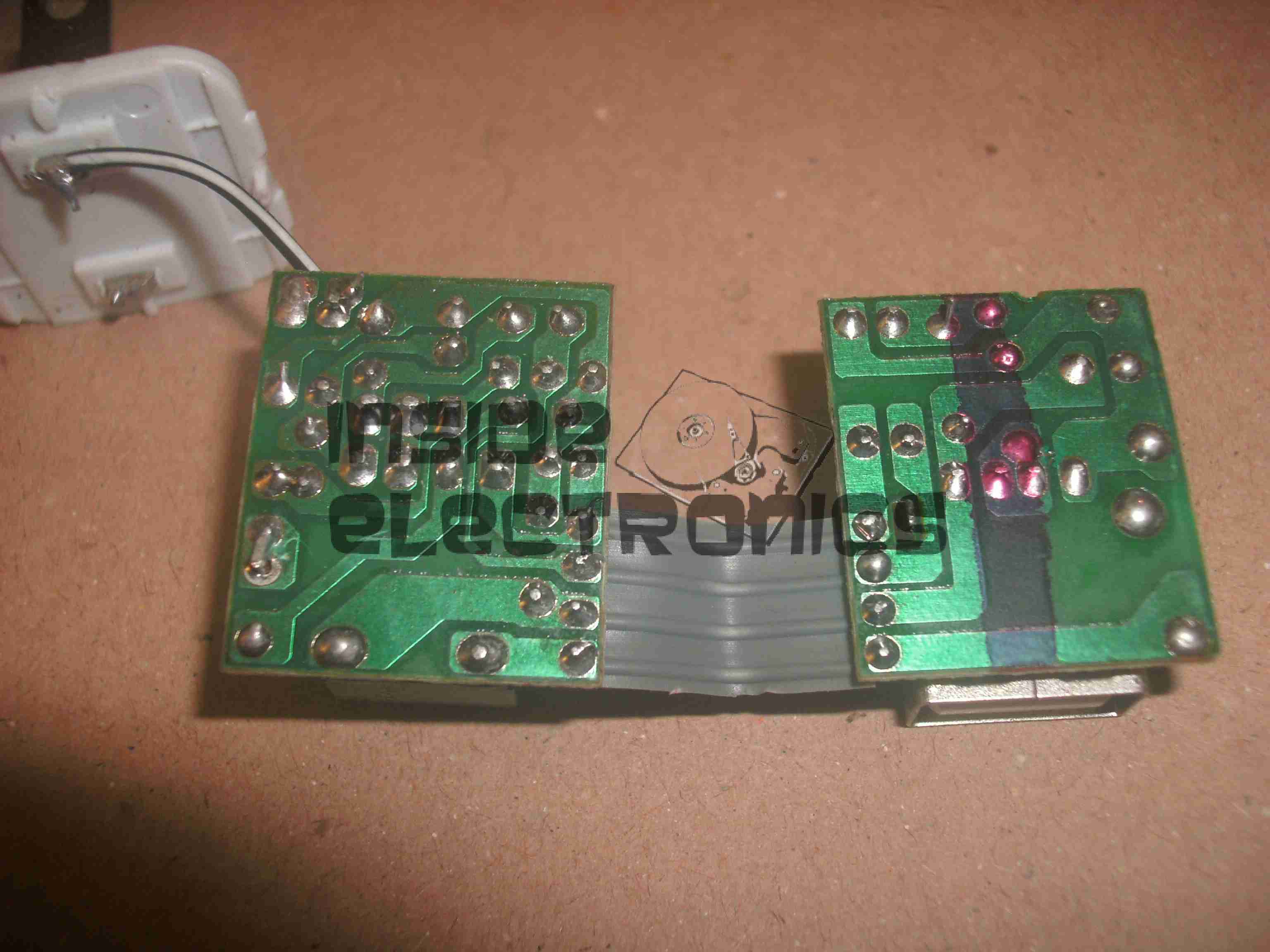
Bottom Of Boards
Bottom of the PCB assemblies. Good luck finding any creepage distance here. There simply isn’t any at all. traces on the +350v DC rail on the mains side of the transformer are no more than 1mm away from the supposedly isolated low voltage side.
Plugging one of these devices into anything is just asking for electrocution.
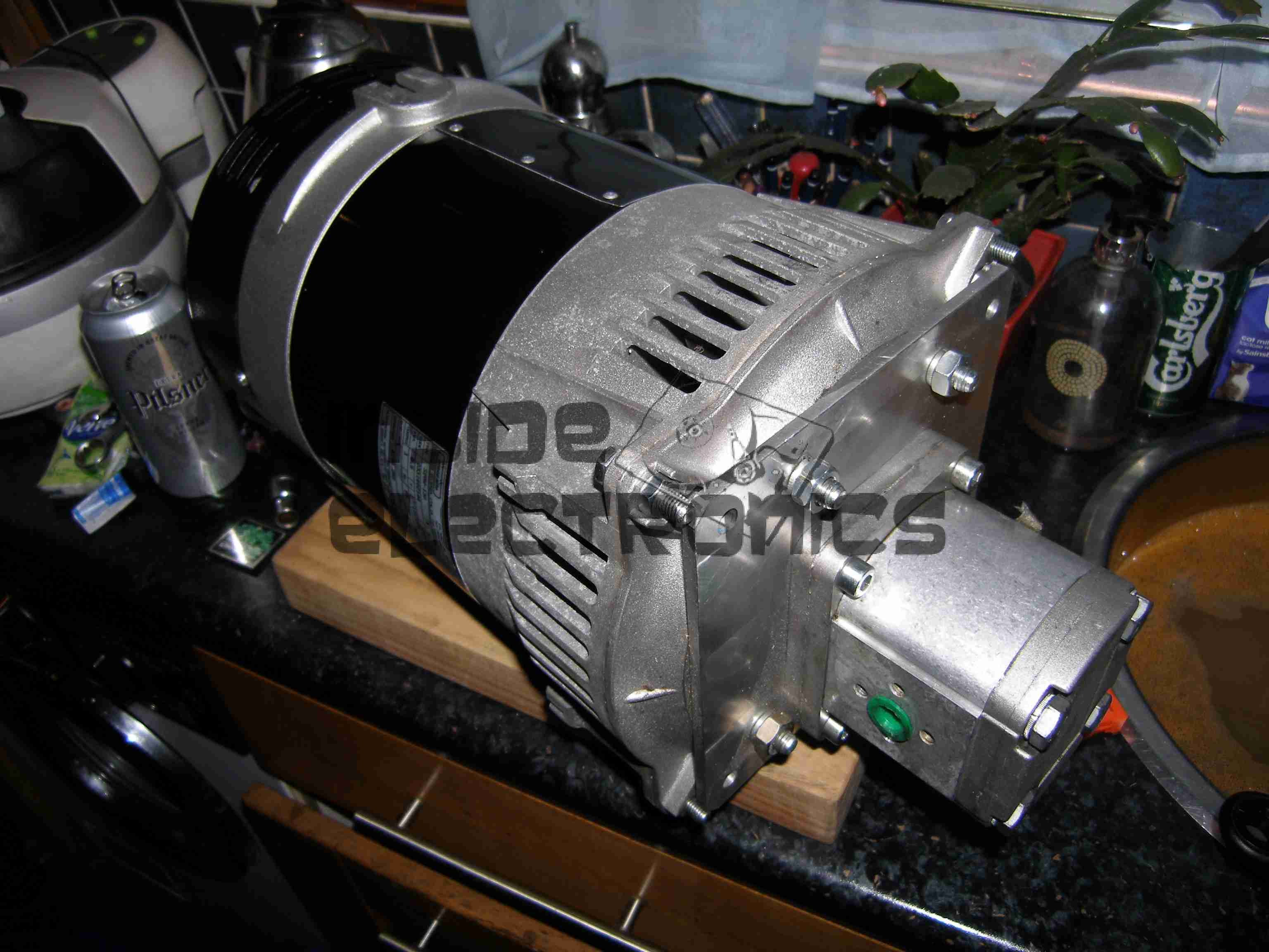
To accompany the previous two posts about hydraulic generators & their components, here is the actual generator unit itself.
Rated at 8.5kVa 230v AC, this will providea mains supply while the narrowboat is away from her home mooring.
This unit will be attached to the side of the hull in the engine room on rubber vibration isolation mounts, behind the main hydraulic oil tank & is driven from the small gear pump attached to the back of the main propulsion hydraulic pump unit.
Operating pressure is 175 bar, 21L/m flow rate to achieve the 3,000RPM rotor speed for 50Hz mains frequency.
Generator Specifications
Tip Jar
If you’ve found my content useful, please consider leaving a donation by clicking the Tip Jar below!
All collected funds go towards new content & the costs of keeping the server online.