Going through eBay recently looking for parts for a couple of CRT-based projects, I came across these DC-DC converters.
Apparently rated from 45-390v DC output at 200mA, these should be ideal for driving some of the electrodes (focus, screen, grid) in a CRT.
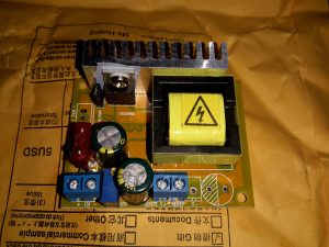
Above is the top of the board, input voltage header on the left, output voltage adjust in the centre & output voltage header on the right.
This module has a mini-automotive fuse, at 10A for input protection.
On the heatsink is mounted the main switching MOSFET, a RU7088R from Ruichips. This FET is fairly heavily rated at 70v 80A, with 6.5mΩ on-resistance.

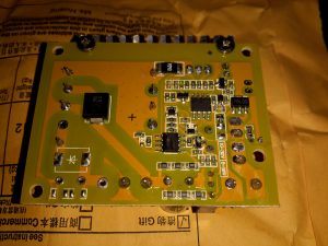
The bottom of the board has the control components, with a pair of ICs. Unfortunately the numbers have been scrubbed off, so no identification here. The output from the transformer is rectified with a single large SMD diode on the left side of the board.
There’s also plenty of isolation gap between the HV output trace & the low voltage logic side of the circuit, the two being bridged only by a resistive divider for output voltage measurement.

I’m using 8 of theese cheap ZVS modules to deliver ~325 VDC to an EG8010 -based Pure Sine Inverter.
For long term stability I changed the chinabrand capacitors to 15uF Panasonic ED -A ( High Frequency + 10000 hours @ 105 C ).
You can of cause wait for the fugganakki caps to fail, but in my case I allready had the others in stock.
The input capacitors are a bit easier. I took some nicely oversized Nichicon 50V/470uF which will last many years @ normal temperatures.
The low voltage input plus on/off control jumper on the boards can be directly connected in parallel.
The high-voltage output CAN’T be directly connected but needs a diode on each positive out.
The outout Ground terminals can of cause be connected directly.
All the ZVS modules are trimmed to same output voltage before they are hooked up.
The inverter has 2 input capacitors each 400V/100uF => 200uF total.
This should just be bigger than sum of 8 * 15uF on the ZVS’s to ensure the diodes see’s lower ripple on the output.
I’m not drawing more than 200W from the inverter, so everything runs relative cool. 🙂