Posted on Leave a comment

Camping Support Trolley – Some Build Progress

Since I do festivals every year, along with a couple of other camping trips if the weather is good enough, I’ve been taking equipment with me for years in flight cases to make things more comfortable. Things like a large battery to power lights & device charging, an old Eberspacher diesel heater for the times when the weather isn’t great, and an inverter to run the pumps built into airbeds.

Red Diesel / Heating Oil is my fuel of choice for camping purposes, as it’s about the safest fuel around, unlike Butane/LPG it is not explosive, will not burn very readily unless it’s atomized properly & it’s very cheap. Paraffin is an alternative fuel, but it’s expensive in the UK, at about £12 per 5L.
The Hexamine-based tablet fuels the UK festivals promote is nasty stuff, and the resulting combustion products are nastier still. (Things like Hydrogen Cyanide, Formaldehyde, Ammonia, NOX). They also leave a sticky black grok on every cooking pot that’s damn near impossible to remove. Meths / Trangia stoves are perfectly usable, but the flame is totally invisible, and the flammability of alcohol has always made me nervous when you’ve got a small pot of the stuff boiling while it’s in operation in the middle of a campsite filled with sloshed festival goers. A single well-placed kick could start a massive fire.

Previous System
Previous System

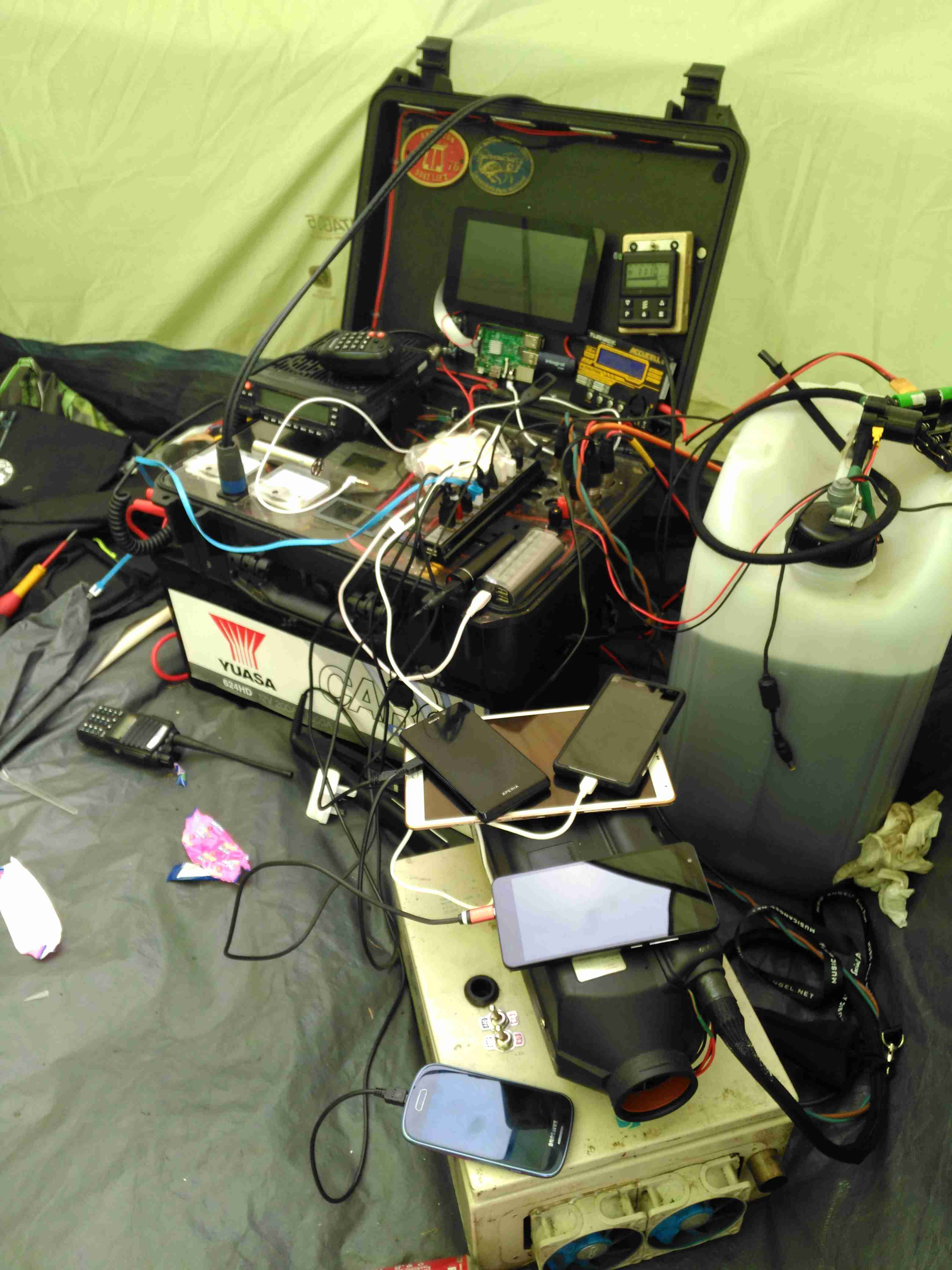
Over the years the gear has evolved and grown in size, so I decided building everything into one unit on wheels would be the best way forward. I’ve been working on this for some time, so it’s time to get some of the details on the blog! Above you can see the system used for last year’s camping, the heater is separate, with a 25L drum of heating oil, the battery is underneath the flight case containing all the power components, and it’s currently charging All The Things.

Overview
Overview

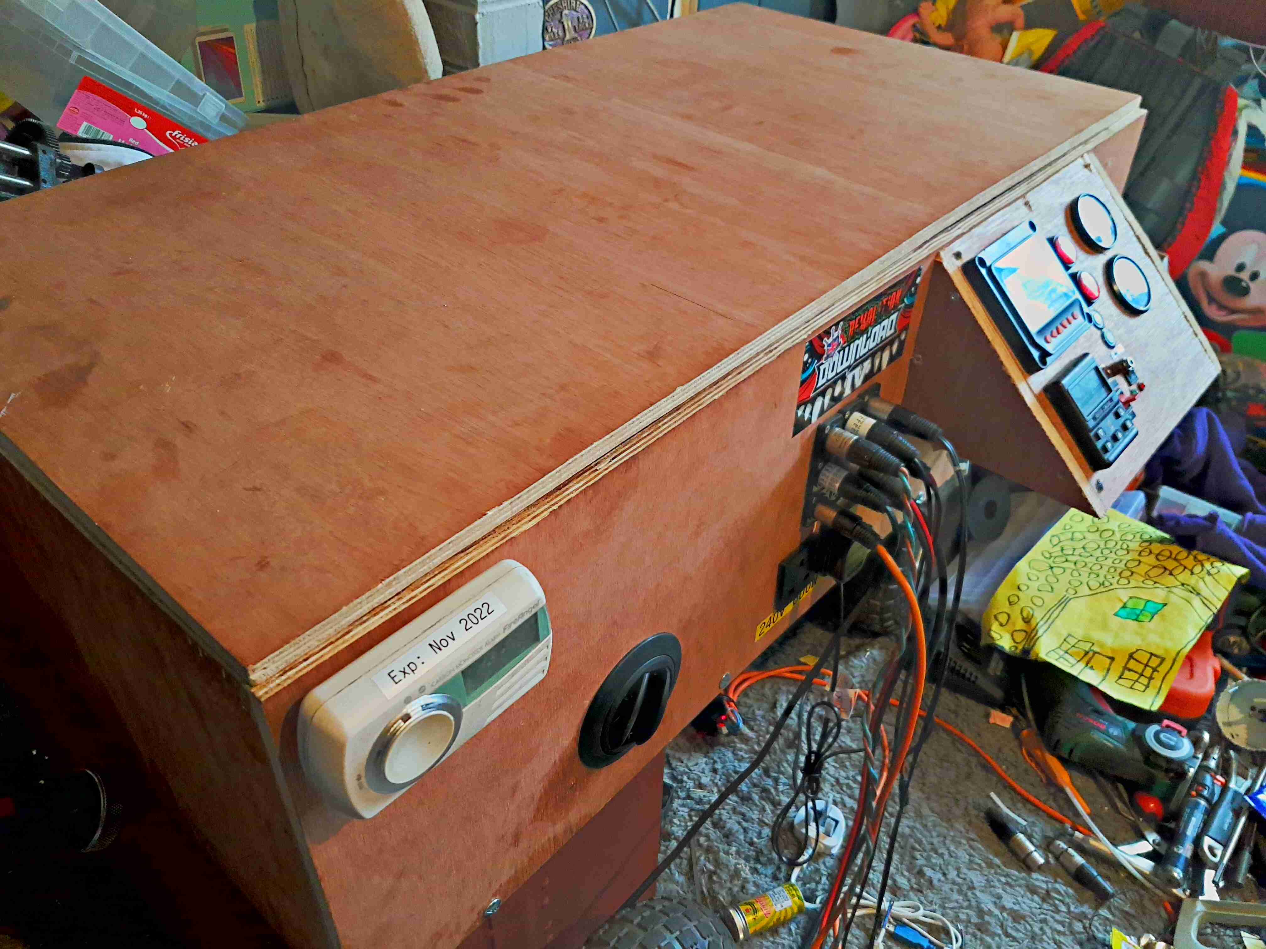
Above is the new unit almost finished, the bottom frame is a standard eBay-grade 4-wheel trolley with a few modifications of my own, with a new top box built from 12mm hardwood marine plywood. This top is secured in place with coach bolts through the 25mm angle iron of the trolley base. The essential carbon monoxide detector is fitted at the corner.

Internal View
Internal View

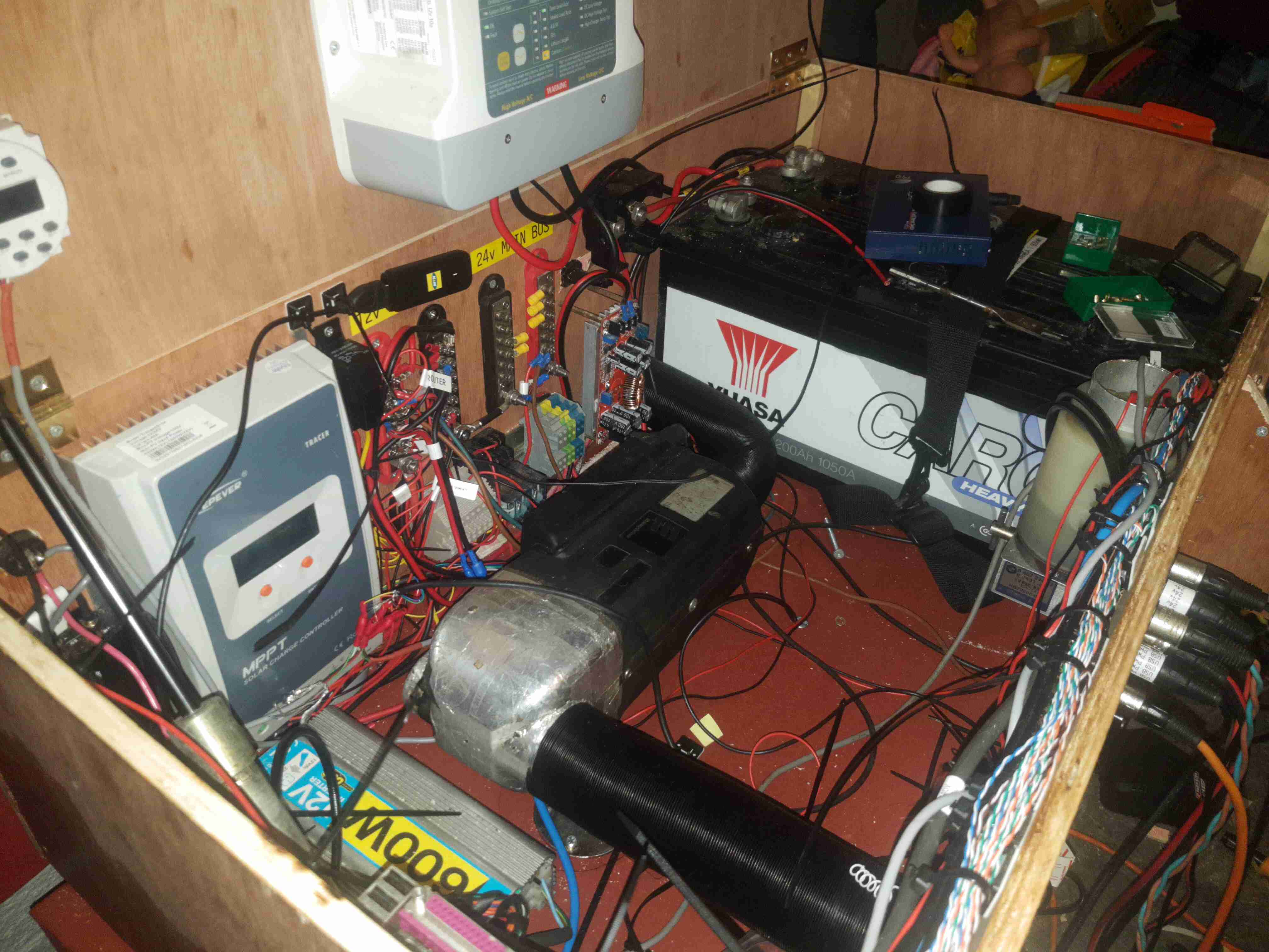
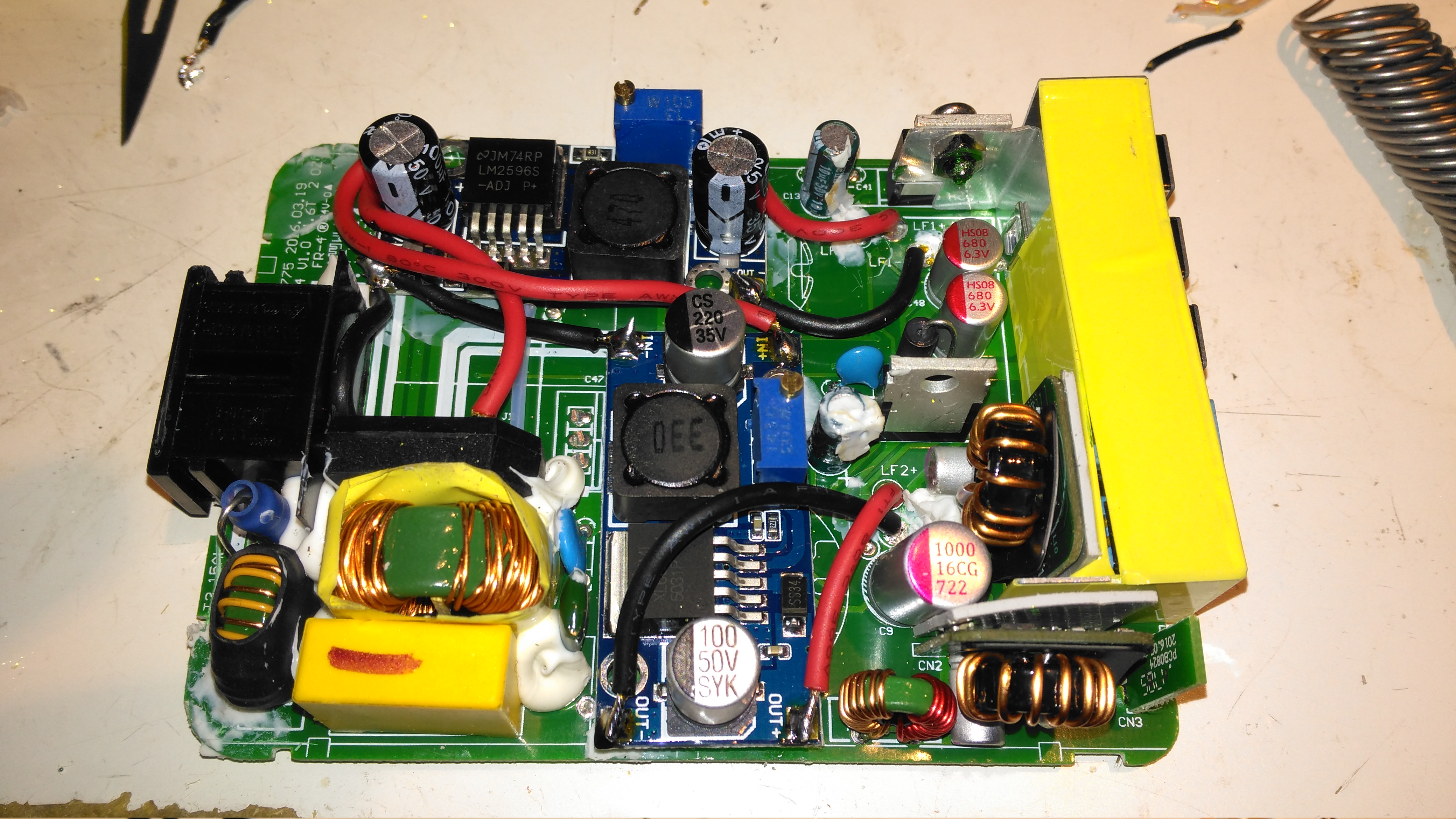
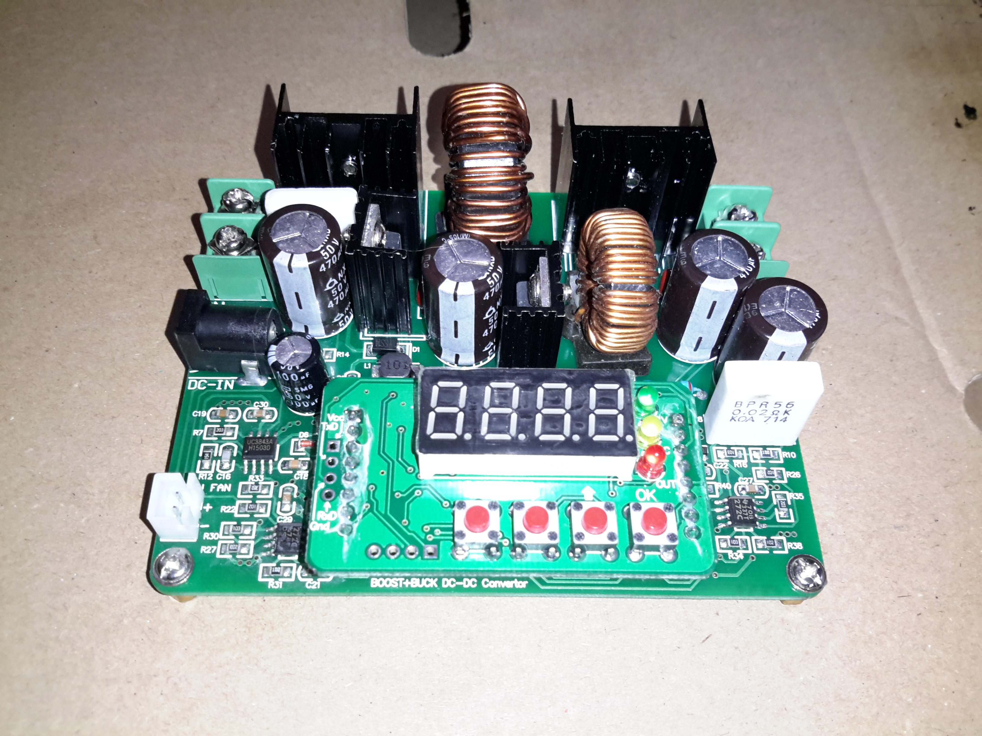
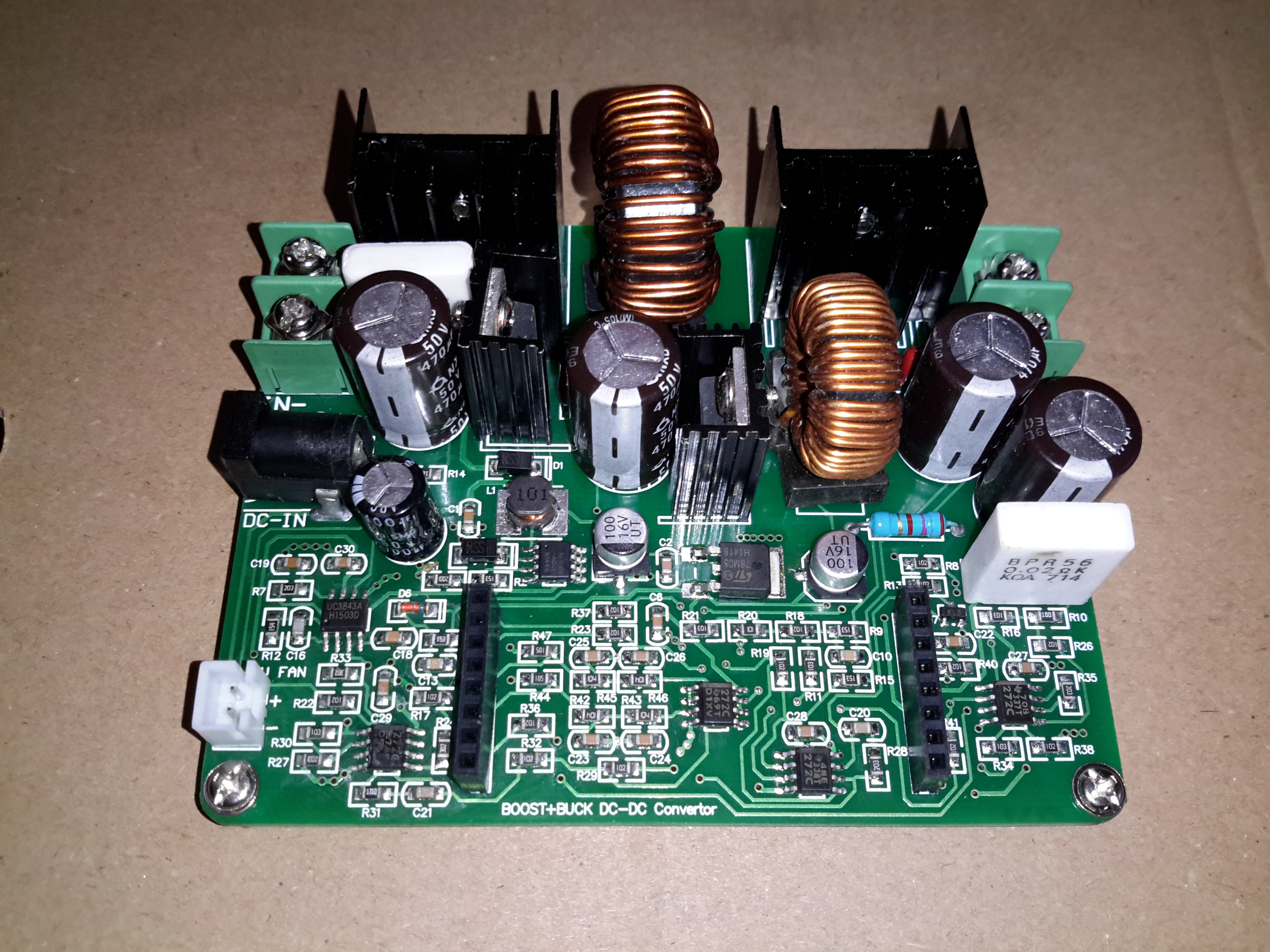
The inside gets a bit busy with everything crammed in. The large Yuasa 200Ah lead-acid battery is at the far end, with it’s isolation switch. Right in the middle is the Eberspacher heater with it’s hot air ducting. I’ve fitted my usual 12/24v dual voltage system here, with the 24v rail generated from a large 1200W DC-DC converter.

Heater Vent
Heater Vent

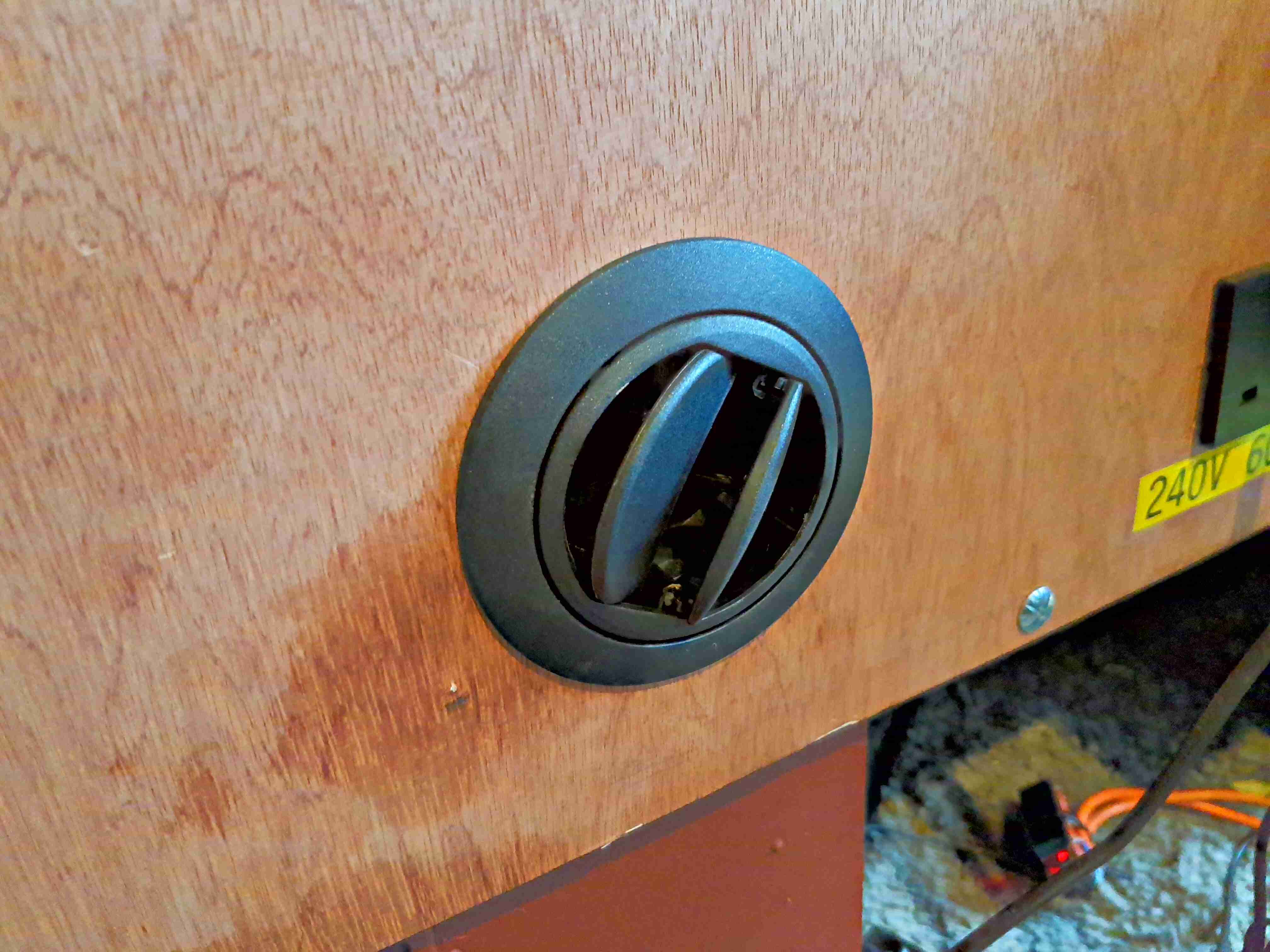
The hot air duct for the heater is fed out through a standard vent in the front. Very handy for drying out after a wet day.

Main Bus Bars & Solar Controller

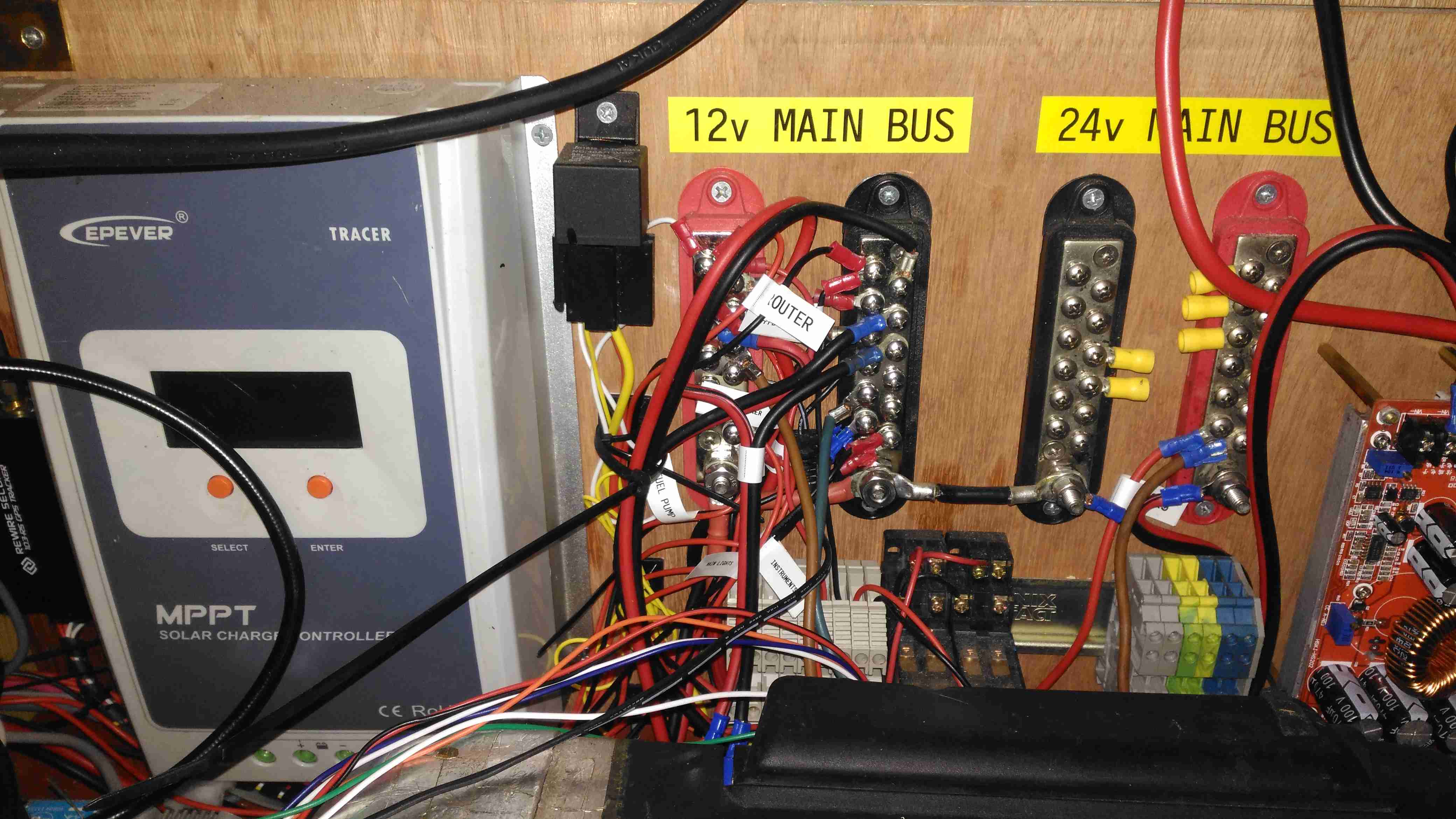
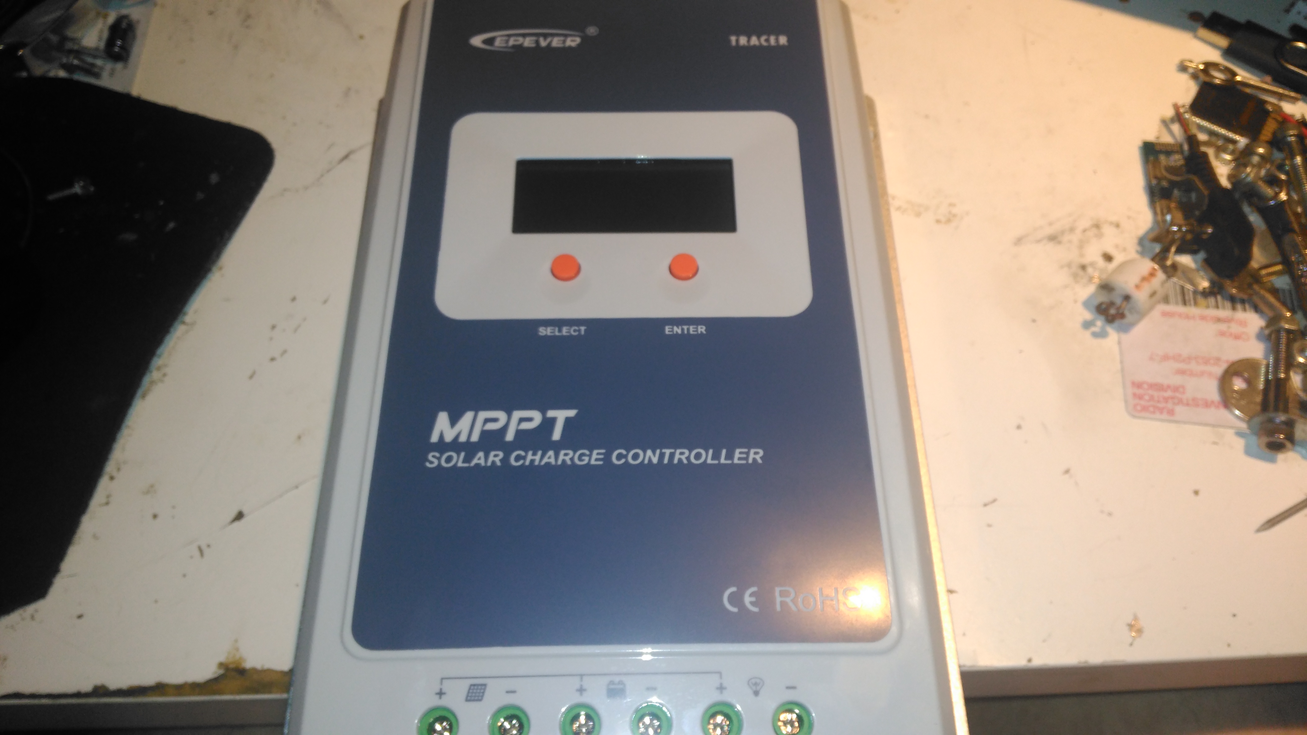
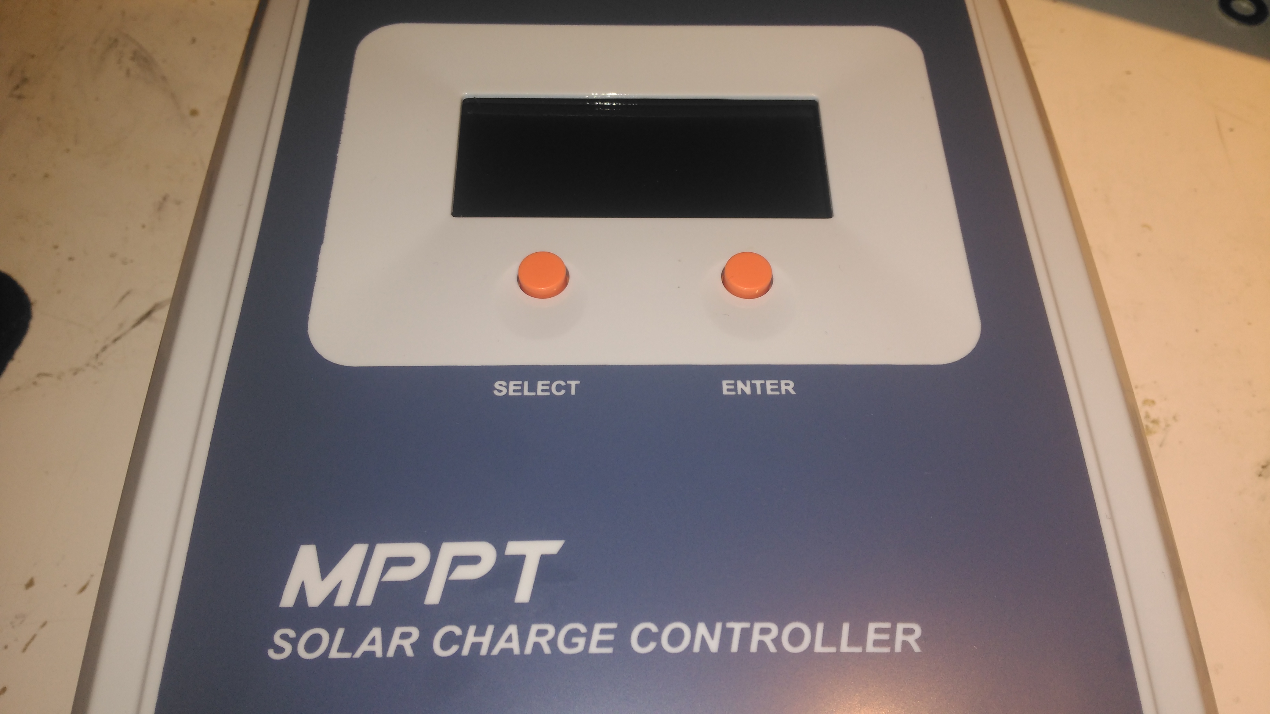
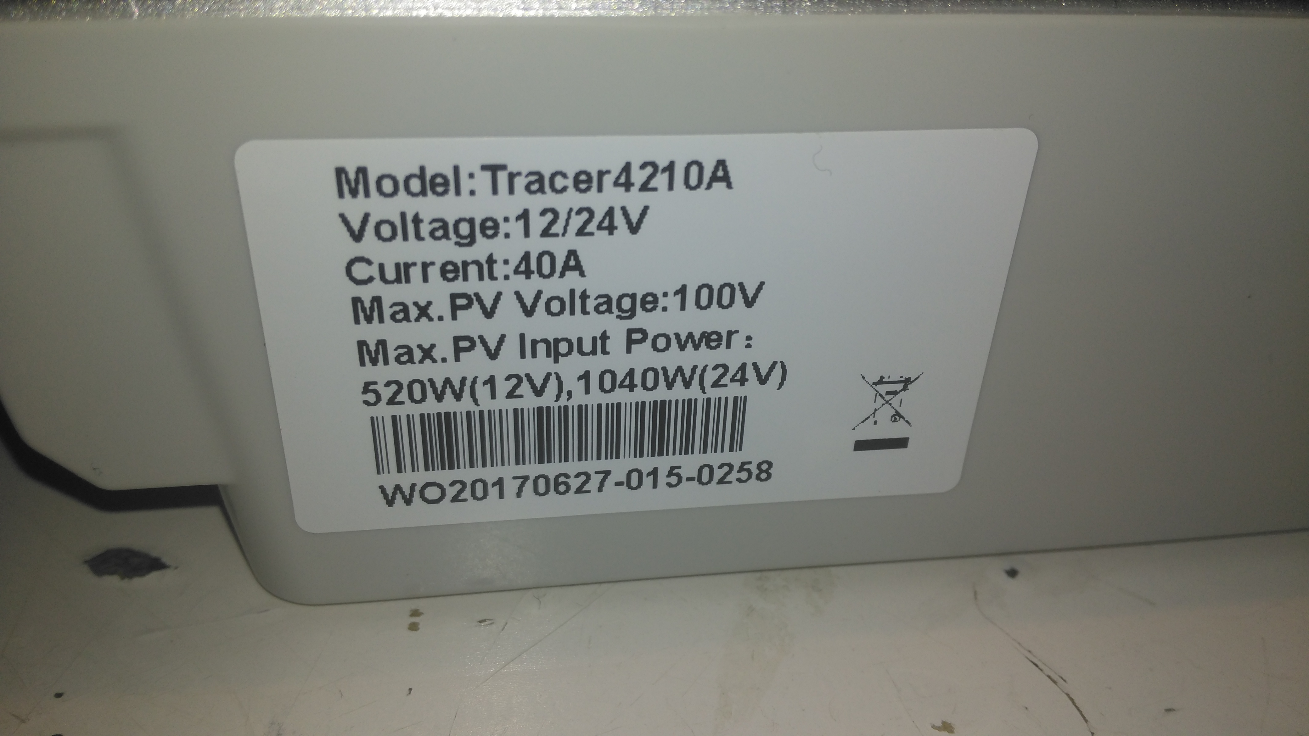
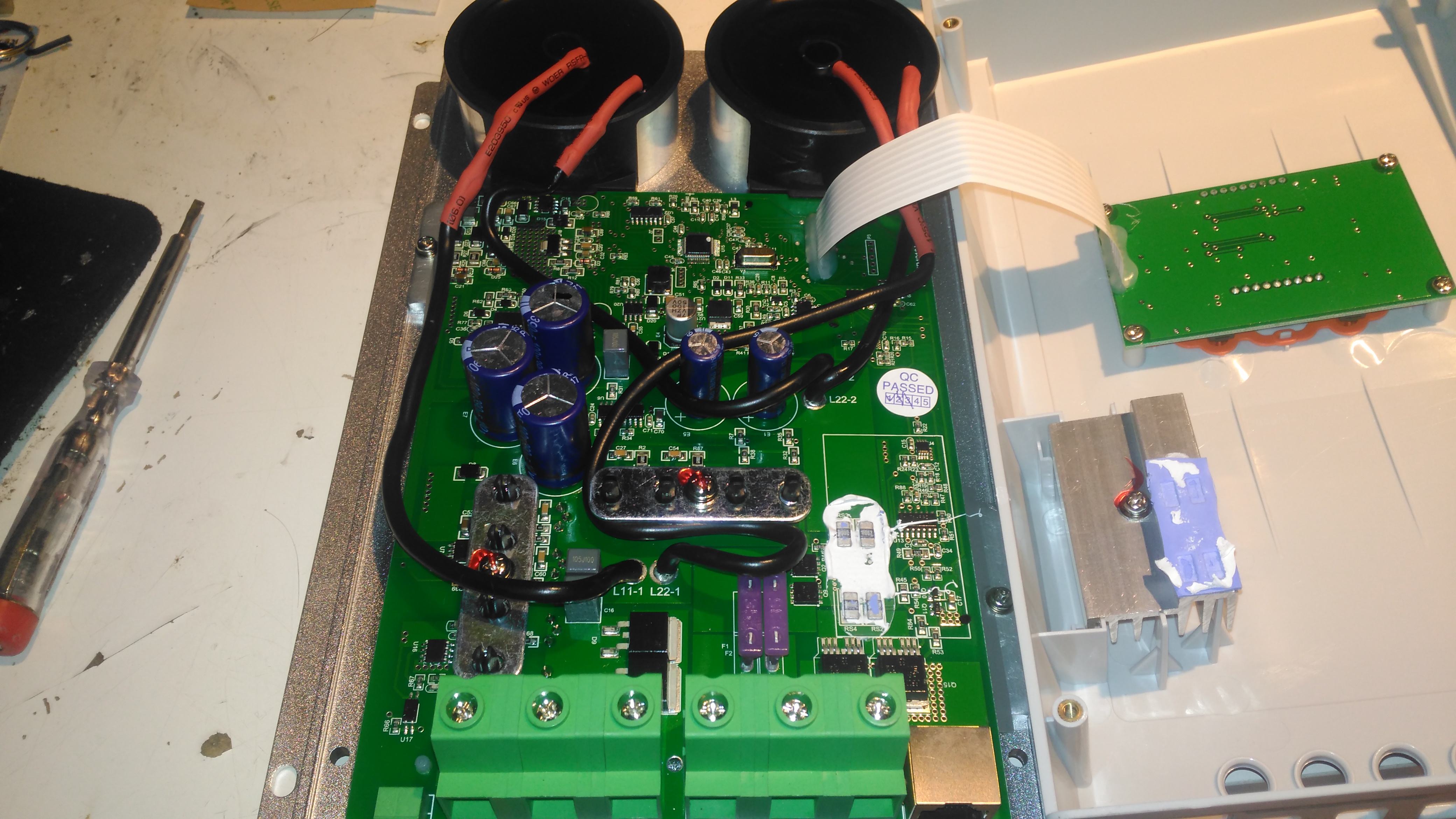
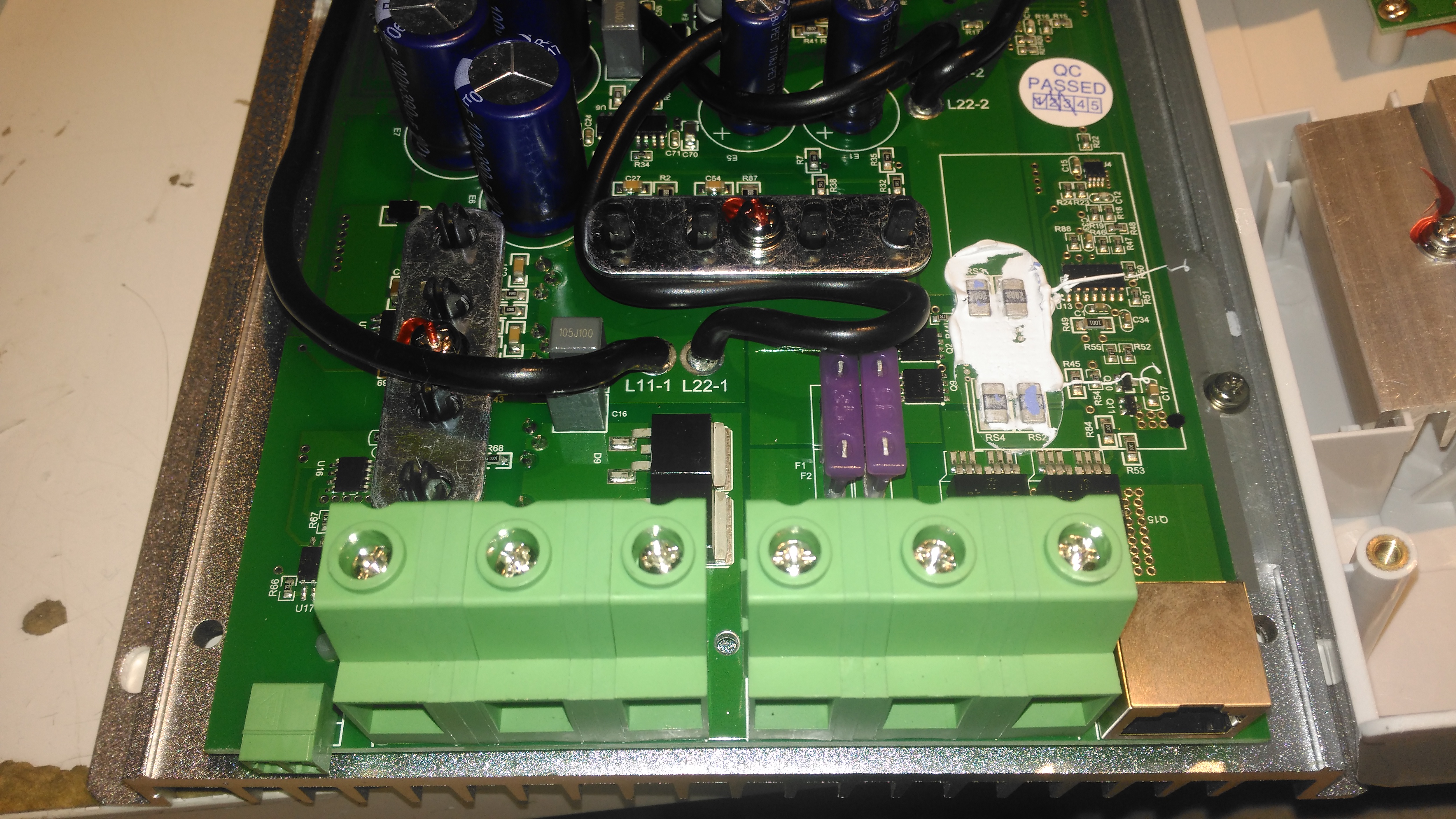
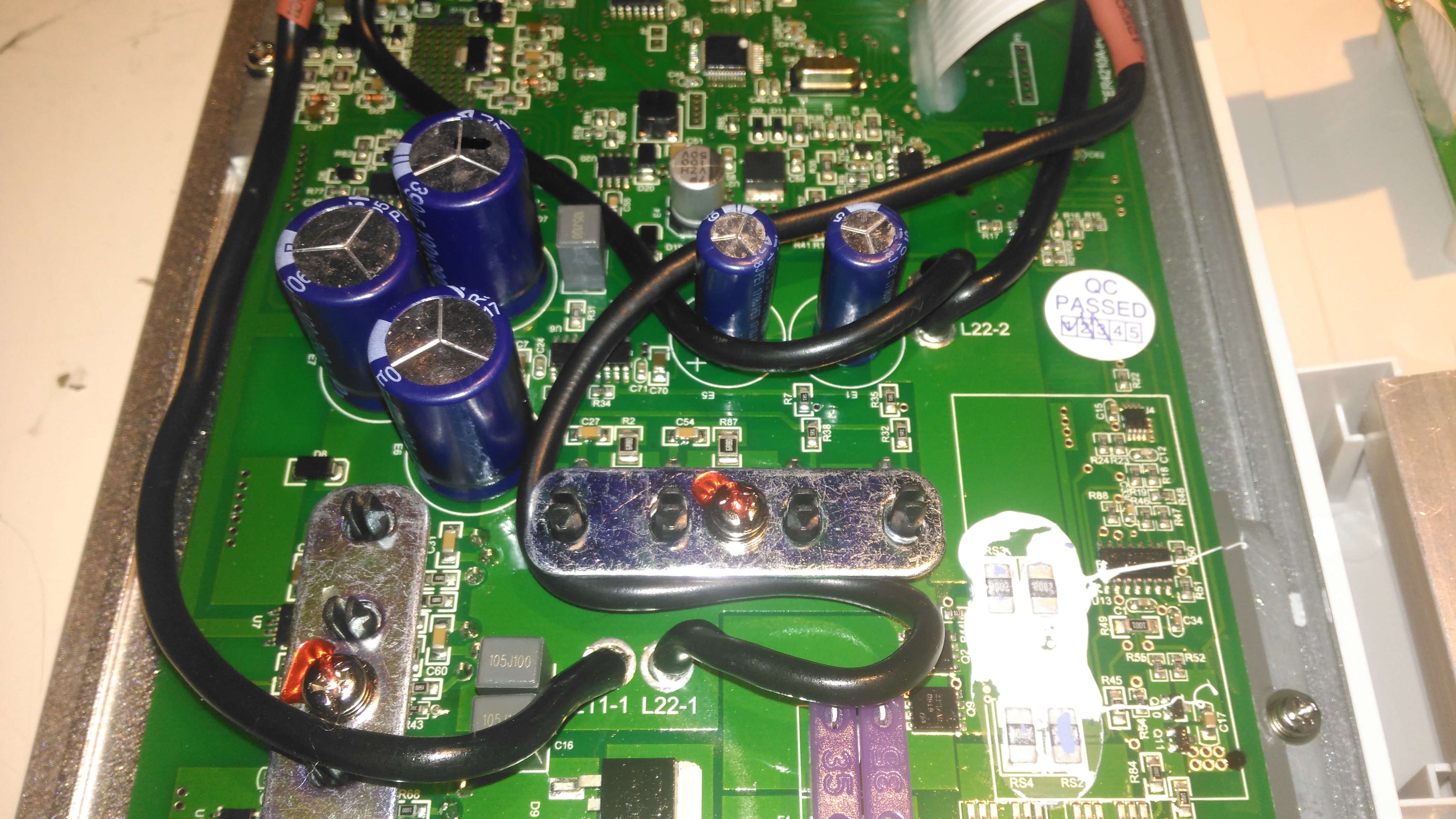
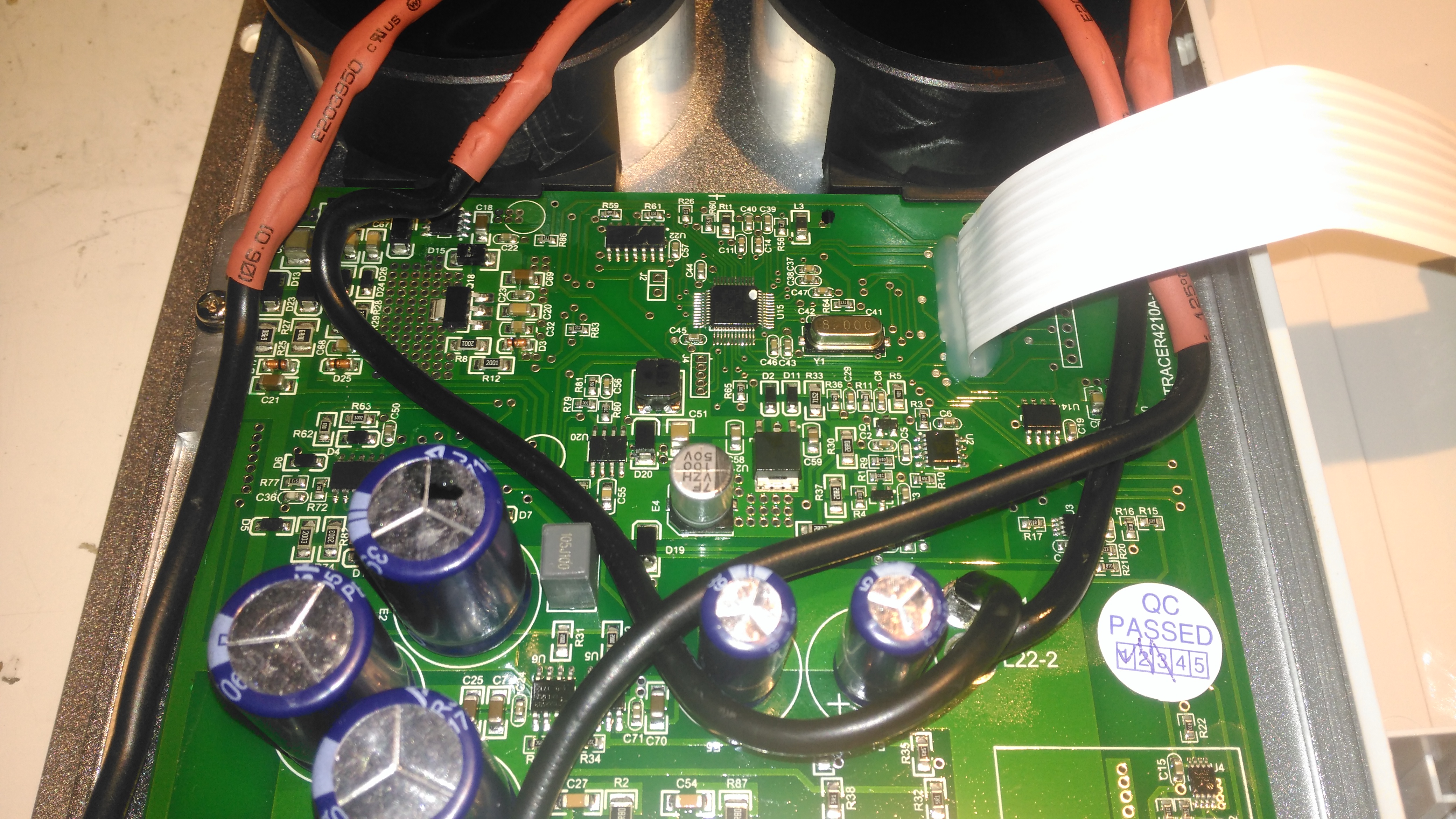
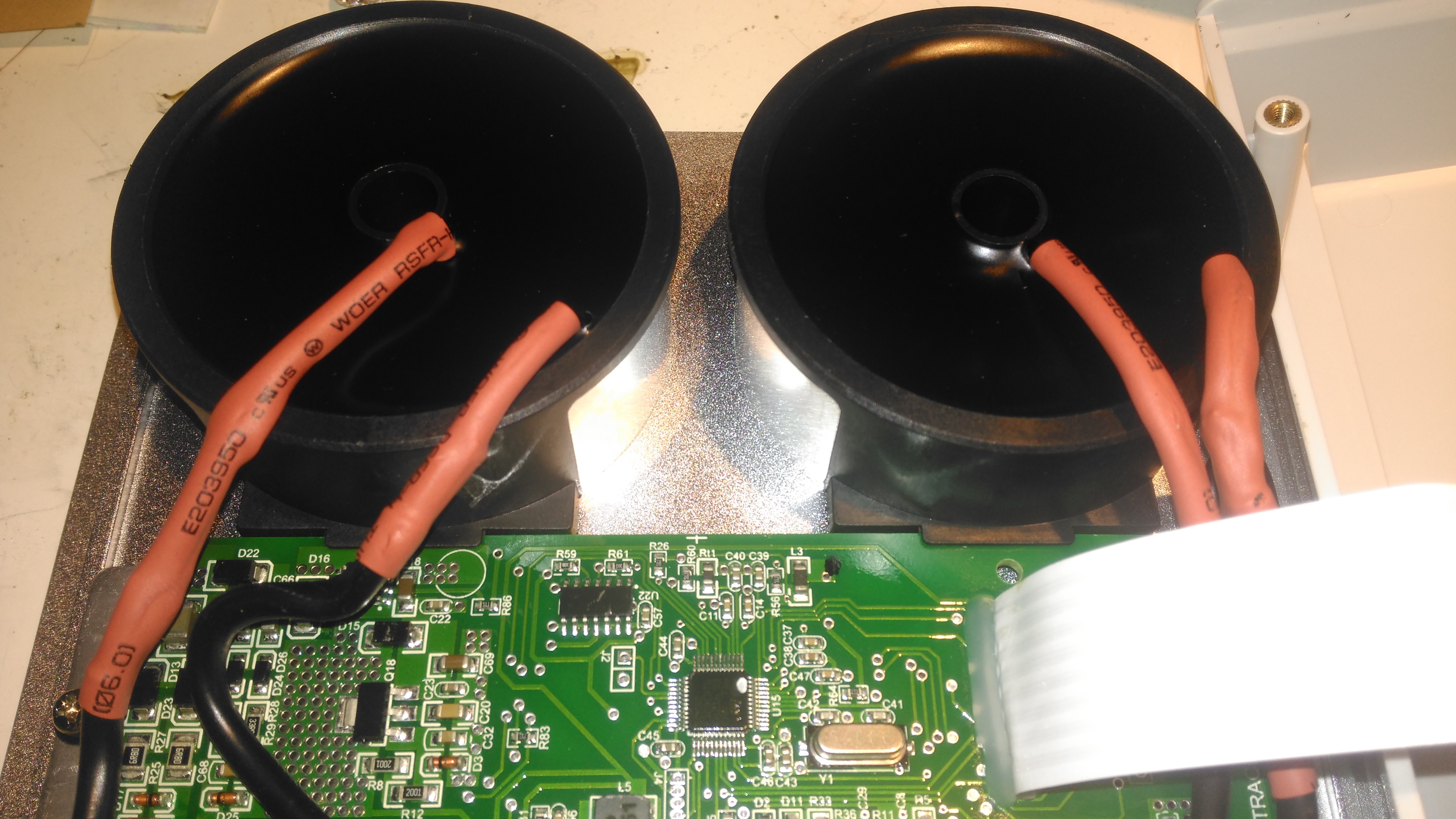
Here’s a closeup of the distribution bus bars, with both negative rails tied together in the centre to keep the positives as far away from each other as possible, to reduce the possibility of a short circuit between the two when working on the wiring. The EpEver Tracer 4210A MPPT Solar Charge Controller is on the left, tucked into the corner. This controller implements the main circuit protection for the battery, having a 40A limit. Individual circuits are separately fused where required. Solar input on this unit is going to be initially provided by a pair of 100W flexible panels in series for a 48v solar bus, the flexible panels are essential here as most of the festivals I attend do not allow glass of any kind onsite, not to mention the weight of rigid panels is a pain.

DC Output Sockets
DC Output Sockets

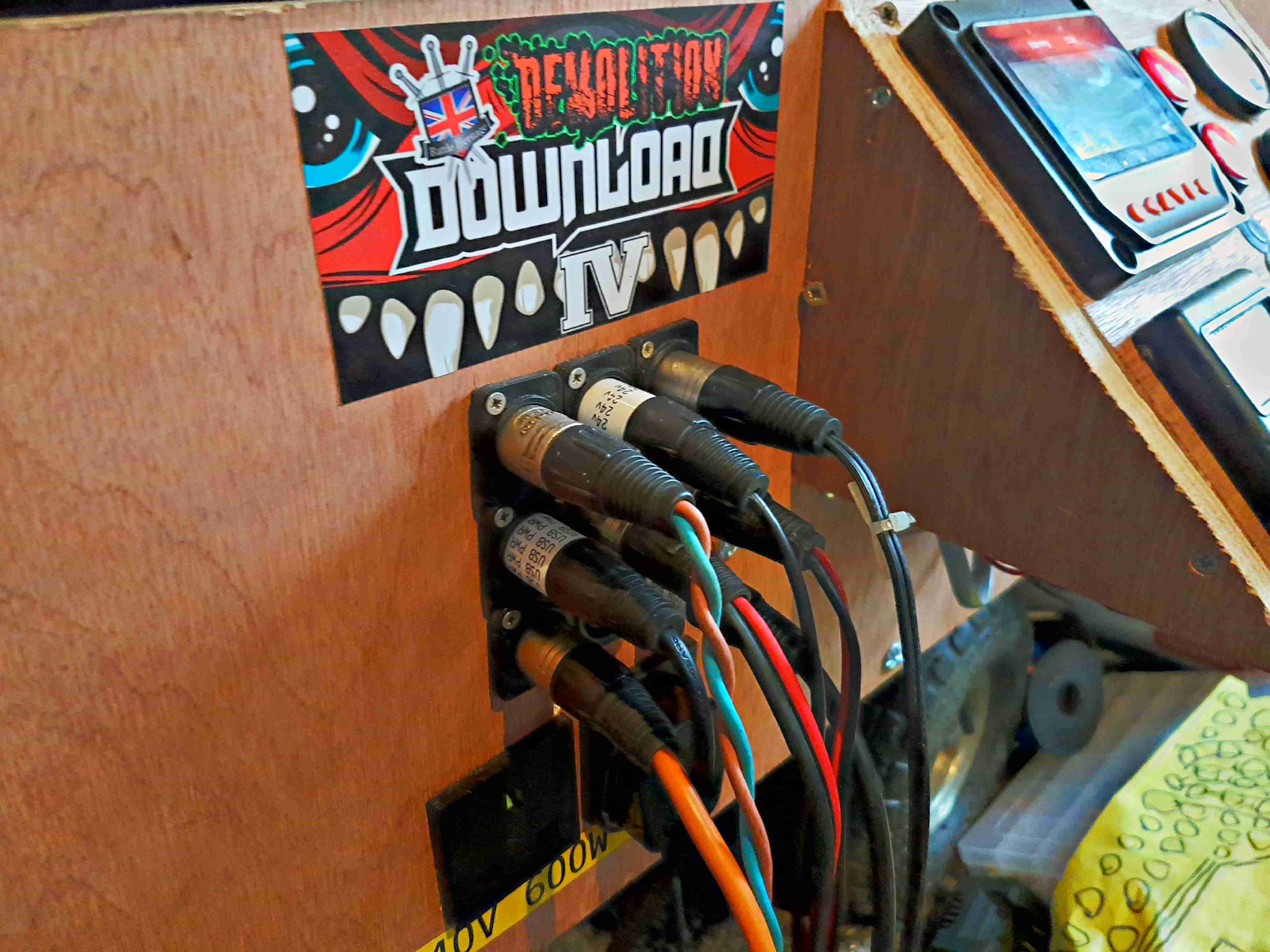
I’ve stuck with the 3-pin XLR plugs for power in this design, giving both the 12v rail, 24v rail & ground.

Inverter Outputs
Inverter Outputs

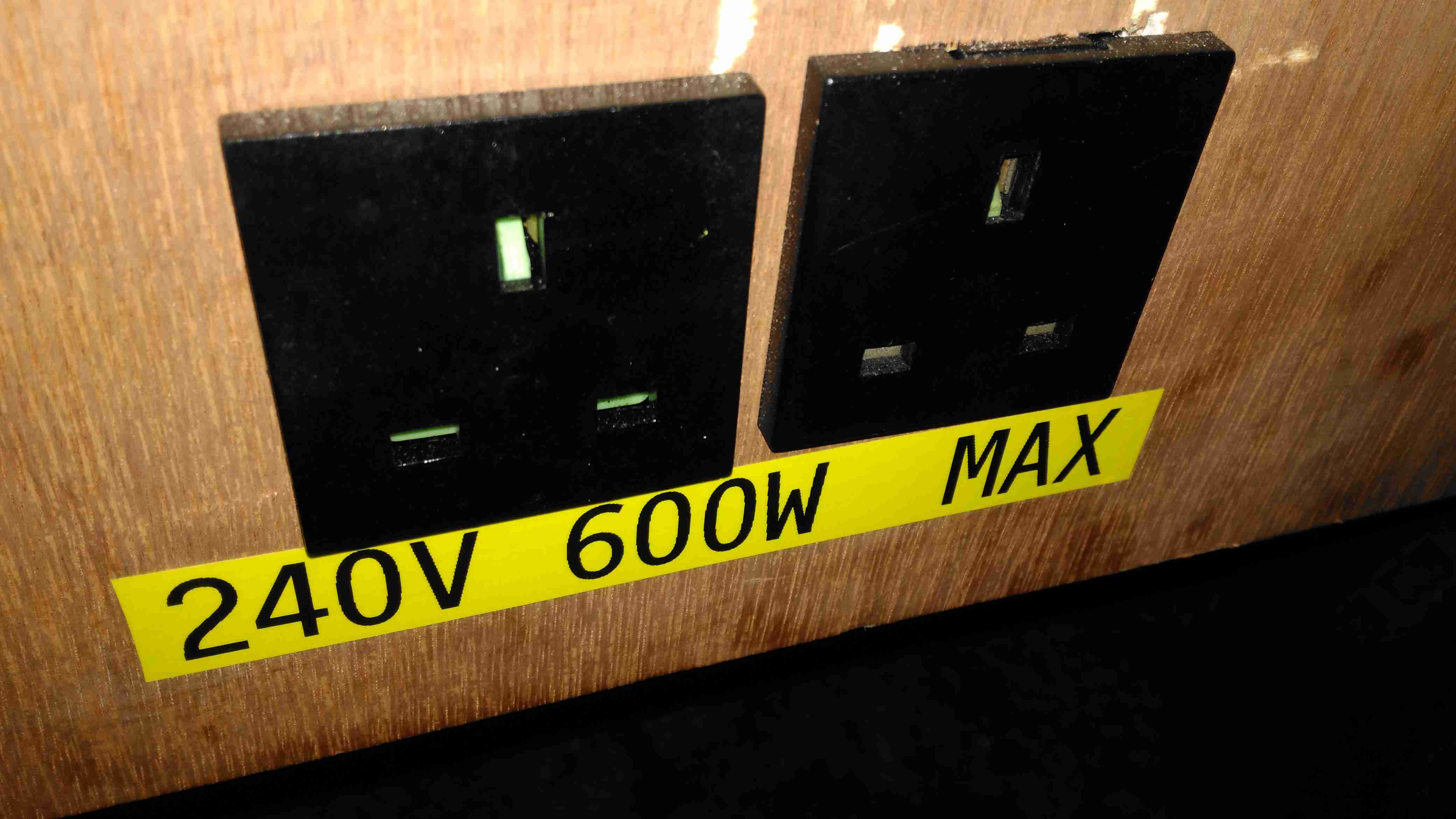
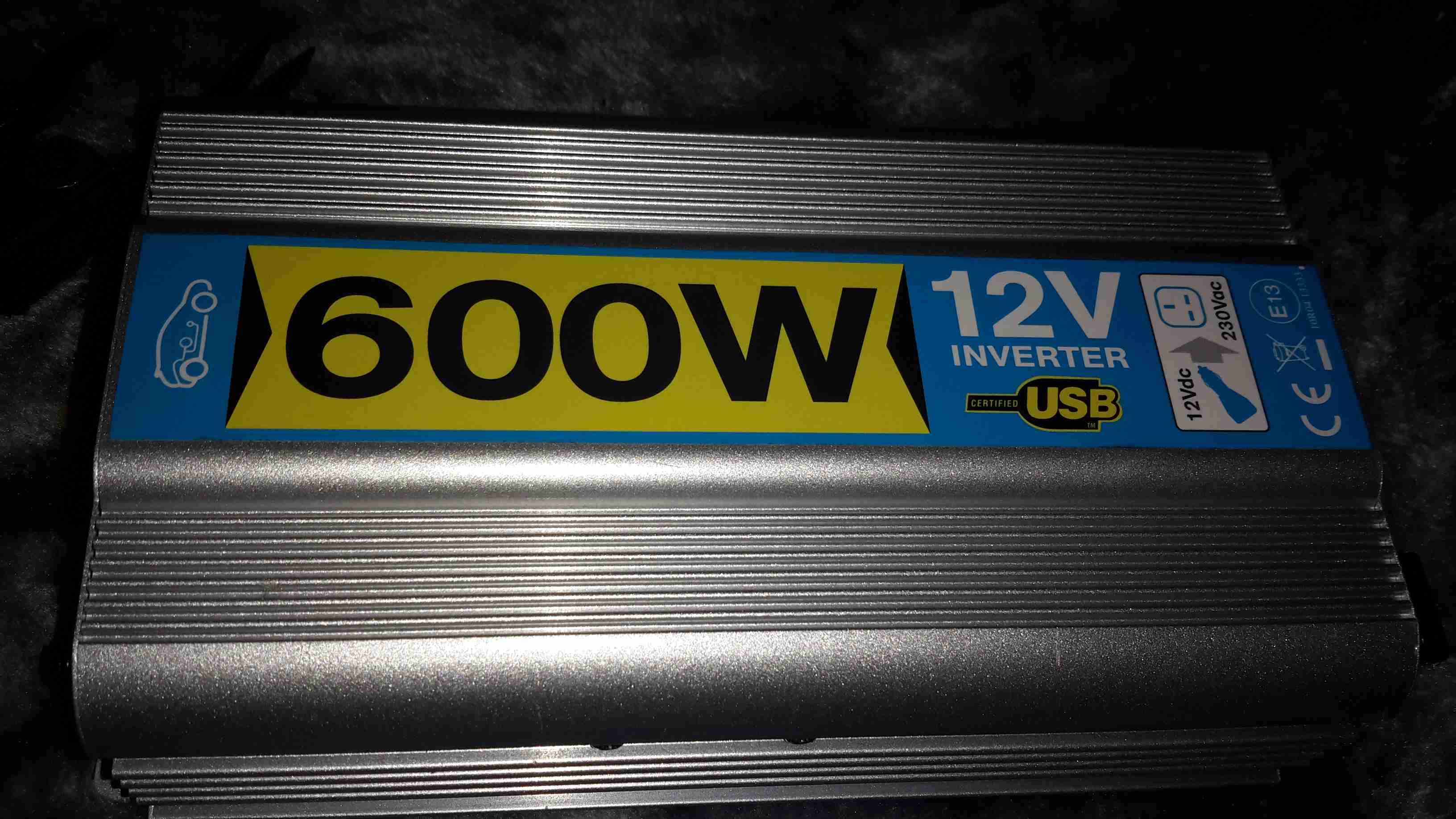
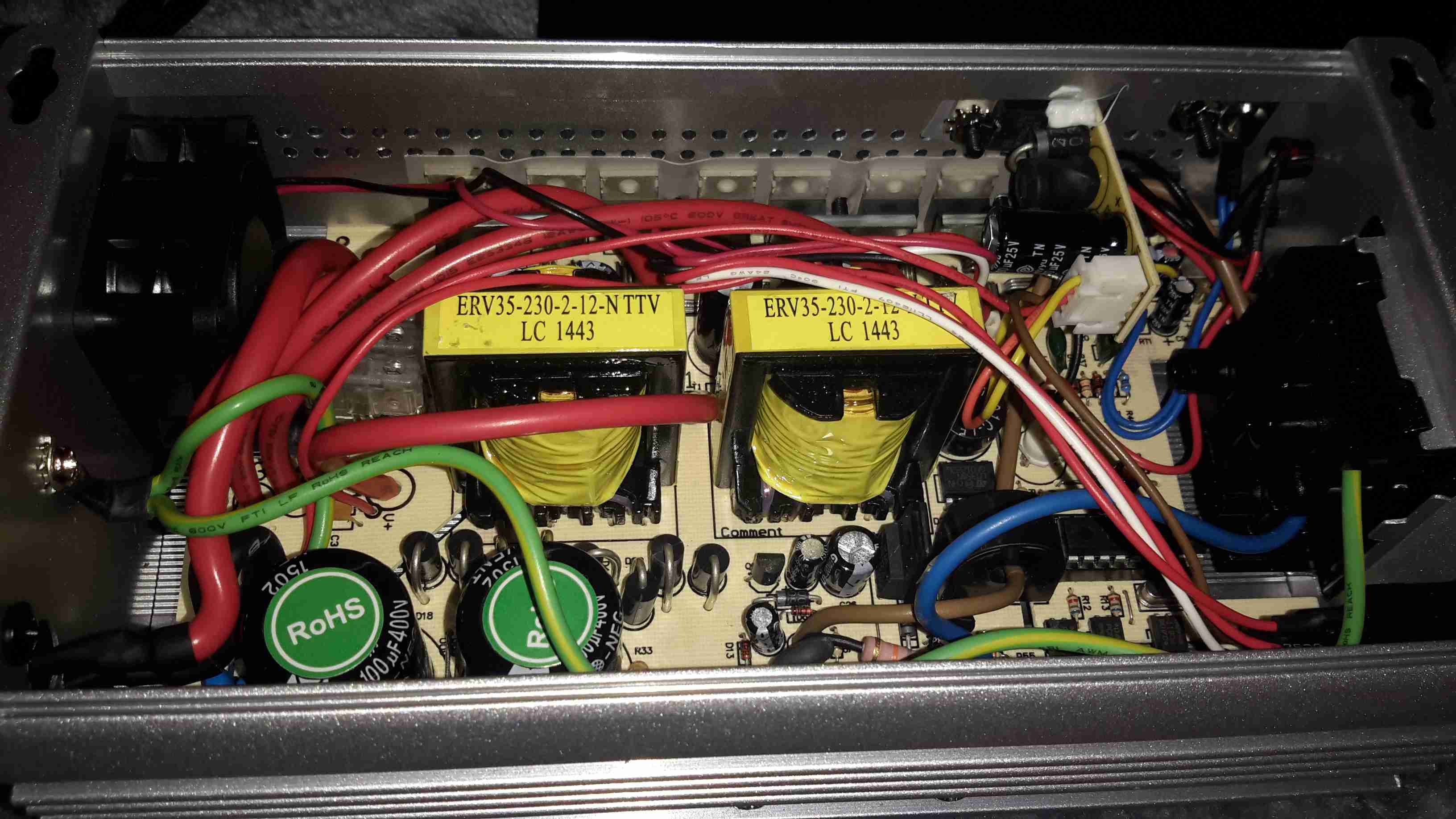
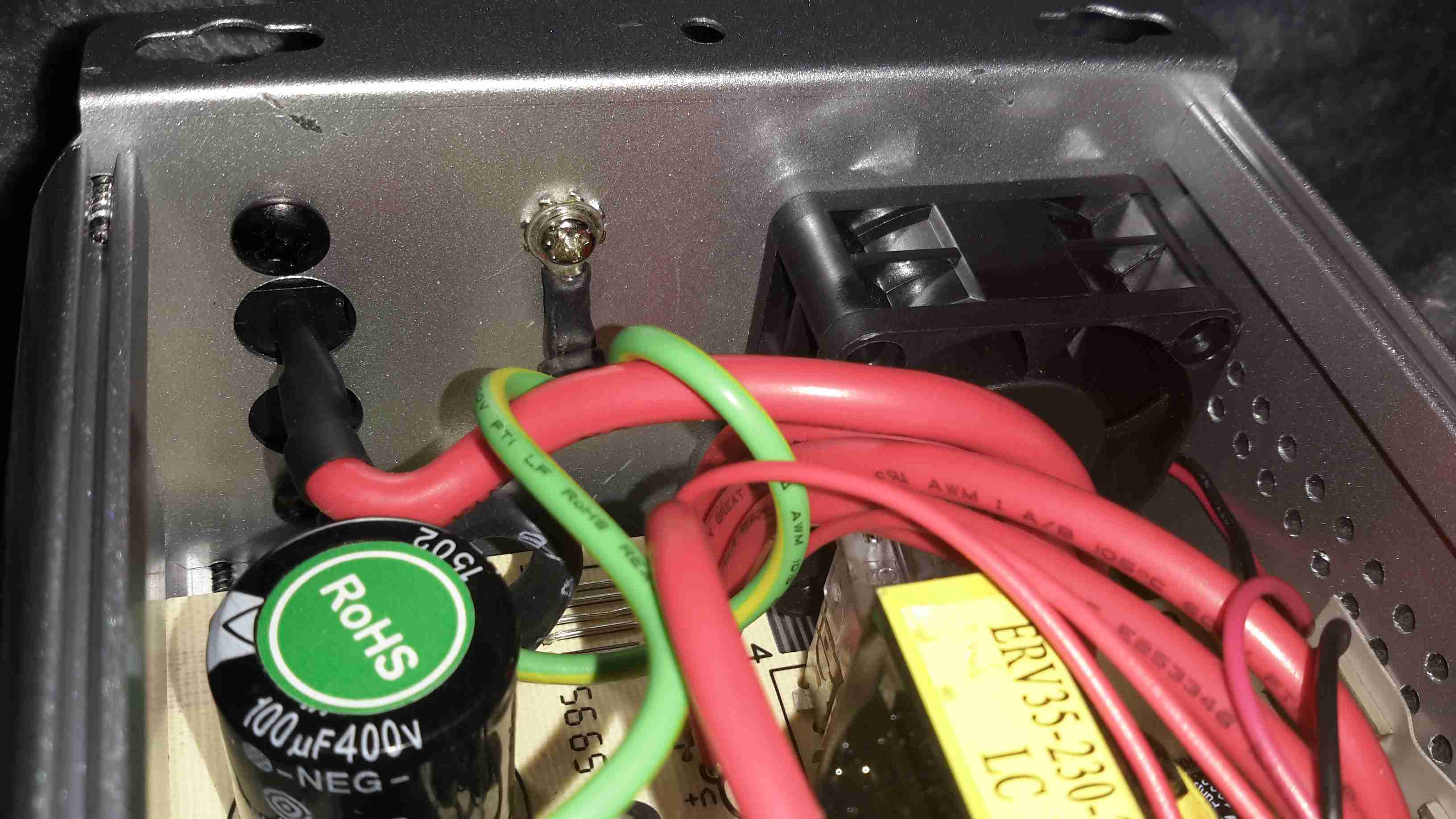
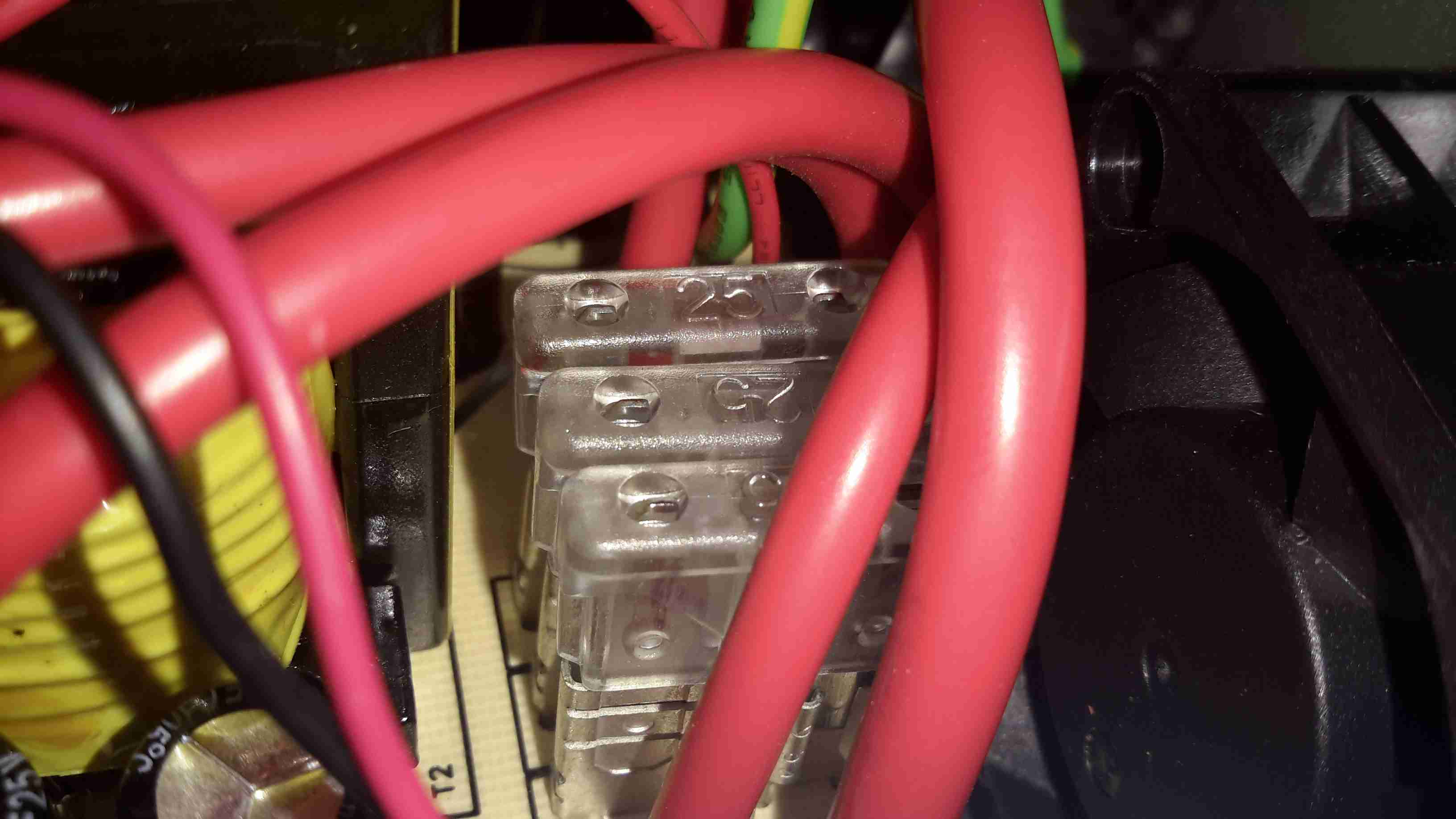
Tucked under the DC outputs are a pair of panel sockets for the 600W inverter. This cheapo Maplin unit is only usually used to pump up air beds, so I’m not expecting anyone to pull anything near max output, but a warning label always helps.

Power Socket Wiring
Power Socket Wiring

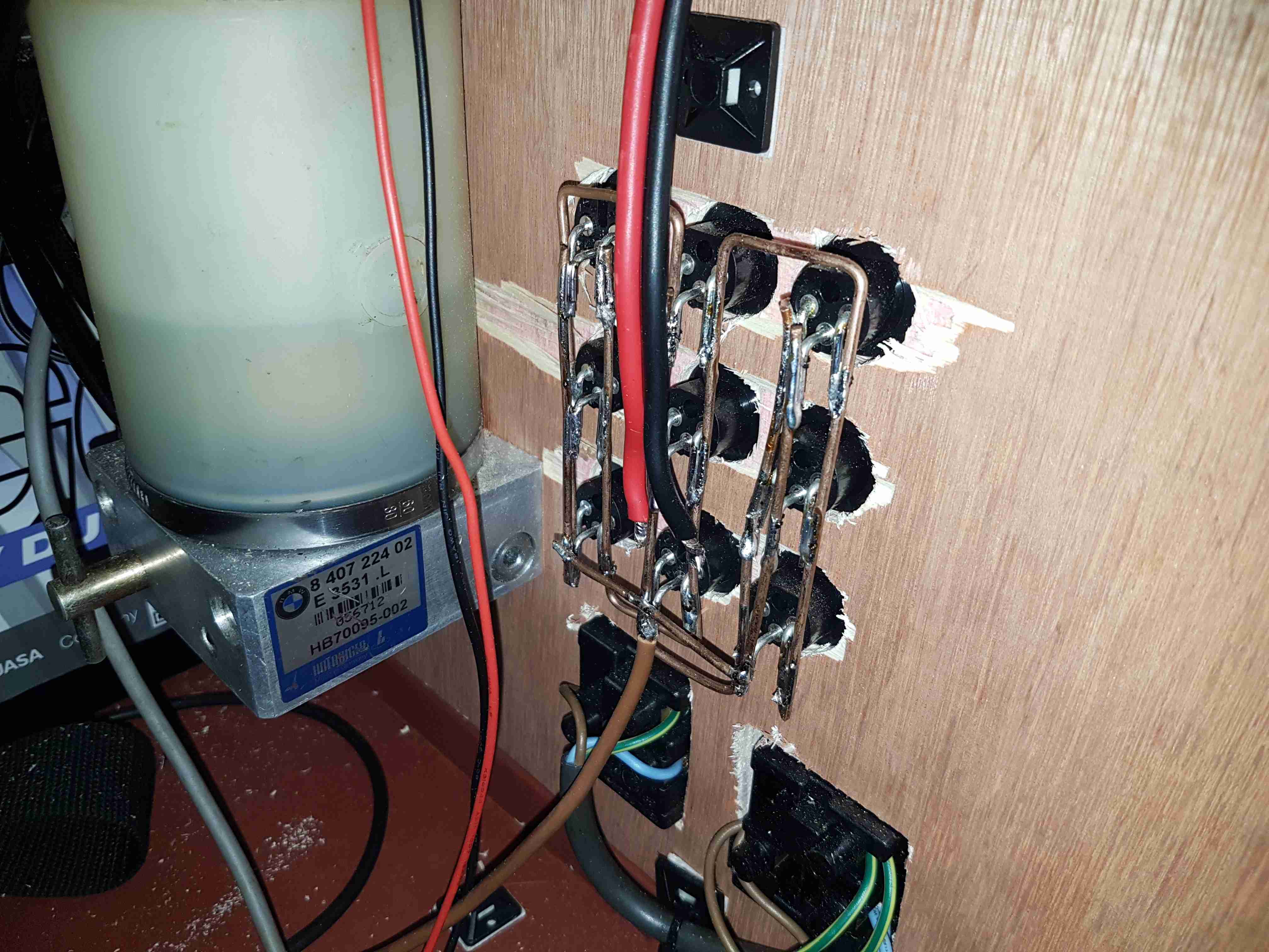
Behind the front panel is the hardwiring for the power sockets. The DC jacks are connected together using 2mm solid copper wire, bent into bus bars.The mains wiring underneath is a simple radial circuit straight from the inverter. The large cylinder on the left is a hydraulic pump from a BMW Z3, which runs a hydraulic cylinder for lifting the lid of the top box, used simply because I had one in the box of junk.

Fuel Pump
Fuel Pump

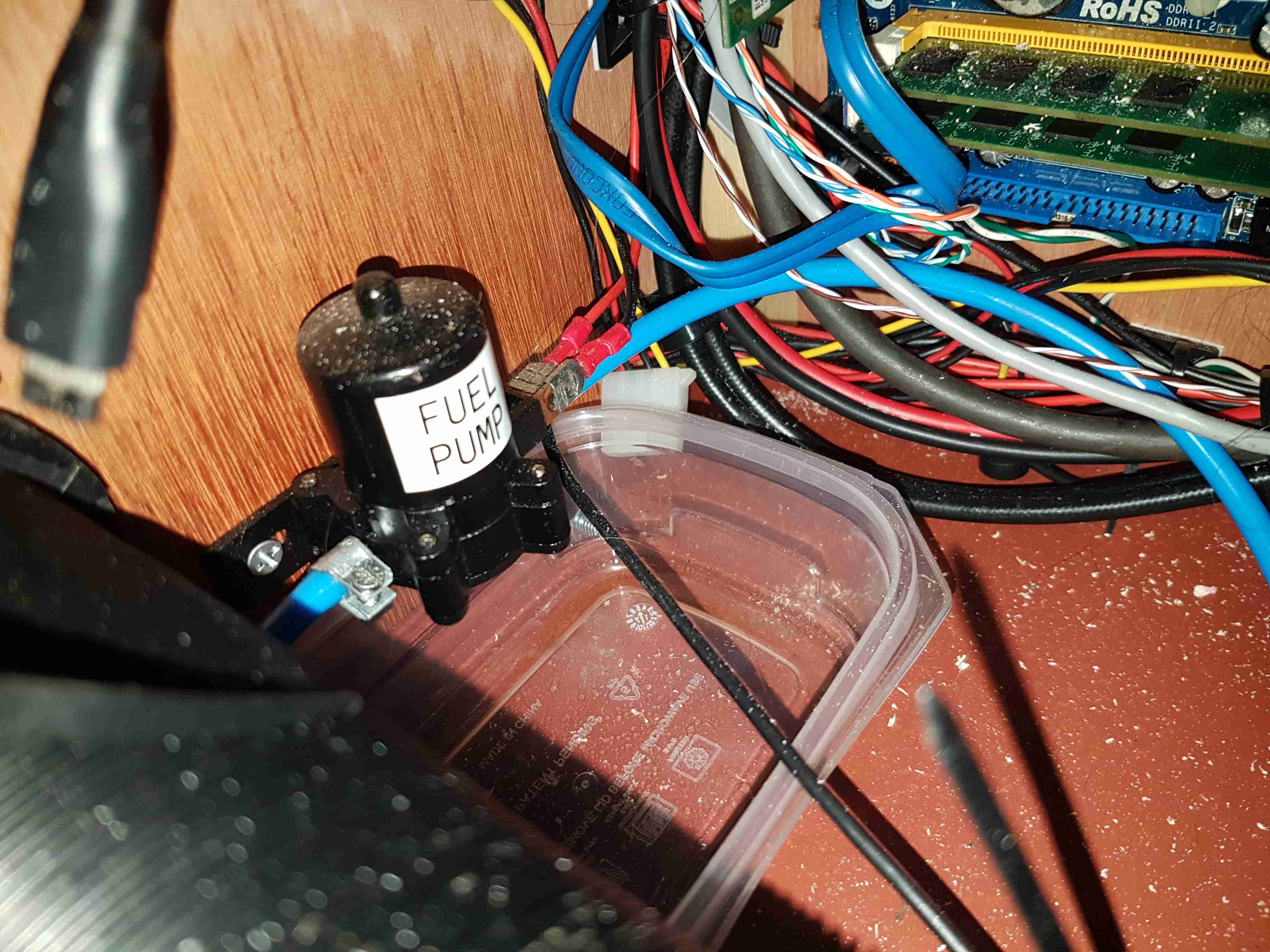
External fuelling is dealt with by a small gear pump, this is used to fuel up the Optimus Stove & Petromax Lantern. This is in fact a car windscreen wash pump, but it has coped well with pumping hydrocarbons, it currently has a small leak on the hose connections, but the seals are still entirely intact.

Remote Relays
Remote Relays

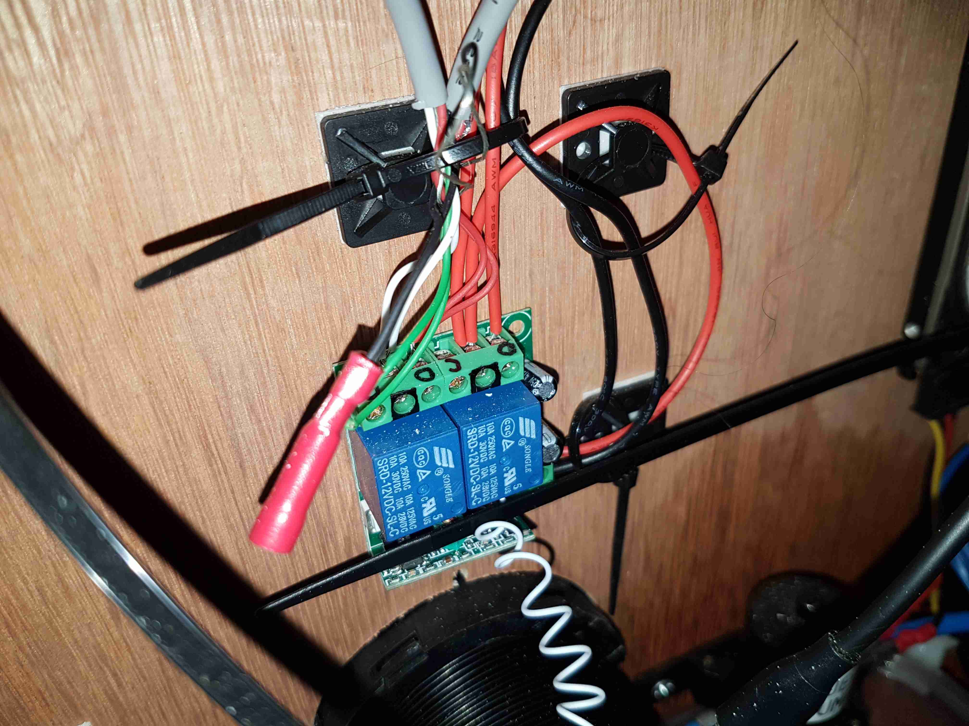
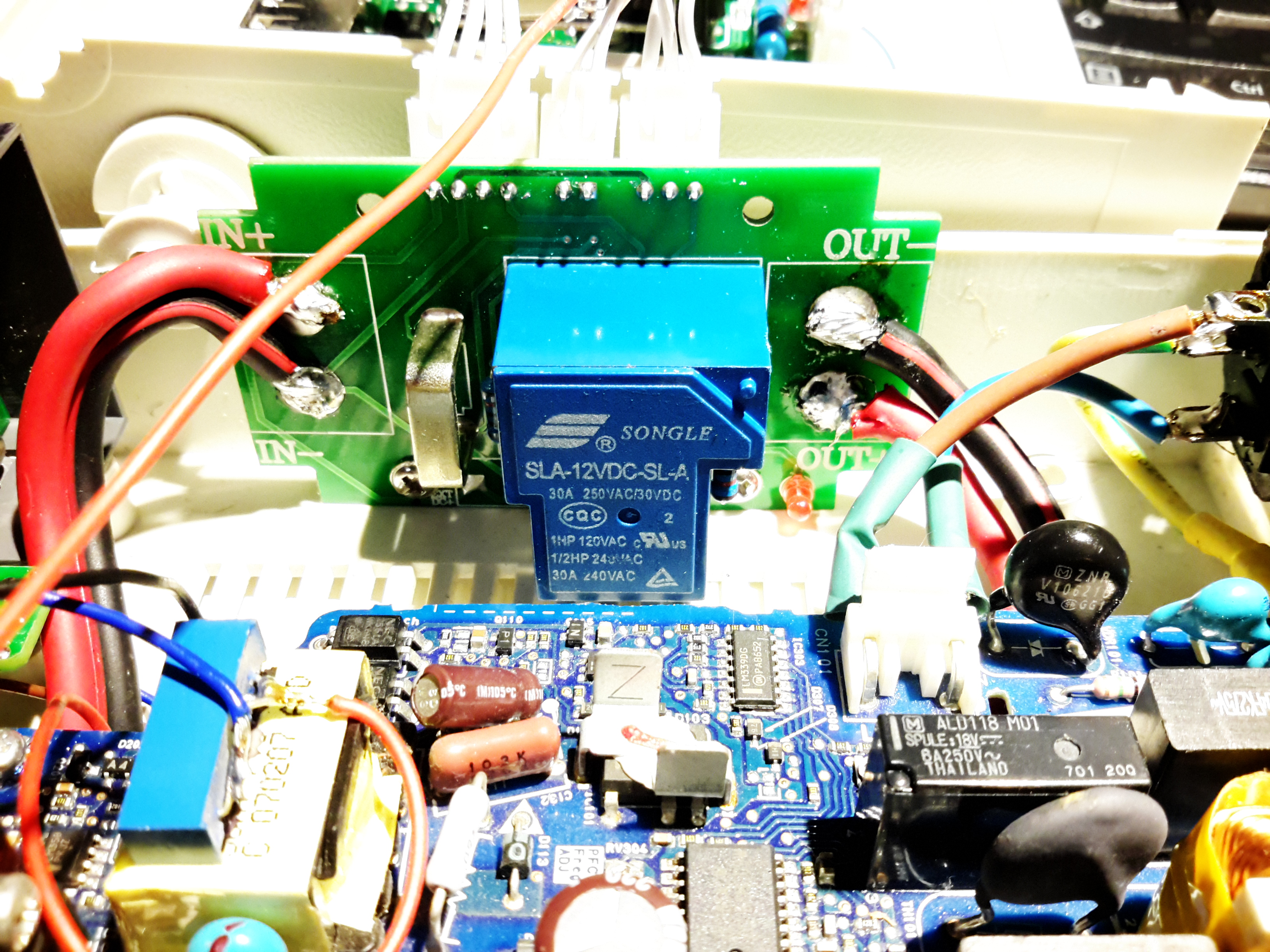
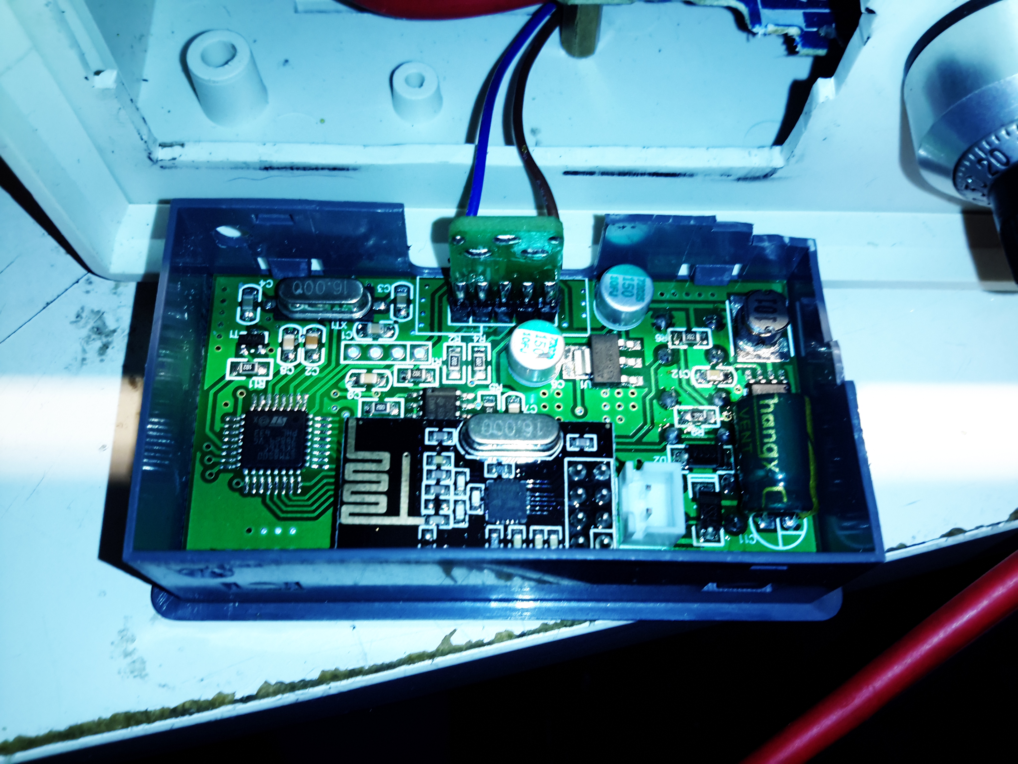
There’s a small remote relay module here, for switching the DC output for lighting & the heater from afar. Very useful when it’s dark, since there’s no need to fumble around looking for a light switch. A car-style fob on my keyring instead.

Heater Timer
Heater Timer

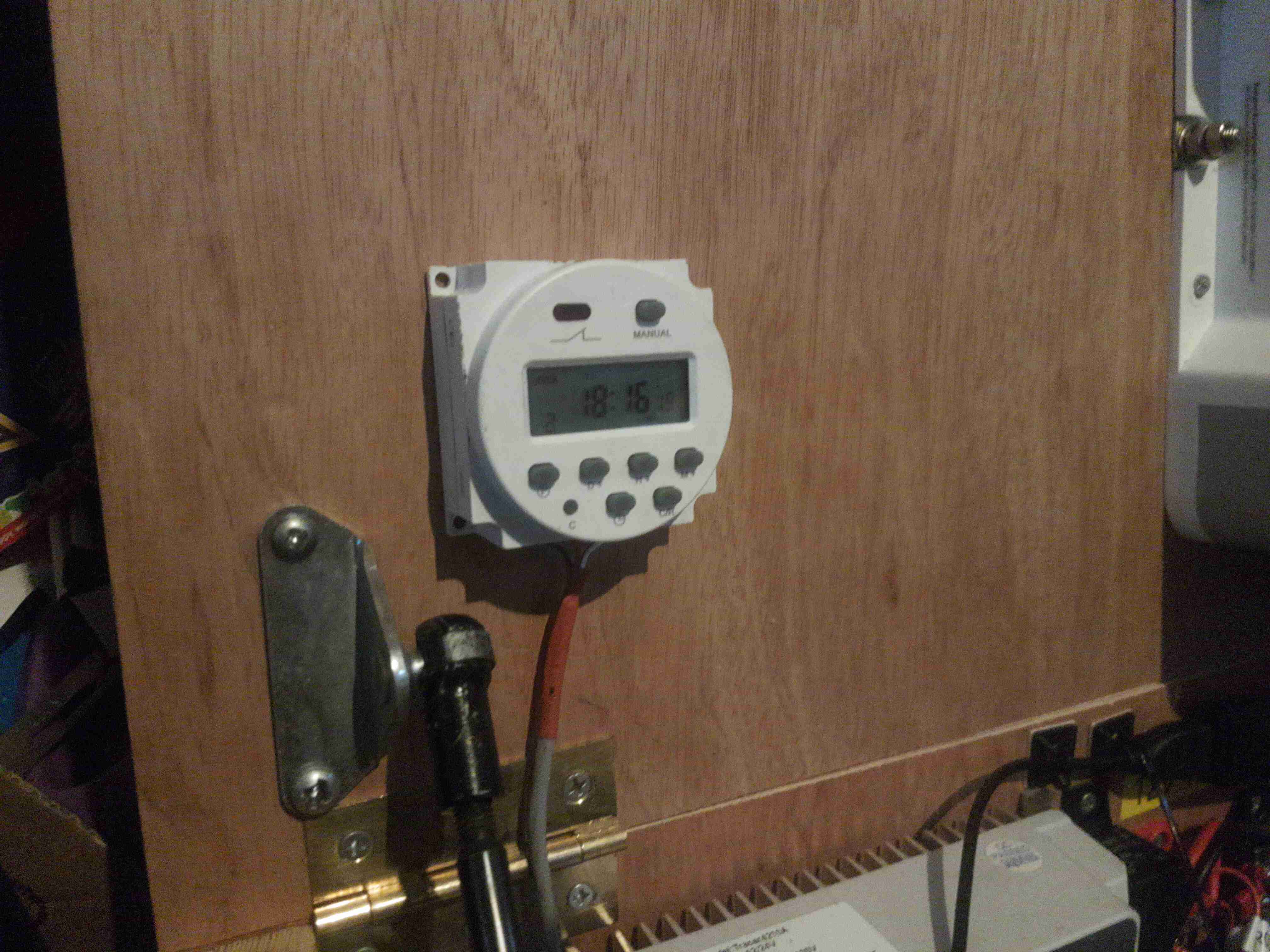
Since the Eberspacher 701 controller I have is an ex-BT version, it’s very limited in it’s on time, a separate timeswitch is fitted to control the heater automatically. Being able to return to a nice warm tent is always a bonus.
Just to the left can be seen the top ball joint for the hydraulic cylinder that lifts the top of the box.

Battery Charger
Battery Charger

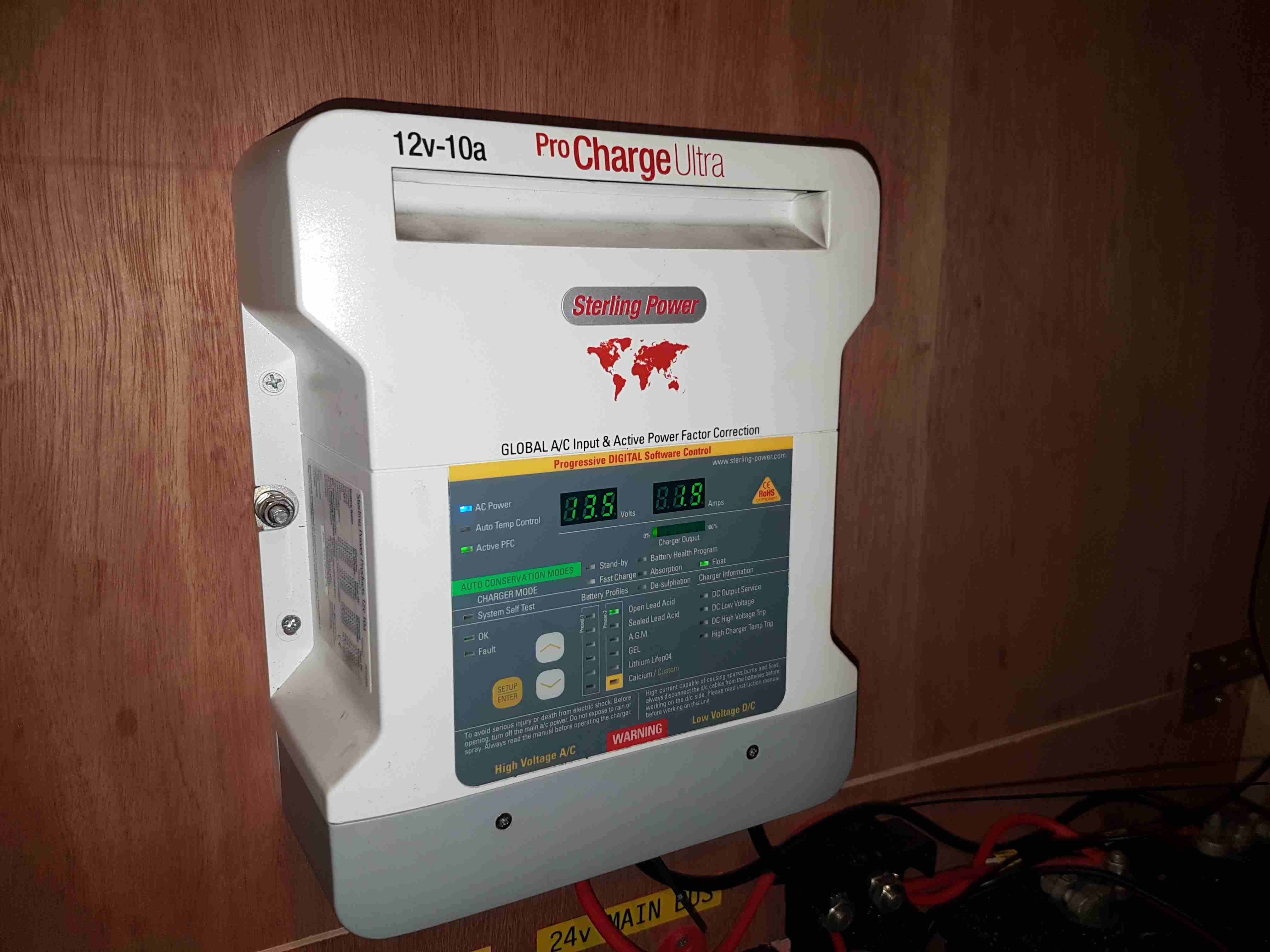
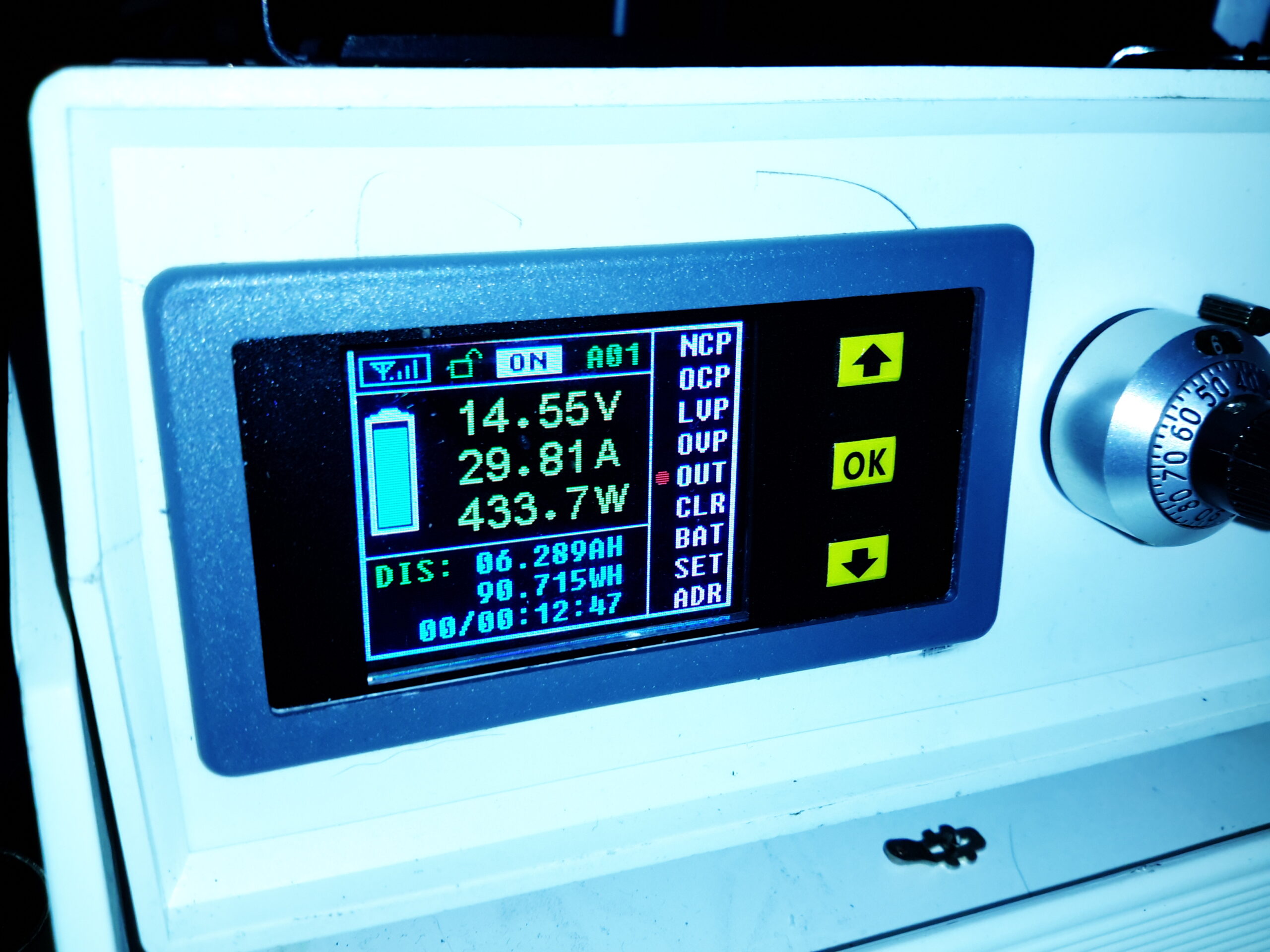
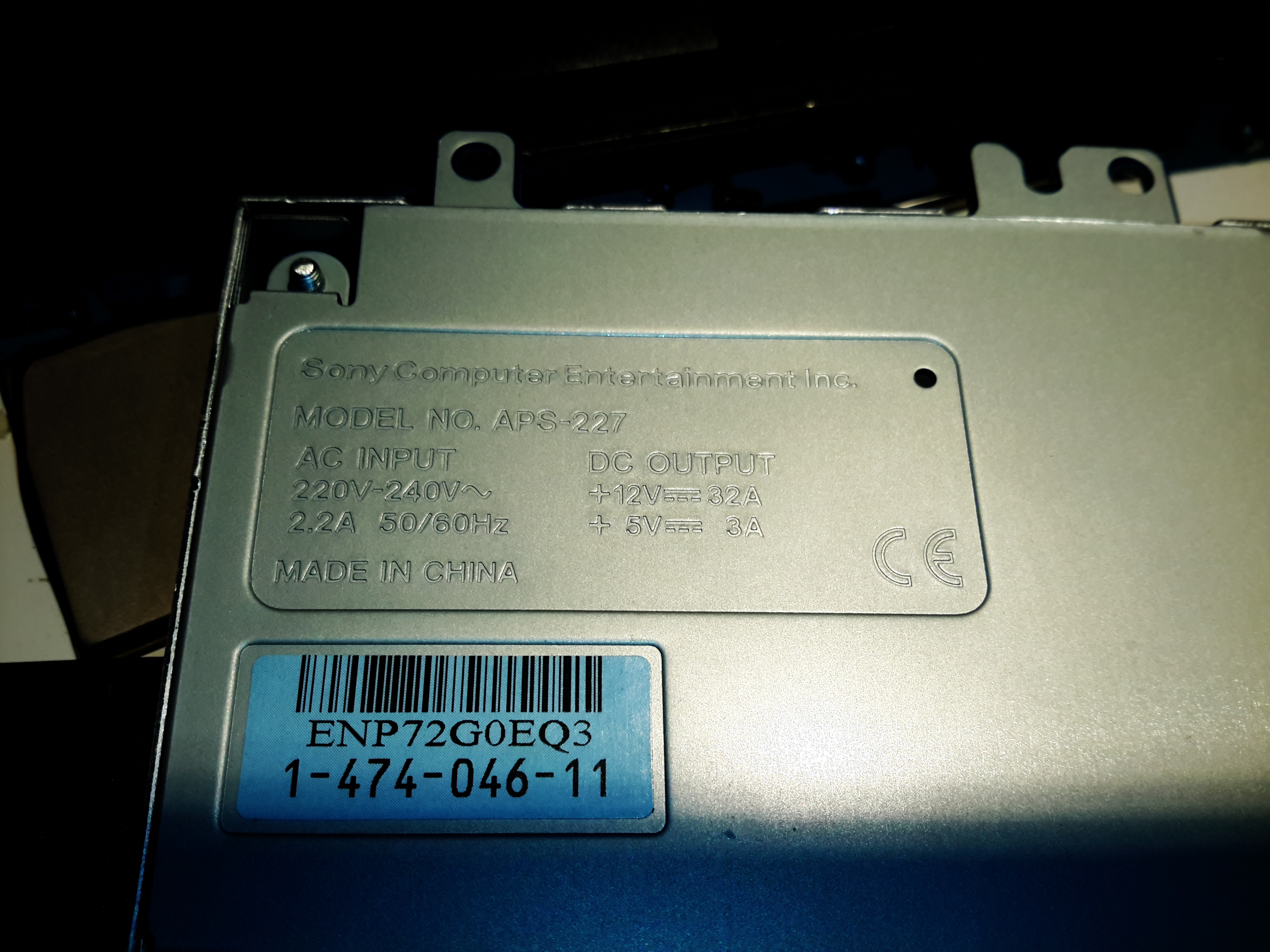
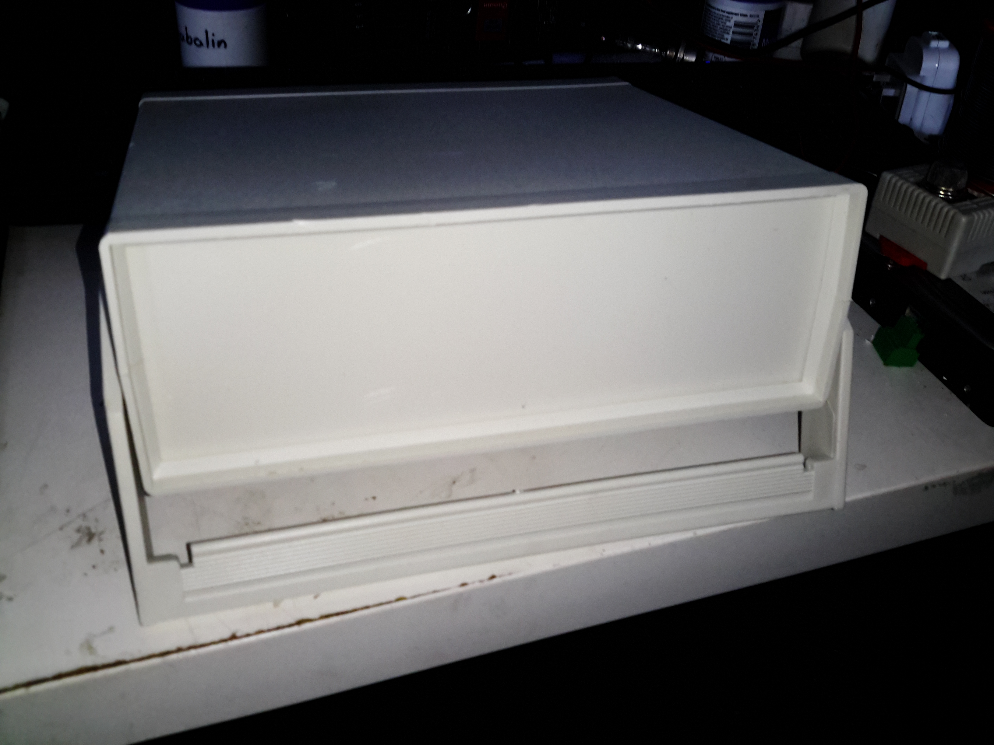
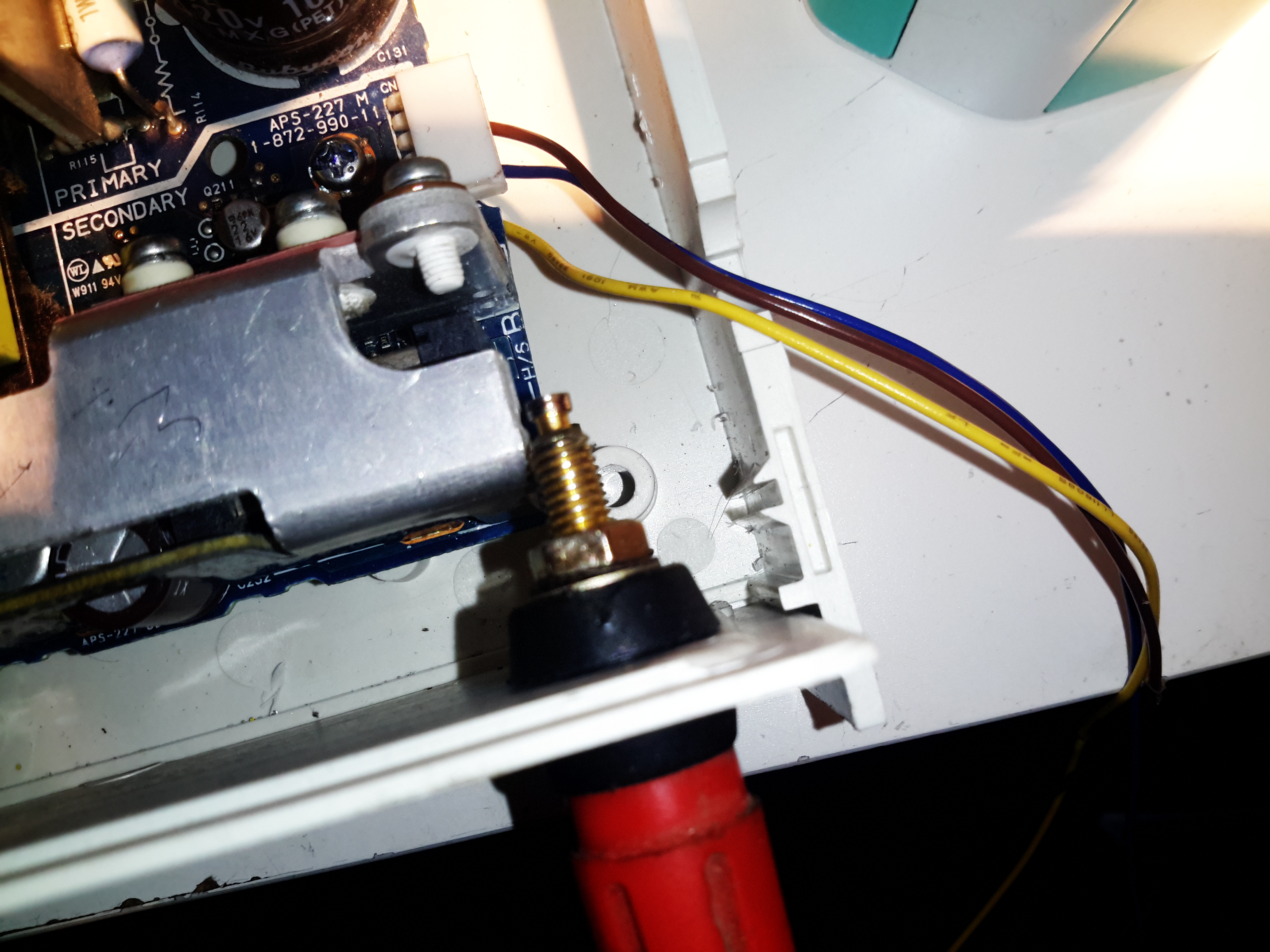
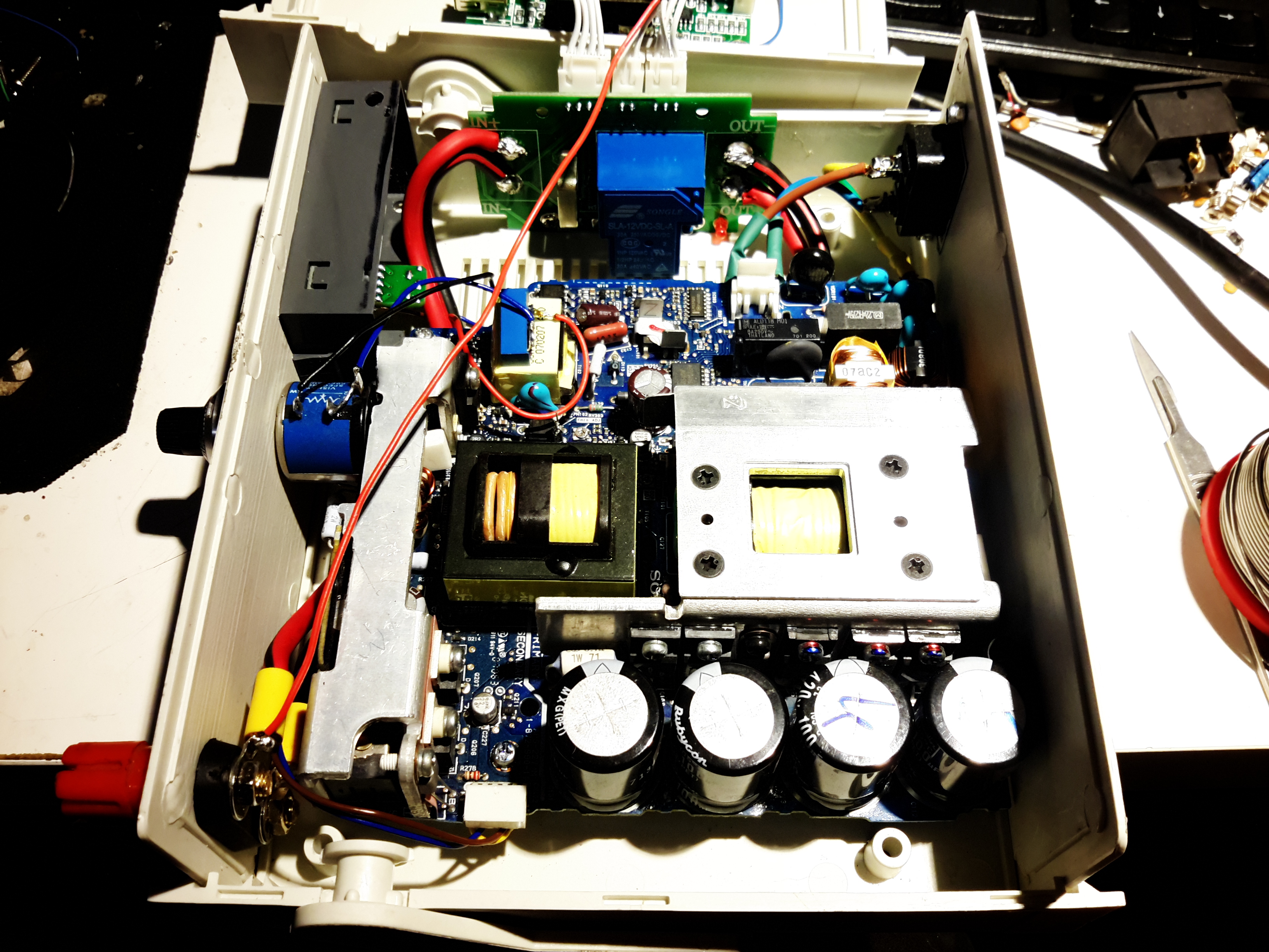
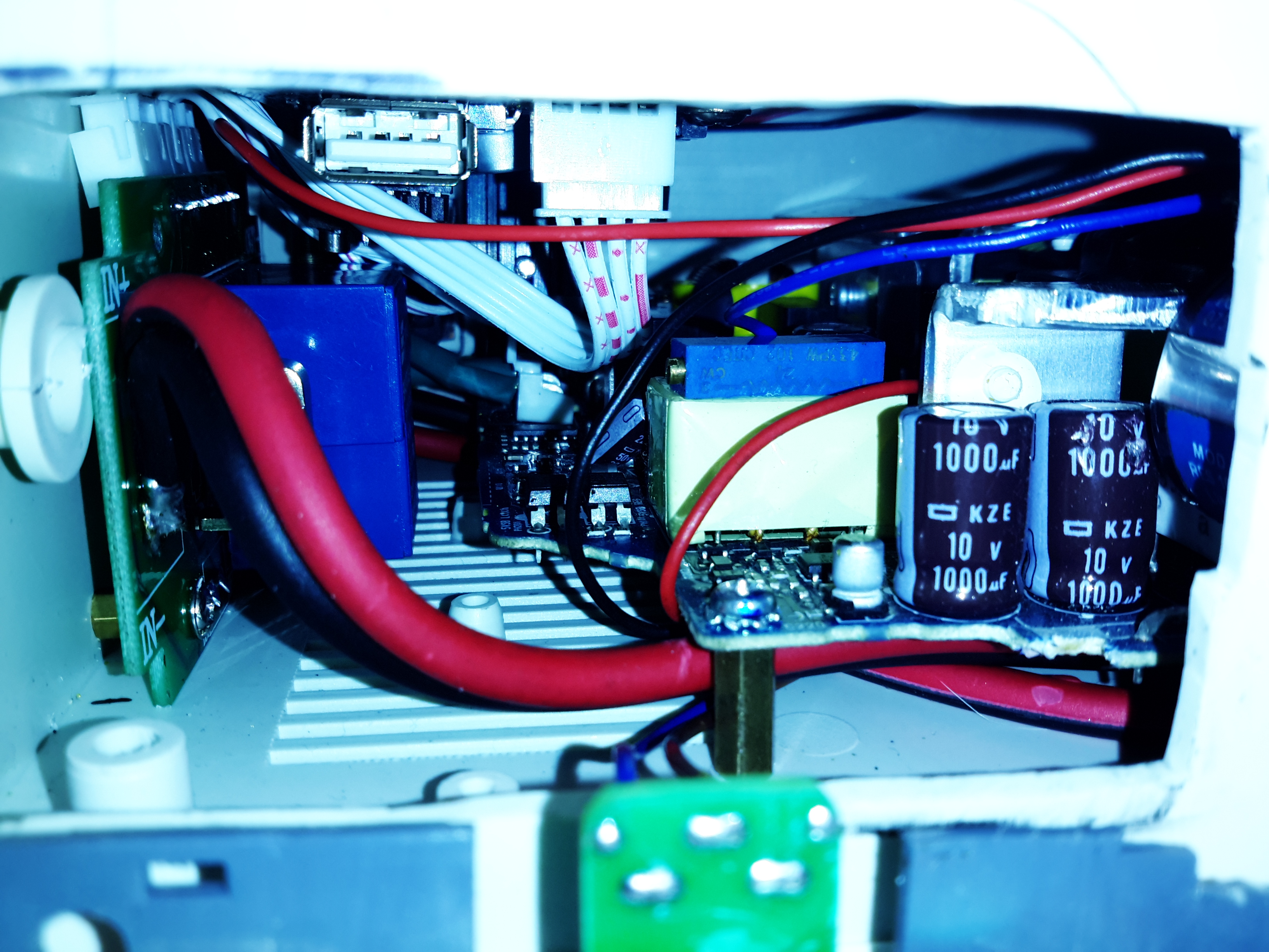
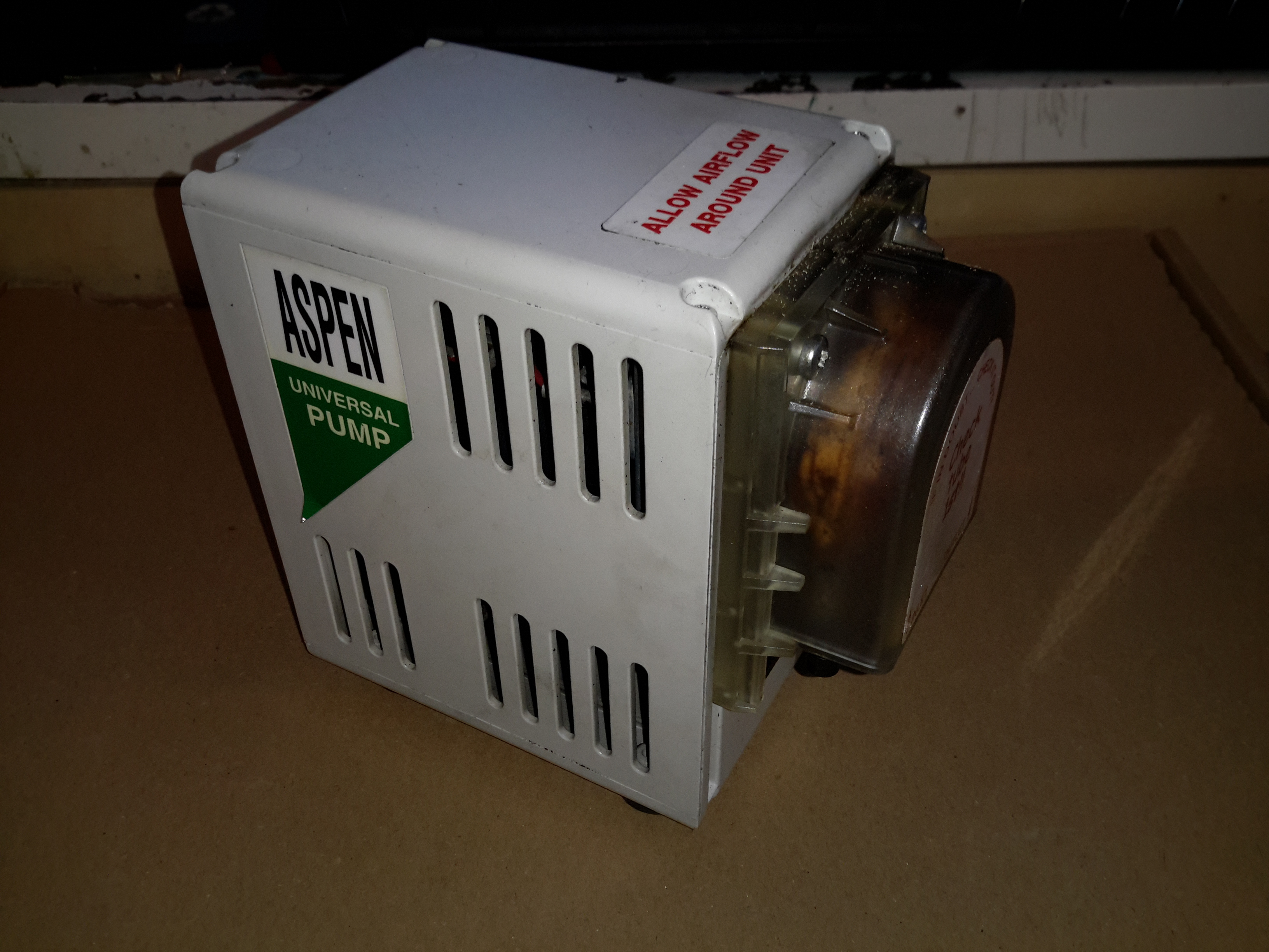
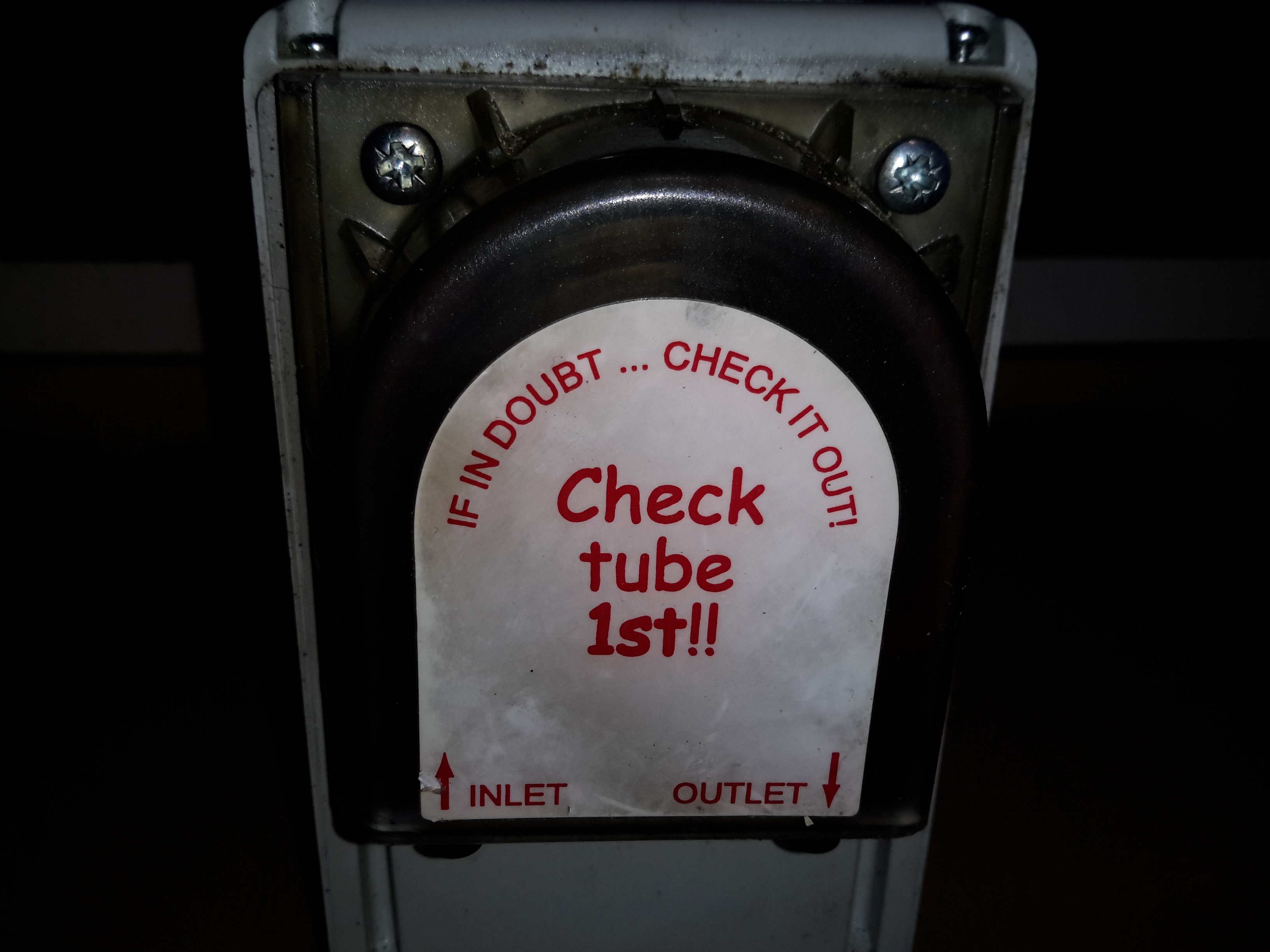
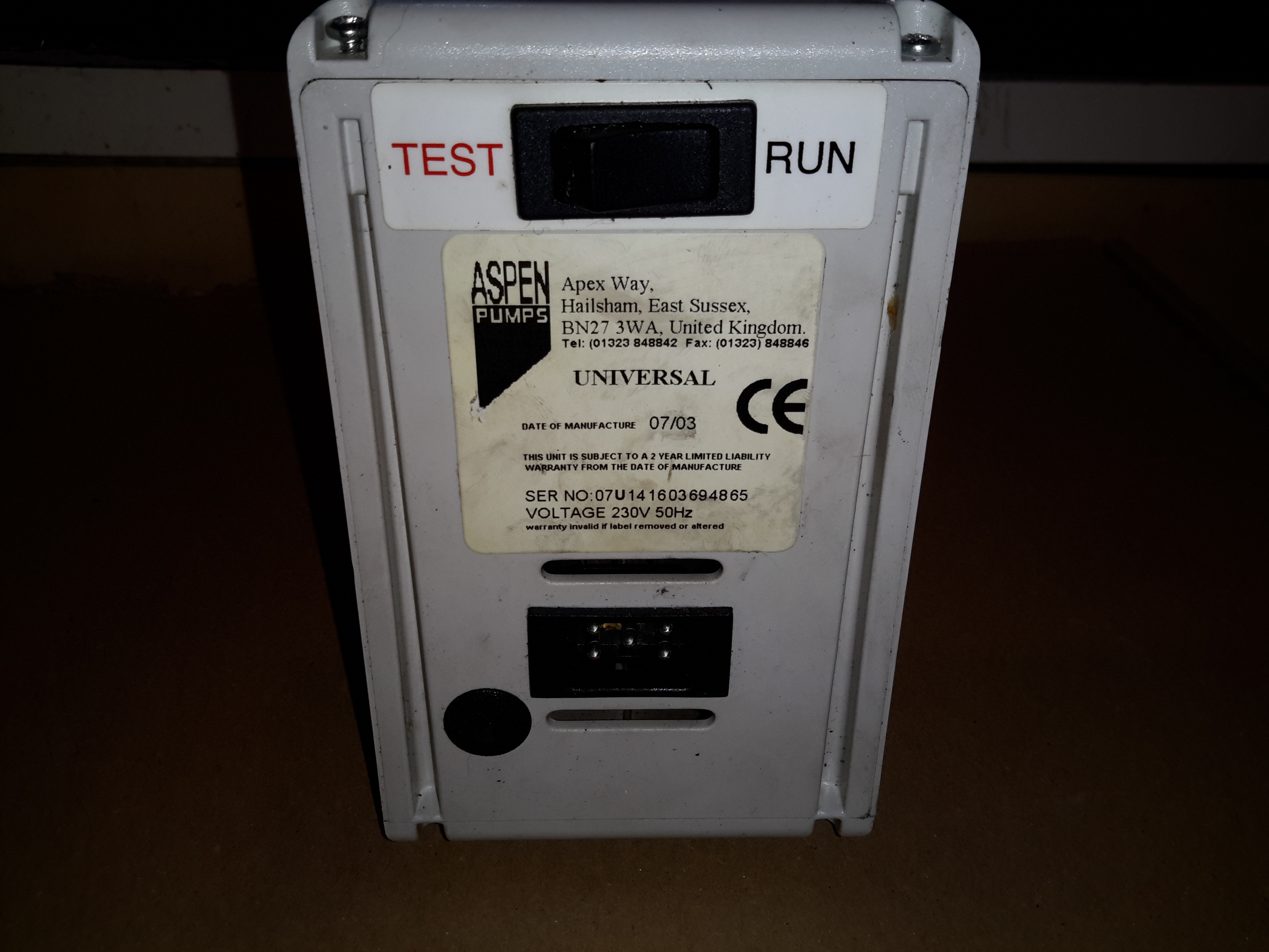
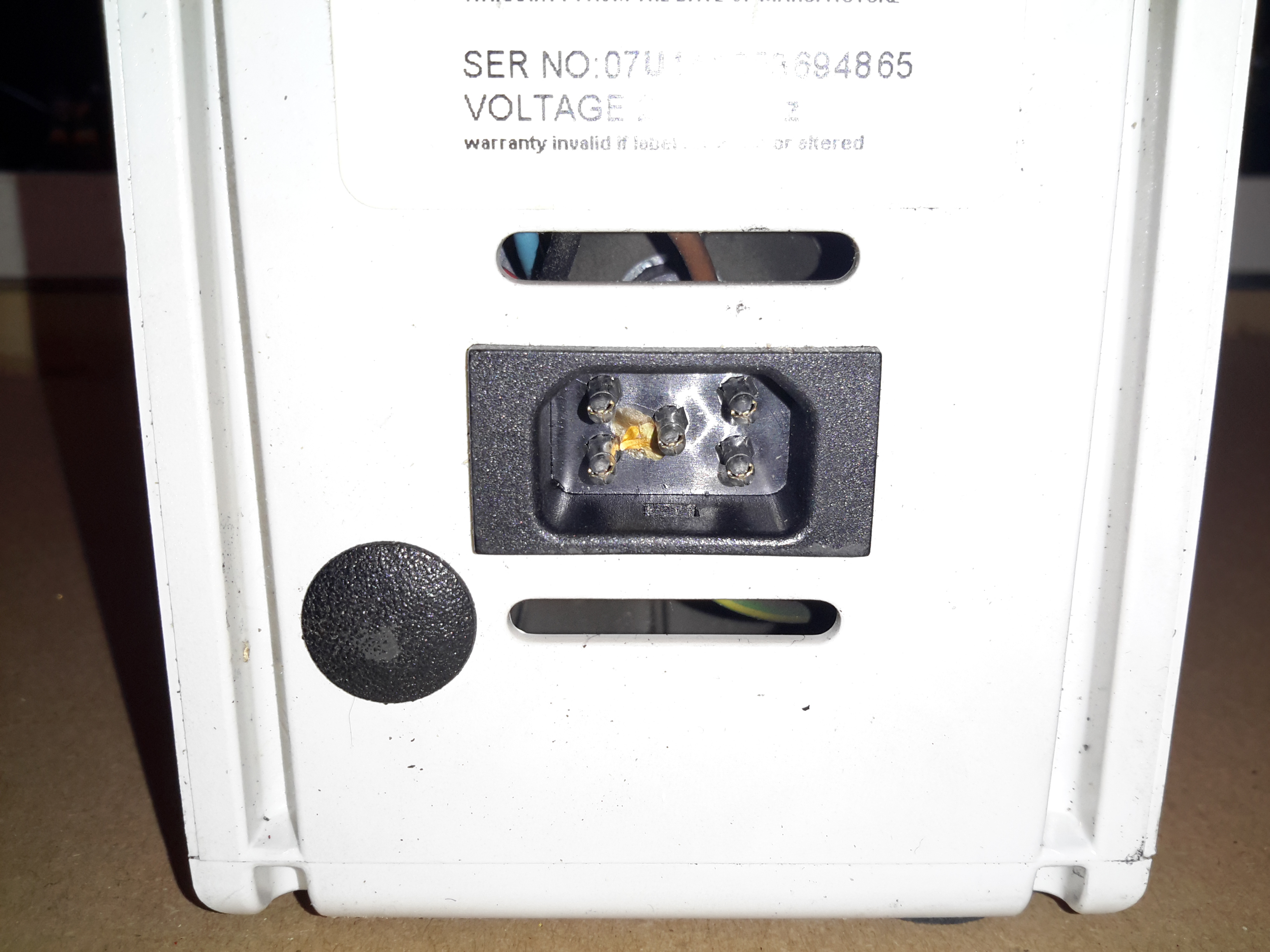
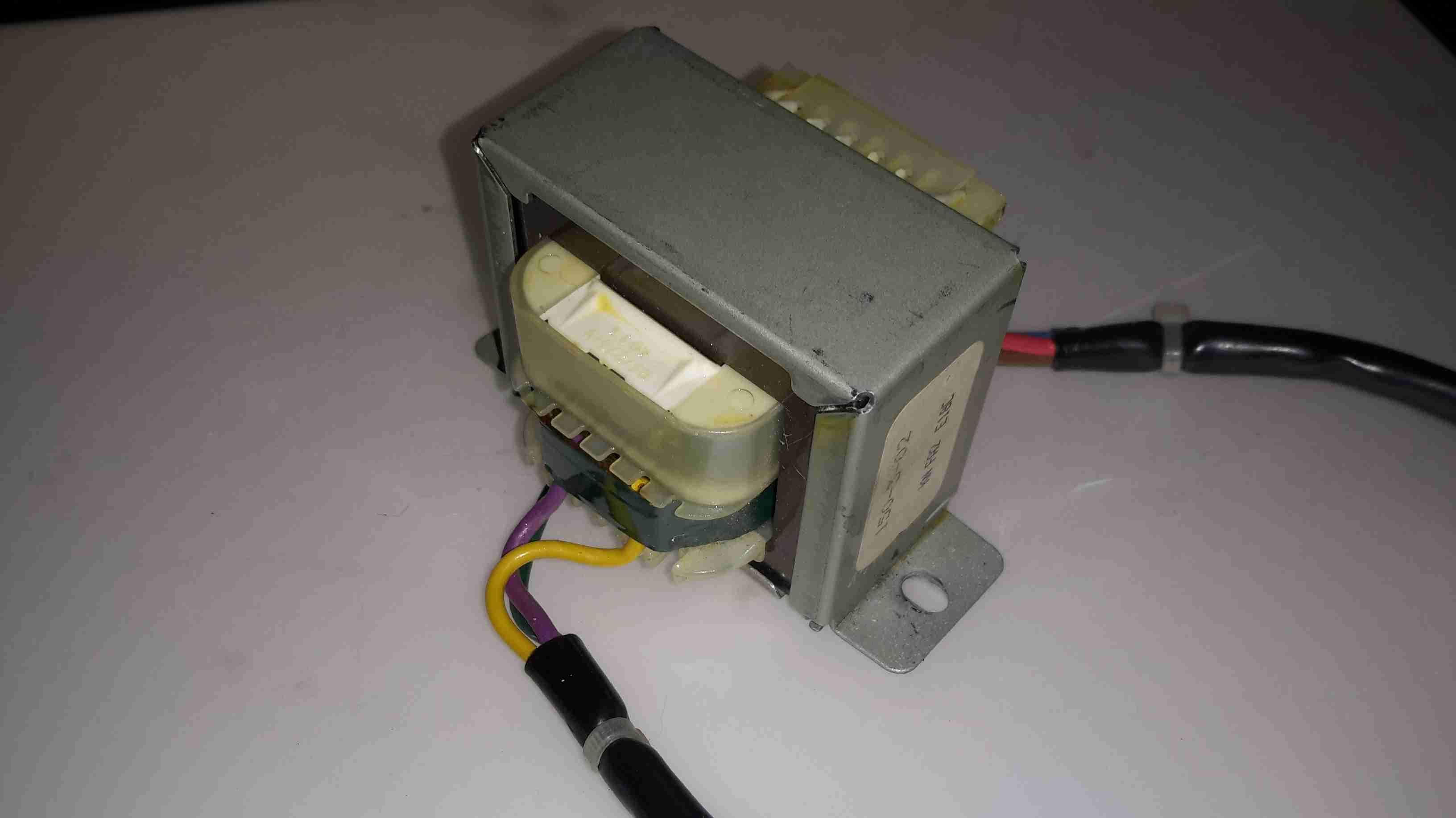
The final large component is the battery charger. This unit will maintain the battery when the trolley isn’t being used.

Router Motherboard
Router Motherboard

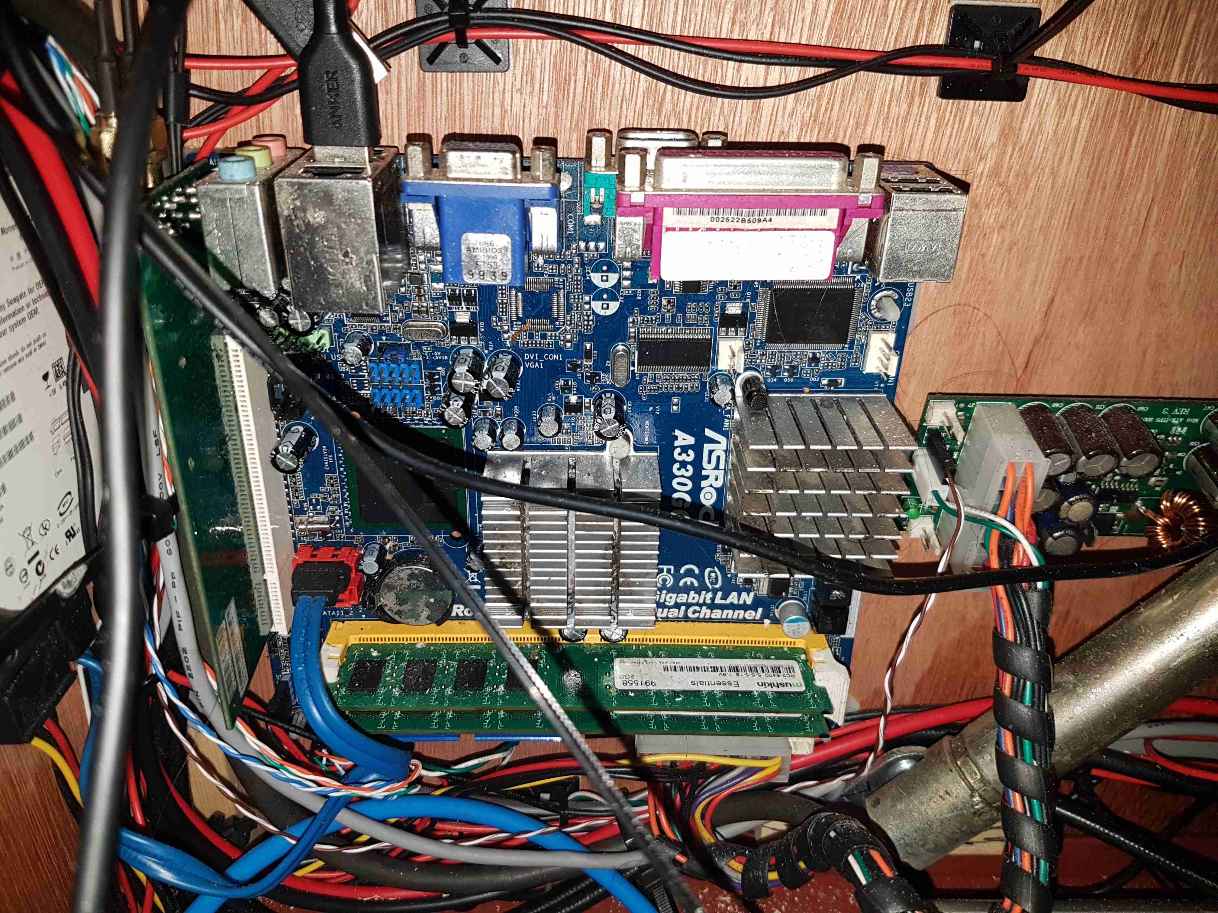
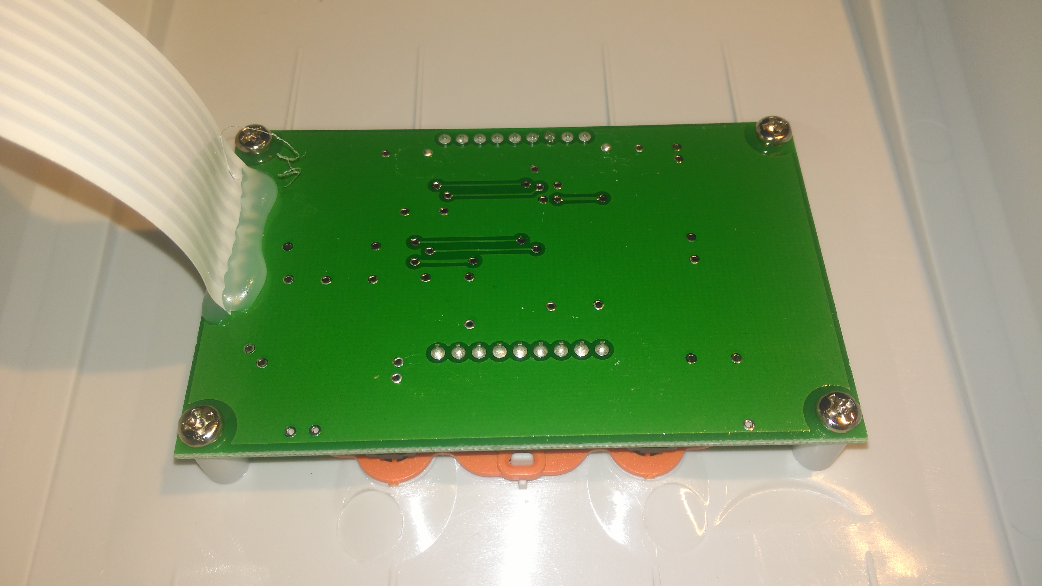
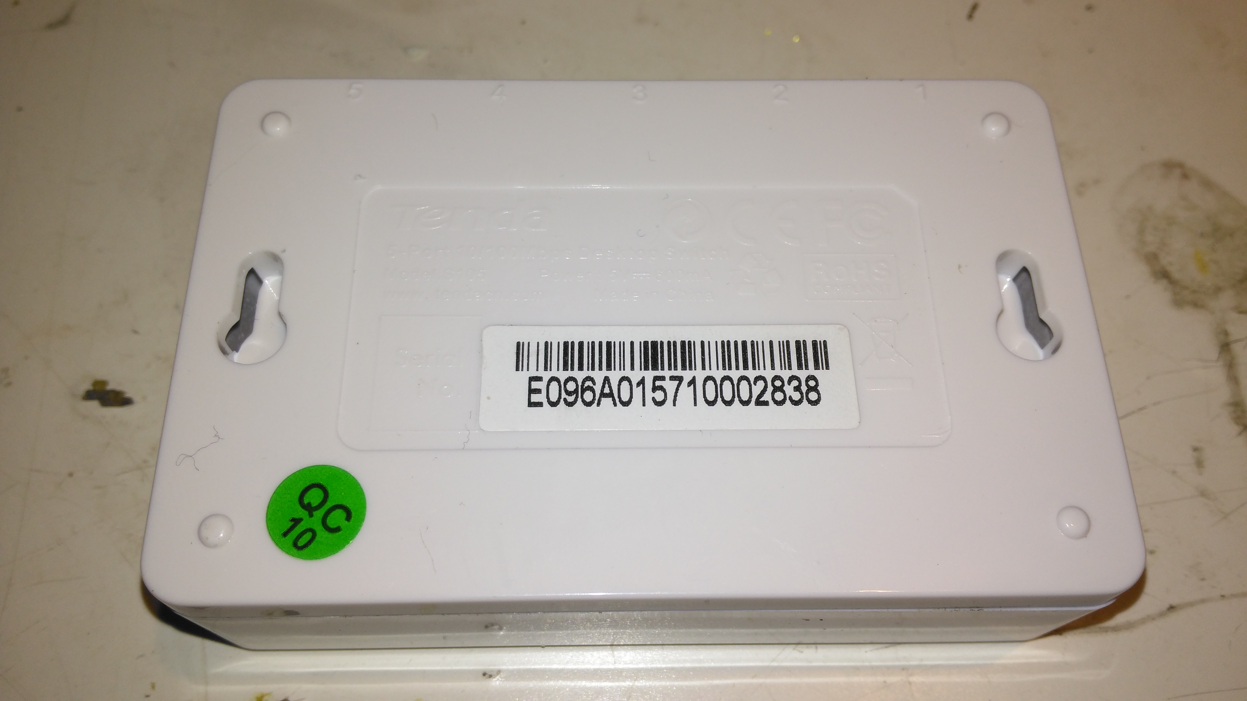
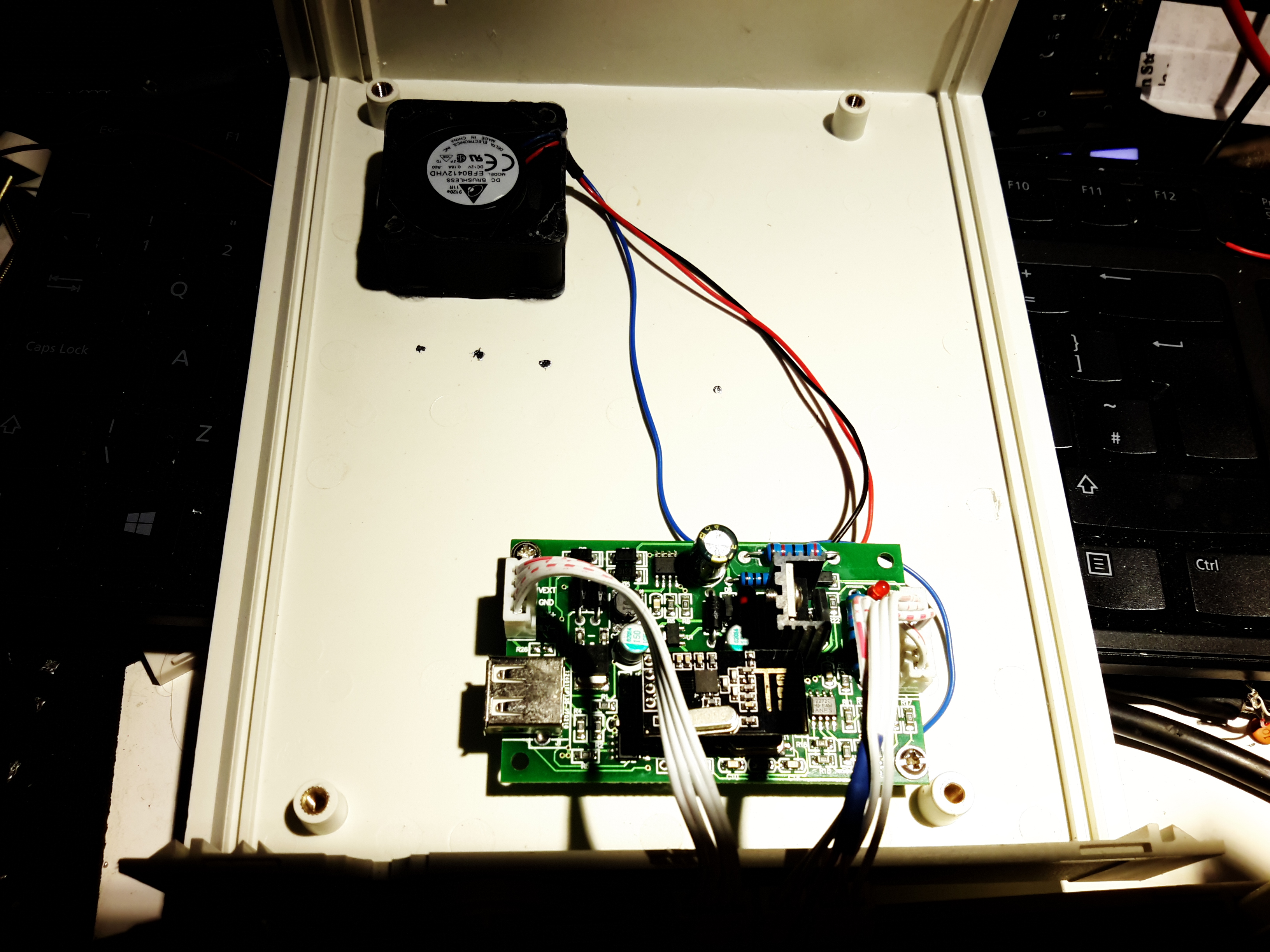
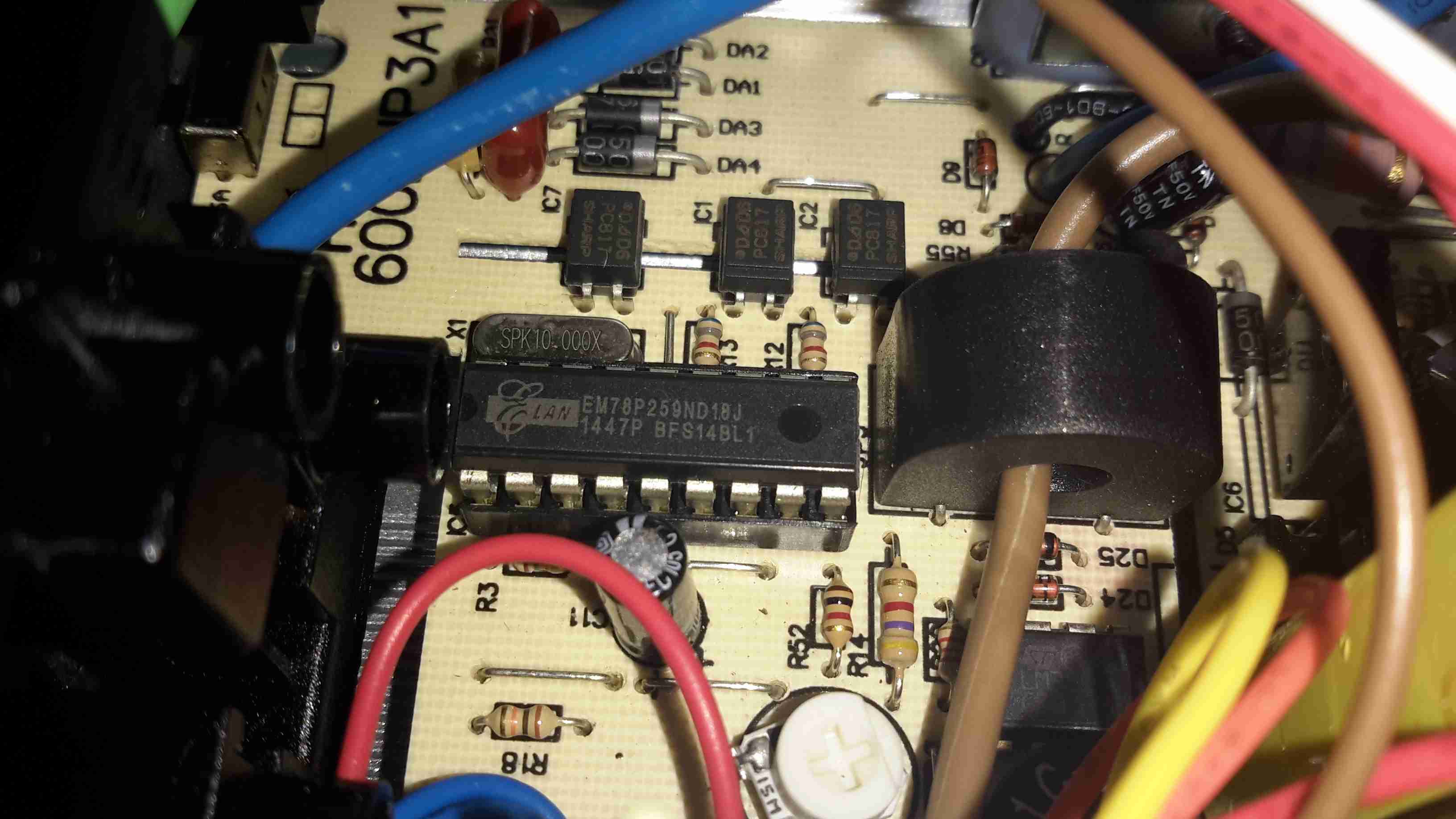
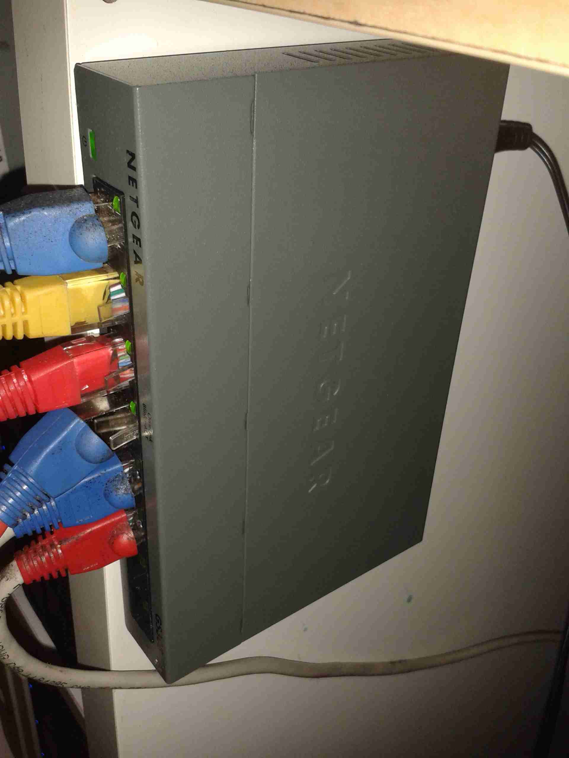
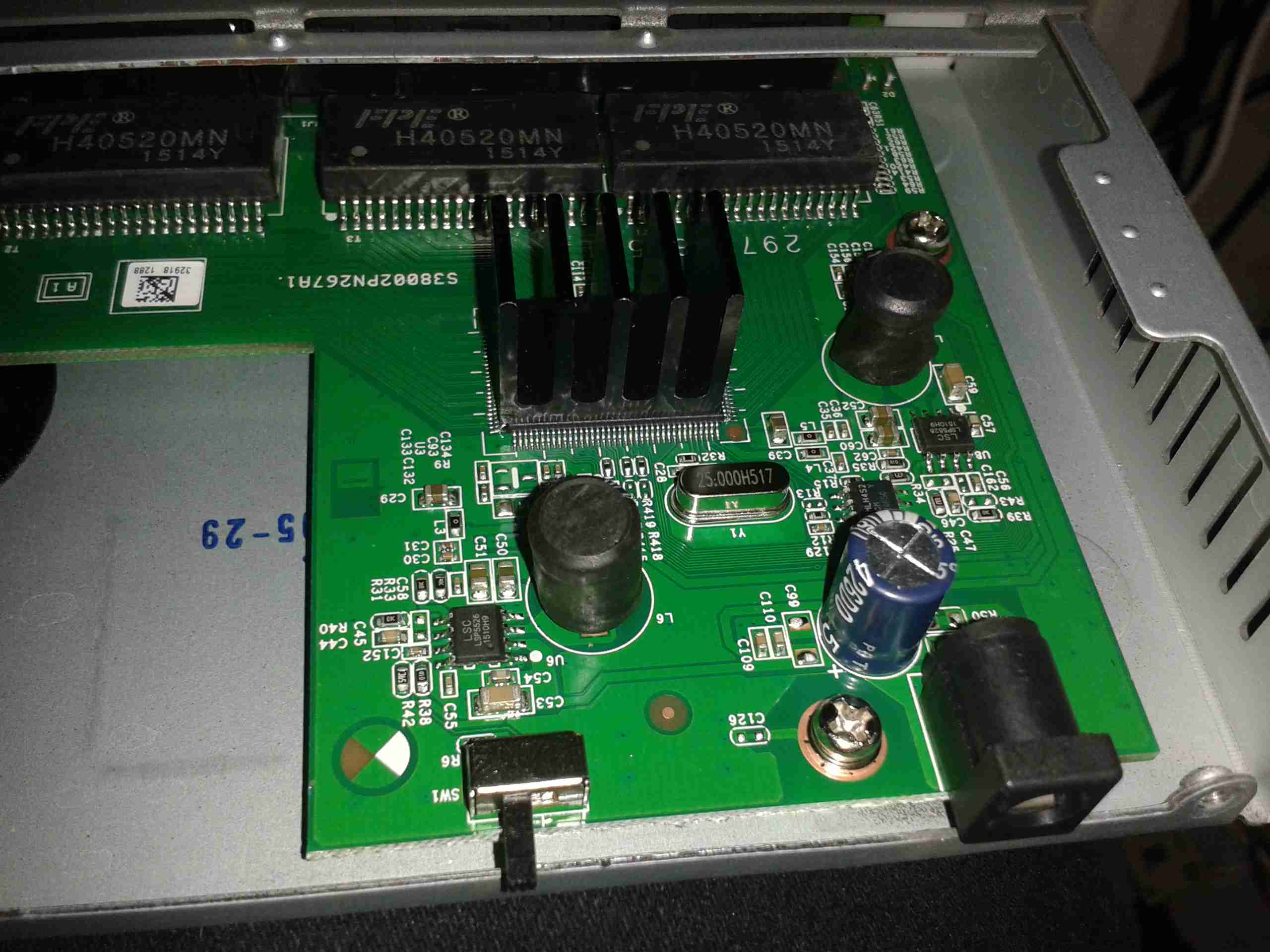
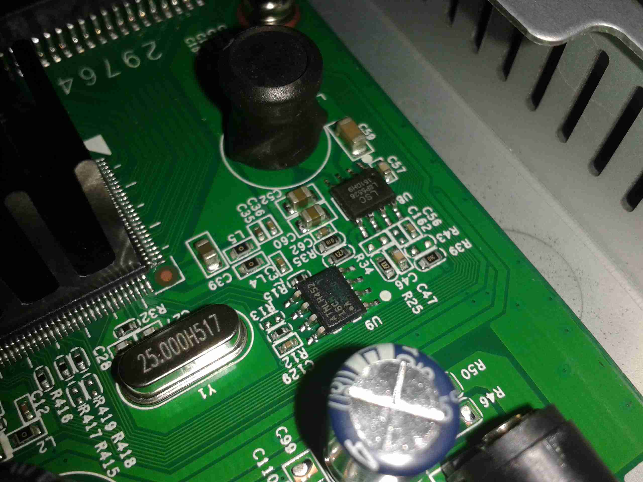
On the left side is the old Atom motherbaord used to provide a 4G router system. This unit gets it’s internet feed from a UMTS dongle & provides a local WiFi network for high speed connectivity. The bottom of the hydraulic cylinder is visible in the bottom right corner.

Fuel Tank Completed
Fuel Tank Completed

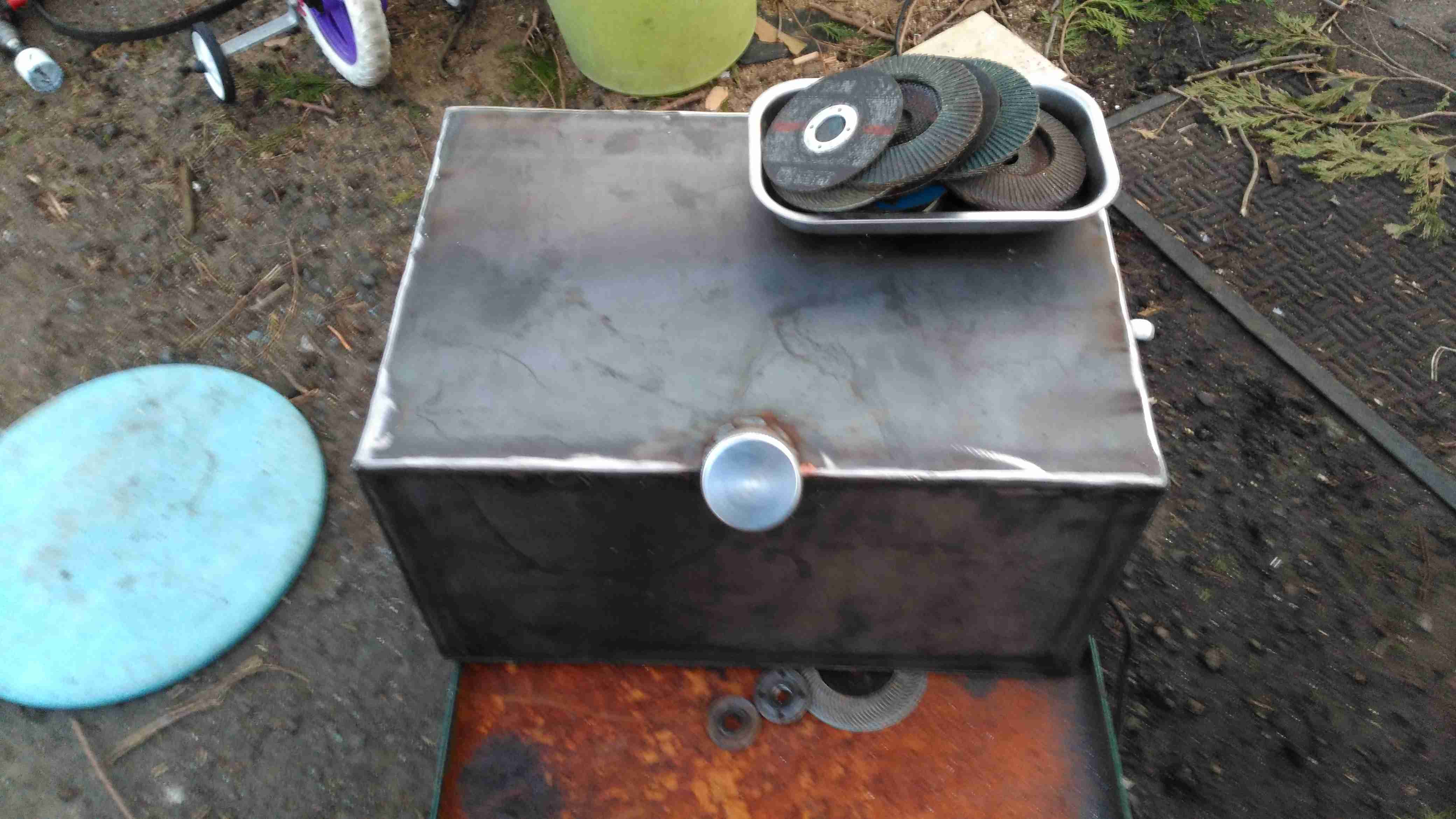
Since the Eberspacher obviously needs fuel, a tank was required. In previous years I’ve used jerry cans for this purpose, but this trolley is supposed to have everything onboard, for less setup time. The tank is constructed from 3mm steel plate, MIG welded together at the seams to create a ~40L capacity. The filler neck is an eBay purchase in Stainless Steel. No photos of the tank being welded together, as I was aiming to beat sunset & it’s very difficult to operate a camera with welding gauntlets on 😉

The tank is the same width as the trolley frame, so some modification was required, having the wheels welded directly to the sides of the tank. This makes the track wider at the rear, increasing stability.

Fuel Dip Tubes
Fuel Dip Tubes

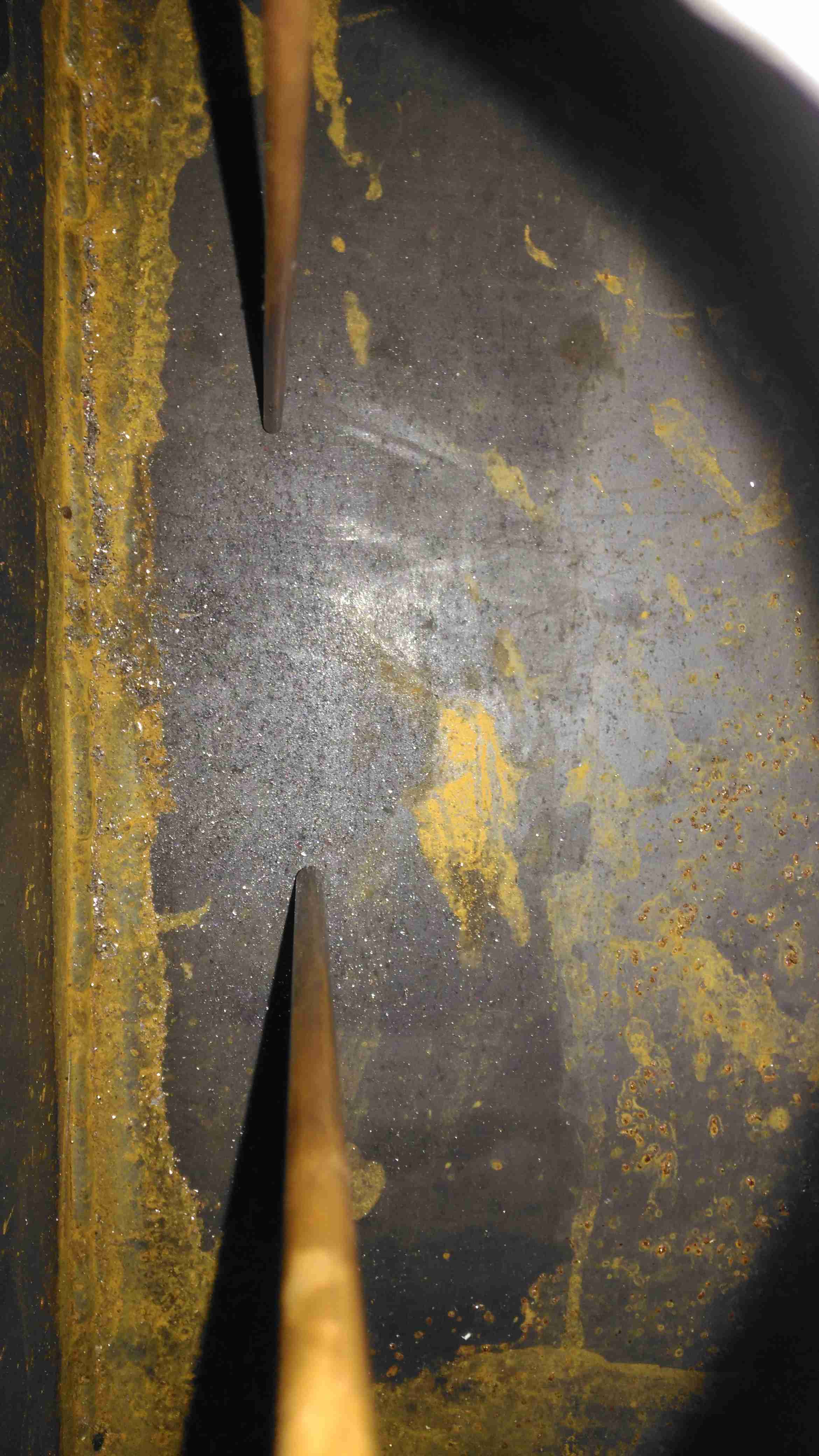
A quick view inside the tank through the level sender port shows the copper dip tubes for fuel supply to the heater, and an external fuel hose for my other fuel-powered camping gear. These tubes stop about 10mm from the bottom of the tank to stop any moisture or dirt from being drawn into the pumps.

Fuel Feeds & Level Sender Port

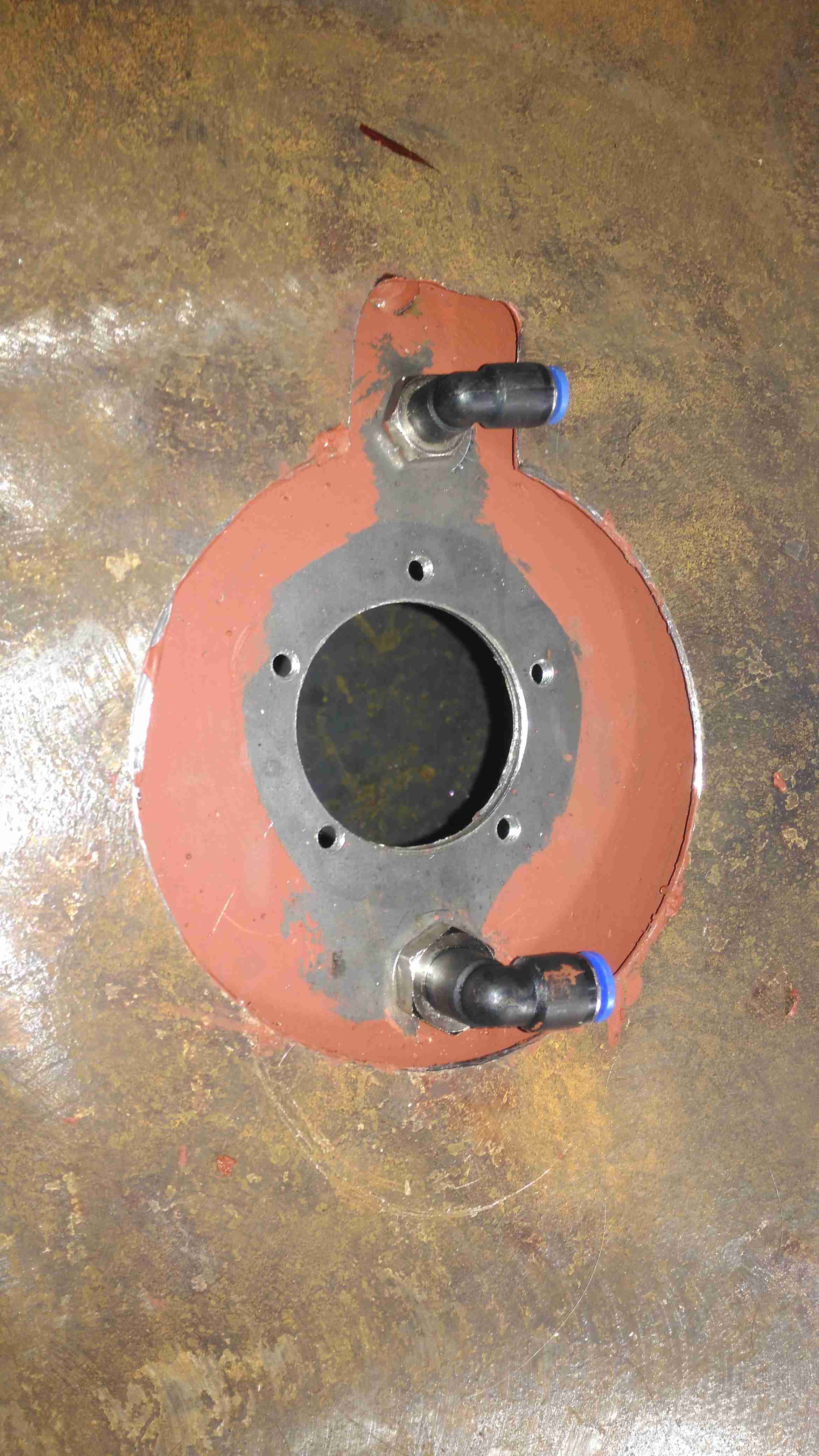
The top of the tank is drilled for the fuel fittings & the level sender and has already been painted here. The 1mm base plate has yet to be painted.

Level Sender Installed

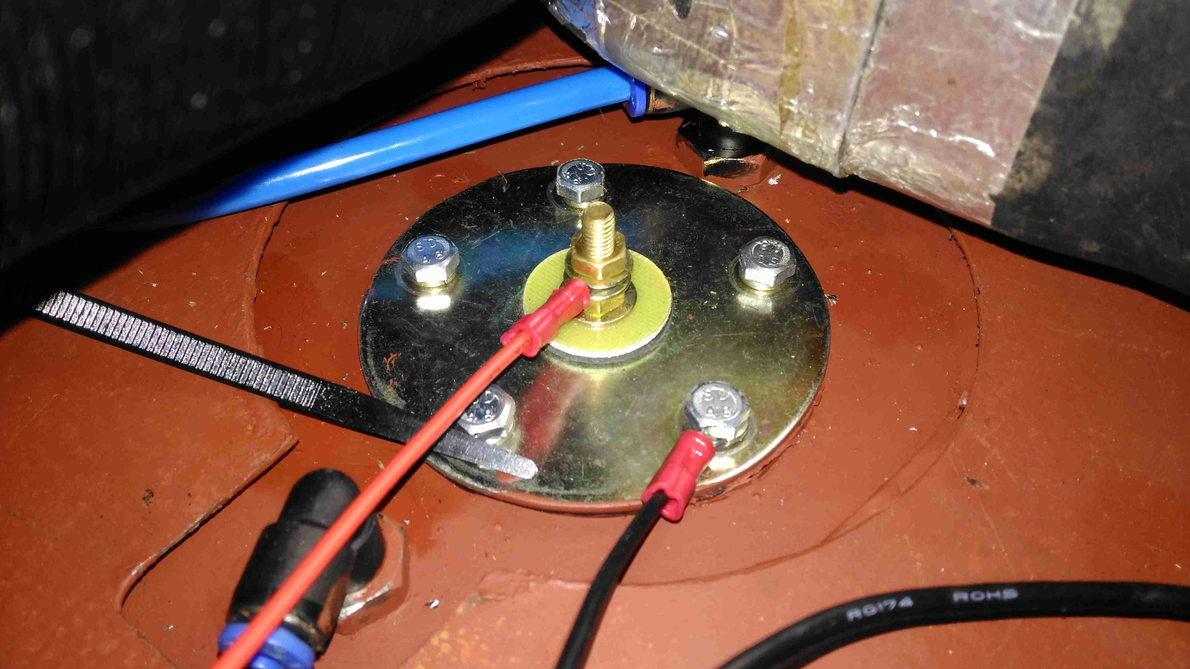
Touching up the paint & fitting the sender is the last job for this part. The mesh bottom of the trolley has been replaced by a 1mm steel sheet to support the other parts, mainly the heater. Fuel lines are run in polyurethane tubing to the fuel pumps.

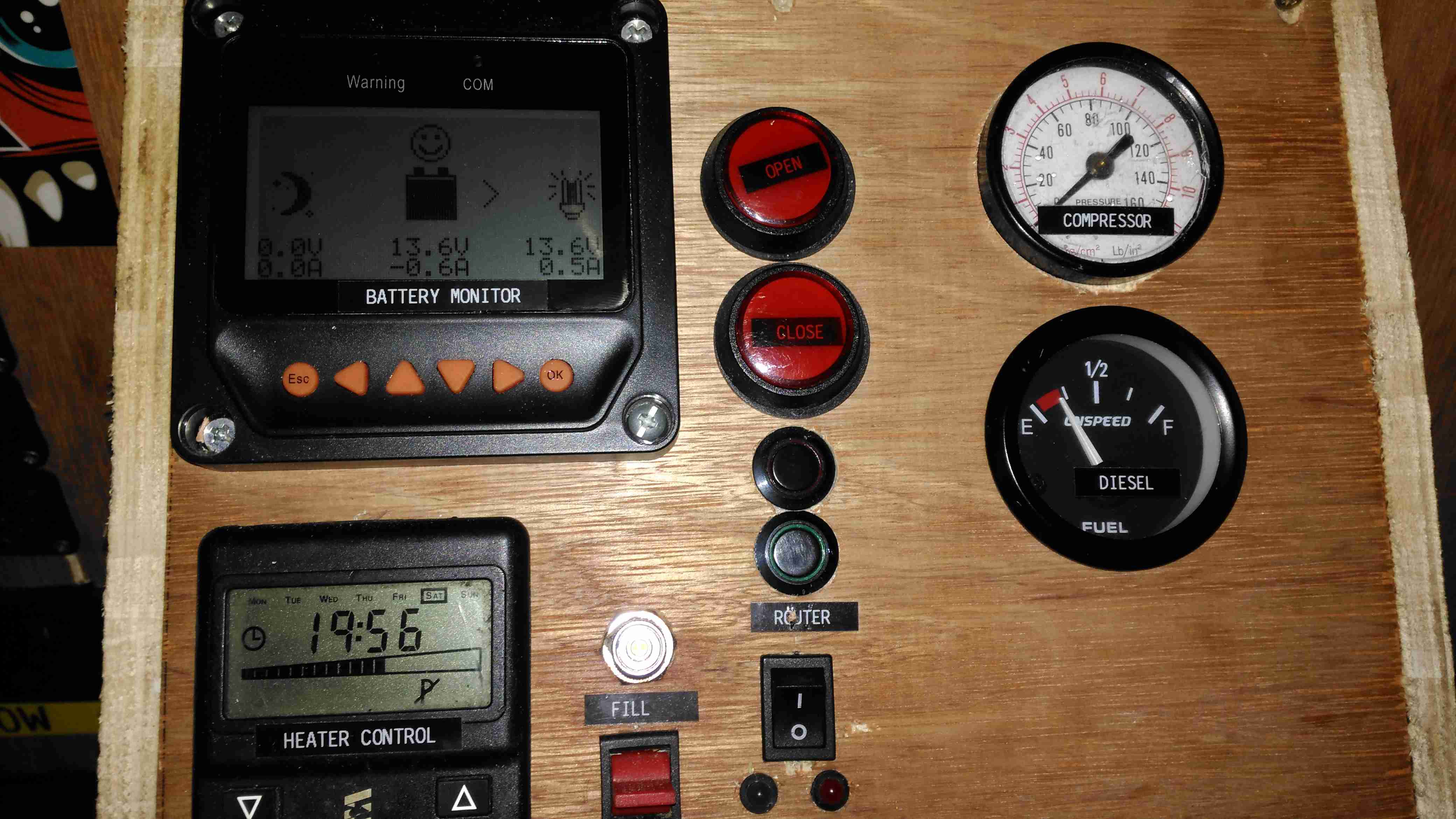
All the instruments & controls are on a single panel, with the Eberspacher thermostat, external fuelling port & pump switch, inverter control, the solar controller monitor panel, cover buttons, router controls, compressed air & fuel gauges.

Panel Wiring
Panel Wiring

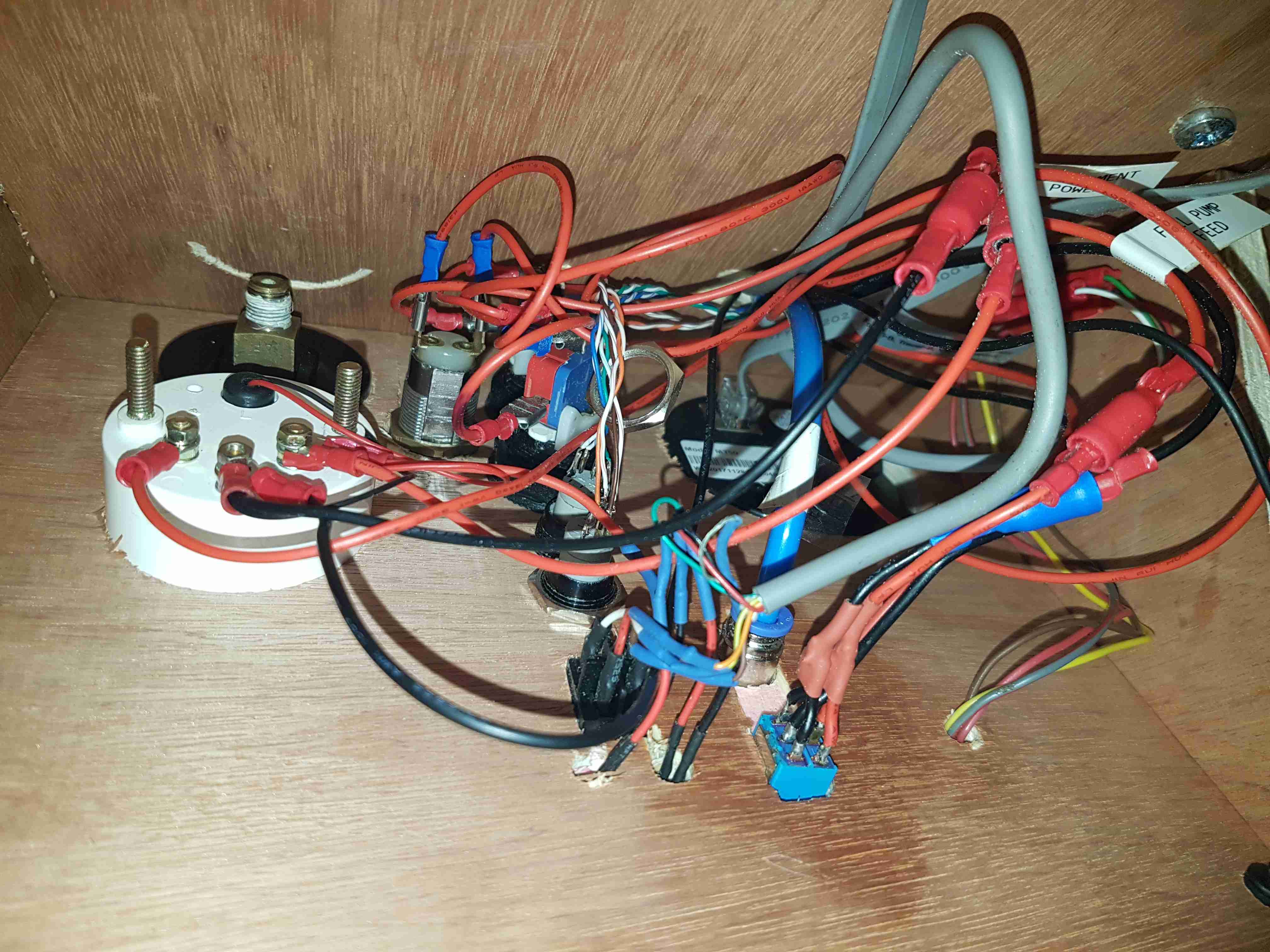
As is usual behind instrument panels, there’s a rat’s nest of wiring. There’s still the pressure gauge to connect up for the compressed air system, and the nut on one of the router buttons is such a tight fit I’ve not managed to get it into place yet.

Eberspacher Fuel Pump

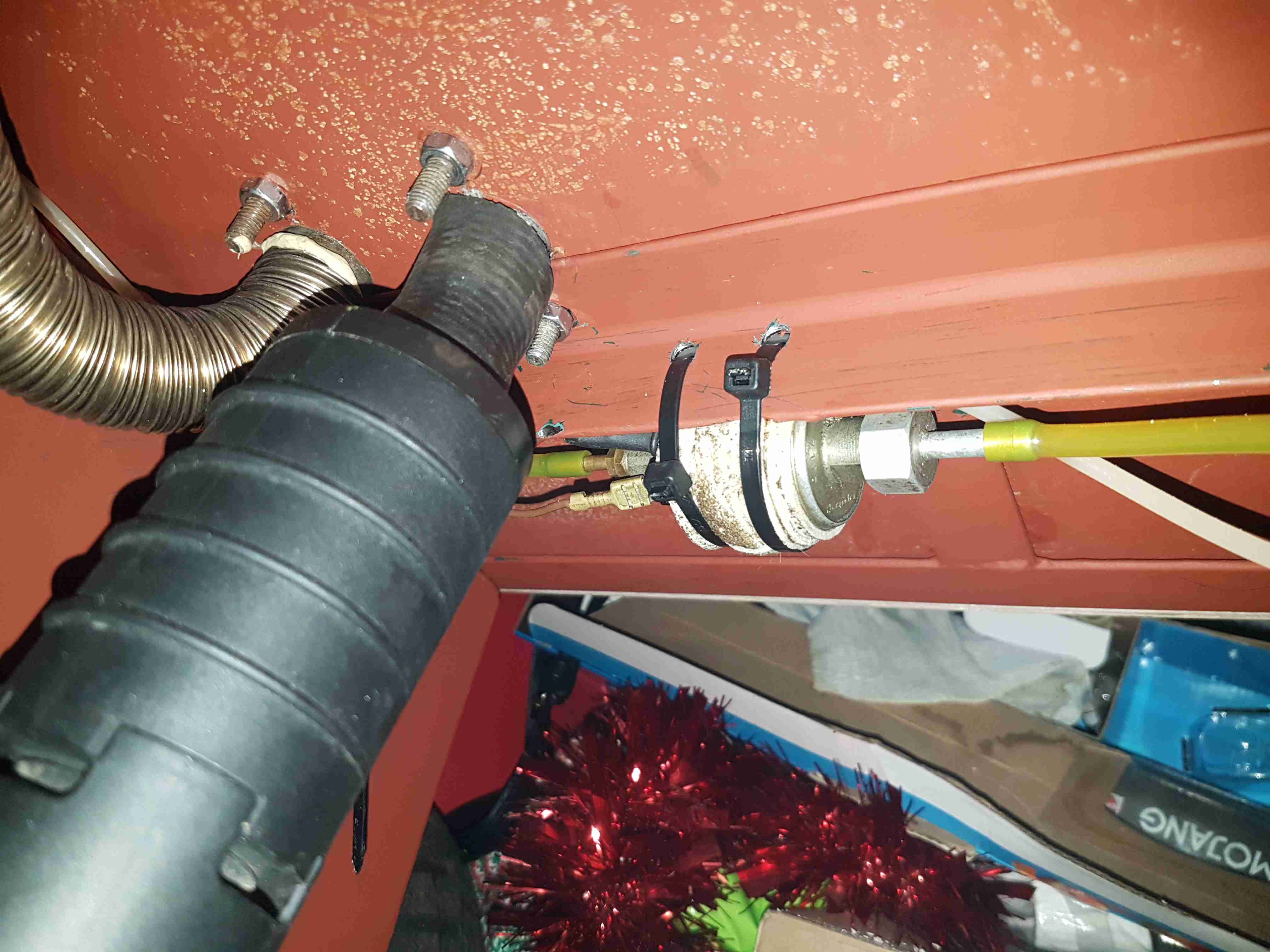
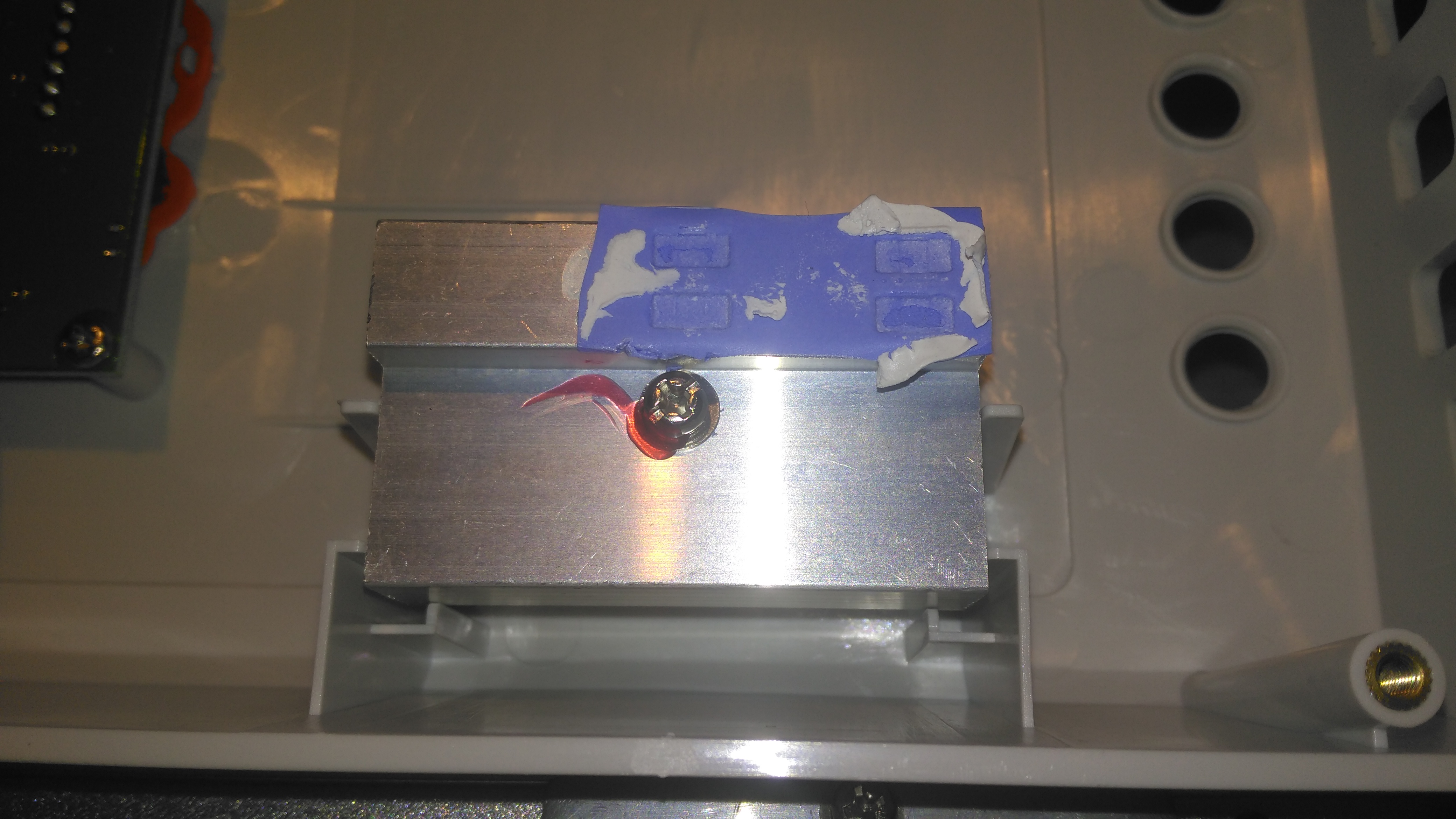
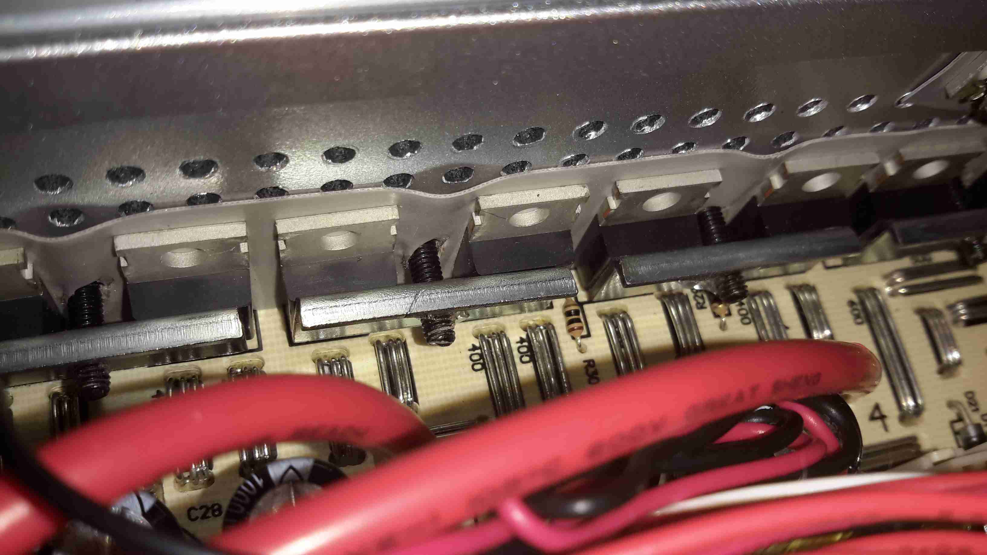
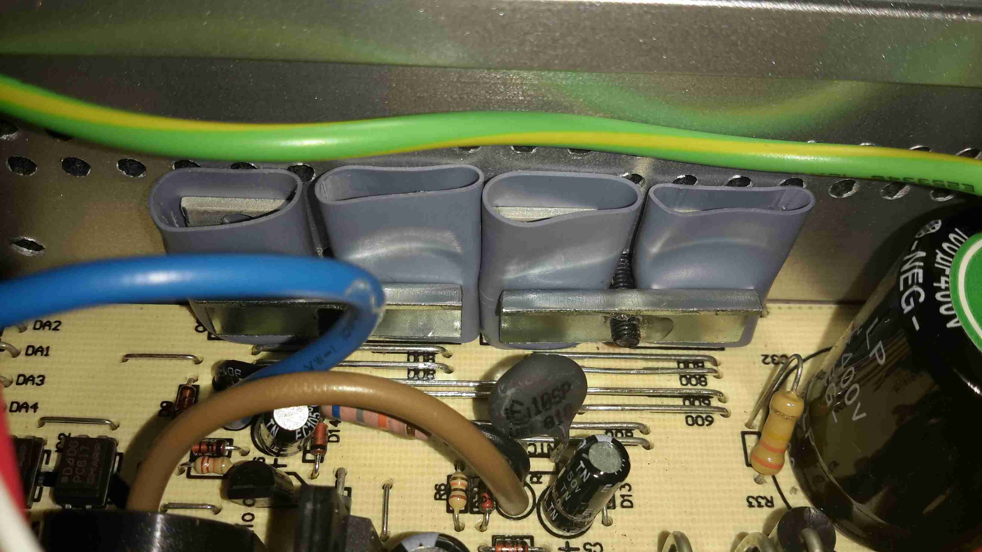
The support components for the Eberspacher heater are mounted underneath the baseplate, with the fuel dosing pump secured to a rail with a pair of cable ties, and some foam tape around to isolate the constant clicking noise these pumps create in operation. The large black cylinder is the combustion air intake silencer, with the stainless steel exhaust pipe to the left of that. Silencing these heaters is essential – they sound like a jet engine without anything to deaden the noise. Most of this is generated from the side-channel blower used in the burner.

Eberspacher Exhaust
Eberspacher Exhaust

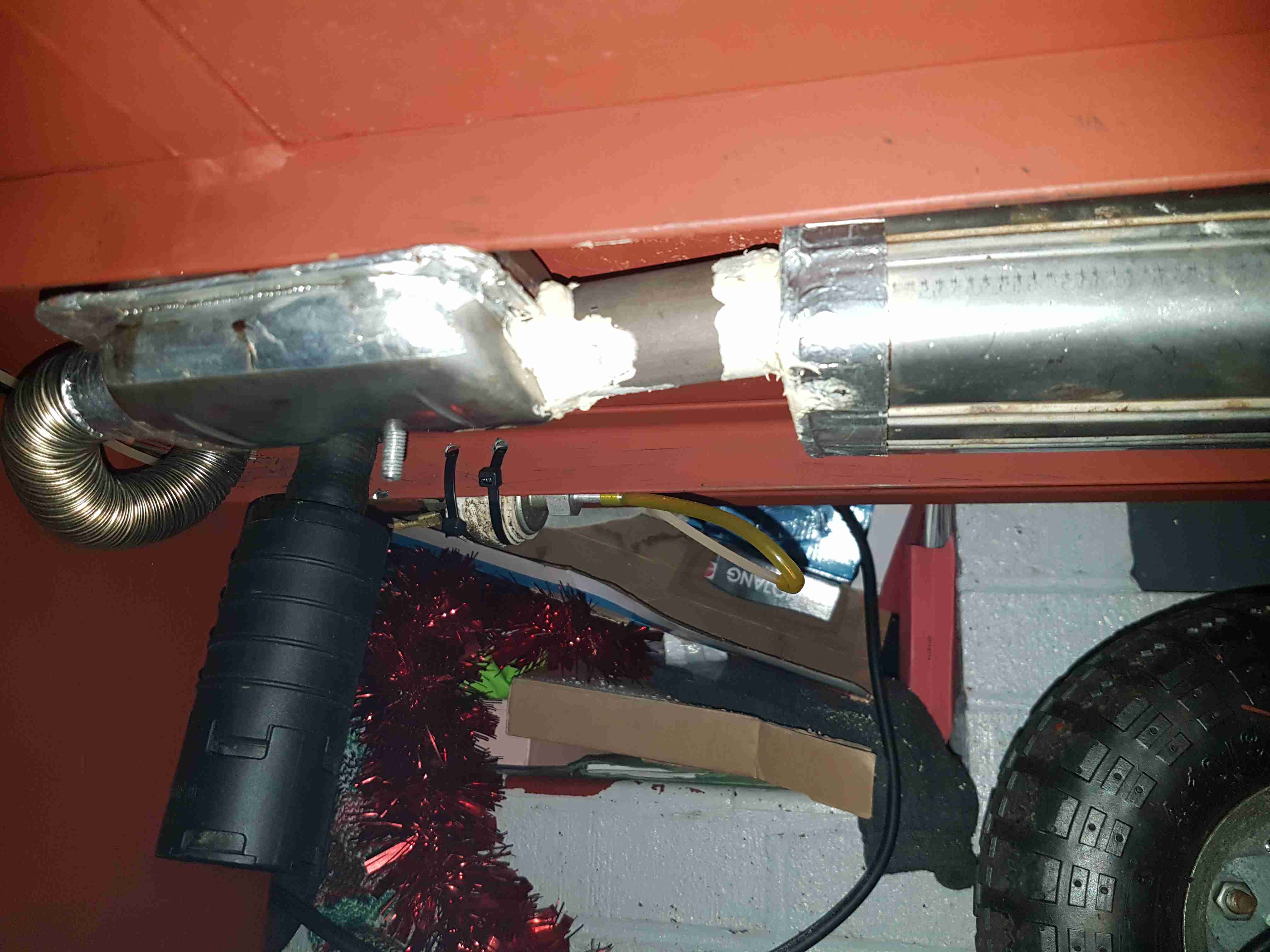
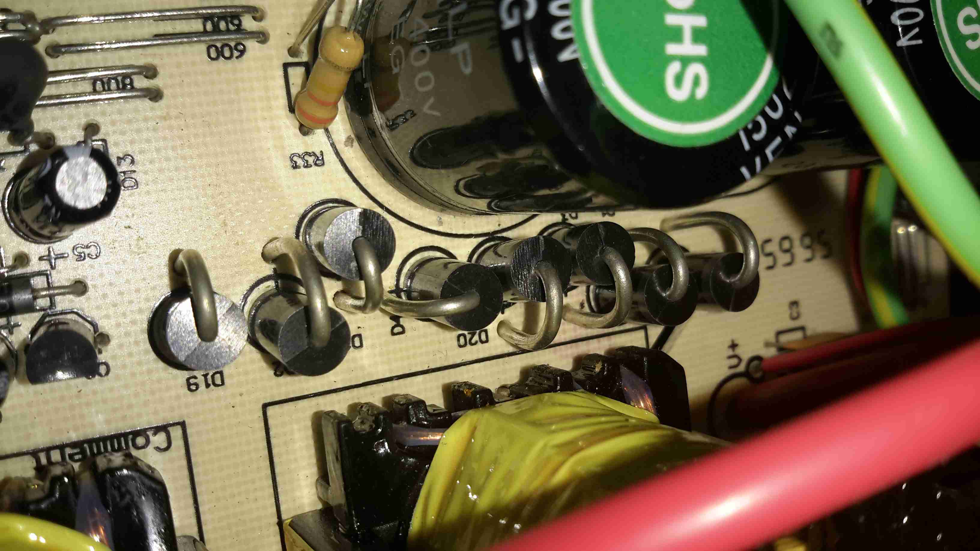
Bolted to the underside are a pair of exhaust silencers, one is an Eberspacher brand, the other is Webasto, since the latter type are better at reducing the exhaust noise. Connections are sealed with commerical exhaust assembly paste, the usual clamps supplied do not do a good enough job of stopping exhaust leaks.

Next update to come when I get the parts in for the air compressor system.

Posted on 3 Comments

103RS GPS Tracker Teardown

Rewire Security 103RS Tracker

I thought it was time to add a bit of security to the gear I take camping, so this GPS tracker unit was sourced from eBay. This is a Rewire Security 103RS, a slightly customised version of the common Chinese TK103 GPS tracker.

Input Connections
Input Connections

The small module has all it’s power connections on one end of the unit, on a Molex multi-way block. The white connector is for a piezo-shock sensor – this interfaces with the alarm functionality of the unit. There’s an indicator LED for both the GPS & GSM status, and a switch for the backup battery.

Antenna Connections
Antenna Connections

The other end has the antenna connections, microphone connection for the monitor function, along with the SIM & SD card slots.

PCB Top
PCB Top

Once the end panel is removed, the PCB just slides out of the aluminium extruded casing. It’s pretty heavily packed with components in here. A switching regulator deals with the 12v input from the vehicle battery, and is protected by a polyfuse on the right. The GSM module is hiding under the Li-Po backup cell, unfortunately the sticky pad used to secure this wouldn’t come off without damaging something. The pigtails for both the GPS & GSM antennas are permanently soldered to the board here.

PCB Bottom
PCB Bottom

The bottom of the PCB has the GPS module, and mainly input protection & bypassing components. There is a FNK4421 Dual P-Channel MOSFET here as well, probably used for switching the external relay or alarm siren. The SIM socket for the GSM modem is located here in the corner.

Posted on 5 Comments

EpEver Tracer 4210A MPPT Solar Charge Controller Teardown

Tracer 4210A MPPT Solar Controller

Here’s the solar charge controller to go with the MT50 from the last post. This is the 40A version of the EpEver Tracer A series, the 4210A. This unit is large, and very heavy. Most of this weight comes from the enormous heatsink which doubles as the mounting plate for all the other components, and the large inductors that are going to be required for the DC-DC conversion that MPPT requires.

Front Panel
Front Panel

The front panel has a basic LCD, which shows various stats, such as PV Volts & Amps, and battery bank Volts & Amps. The pair of buttons are used to navigate the basic menu to configure some options, along with switching the load terminals ON/OFF.

Specifications
Specifications

There’s a specs label on the top, with a slight difference here vs the manual, which states the max. PV volts as 92v.

Main PCB Overview
Main PCB Overview

Removing 4 machine screws from the bottom of the unit allows the top to come off. Like the MT50 remote panel, this unit also has moulded-in brass thread inserts in the plastic parts. The PCB in here is heavily comformal coated, which stops me from reading the laser-etched numbers on the semiconductor devices, so there will be few details there.

Main PCB Lower
Main PCB Lower

Here’s the bottom section of the main PCB, with the enormous screw terminals, which will easily take cables up to about 16mm². The RJ-45 jack which hosts the unit’s RS-485 bus is to the right, and a smaller 2-pin connector on the left sorts out the battery temperature sensor.
The DC output MOSFET switches are hiding just behind the right-hand terminals, there’s a pair of them in this unit to handle the output current. Some beefy diodes polarity-protect both the battery & PV inputs.

Board Centre
Board Centre

Moving up the board shows two 35A automotive blade fuses soldered into the board – these would be a real pain to replace if they ever blew, however with the electronic load current protection built into this unit, it’s an unlikely situation, unless something went hideously wrong. The main switching devices for the DC-DC converter are hidden – they’re clamped to the heatsink with the bars at right angles in the photo, I’m not going to dig any deeper into this just for those though – they’re just TO220 devices.
Under a load of thermal gunk on the right are 4 current shunt resistors, and the amplifiers for reading their values. These 1206-size SMD resistors looked a bit small for the power rating to me, but they’re heatsinked in operation to a small heatsink mounted in the top cover.

Board Upper
Board Upper

The upper section of the PCB hosts the main microcontroller, and the connections over to the front panel LCD & buttons. Couldn’t really get much info from these chips, due to the conformal coating.

Toroidal Inductors
Toroidal Inductors

Right at the top of the unit are these toroidal inductors, potted into aluminium housings. The copper windings of these is very heavy – at least 2.5mm². They’re electrically in parallel, the 20A version would only have a single inductor.

Current Shunt Heatsink

This small heatsink sits inside the top cover, and provides some cooling to the current shunts.

Display Board
Display Board

Not much to say for the display board, there’s going to be nothing here apart from an I²C LCD driver & the pair of front panel buttons, so I won’t bother removing this from the case.

Posted on Leave a comment

Tenda S105 5-Port 10/100 Ethernet Switch

Top
Top

Here’s a tiny ethernet switch from the great fle market that is eBay – the Tenda S105. This unit has 5 ports, but only supports 10/100M. Still, for something so small it’s not bad.

Bottom
Bottom

Not much on the bottom, there’s a pair of screw hooks for mounting this to a surface.

Ports
Ports

The 5 ports on the front actually have the pins for the unused pairs of the ethernet cables removed – saving every penny here.

PCB Top
PCB Top

The casing just unclips, revealing the small PCB. Nothing much on the top, just the connectors, isolating transformers & the crystal for the switch IC.

PCB Bottom
PCB Bottom

The bottom of the PCB is a little more busy, mainly with decoupling components. There’s a 3.3v linear regulator to step down the 5v input for the switch IC.

Switch IC
Switch IC

The IC doing all the data switching is an IP175G 5-Port 10/100 Switch from IC+ Corp. No datasheet available for this, but it’s going to be a bog-standard switch.

Posted on Leave a comment

Anker PowerPort Speed 5 12v DC Conversion

A few months ago I did a teardown on this Anker PowerPort Speed 5 USB charger, but I didn’t get round to detailing the conversion to 12v I had to do, so I’ll get to that now I’ve got a couple more to convert over.

Power Module
Power Module

Here’s the internals of the Anker charger once I’ve removed the casing – which like many things these days, is glued together. (Joints can be cracked with a screwdriver handle without damaging the case). There’s lots of heatsinking in here to cool the primary side switching devices & the pot core transformers, so this is the first thing to get removed.

Heatsink Removed
Heatsink Removed

Once the heatsink has been removed, the pot core transformers are visible, wrapped in yellow tape. There’s some more heatsink pads & thermal grease here, to conduct heat better. The transformers, primary side switching components & input filter capacitor have to go.

Primary Side Components Removed

Here’s the PCB once all the now redundant mains conversion components have been deleted. I’ve left the input filtering & bridge rectifier in place, as this solves the issue of the figure-8 cable on the input being reversible, polarity of the input doesn’t matter with the bridge. I’ve removed the main filter capacitor to make enough room for the DC-DC converters to be fitted.

Tails Installed
Tails Installed

Installing the tails to connect everything together is the next step, this charger requires two power supplies – the QC3 circuits need 14.4v to supply the multi-voltage modules, the remaining 3 standard ports require 5v. The DC input tails are soldered into place where the main filter capacitor was, while the outputs are fitted to the spot the transformer secondary windings ended up. I’ve left the factory Schottky rectifiers in place on the secondary side to make things a little more simple, the output voltages of both the DC-DC converters does need to be increased slightly to compensate for the diode drops though. I’ve also bypassed the mains input fuse, as at 12v the input current is going to be substantially higher than when used on mains voltage.

DC-DC Converters Installed

With a squeeze both the boost converter & the buck converter fit into place on the PCB.

Posted on 1 Comment

32A Bench PSU Build

Load Test

Since I’ve discovered some nice high power PSUs in the form of Playstation 3 PSUs, it’s time to get a new Bench PSU Build underway!

Specifications
Specifications

I’ve gone for the APS-227 version as it’s got the 32A rail. This makes things slightly beefier overall, as the loading will never be anywhere close to 100% for long, more headroom on the specs is the result.

Desktop Instrument Case

The case I’ve chosen for this is an ABS desktop instrument case from eBay, the TE554 200x175x70mm. The ABS is easy to cut the holes for all the through-panel gear, along with being sturdy enough. Aluminium front & back panels would be a nice addition for a better look.

PSU Mounted
PSU Mounted

The PSU board is removed from it’s factory casing & installed on the bottom shell half, unfortunately the moulded-in posts didn’t match the screw hole locations so I had to mount some brass standoffs separately. The AC input is also fitted here, I’ve used a common-mode filter to test things (this won’t be staying, as it fouls one of the case screw holes). The 40A rated DC output cable is soldered directly to the PCB traces, as there’s no room under the board to fit the factory DC power connector. (This is the biggest case I could find on eBay, and things are still a little tight). Some minor modifications were required to get the PCB to fit correctly.

Output Terminals & Adjuster

I decided to add some limited voltage adjustment capability to the front panel, I had a 100Ω Vishay Spectrol Precision 10-turn potentiometer in my parts bin, from a project long since gone that just about fits between the panel & the output rectifier heatsink. The trimpot I added when I first posted about these PSUs is now used to set the upper voltage limit of 15 volts. (The output electrolytics are 16v rated, and are in an awkward place to get at to change for higher voltage parts). The binding posts are rated to 30A, and were also left over from a previous project.

Vishay Spectrol 10-Turn


Addon Regulator Components

This front panel potentiometer is electrically in series with the trimpot glued to the top of the auxiliary transformer, see above for a simple schematic of the added components. In this PSU, reducing the total resistance in the regulator circuit increases the voltage, so make sure the potentiometer is wired correctly for this!
After some experimentation, a 500Ω 10-turn potentiometer would be a better match, with a 750Ω resistor in parallel to give a total resistance range on the front panel pot of 300Ω. This will give a lower minimum voltage limit of about 12.00v to make lead-acid battery charging easier.
I’ve had to make a minor modification to the output rectifier heatsink to get this pot to fit in the available space, but nothing big enough to stop the heatsink working correctly.

Terminal Posts
Terminal Posts

Here I’ve got the binding posts mounted, however the studs are a little too long. Once the wiring is installed these will be trimmed back to clear both the case screw path & the heatsink. (The heatsink isn’t a part of the power path anyway, so it’s isolated).

Power Meter Control Board & Fan

To keep the output rectifier MOSFETs cool, there’s a fan mounted in the upper shell just above their location, this case has vents in the bottom already moulded in for the air to exit. The fan is operated with the DC output contactor, only running when the main DC is switched on. This keeps the noise to a minimum when the supply doesn’t require cooling. The panel meter control board is also mounted up here, in the only empty space available. The panel meter module itself is a VAC-1030A from MingHe.

Meter Power Board
Meter Power Board

The measurement shunt & main power contactor for the DC output is on another board, here mounted on the left side of the case. The measurement shunt is a low-cost one in this module, I doubt it’s made of the usual materials of Manganin or Constantan, this is confirmed by my meansurements as when the shunt heats up from high-power use, the readings drift by about 100mA. The original terminal blocks this module arrived with have been removed & the DC cables soldered directly to the PCB, to keep the number of high-current junctions to a minimum. This should ensure the lowest possible losses from resistive heating.

Meter Panel Module
Meter Panel Module

The panel meter module iself is powered from the 5v standby rail of the Sony PSU, instead of the 12v rail. This allows me to keep the meter on while the main 12v output is switched off.

PSU Internals
PSU Internals

here’s the supply with everything fitted to the lower shell – it’s a tight fit! A standard IEC connector has been fitted into the back panel for the mains input, giving much more clearance for the AC side of things.

Inside View
Inside View

With the top shell in place, a look through the panel cutout for the meter LCD shows the rather tight fit of all the meter components. There’s about 25mm of clearance above the top of the PSU board, giving plenty of room for the 40mm cooling fan to circulate air around.

Load Test
Load Test

Here’s the finished supply under a full load test – it’s charging a 200Ah deep cycle battery. The meter offers many protection modes, so I’ve set the current limit at 30A – preventing Sony’s built in over current protection on the PSU tripping with this function is a bonus, as the supply takes a good 90 seconds to recover afterwards. I’ll go into the many modes & features of this meter in another post.

Posted on Leave a comment

IC Decap – TDA3606 Multi Regulator With Battery Sense

This is a chip aimed at the automotive market – this is a low power voltage regulator for supplying power to microcontrollers, for instance in a CD player.

TDA3606 Die
TDA3606 Die

The TDA3606 is a voltage regulator intended to supply a microprocessor (e.g. in car radio applications). Because of low voltage operation of the application, a low-voltage drop regulator is used in the TDA3606. This regulator will switch on when the supply voltage exceeds 7.5 V for the first time and will switch off again when the output voltage of the regulator drops below 2.4 V. When the regulator is switched on, the RES1  and RES2 outputs (RES2 can only be HIGH when RES1 is HIGH) will go HIGH after a fixed delay time (fixed by an external delay capacitor) to generate a reset to the microprocessor. RES1 will go HIGH by an internal pull-up resistor of 4.7 kΩ, and is used to initialize the microprocessor. RES2 is used to indicate that the regulator output voltage is within its voltage range. This start-up feature is built-in to secure a smooth start-up of the microprocessor at first connection, without uncontrolled switching of the regulator during the start-up sequence. All output pins are fully protected. The regulator is protected against load dump and short-circuit (foldback
current protection). Interfacing with the microprocessor can be accomplished by means of a battery Schmitt-trigger and output buffer (simple full/semi on/off logic applications). The battery output will go HIGH when the battery input voltage exceeds the HIGH threshold level.

Posted on 2 Comments

Ferguson A10RWH Portable Colour TV Teardown

Back Removed
Back Removed

Here’s the other TV that was picked up from the local water point having been put of to be recycled. This one is much newer than the Thorn TV, a 10″ colour version from Ferguson.

RCA 27GDC85X CRT
RCA 27GDC85X CRT

The colour CRT used is an RCA branded one, 27GDC85X.

Power Inputs
Power Inputs

Like the other TV, this one is dual voltage input, mains 240v & 12v battery. This TV is a factory conversion of a standard 240v AC chassis though.

HV PSU
HV PSU

The 12v power first goes into this board, which looked suspiciously like an inverter. Measuring on the output pins confirmed I was right, this addon board generates a 330v DC supply under a load, but it’s not regulated at all, under no load the output voltage shoots up to nearly 600v!

Live Chassis
Live Chassis

I’ve not seen one of these labels on a TV for many years, when back in the very old TV sets the steel chassis would be used to supply power to parts of the circuitry, to save on copper. Although it doesn’t have a metal chassis to actually become live, so I’m not sure why it’s here.

Main PCB
Main PCB

The main PCB is much more integrated in this newer TV, from the mid 90’s, everything is pretty much taken care of by silicon by this point.

Main Microcontroller

This Toshiba µC takes care of channel switching & displaying information on the CRT. The tuner in this TV is electronically controlled.

PAL Signal Processor

The video signal is handled by this Mitsubishi IC, which is a PAL Signal Processor, this does Video IF, Audio IF, Chroma, & generates the deflection oscillators & waveforms to drive the yoke.

CRT Adjustments
CRT Adjustments

There are some adjustments on the CRT neck board for RGB drive levels & cutoff levels. This board also had the final video amplifiers onboard, which drive the CRT cathodes.

Posted on Leave a comment

Behringer DEQ2496 Mastering Processor

Bootscreen
Bootscreen

I was recently given this unit, along with another Behringer sound processor to repair, as the units were both displaying booting problems. This first one is a rather swish Mastering Processor, which has many features I’ll leave to Behringer to explain 😉

Input Board & Relays

All the inputs are on the back of this 19″ rackmount bit of kit, nothing much on this PCB other than the connectors & a couple of switching relays.

Main Processor PCB
Main Processor PCB

All the magic is done on the main processor PCB, which is host to 3 Analog Devices DSP processors:

ADSP-BF531 BlackFin DSP. This one is probably handling most of the audio processing, as it’s the most powerful DSP onboard at 600Mhz. There’s a ROM on board above this for the firmware & a single RAM chip. On the right are a pair of ADSP-21065  DSP processors at a lower clock rate of 66MHz. To the left is some glue logic to interface the user controls & dot-matrix LCD.

PSU Module
PSU Module

The PSU in this unit is a pretty standard looking SMPS, with some extra noise filtering & shielding. The main transformer is underneath the mu-metal shield in the centre of the board.

Posted on 12 Comments

Panasonic NV-M5 VHS Camcorder Teardown

Overview

Panasonic NV-M5 Camera

Time foe some more retro tech! This is a 1980’s vintage CCD-based VHS camcorder from Panasonic, the NV-M5. There are a lot of parts to one of these (unlike modern cameras), so I’ll split this post into several sections to make things easier to read (and easier to keep track of what I’m talking about :)).

Left Side
Left Side

The left side of the camera holds the autofocus, white balance, shutter speed & date controls.

Left Side Controls
Left Side Controls
Lens Adjustments
Lens Adjustments

The lens is fully adjustable, with either manual or motorized automatic control.

Rear Panel
Rear Panel

The back panel has the battery slot, a very strange looking DC input connector, remote control connector & the earphone jack.

Top Controls
Top Controls

The top panel of the camera holds the main power controls, manual tape tracking & the tape transport control panel.

Viewfinder
Viewfinder

The viewfinder is mounted on a swivel mount. There’s a CRT based composite monitor in here. Hack ahoy!

Camera Section

Process Board Assembly

Here’s the camera section of the camcorder, and is totally packed with electronics! There’s at least half a dozen separate boards in here, all fitted together around the optics tube assembly.

AWB PCB
AWB PCB

On the top of the assembly is the Automatic White Balance PCB. Many adjustments here to get everything set right. Not much on the other side of this board other than a bunch of Op-Amps. The iris stepper motor is fitted in a milled opening in the PCB, this connects to one of the other PCBs in the camera module.

AWB Sensor
AWB Sensor

Here’s the AWB sensor, mounted next to the lens. I’m not all to certain how this works, but the service manual has the pinout, and there are outputs for all the colour channels, RGB. So it’s probably a trio of photodiodes with filters.

Focus & Zoom Motors
Focus & Zoom Motors

Focus & Zoom are controlled with a pair of DC gear motors. The manual operation is feasible through the use of slip clutches in the final drive pinion onto the lens barrel.

Process Board
Process Board

The main camera section process board is above. This board does all the signal processing for the CCD, has the bias voltage supplies and houses the control sections for the motorized parts of the optics assembly. There are quite a few dipped Tantalum capacitors on pigtails, instead of being directly board mounted. This was probably done due to space requirements on the PCB itself.2016-08-20_13-40-11_000357

Under the steel shield on this board is some of the main signal processing for the CCD.

Optics Assembly
Optics Assembly

The back of the optics tube is a heavy casting, to supress vibration. This will be more clear later on.

Position Sensor Flex

The position of the lens elements is determined by reflective strips on the barrel & sensors on this flex PCB.

Sub Process Board
Sub Process Board

There’s another small board tucked into the side of the tube, this hooks into the process PCB.

Process Delay Line
Process Delay Line

According to the schematic, there’s nothing much on this board, just a delay line & a few transistors.

Piezo Focus Disc
Piezo Focus Disc

Here’s the reason for the heavy alloy casing at the CCD mounting end of the optics: the fine focus adjustment is done with a piezoelectric disc, the entire CCD assembly is mounted to this board. Applying voltage to the electrodes moves the assembly slightly to alter the position of the CCD. The blue glass in the centre of the unit is the IR filter.

IR Relective Sensors

The barrel position sensors are these IR-reflective type.

Iris Assembly
Iris Assembly

The iris is mounted just before the CCD, this is controlled with a galvanometer-type device with position sensors incorporated.

Iris Opening
Iris Opening

Pushing on the operating lever with the end of my screwdriver opens the leaves of the iris against the return spring.

Tape Transport & Main Control

Main Control Board
Main Control Board

Tucked into the side of the main body of the unit is the main system control board. This PCB houses all the vital functions of the camera: Power Supply, Servo Control, Colour Control,Video Amplifiers, etc.

Tape Drum
Tape Drum

Here’s the main tape transport mechanism, this is made of steel & aluminium stampings for structural support. The drum used in this transport is noticeably smaller than a standard VHS drum, the tape is wrapped around more of the drum surface to compensate.

Tape Transport
Tape Transport

The VHS tape sits in this carriage & the spools drive the supply & take up reels in the cartridge.

Main Control PCB
Main Control PCB

Here’s the component side of the main control PCB. This one is very densely packed with parts, I wouldn’t like to try & troubleshoot something like this!

Main PCB Left
Main PCB Left

The left side has the video head amp at the top, a Panasonic AN3311K 4-head video amp. Below that is video processing, the blue components are the analogue delay lines. There are a couple of hybrid flat-flex PCBs tucked in between with a couple of ICs & many passives. These hybrids handle the luma & chroma signals.
Top left is the capstan motor driver a Rohm BA6430S. The transport motors are all 3-phase brushless, with exception of the loading motor, which is a brushed DC type.

Delay Line
Delay Line

Here’s what is inside the delay lines for the analogue video circuits. The plastic casing holds a felt liner, inside which is the delay line itself.

Internal Glass
Internal Glass

The delay is created by sending an acoustic signal through the quartz crystal inside the device by a piezoelectric transducer, bouncing it off the walls of the crystal before returning it to a similar transducer.

Main PCB Centre
Main PCB Centre

Here’s the centre of the board, the strange crystal at bottom centre is the clock crystal for the head drum servo. Why it has 3 pins I’m not sure, only the two pins to the crystal inside are shown connected on the schematic. Maybe grounding the case?
The main servo controls for the head drum & the capstan motor are top centre, these get a control signal from the tape to lock the speed of the relative components.

Main PCB Right
Main PCB Right

Here’s the right hand side. The main power supply circuitry is at top right, with a large can containing 4 switching inductors & a ferrite pot core transformer. All these converters are controlled by a single BA6149 6-channel DC-DC converter controller IC via a ULN2003 transistor array.
The ceramic hybrid board next to the PSU has 7 switch transistors for driving various indicator LEDs.
The large tabbed IC bottom centre is the loading motor drive, an IC from Mitsubishi, the M54543. This has bidirectional DC control of the motor & built in braking functions. The large quad flat pack IC on the right is the MN1237A on-screen character generator, with the two clock crystals for the main microcontroller.

Erase Head
Erase Head

The full erase head has it’s power supply & oscillator on board, applying 9v to this board results in an AC signal to the head, which erases the old recording from the tape before the new recording is laid down by the flying heads on the drum.

Audio Control PCB
Audio Control PCB

The Audio & Control head is connected to this PCB, which handles both reading back audio from the tape & recording new audio tracks. The audio bias oscillator is on this board, & the onboard microphone feeds it’s signal here. The control head is fed directly through to the servo section of the main board.

Drum Motor
Drum Motor

The motor that drives the head drum is another DC brushless 3-phase type.

Hall Sensors
Hall Sensors

These 3 Hall sensors are used by the motor drive to determine the rotor position & time commutation accordingly.

Stator
Stator

The stator on this motor is of interesting construction, with no laminated core, the coils are moulded into the plastic holder. The tach sensor is on the side of the stator core. This senses a small magnet on the outside of the rotor to determine rotational speed. For PAL recordings, the drum rotates at 1500 RPM.

Motor Removed
Motor Removed

Not much under the stator other than the bearing housing & the feedthrough to the rotary transformer.

Head Disc
Head Disc

The heads are mounted onto the top disc of the drum, 4 heads in this recorder. The signals are transmitted to the rotating section through the ferrite rotary transformer on the bottom section.

Head Chip
Head Chip

The tiny winding of the ferrite video head can just about be seen on the end of the brass mounting.

Capstan Motor Components

The capstan motor is similar to the drum motor, only this one is flat. The rotor has a ferrite magnet, in this case it wasn’t glued in place, just held by it’s magnetic field.

Capstan Motor Stator

The PCB on this motor has a steel backing to complete the magnetic circuit, the coils for the 3 motor phases are simply glued in place. The Hall sensors on this motor are placed in the middle of the windings though.
Again there is a tach sensor on the edge of the board that communicates the speed back to the controller. This allows the servo to remain locked at constant speed.

Viewfinder

Viewfinder Assembly
Viewfinder Assembly

As usual with these cameras, this section is the CRT based viewfinder. These units take the composite signal from the camera to display the scene. This one has many more pins than the usual viewfinder. I’ll hack a manual input into this, but I’ll leave that for another post.

Viewfinder Circuits
Viewfinder Circuits

Being an older camera than the ones I’ve had before, this one is on a pair of PCBs, which are both single-sided.

Main Viewfinder Board

The main board has all the power components for driving the CRT & some of the adjustments. The main HV flyback transformer is on the right. This part creates both the final anode voltage for the tube & the focus/grid voltages.

Viewfinder Control PCB Top

The viewfinder control IC is on a separate daughter board in this camera, with two more controls.

Control IC
Control IC

The control IC is a Matsushita AN2510S, this has all the logic required to separate the sync pulses from the composite signal & generate an image on the CRT.

Viewfinder CRT Frame

The recording indicator LEDs are mounted in the frame of the CRT & appear above the image in the viewfinder.

Viewfinder CRT With Yoke

Here the CRT has been separated from the rest of the circuitry with just the deflection yoke still attached.

M01JPG5WB CRT
M01JPG5WB CRT

The electron gun in this viewfinder CRT is massive in comparison to the others that I have seen, and the neck of the tube is also much wider. These old tubes were very well manufactured.

Viewfinder Optics
Viewfinder Optics

A simple mirror & magnifying lens completes the viewfinder unit.

Posted on Leave a comment

MingHe D3806 Buck-Boost DC-DC Converter

DC-DC Converter
DC-DC Converter

Here’s a useful buck-boost DC-DC converter from eBay, this one will do 36v DC at 6A maximum output current. Voltage & current are selected on the push buttons, when the output is enabled either the output voltage or the output current can be displayed in real time.

Display PCB
Display PCB

Here’s the display PCB, which also has the STM32 microcontroller that does all the magic. There appears to be a serial link on the left side, I’ve not yet managed to get round to hooking it into a serial adaptor to see if there’s anything useful on it.

Display Drive & Microcontroller

The bottom of the board holds the micro & the display multiplexing glue logic.

Main PCB
Main PCB

Not much on the mainboard apart from the large switching inductors & power devices. There’s also a SMPS PWM controller, probably being controlled from the micro.

Posted on Leave a comment

eBay Flyback High Voltage PSU

Flyback PSU
Flyback PSU

I have found myself needing some more in the way of High Voltage supplies of late, with the acquisition of the new He-Ne laser tubes, so I went trawling eBay for something that would be suitable to run these tubes. (I currently only have a single He-Ne laser PSU brick, and they’re notoriously hard to find & rather expensive).
This supply is rated at 1kV-10kV output, at 35W power level. Unfortunately this supply isn’t capable of sustaining the discharge in a large He-Ne tube, the impedance of the supply is far too high. Still, it’s useful for other experiments.
The flyback-type transformer clearly isn’t a surplus device from CRT manufacture, as there are very few pins on the bottom, and none of them connect to the primary side. The primary is separately wound on the open leg of the ferrite core.

Drive Electronics
Drive Electronics

The drive electronics are pretty simple, there’s a controller IC (with the number scrubbed off – guessing it’s either a 556 dual timer or a SMPS controller), a pair of FDP8N50NZ MOSFETs driving the centre-tapped primary winding.
The drive MOSFETs aren’t anything special in this case: they’re rated at 500v 8A, 850mΩ on resistance. This high resistance does make them get rather hot even with no load on the output, so for high power use forced-air cooling from a fan would definitely be required.

Test Setup
Test Setup

Here’s the supply on test, I’ve got the scope probes connected to the gate resistors of the drive MOSFETs.

Waveforms
Waveforms

On the scope the primary switching waveforms can be seen. The FETs operate in push-pull mode, there’s a bit of a ring on the waveform, but they’re pretty nice square waves otherwise.

Arc
Arc

At maximum power on 12v input, about 25mm of gap is possible with an arc.

Posted on Leave a comment

Aspen Universal Condensate Pump

Universal Peristaltic Condensate Pump

Here’s another piece of commercial gear, from an industrial air conditioning unit. These pumps are used to drain the condensate from the evaporator unit, so water doesn’t end up raining down from the ceiling.

Pump Head
Pump Head

This is a peristaltic pump, with a silicone hose forming the pumping element.

Rear Panel
Rear Panel

The test switch & electrical connections are on the back, along with the data label.

Power & Sensor Socket

The electrical connections are all on a single 5-pin socket. Along with 240v AC mains, there are a pair of thermistors connected to the unit, which switch the pump on when a 5°C temperature difference across the evaporator coil is detected. When air is cooled, it’s capacity for moisture drops, so the water condenses out on the coil.

Roller Wheel
Roller Wheel

Here the front cover has been removed from the pump, showing the silicone tube & roller wheel. The wheel was originally Cadmium-plated, but exposure to the elements has oxidized this into highly toxic Cadmium Oxide.

Pump Rollers
Pump Rollers

Here you can see the rollers. These pinch the tube at the inlet, and the rotation carries a slug of liquid through the tube to the outlet side.

Pump Tube
Pump Tube

Here’s the tube itself, the main wearing part of the pump. This is replaceable as a spare part.

Motor & Gearbox
Motor & Gearbox

Inside the casing is a shaded-pole motor, connected to a large gearbox, to give the slow rotation for the pump head. The rated speed is 51RPM.

Control PCB
Control PCB

There’s not much to the control PCB. The large resistor forms a voltage dropper, to reduce the mains 240v to a more suitable level for the logic. There’s a TL062C Low-Power JFET Op-Amp & a CD4060BCM 14-stage binary ripple counter forming the logic. The set point is adjustable via the potentiometer.

Pump Triac
Pump Triac

The pump motor is switched via this Z7M SMD triac, not much switching power is needed here as the motor is only a very small shaded-pole type.

Posted on Leave a comment

Mini USB Soldering Iron

USB Soldering Iron
USB Soldering Iron

Here’s a novel little gadget, a USB powered soldering iron. The heating tip on these is very small & might be useful for very small SMD work. Bigger joints not so much, as it’s only rated at 8W. (Still breaks the USB standard of 2.5W from a single port).

These irons aren’t actually too bad to use, as long as the limitations in power are respected. Since nearly everything has a USB power port these days, it could make for a handy emergency soldering iron.

Heater Socket
Heater Socket

The heater & soldering bit are a single unit, not designed to be replaced separately. (I’ve not managed to find replacement elements, but at £3 for the entire iron, it would be pretty pointless).
Above is the socket where the heater plugs in, safely isolating the plastic body from any stray heat.

DC Input Jack
DC Input Jack

The DC input is a 3.5mm audio jack, a non-standard USB to 3.5mm jack cable is supplied. Such non-standard cables have the potential to damage equipment that isn’t expecting to see 5v on an audio input if it’s used incorrectly.

Touch Sensor & LED
Touch Sensor & LED

There isn’t actually a switch on this unit for power management, but a clever arrangement of a touch button & vibration switch. The vertical spring in the photo above makes contact with a steel ball bearing pressed into the plastic housing, forming the touch contact.

MOSFET
MOSFET

The large MOSFET here is switching the main heater current, the silver cylinder in front is the vibration switch, connected in parallel with the touch button.

PCB
PCB

The main controller is very simple. It’s a 555 timer configured in monostable mode. Below is a schematic showing the basic circuit.

555 Monostable
555 Monostable

Big Clive also did a teardown & review of this iron. Head over to YouTube to watch.

Posted on Leave a comment

De La Rue Coin Counting Machine Followup – PSU Oddness

I did a little more digging into the PSU circuitry of the small coin counting machine, and it’s even more strange than I thought!
The part I originally thought was a transformer on the PSU board is in fact a DC-DC converter module!

DC-DC Converter
DC-DC Converter

Here’s the device after desoldering it from the PCB. It turns out that instead of a transformer, it’s an inductor.

Hiding Control Electronics

Underneath is the controller electronics, with an COB controller & the switching transistors are under a protective covering of silicone.

Mains Transformer
Mains Transformer

Driving this whole lot of PSU randomness is the mains transformer, with a secondary voltage of 35v.

The only reason I can think of that the manufacturer went to this much expense with the power supply is stability – a coin counting machine that miscounts due to power supply surges, sags & spikes wouldn’t be very much use. It’s not likely I’ll see anything similar again, unless I manage to get hold of something like medical grade equipment.

Posted on 2 Comments

Maplin 600W “Modified Sine” Power Inverter

Maplin 600W Inverter

I’m no fan of power inverters. In my experience they’re horrifically inefficient, have power appetites that make engine starter motors look like electric toothbrushes & reduce the life expectancy of lead-acid batteries to no more than a few days.
However I have decided to do a little analysis on a cheapo “600W” model that Maplin Electronics sells.

Cover Removed
Cover Removed

After a serious amount of metallic abuse, the bottom cover eventually came off. The sheet of steel used to close the bottom of the aluminium extrusion was wedged into place with what was probably a 10 ton hydraulic press.
As can be seen from the PCB, there’s no massive 50Hz power transformer, but a pair of high frequency switching transformers. Obviously this is to lighten the weight & the cost of the magnetics, but it does nothing for the quality of the AC output waveform.

DC Input End
DC Input End

The 12v DC from the battery comes in on very heavy 8-gauge cables, this device is fused at 75A!

DC Fuses
DC Fuses

Here’s the fusing arrangement on the DC input stage, just 3 standard blade-type automotive fuses. Interestingly, these are very difficult to get at without a large hammer & some swearing, so I imagine if the user manages to blow these Maplin just expect the device to be thrown out.

Input DC-DC Switching MOSFETs

On the input side, the DC is switched into the pair of transformers to create a bipolar high voltage DC supply.

High Voltage Rectifiers

The large rectifier diodes on the outputs of the transformers feed into the 400v 100µF smoothing capacitors.
As mains AC is obviously a bipolar waveform, I’m guessing this is generating a ±150v DC supply.

Output MOSFETs
Output MOSFETs

After the high voltage is rectified & smoothed, it’s switched through 4 more MOSFETs on the other side of the PCB to create the main AC output.

The label states this is a modified-sine output, so I’d expect something on the scope that looks like this:

Inverter Waveforms
Inverter Waveforms

Modified-sine doesn’t look as bad as just a pure square output, but I suspect it’s a little hard on inductive loads & rectifiers.

However, after connecting the scope, here’s the actual waveform:

Actual Waveform
Actual Waveform

It’s horrific. It’s not even symmetrical. There isn’t even a true “neutral” either. The same waveform (in antiphase) is on the other mains socket terminal. This gives an RMS output voltage of 284v. Needless to say I didn’t try it under load, as I don’t possess anything I don’t mind destroying. (This is when incandescent lamps are *really* useful. Bloody EU ;)).

About the only thing that it’s accurate at reproducing is the 50Hz output, which it does pretty damn well.

System Microcontroller

As is usual these days, the whole system is controlled via a microcontroller.

Posted on Leave a comment

Netgear GS308 Gigabit Switch

Here’s a new addition to the network, mainly to replace the ancient Cisco Catalyst 3500 XL 100MB switch I’ve been using for many years, until I can find a decently priced second hand commercial gigabit switch.

Operational
Operational

Here’s the switch with some network connections on test. So far it’s very stable & draws minimum power. I’ve not yet attempted to run my core links (NAS) through yet, as I’ve not yet seen a consumer grade switch that can stand up to constant full load without crashing.

Internals
Internals

Here’s the switch with it’s lid popped. The magnetics can be seen at the back, next to the RJ-45 ports, the large IC in the centre is the main switching IC, with a heatsink bonded to the top. Very minimal design, with only a couple of switching regulators for power supply & not much else.

Power & EEPROM
Power & EEPROM

Here’s a closeup of some of the support components. There’s a 25MHz crystal providing a clock signal for the switch IC, just to the right of that is an EEPROM. I imagine this is storing the switch configuration & MAC address. Further right is one of the switching DC-DC converter ICs for power.

As a quick test, here’s 500GB of data being shifted through the switch, at quite an impressive rate. I’m clearly maxing out the bandwidth of the link here. Soon I will upgrade to a 10G Ethernet link between the NAS & main PC to get some more performance.

Test
Test
Posted on Leave a comment

5-Port HDMI Switch

HDMI Switch
HDMI Switch

Here’s another quick teardown, a cheap 5-port HDMI switch box. This is used to allow a single input on a monitor to be used by 5 different external HDMI devices, without having to mess about plugging things in.

Power & Remote
Power & Remote

Here’s the DC barrel jack & 3.5mm TRS jack for power & remote control. There’s a little IR decoder & remote that go with this for hands free switching.

PCB Top
PCB Top

Here’s the PCB out of it’s plastic housing. The main logic is a pair of PI3HDMI303 3:1 HDMI switches from Pericom Semiconductor. These are cascaded for the 5-ports, the first 3 input HDMI ports are switched through both ICs to reach the output.
These HDMI switch ICs are operated with TTL input pins, the combination of these pins held either high or low determines the input port that appears on the output.
There’s a button on the left for switching between inputs, with a row of 5 LED indicators.

PCB Bottom
PCB Bottom

Not much on the bottom side, a lot of passives & bypass capacitors. There’s a 3.3v LDO regulator on the left for supplying the main rail to the active switch ICs. The IC on the right doesn’t have any numbering at all, but I’m presuming it’s a microcontroller, dealing with the IR remote input & pushbutton inputs to switch the inputs.

Posted on Leave a comment

Maplin/Refrakta Torch Modification & Mode Removal

The multimode dimming/flashing modes on Chinese torches have irritated me for a while. If I buy a torch, it’s to illuminate something I’m doing, not to test if people around me have photosensitive epilepsy.

Looking at the PCB in the LED module of the torch, a couple of components are evident:

LED Driver PCB
LED Driver PCB

There’s not much to this driver, it’s simply resistive for LED protection (the 4 resistors in a row at the bottom of the board).
The components at the top are the multimode circuitry. The SOT-23 IC on the left is a CX2809 LED Driver, with several modes. The SOT-23 on the right is a MOSFET, for switching the actual LED itself. I couldn’t find a datasheet for the IC itself, but I did find a schematic that seems to match up with what’s on the board.

Schematic
Schematic

Here’s that schematic, the only thing that needs to be done to convert the torch to single mode ON/OFF at full brightness, is to bridge out that FET.

Components Desoldered

To help save the extra few mA the IC & associated circuitry will draw from the battery, I have removed all of the components involved in the multimode control. This leaves just the current limiting resistors for the LED itself.

Jumper Link
Jumper Link

The final part above, is to install a small link across the Drain & Source pads of the FET. Now the switch controls the LED directly with no silly electronics in between. A proper torch at last.

Posted on Leave a comment

Rigol DS1054Z DC Power Supply – Linear Post Regulation

Finally, here’s the last part of the Rigol 12v DC Power Supply project, the linear post regulation section to remove some of the ripple.

I have made a couple of layout adjustments since the last post about this part of the project – a little more filtering on the DC outputs. As usual the Eagle project files are at the bottom of the post for those who might find them useful.

Updated PCB
Updated PCB
Updated Schematic
Updated Schematic


Completed PCB
Completed PCB

Here’s the completed PCB, partially installed in the back of the scope. The missing regulator is the 5v one, since I already have a source of clean 5v from my original attempt at the supply, it’s not a problem not using a linear after the switcher. The filtering is the same on all channels, input from the switchers is on the right, outputs to the scope on the left.

PCB Bottom
PCB Bottom

Here’s the bottom of the PCB, with the common mode input chokes. The design of this board has allowed me to remove a couple of the switching modules as well, as I can use a single bipolar supply to run both sets of bipolar regulators on this board. This should help remove some of the noise also.

The ripple level has now dropped to lower than it was originally on the mains supply! Current draw at 13.8v DC is about 1.75A.

Scope Ripple
Scope Ripple

[download id=”5589″]

Posted on Leave a comment

Rigol DS1054Z 12v Power Supply Noise Filtering

Since I fitted my scope with a SMPS based 12v input supply, there has been a noise problem on very low volts/div settings, this noise isn’t present on the mains supply, so I can only think it’s coming from the switching frequencies of the various DC-DC modules I’ve used.

Scope Ripple
Scope Ripple

Because of this I’ve designed a linear post-regulation stage for the supply, to remove the RFI from the DC rails.
This board takes the outputs from the DC-DC converters, removes all the noise & outputs clean DC onto the mainboard of the scope.

As the scope internally uses regulation to get the voltages lower, I’ve found that I don’t have to match the outputs of the mains supply exactly, for the +/-17.5v rails, 12v is perfectly fine instead.

Scope Linear PSU
Scope Linear PSU

Here’s the PCB layout, with the 6  common mode filters on the input (left), linear regulator ICs in the centre & the output filters on the right.

Scope Linear PSU
Scope Linear PSU

Here’s the schematic layout, as usual the Eagle Project files are in the link below, I’ll update when I have built the board & tested!

[download id=”5589″]

73s for now 🙂

Posted on 2 Comments

Rigol DS1054Z Power Supply Project

Since everything in my shack is run from 12v, I thought it would be handy to convert my new scope to 12v as well, as 99% of the places I find myself needing test gear are off grid, with no access to mains supplies.

Mains PSU
Mains PSU

Here’s the factory mains SMPS unit from the back of the scope. This is a nice multi-rail unit, with several different outputs, the table below details the wiring of the PSU.

Connector PinPCB PinSignalMeasured VoltageMainboardRectifier RatingWire Colour
51AC_TRIGN/AAC_TRIGN/ABROWN
22+9v_GNDN/AFAN --NAORANGE
113+9V10.16VFAN +2AWHITE
64+5V5.1V5V5A20ARED
135+5V5.1V5V5A20ARED
76GNDN/AGNDN/ABLACK
87GNDN/AGNDN/ABLACK
38+7.5V6.9V6.3V20AYELLOW
109+7.5V6.9V6.3V20AYELLOW
110GNDN/AGNDN/ABLACK
121117.5V17.51V17.5V2ABLUE
912-17.5V-17.36V-17.5V2AGREY
1413GNDN/AGNDN/ABLACK
414-7.5V-6.84V-7.5V2AGREEN

The only feature I will lose if I make this switch is AC line triggering, but I never use that anyway, so it’s not a big issue for me.

The connector used by Rigol to connect to the mainboard is a Molex Mini Fit Jr. Series 14-way type.

Since I have been able to locate the connector, the plan is to design a replacement low voltage supply unit for the scope, with the same footprint as the original AC mains supply. This will allow me to do a direct swap without causing any damage or modifying the original supply.
This method will allow me to swap the 240v supply back into the scope if I ever come to need it.

I’m planning to use the LTC3863 DC-DC Controller from Linear Tech to generate the negative rails, this will go down to -150v on the output, so it’s pretty much perfect to generate them.

PSU Output Side
PSU Output Side

Here’s the output side of the mains PSU, it has a lot of filtering on the output rails, the two TO220 devices are the output rectifiers for the +5v & +7.5v rails, these are rated at 20A, 60V.

PCB Bottom
PCB Bottom

Here’s the bottom side of the PCB. It’s a really nicely designed PSU, massive isolation gap, spark gaps on the primary side & good filtering. The output side on the left has the rectifier diodes for the other voltage rails, these are only 2A rated, so designing the inverting supply to generate the negative rails will be pretty easy.

From looking at the PCB markings on both the mainboard & the PSU, the +9v rail seems to be used to drive the fan, both silkscreen markings indicate this.
The voltages marked on the PSU & the mainboard connector don’t quite match up though, there’s a small variation in the stated voltage between the two. This is most likely because all of the regulation of the supplies seems to be done on the mainboard, there are several linear regulators, and a few DC-DC switchers. Providing that the replacement supply isn’t noisy it should work fine.

This is backed up by the fact that the mains PSU only seems to regulate the +5v rail – on measuring the rails that’s the only one that’s close to spec.

Mainboard Power
Mainboard Power

Here’s the mainboard power connector, with it’s silkscreen labelling on the pins. (Very useful). As can be seen here, there’s at least 5 regulators, of both switching & linear types here, generating both positive & negative rails.


More to come when I have some components!

73s for now 🙂

Posted on Leave a comment

Chinese 12v 10A Power Brick Analysis

I recently ordered a PSU to run one of the TVs I converted to 12v operation, and being an older TV, it’s a fairly heavy load at 6.5A. eBay to the rescue again, with a cheap 10A rated supply.

Power Brick
Power Brick

Like all similar supplies these days, it’s a SMPS unit, and feels suspiciously light for it’s power rating.

Cover Removed
Cover Removed

Luckily this one is easy to get into, no ultrasonic welding on the case, just clips. Here’s the top cover removed, big alloy plate between the heatsinks.

PCB
PCB

The top heatsink plate was glued to the top of the transformer with silicone, some gentle prying released it. From the top, things don’t look too bad. There’s some filtering on the mains input & it’s even fused!

Primary Side
Primary Side

Here’s a closeup of the primary side of the PSU, the main DC bus capacitor is a Nichicon one, but it’s clearly been recovered from another device, look at the different glue on the end!
it’s also flapping about in the breeze, the squirt of silicone they’ve put on does nothing to stop movement.
Also here is the mains input fuse, filter capacitor & common mode choke. At least there is some filtering!

The main control IC is a UC3843B High Performance Current Mode PWM Controller, operating at a switching frequency of 250kHz.
The main switching transistor is visible at the bottom left corner, attached to the heatsink.

Secondary Side
Secondary Side

Here’s the secondary side of the supply. The transformer itself is OK, nice heavy windings on the output to suit the high current.
It’s using proper opto-isolated feedback for voltage regulation, with a TL431 reference IC.
The output diodes are attached to the heatsink at the top of the photo, I couldn’t read any numbers on those parts.

The output filter capacitors are low quality, only time will tell if they survive. I’ll put the supply under full load & see what the temperature rise is inside the casing.

PCB Bottom
PCB Bottom

On the bottom of the PCB things get a little more dire. There isn’t really much of an isolation gap between the primary & secondary sides, and there’s a track joining the output negative with mains earth, which gets to within 2mm of the live mains input!

As with all these cheapo supplies, there’s good points & bad points, I will update when I’ve had a chance to put the supply under full load for a while & see if it explodes!


Posted on 1 Comment

12v Temperature Controlled Soldering Iron

In my shack, 99% of my gear is all 12v powered, which is good for a few reasons:

  • Single Power Supply – This increases efficiency, as I’m only getting the losses of a single supply.
  • Safety – Mains voltages are dangerous, I’m not fond of working on such equipment.
  • Portability – I can power everything pretty much no matter were I am from a convenient car battery.
  • Convenience – Since everything is single supply, with all the same plugs, I don’t have to think about what goes where. This is more important due to my forgetfulness ;).

The one piece of equipment I regularly use that isn’t 12v is my soldering station. This is a Maplin A55KJ digital unit, which uses a 24v heating element.
While the soldering wand works OK when hooked direct to a 12v power supply (only at half power though), this removes the convenience of having temperature control.

The circuitry inside the unit is PIC microcontroller based, and doesn’t even bother rectifying the AC from the supply transformer before it’s sent to the heater. Because of this there are several reasons why I can’t just hook a DC-DC converter up to it to give it 24v.

It’s sensing the zero-crossing for the triac switch, to reduce heat dissipation, so it refuses to work at all with DC.

On looking at the Great Google, I found a project on Dangerous Prototypes, an Arduino based PID controller for soldering irons.

This requires that the soldering wand itself contains a thermocouple sensor – as the Maplin one I have is a cheap copy of the Atten 938D, it doesn’t actually use a thermocouple for temperature sensing. It appears to read the resistance of the element itself – Nichrome heating elements change resistance significantly depending on temperature.

I’ve managed to find a source of cheap irons on eBay, with built in thermocouples, so I’ve got a couple on order to do some testing with. While I wait for those to arrive, I’ve prototyped up the circuit on breadboard for testing:

Prototype
Prototype

I’ve remapped some of the Arduino pins, to make PCB layout less of a headache, but the system is working OK so far, with manual input for the sensed temperature.
I’m using an IRL520N logic-level HEXFET for the power switching, rated at 10A. As the irons only draw a max of 4.5A, this is plenty beefy enough.
To come up with the +24v supply for the heater, a small DC-DC converter will be used.

More to come when the components for the thermocouple amplifier arrive, and the soldering irons themselves!

Posted on Leave a comment

More PMR Abuse – Tonight’s Menu: Casual Racism

I think the headline speaks for itself… The usual group, with their Baofengs… Grossly over on the power!


After this, they then went up to 446.070MHz, which is in the guard band between channels. All the while admitting they’re using massive high gain antennas as well.
Shortly after, they went over to 446.065MHz, still between the channels, but it’s close enough to have splatter all over the place. So in trying to get on a frequency that can’t easily be heard on PMR (in their opinion), all that they’ve accomplished is interfering with two separate channels at the same time! Here’s the aftermath of their channel switching on 446.065MHz.


Bit of a delay on audio start on this second one.