I’m no fan of power inverters. In my experience they’re horrifically inefficient, have power appetites that make engine starter motors look like electric toothbrushes & reduce the life expectancy of lead-acid batteries to no more than a few days.
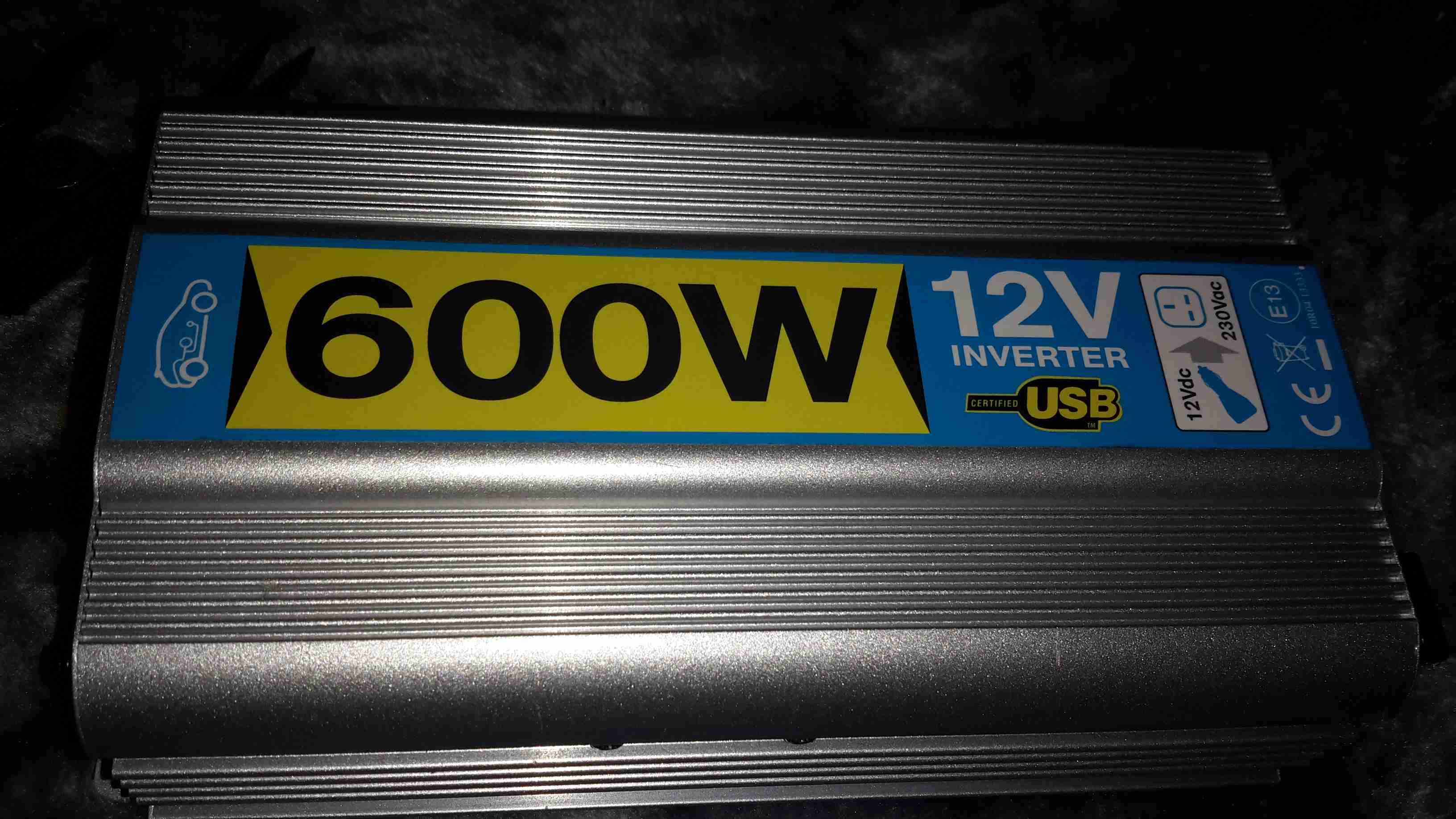
However I have decided to do a little analysis on a cheapo “600W” model that Maplin Electronics sells.
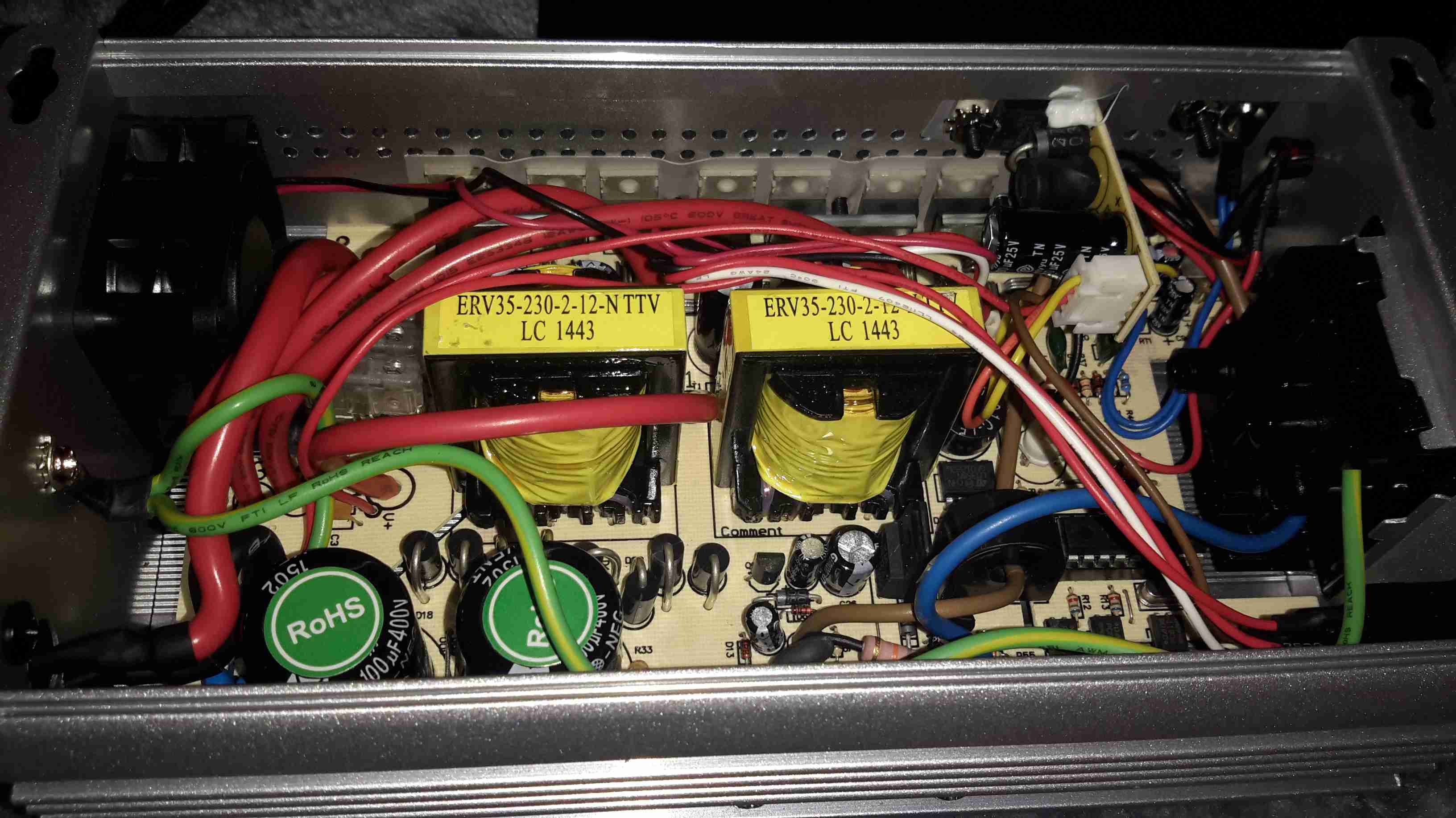
After a serious amount of metallic abuse, the bottom cover eventually came off. The sheet of steel used to close the bottom of the aluminium extrusion was wedged into place with what was probably a 10 ton hydraulic press.
As can be seen from the PCB, there’s no massive 50Hz power transformer, but a pair of high frequency switching transformers. Obviously this is to lighten the weight & the cost of the magnetics, but it does nothing for the quality of the AC output waveform.
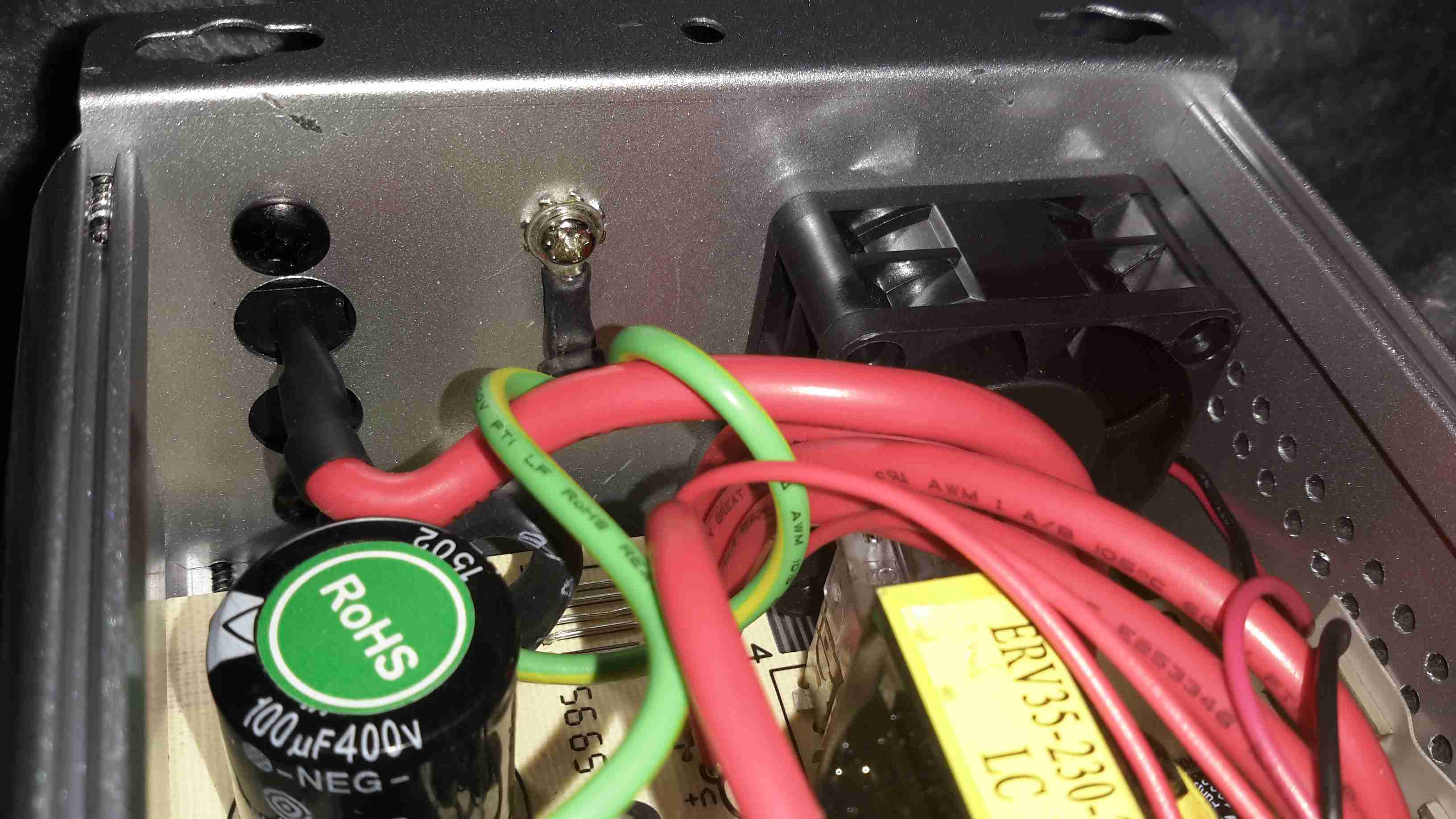
The 12v DC from the battery comes in on very heavy 8-gauge cables, this device is fused at 75A!
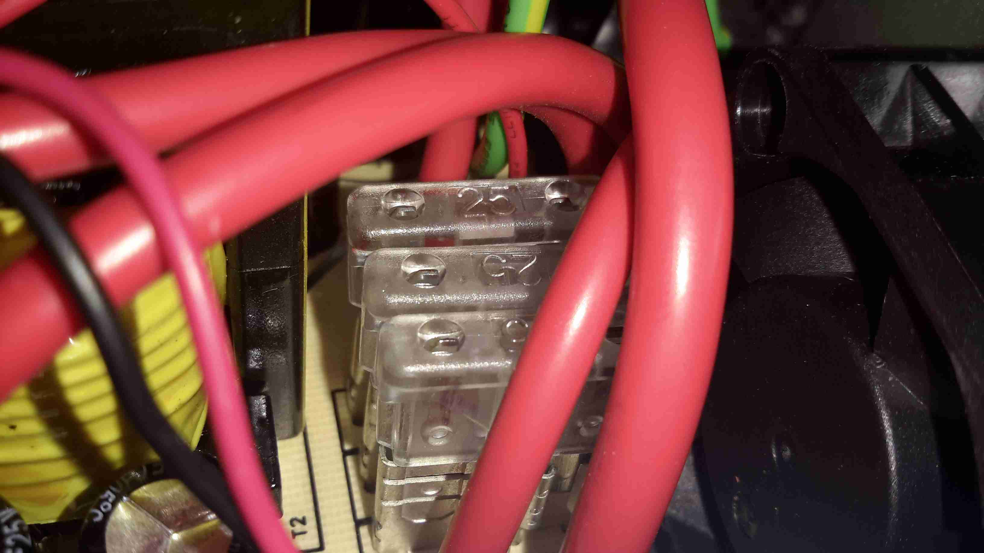
Here’s the fusing arrangement on the DC input stage, just 3 standard blade-type automotive fuses. Interestingly, these are very difficult to get at without a large hammer & some swearing, so I imagine if the user manages to blow these Maplin just expect the device to be thrown out.
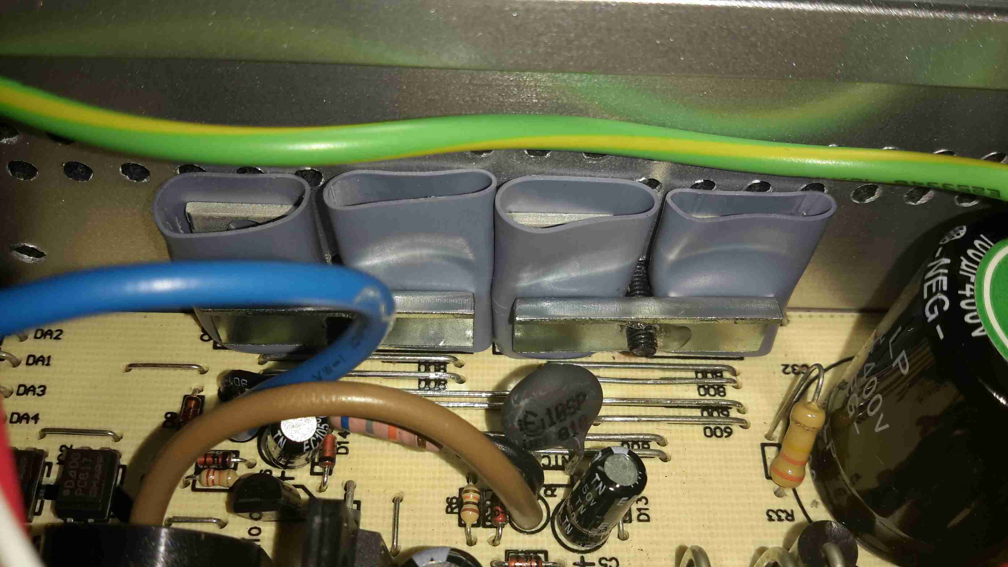
On the input side, the DC is switched into the pair of transformers to create a bipolar high voltage DC supply.
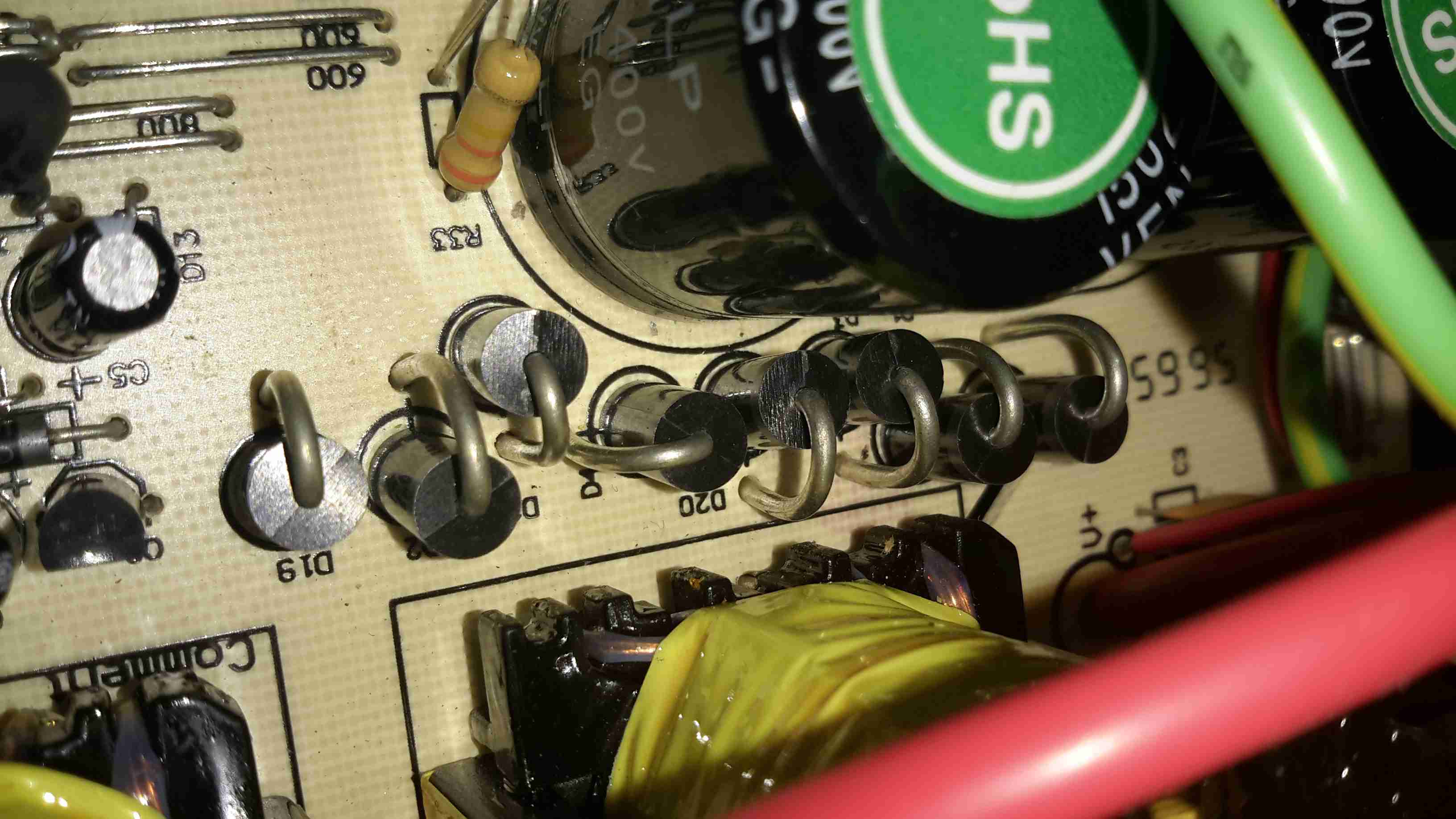
The large rectifier diodes on the outputs of the transformers feed into the 400v 100µF smoothing capacitors.
As mains AC is obviously a bipolar waveform, I’m guessing this is generating a ±150v DC supply.
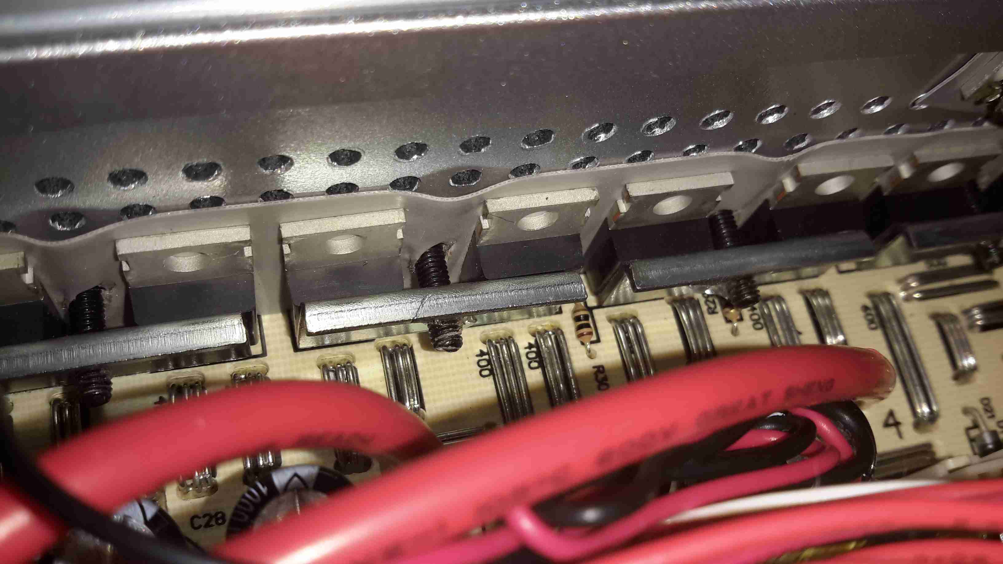
After the high voltage is rectified & smoothed, it’s switched through 4 more MOSFETs on the other side of the PCB to create the main AC output.
The label states this is a modified-sine output, so I’d expect something on the scope that looks like this:
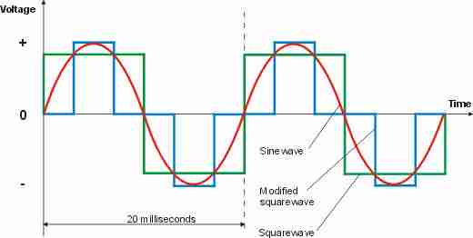
Modified-sine doesn’t look as bad as just a pure square output, but I suspect it’s a little hard on inductive loads & rectifiers.
However, after connecting the scope, here’s the actual waveform:

It’s horrific. It’s not even symmetrical. There isn’t even a true “neutral” either. The same waveform (in antiphase) is on the other mains socket terminal. This gives an RMS output voltage of 284v. Needless to say I didn’t try it under load, as I don’t possess anything I don’t mind destroying. (This is when incandescent lamps are *really* useful. Bloody EU ;)).
About the only thing that it’s accurate at reproducing is the 50Hz output, which it does pretty damn well.
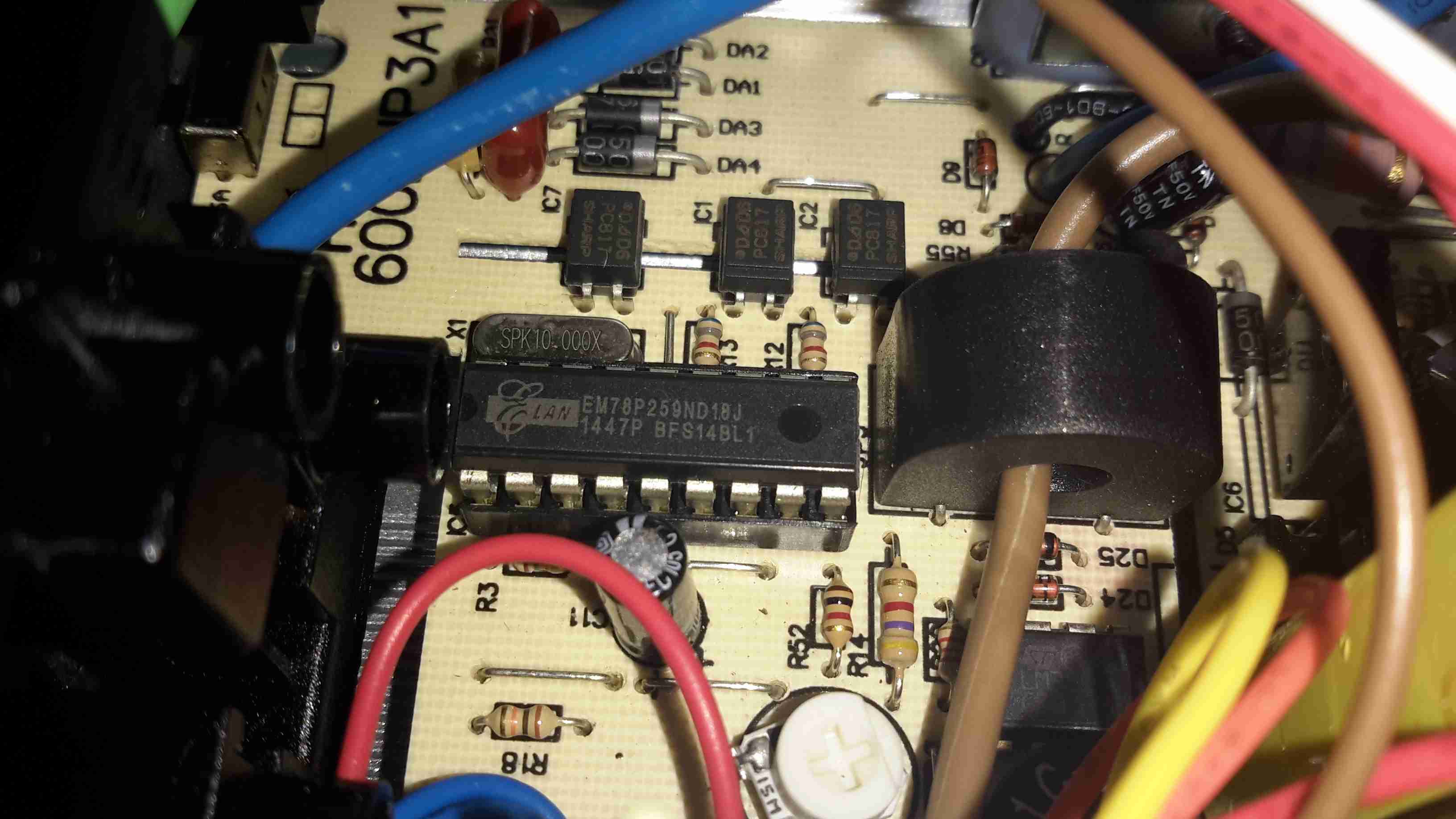
As is usual these days, the whole system is controlled via a microcontroller.

I have one of these inverters and had hardwired it into my van. it received very little use but recently I came to need it and when I switched it on……nothing! I took the device apart and discovered that all three paralleled 25A fuses were open circuit so I replaced them and reassembled the device. I then took it to my test bench and connected it to a nice, healthy, fully charged 12V lead acid battery and switched on. The green power LED came on and a couple of seconds later……..BEEP BEEP BEEP (pause) BEEP BEEP BEEP (pause), the low battery shutdown signal began and the AC output switched off. I’m just playing with it now for fun. I’ve noticed a small pot marked VR1 on the PCB and I’m wondering if it controls the threshold of the alarm signal. There doesn’t seem to be any schematics available for it, and I’m unsurprised at that, but I’m going to strip it down completely and see if I can trace out the circuit after which I’m going to fiddle until it blows up because after seeing your scope trace, there’s no way I’m connecting that output to anything. Fun times!
Hi Dale,
‘m not that surprised there’s no schematics available for this particular model, but the topology of these inverters is very similar between examples, so you might get some crossmatch from another unit that you can find schematics for.
Most of them seem to use a standard PWM driver IC.
You’re right – the waveform is utterly nasty – induction motors don’t seem to be bothered much by this, as I reckon the inductance might actually smooth the waveform out into more of a sine – I’m going to get some scope shots of this setup to see if I’m right! Anything with a SMPS though seems to generate a very nasty buzzing noise, probably from the cores of the common-mode chokes in the input filter network. I suspect such sharp edges may be quite destructive to rectifiers over time though.
IIRC, the pots on the board (and I don’t remember if there are two), control the output voltage & frequency, so be careful you don’t exceed the max working voltage of the HV rail electrolytics, unless you fancy a grenade on your workbench!