Posted on 5 Comments

EpEver Tracer 4210A MPPT Solar Charge Controller Teardown

Tracer 4210A MPPT Solar Controller

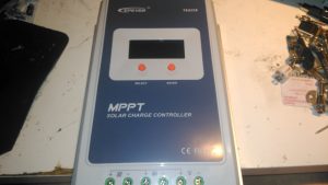
Here’s the solar charge controller to go with the MT50 from the last post. This is the 40A version of the EpEver Tracer A series, the 4210A. This unit is large, and very heavy. Most of this weight comes from the enormous heatsink which doubles as the mounting plate for all the other components, and the large inductors that are going to be required for the DC-DC conversion that MPPT requires.
Front Panel
Front Panel

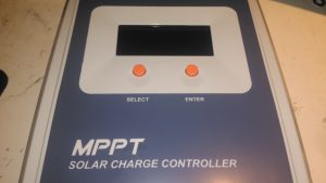
The front panel has a basic LCD, which shows various stats, such as PV Volts & Amps, and battery bank Volts & Amps. The pair of buttons are used to navigate the basic menu to configure some options, along with switching the load terminals ON/OFF.
Specifications
Specifications

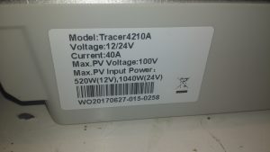
There’s a specs label on the top, with a slight difference here vs the manual, which states the max. PV volts as 92v.
Main PCB Overview
Main PCB Overview

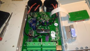
Removing 4 machine screws from the bottom of the unit allows the top to come off. Like the MT50 remote panel, this unit also has moulded-in brass thread inserts in the plastic parts. The PCB in here is heavily comformal coated, which stops me from reading the laser-etched numbers on the semiconductor devices, so there will be few details there.
Main PCB Lower
Main PCB Lower

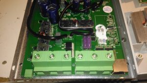
Here’s the bottom section of the main PCB, with the enormous screw terminals, which will easily take cables up to about 16mm². The RJ-45 jack which hosts the unit’s RS-485 bus is to the right, and a smaller 2-pin connector on the left sorts out the battery temperature sensor.
The DC output MOSFET switches are hiding just behind the right-hand terminals, there’s a pair of them in this unit to handle the output current. Some beefy diodes polarity-protect both the battery & PV inputs.
Board Centre
Board Centre

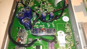
Moving up the board shows two 35A automotive blade fuses soldered into the board – these would be a real pain to replace if they ever blew, however with the electronic load current protection built into this unit, it’s an unlikely situation, unless something went hideously wrong. The main switching devices for the DC-DC converter are hidden – they’re clamped to the heatsink with the bars at right angles in the photo, I’m not going to dig any deeper into this just for those though – they’re just TO220 devices.
Under a load of thermal gunk on the right are 4 current shunt resistors, and the amplifiers for reading their values. These 1206-size SMD resistors looked a bit small for the power rating to me, but they’re heatsinked in operation to a small heatsink mounted in the top cover.
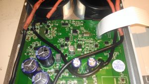
Board Upper
Board Upper

The upper section of the PCB hosts the main microcontroller, and the connections over to the front panel LCD & buttons. Couldn’t really get much info from these chips, due to the conformal coating.
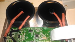
Toroidal Inductors
Toroidal Inductors

Right at the top of the unit are these toroidal inductors, potted into aluminium housings. The copper windings of these is very heavy – at least 2.5mm². They’re electrically in parallel, the 20A version would only have a single inductor.
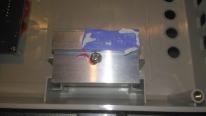
Current Shunt Heatsink

This small heatsink sits inside the top cover, and provides some cooling to the current shunts.
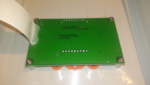
Display Board
Display Board

Not much to say for the display board, there’s going to be nothing here apart from an I²C LCD driver & the pair of front panel buttons, so I won’t bother removing this from the case.
Posted on Leave a comment

nb Tanya Louise Radio Install Part 1

I often find myself carrying by go bag up to the boat during trips, so I can do some radio. However at 16lbs it’s a pain on public transport. A fixed radio was required! Another Wouxun GK-UV950P was ordered, and the fact that the head unit is detachable from this radio makes a clean install much easier.

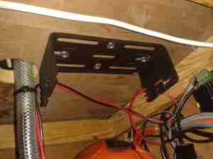
Mounting Bracket
Mounting Bracket

I found a nice spot under a shelf for the main radio unit, above is the mounting bracket installed.
This location is pretty much directly behind where the head unit is placed, but the audio is a bit muffled by the wooden frame of the boat & some external speakers will be required for the future.

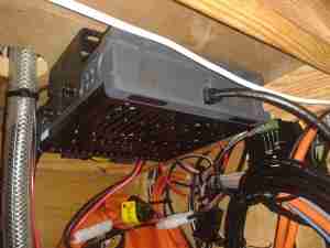
Main Radio Unit
Main Radio Unit

Here’s the main radio unit mounted on it’s bracket, with the speakers facing down to improve the audio slightly. I used the supplied interface cable for the head unit, even though it’s too long. I do have the tools to swage on new RJ-45s, but the stuff is a pain to terminate nicely & I really just couldn’t be bothered. So it’s just coiled up with some ties to keep it tidy. Main power is provided directly from the main DC bus. (880Ah total battery capacity, plus 90A engine alternator, 40A solar capacity).

Rat's Nest
Rat’s Nest

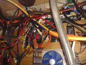
Here’s the main DC bus, with the distribution bars. With the addition of new circuits over the years, this has become a little messy. At some point some labelling would be a good idea!

Radio Face Plate
Radio Face Plate

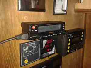
Finally, the head unit is installed in a spot on the main panel. It does stick out a little more than I’d like, but it’s a lot of very dusty work with the router to make a nice hole to sink it further in. All my local repeaters & 2m/70cm simplex are programmed in at the moment.

Antenna Magmount
Antenna Magmount

I’ve got a Nagoya SP-80 antenna on a magmount for the radio, a magmount being used due to the many low bridges & trees on the canal. (It’s on the roof next to the first solar panel above). I prefer it to just fall over instead of having the antenna bend if anything hits it!

Part 2 will be coming soon with details of the permanent antenna feeder.

73s for now!

Posted on Leave a comment

Solar Cable Upgrade & Pseudo-MPPT

New Cable
New Cable

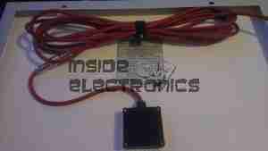
As the cable supplied with the panel is far too short, inflexible & does not even allow the cable gland on the terminal box to form a seal, I have replaced it with some high quality twin core guitar cable, with silicone insulation.

The cable is removable from the panel tail by means of a screwlock two pin connector.


On another note, I have noticed a side effect of fitting a switchmode regulator to the panel: it seems to have formed an MPPT-type regulator setup, as even in low light conditions, when the bare panel is outputting 18.5v at 50mA short circuit, with the switching regulator I can get a useable 13.25v at ~170mA.
This effect is increased in full light, where I can obtain 4.5A short circuit current & ~1.8A at 13.25v output.

Posted on Leave a comment

Wearable Raspberry Pi – Solar Charging


24W Solar Panel
24W Solar Panel

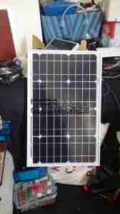
I have acquired a 24W monocrystalline solar panel to charge my portable battery pack while on the move. This panel will be able to charge all devices I carry on a regular basis with nothing but some sunlight!

Info Panel
Info Panel

Info on the panel itself. Rated at 24W with nominal 17.6v DC, 1.36A output.

Regulator
Regulator

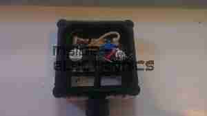
I have installed a switching regulator in the back of the panel, where the connections would normally be wired straight to the array of cells. This regulates the voltage down to a constant 13.8v to provide more compatibility with 12v charging equipment. I have tested the output of the panel in late day sun, at 1.27A.