As part of the giant power bank that gets dragged to all my major camping trips & festivals, there is an old Eberspacher Diesel heater, a D1LCC from at first guess somewhere in the mid 90’s. At only 1.8kW heat output this is a little small for our current tent, and it struggles to keep the temperature comfortable at night, so with Chinese clones on the market these days much cheaper than the Eberspacher or Webasto units, a replacement was up! Still, the old Eberspacher is in working order, and will probably get used for some other project.
Diesel Heaters
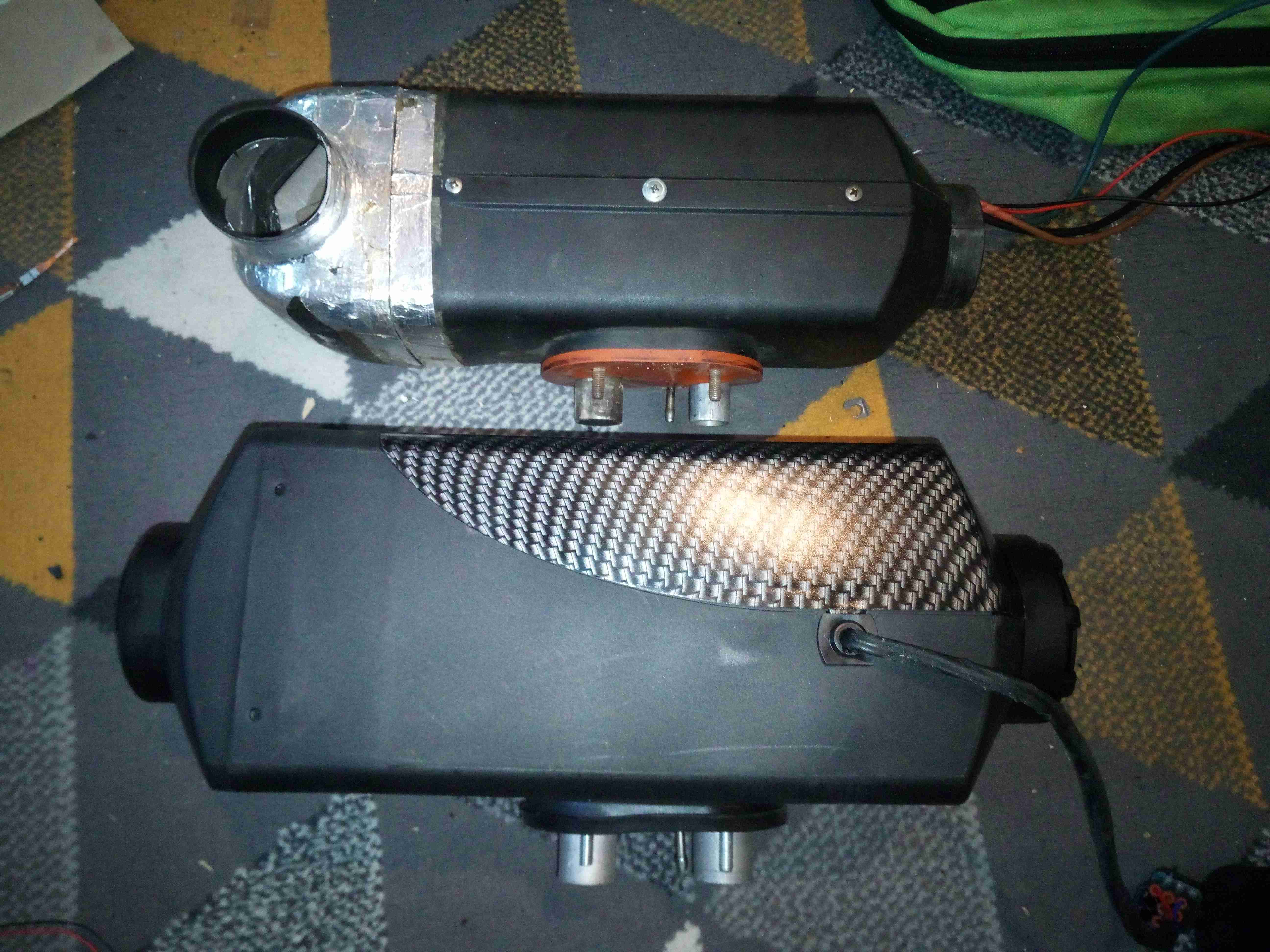
After removing the old D1LCC & placing it next to the new one, the size difference is obvious! The new heater is a Chinese clone of the Eberspacher D4 unit, allegedly uprated to 8kW. (In reality, it’s probably around 5kW heat output at full tilt). Luckily, it’s not that much larger than the old one, so it’ll go into the same space.
New Heater
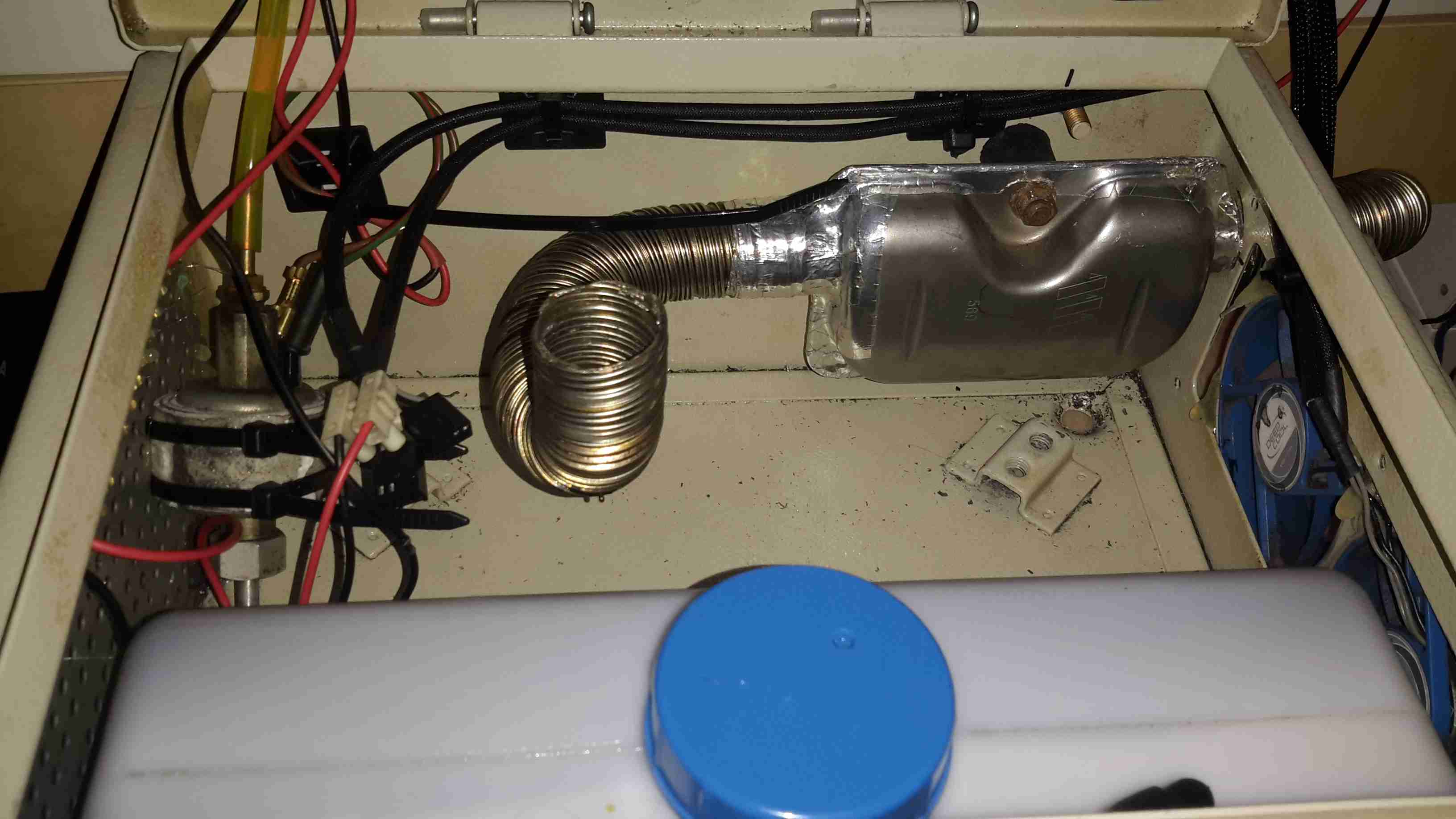
The port layout on the bottom of the heater is identical apart from intake port size, a quick attack of the baseplate with a grinder to remove the old hole pattern allowed the supplied mounting plate to fit correctly into place for the new heater. The duct size on this unit is also bigger than the old 60mm – 75mm duct is used on these large units. No modification to the vent hole was required, as the 75mm vent already fit perfectly. To clear the fittings on the top of the fuel tank, which is just underneath the hot air exhaust cowling of the heater, the mounting plate is fixed using 10mm nylon standoffs, this also helps get a bit more natural airflow around the base of the heater, as the mounting gets to 90°C in operation at full power!
These heaters don’t use the Eberspacher standard switch wire for control – there are only 3 pins in the loom to the controller, for 5v power & an odd UART which uses gated TX/RX to avoid having a separate line for each.
Stock Controller
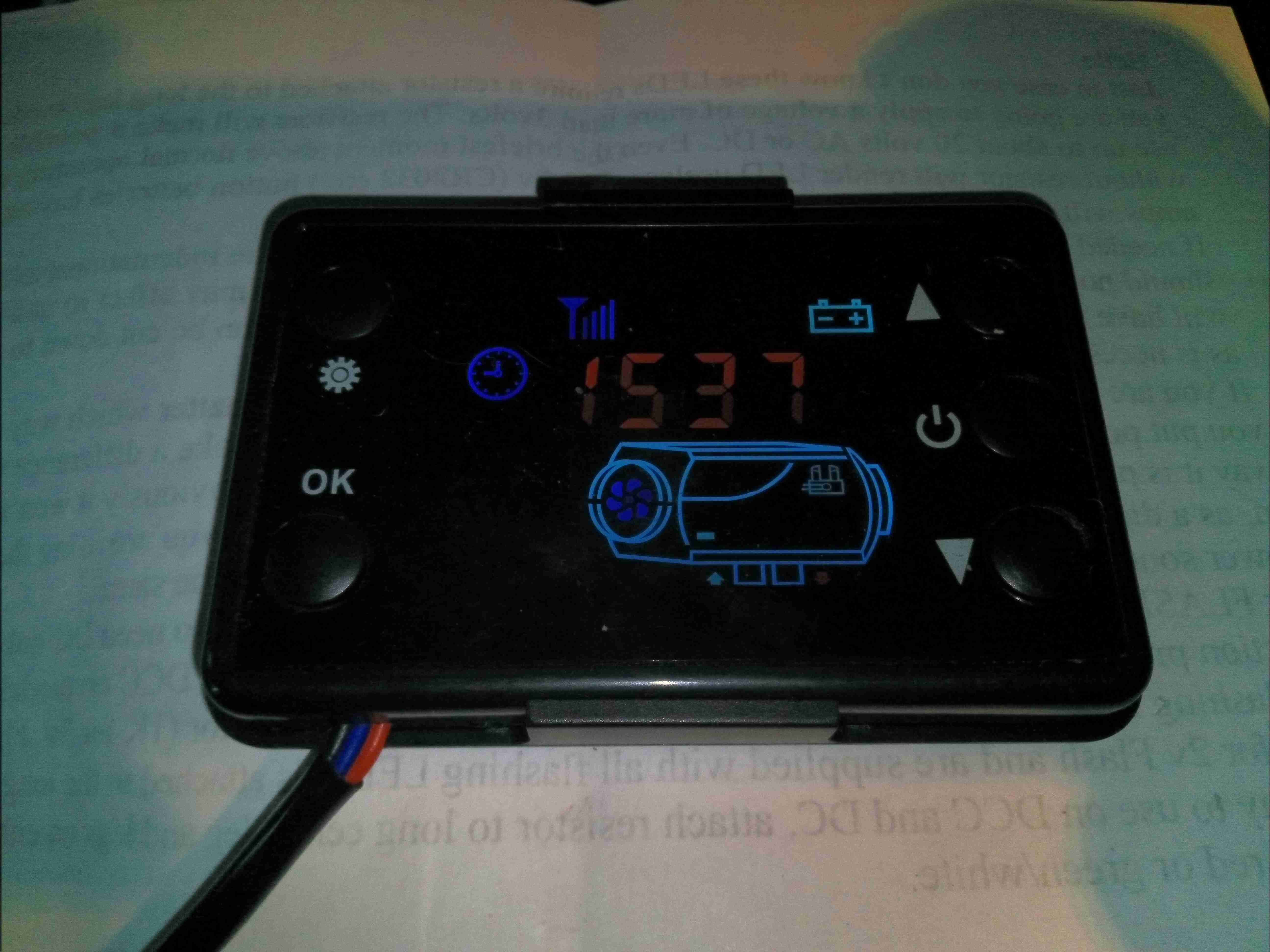
The stock controller has quite a nice looking LCD display, but it’s less than responsive & the backlight is always on at full tilt. It’s also much larger than the Eberspacher 701 controller so would require some rejigging of the control panel on the trolley. The built-in thermostat is also inaccurate, being almost 5°C high no matter what the room temperature. Ray Jones from Down Under has designed an open source ESP32 based controller for these heaters, and one of these is currently being built to control the unit. More to come on this bit!
Stock Controller PCB
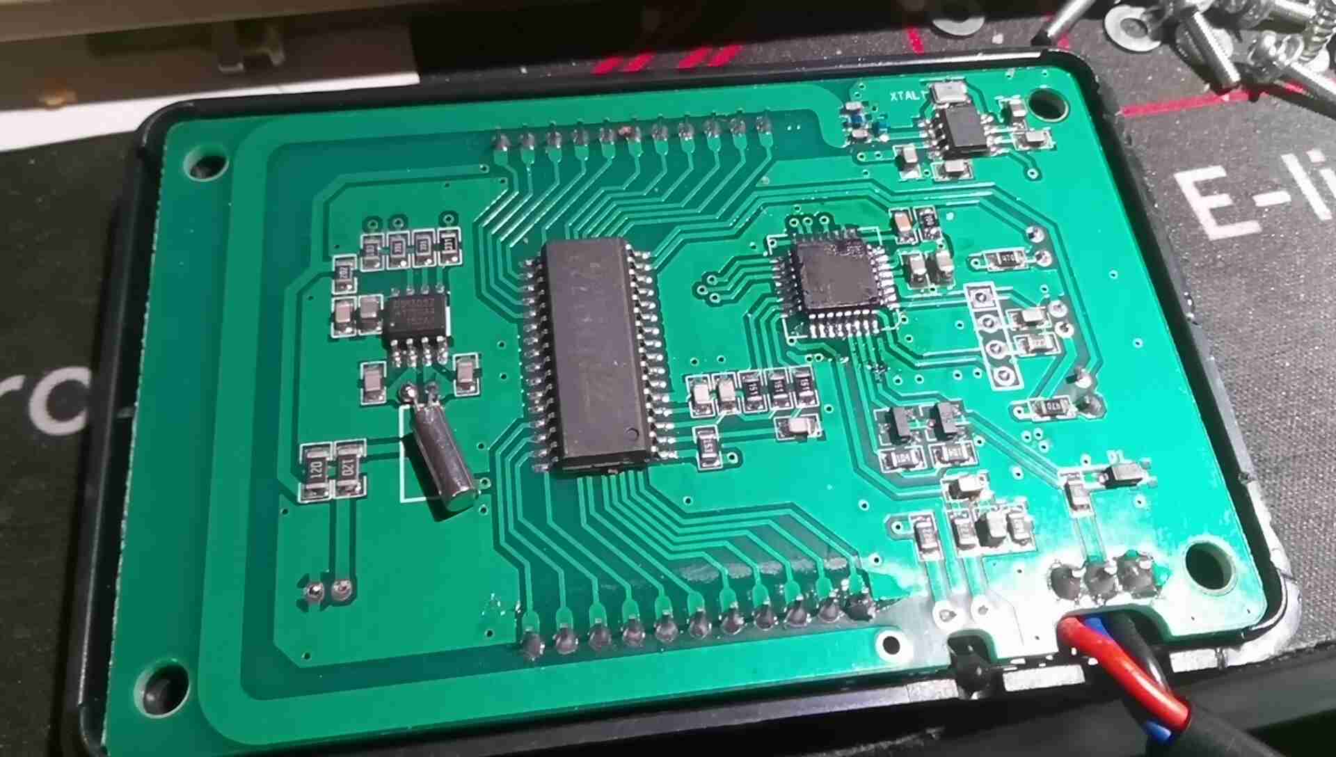
A quick teardown of the controller reveals pretty simple internals, there’s a microcontroller, probably an STM8 device by looking at the programming header, but the markings have been scrubbed off the IC. There’s a standard LCD controller IC, a RTC which isn’t battery backed, and a 433MHz receiver IC with PCB trace antenna.
I wasn’t able to get the remote control function working with any of the remotes I have, any attempt at pairing a remote didn’t give any response from the controller unit. I also tried a 315MHz remote, but that didn’t work either. Not an issue since I’m building a much better open source controller.
Fuel & Exhaust
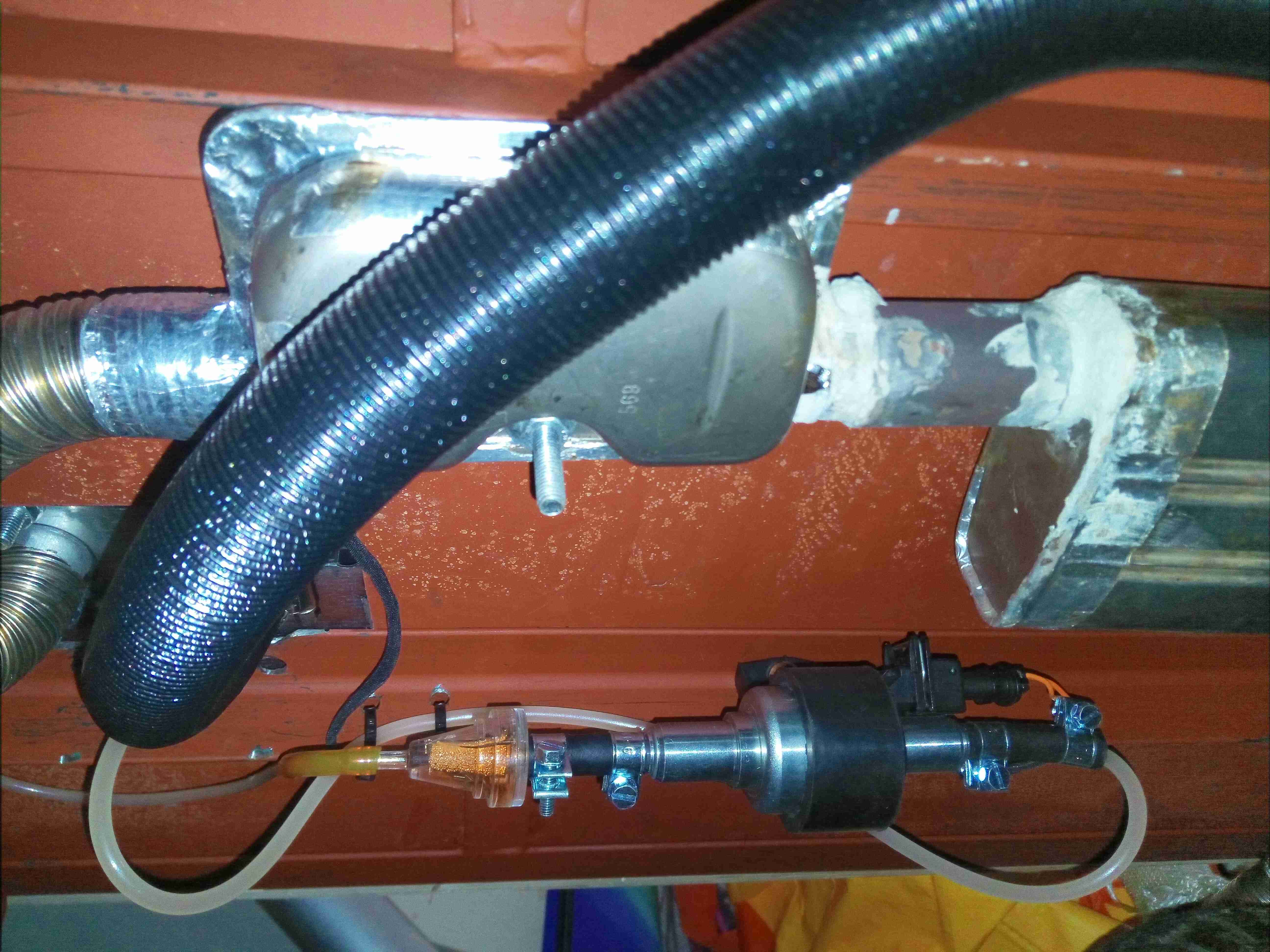
Under the base is the exhaust system & the fuel dosing pump. There’s a small filter in the feed line from the tank to keep crap out of the pump, and nylon fuel line then runs the fuel to the heater inlet. The exhaust is made as gas-tight as possible with foil tape & exhaust paste, to keep the exhaust fumes contained in the pipework until they’re vented outside. The rest of the exhaust after the right hand silencer is done in brazed 22mm copper pipe, and a piece of Eberspacher exhaust duct is removable from the final exhaust tail for storage. The black pipe is the combustion air intake, which is simply fed into a silencer cable tied to the trolley frame.
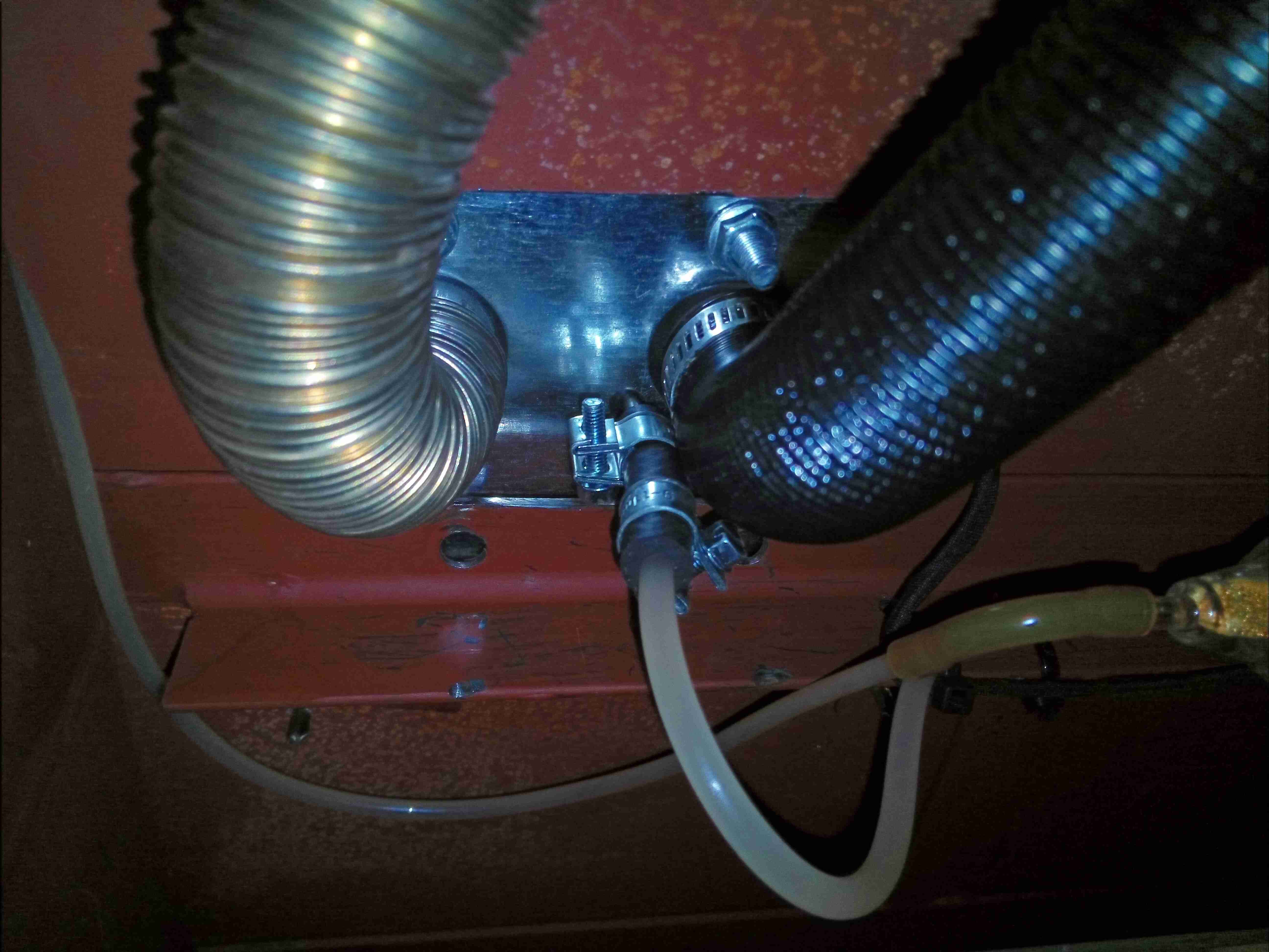
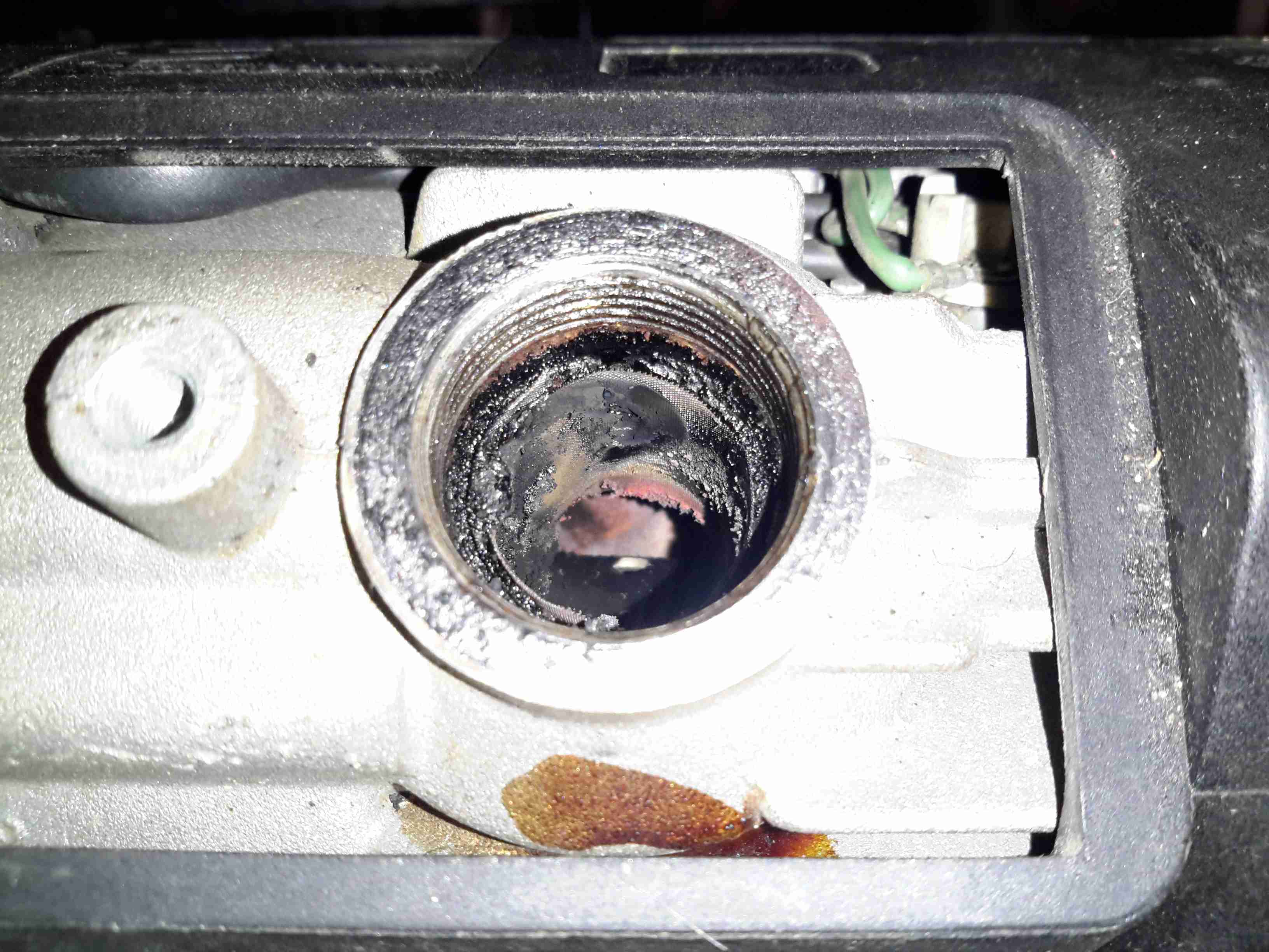
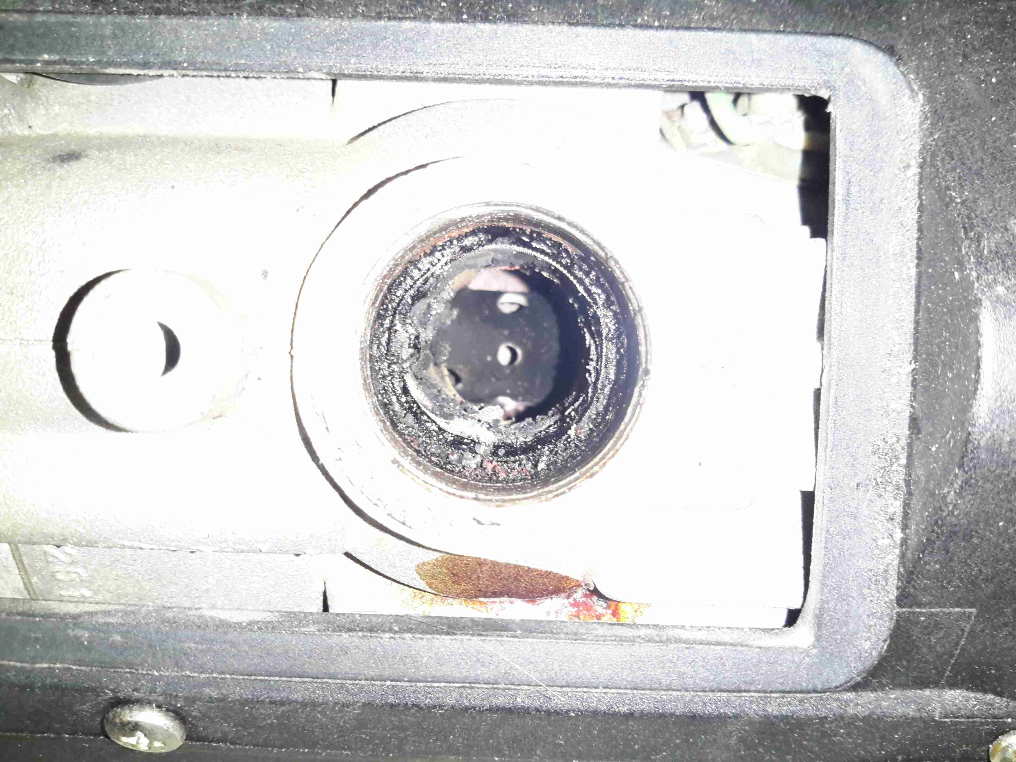
Heater Ports
The 3 ports are visible under the mounting plate, the square hole cut out of the trolley base to accommodate everything.
Since I do festivals every year, along with a couple of other camping trips if the weather is good enough, I’ve been taking equipment with me for years in flight cases to make things more comfortable. Things like a large battery to power lights & device charging, an old Eberspacher diesel heater for the times when the weather isn’t great, and an inverter to run the pumps built into airbeds.
Red Diesel / Heating Oil is my fuel of choice for camping purposes, as it’s about the safest fuel around, unlike Butane/LPG it is not explosive, will not burn very readily unless it’s atomized properly & it’s very cheap. Paraffin is an alternative fuel, but it’s expensive in the UK, at about £12 per 5L.
The Hexamine-based tablet fuels the UK festivals promote is nasty stuff, and the resulting combustion products are nastier still. (Things like Hydrogen Cyanide, Formaldehyde, Ammonia, NOX). They also leave a sticky black grok on every cooking pot that’s damn near impossible to remove. Meths / Trangia stoves are perfectly usable, but the flame is totally invisible, and the flammability of alcohol has always made me nervous when you’ve got a small pot of the stuff boiling while it’s in operation in the middle of a campsite filled with sloshed festival goers. A single well-placed kick could start a massive fire.
Previous System
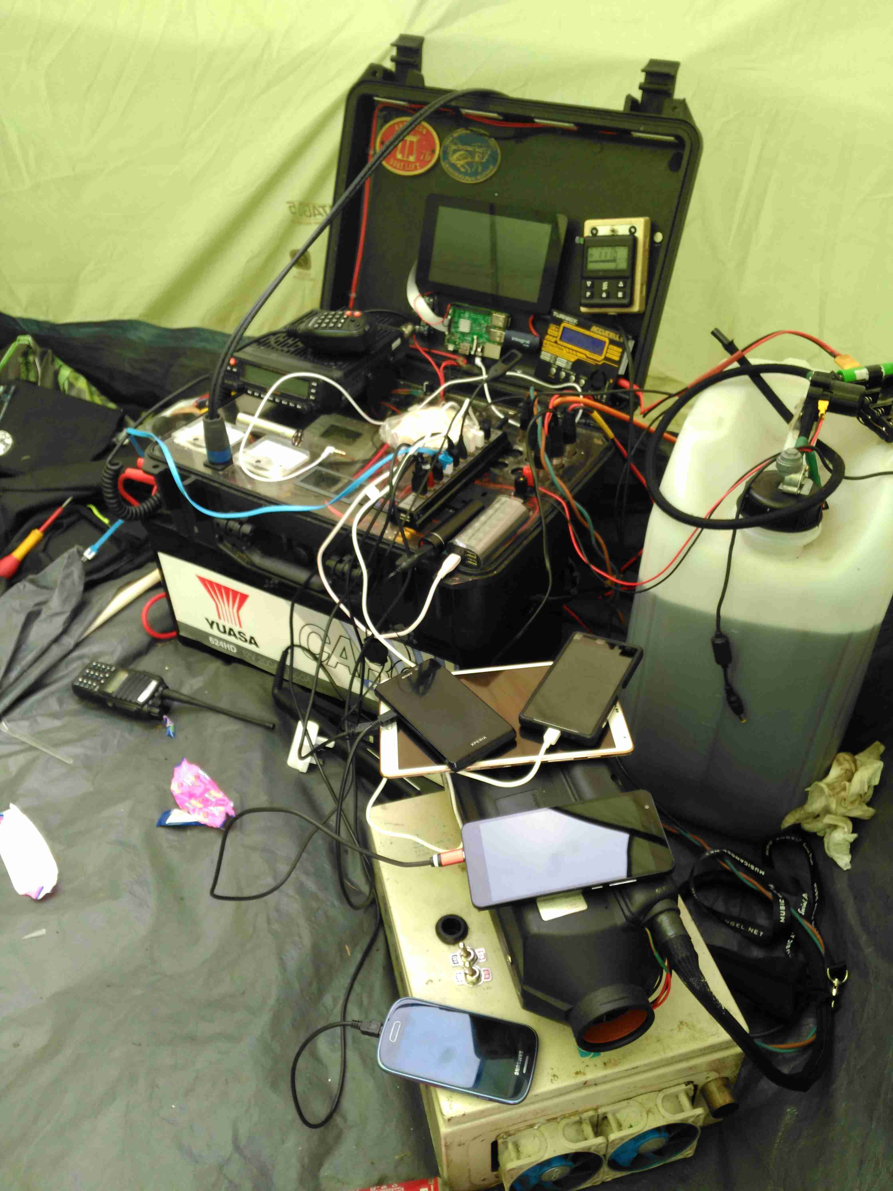
Over the years the gear has evolved and grown in size, so I decided building everything into one unit on wheels would be the best way forward. I’ve been working on this for some time, so it’s time to get some of the details on the blog! Above you can see the system used for last year’s camping, the heater is separate, with a 25L drum of heating oil, the battery is underneath the flight case containing all the power components, and it’s currently charging All The Things.
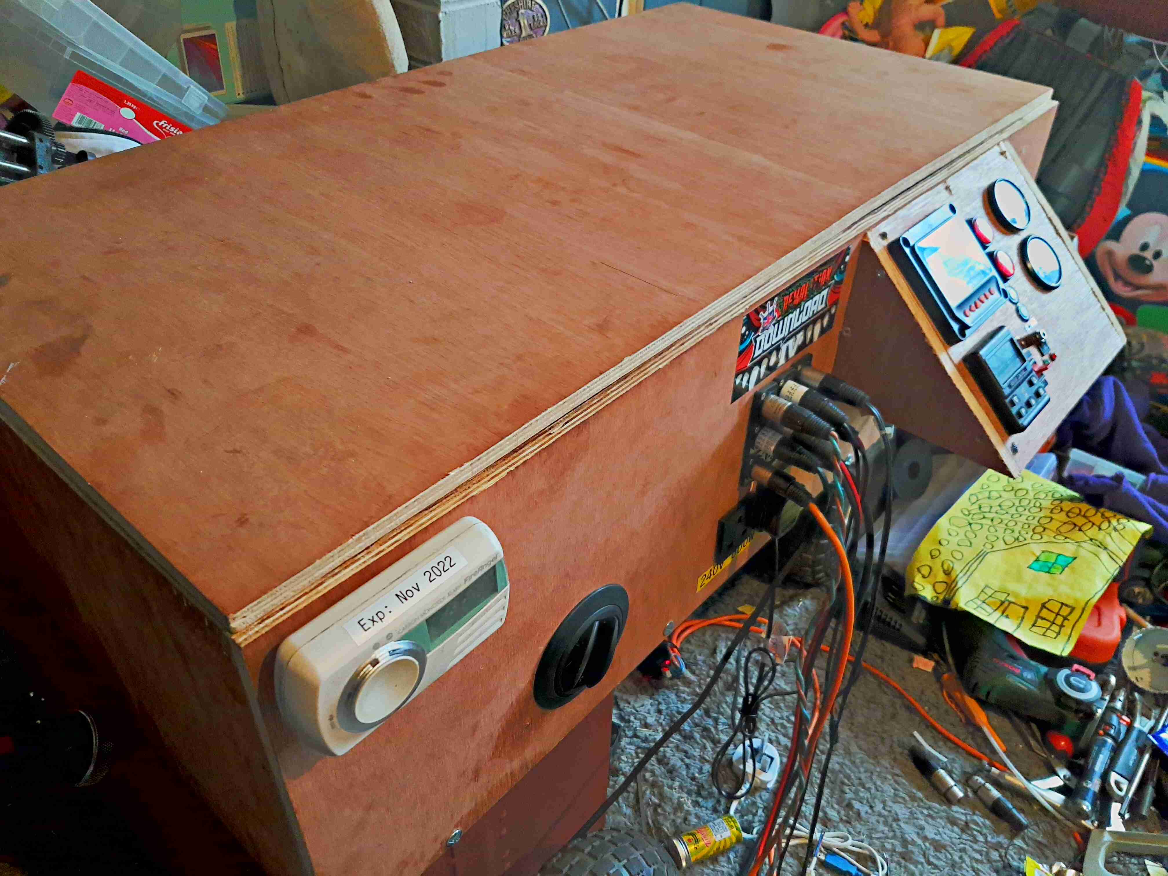
Overview
Above is the new unit almost finished, the bottom frame is a standard eBay-grade 4-wheel trolley with a few modifications of my own, with a new top box built from 12mm hardwood marine plywood. This top is secured in place with coach bolts through the 25mm angle iron of the trolley base. The essential carbon monoxide detector is fitted at the corner.
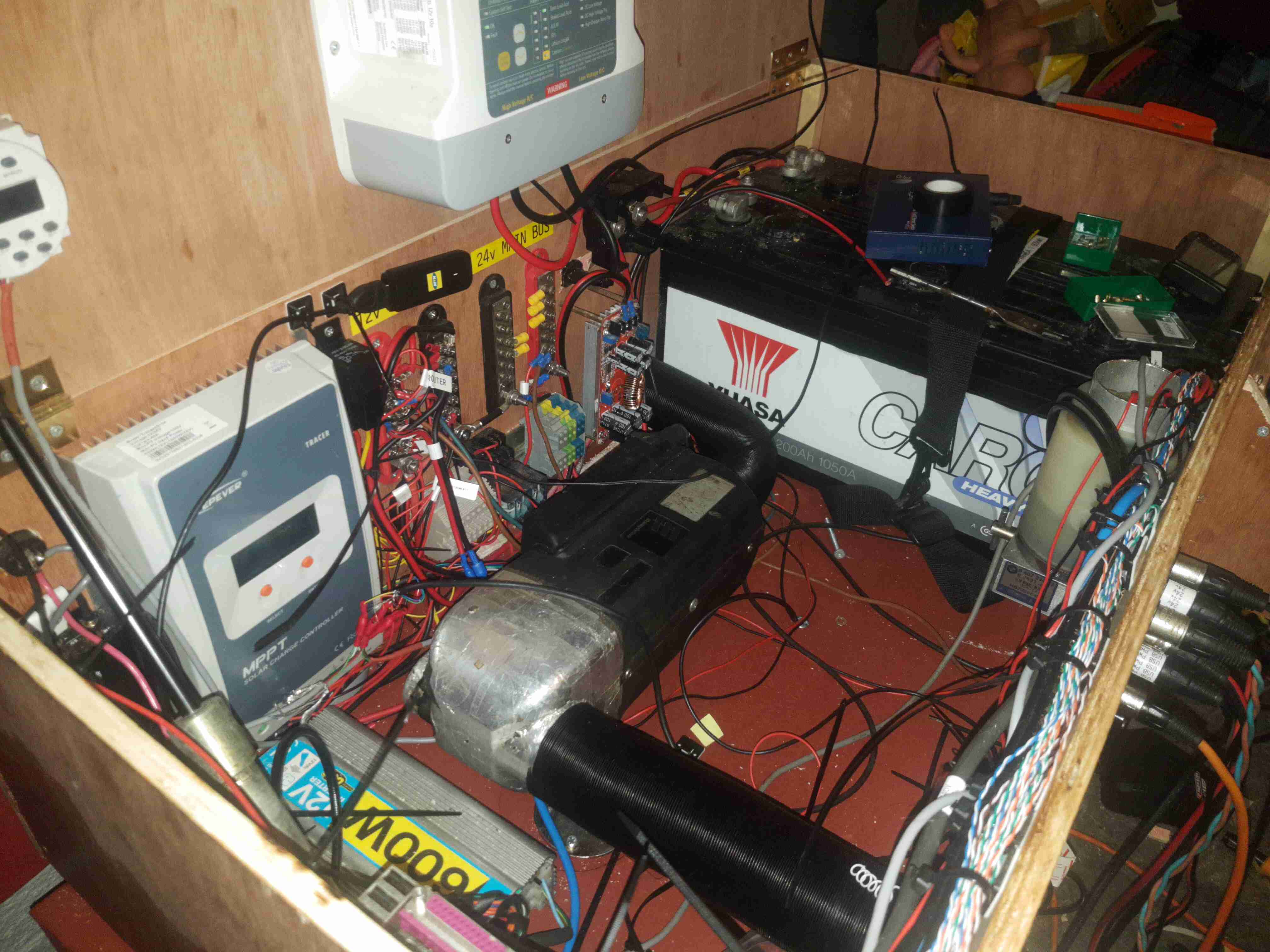
Internal View
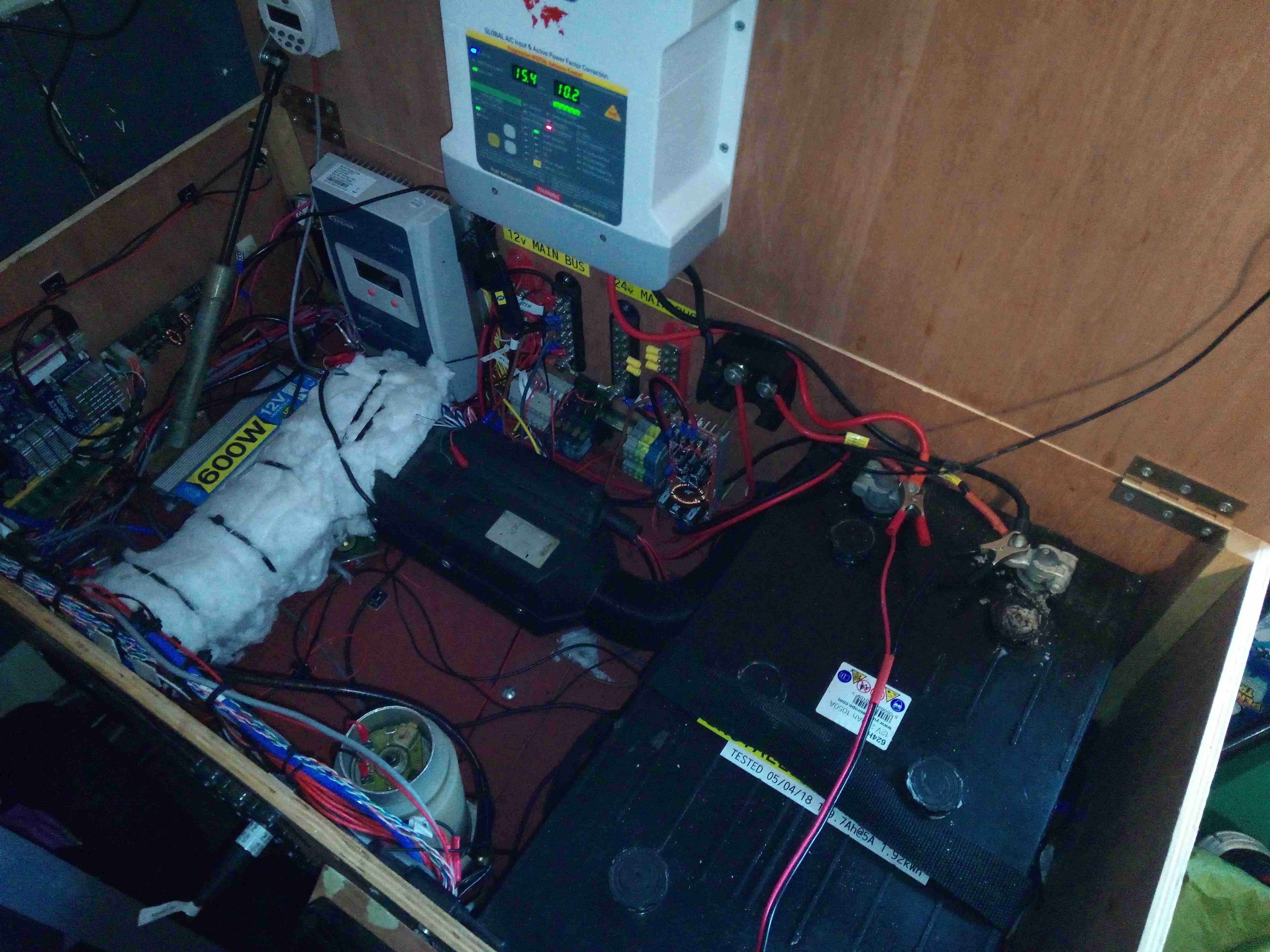
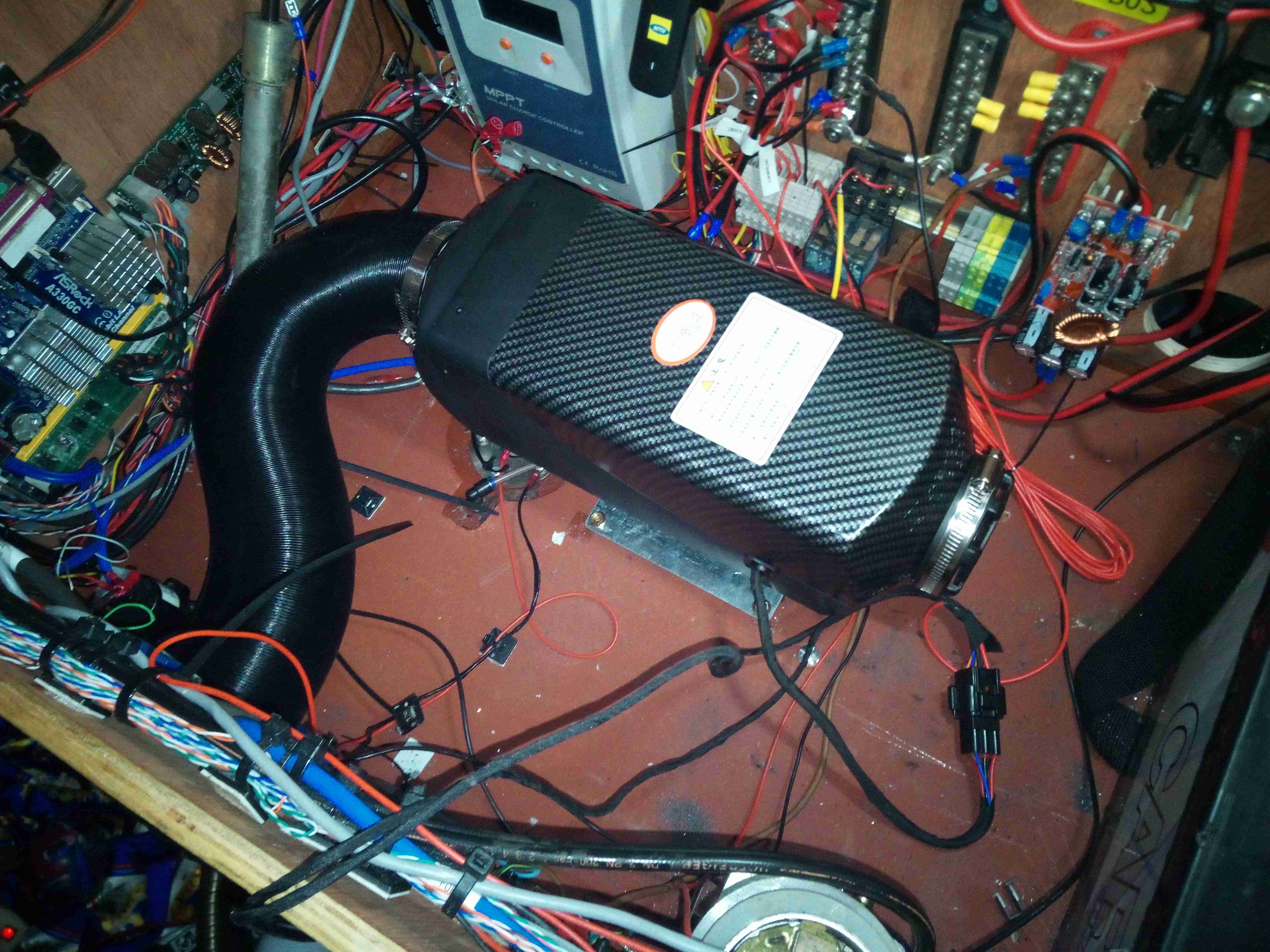
The inside gets a bit busy with everything crammed in. The large Yuasa 200Ah lead-acid battery is at the far end, with it’s isolation switch. Right in the middle is the Eberspacher heater with it’s hot air ducting. I’ve fitted my usual 12/24v dual voltage system here, with the 24v rail generated from a large 1200W DC-DC converter.
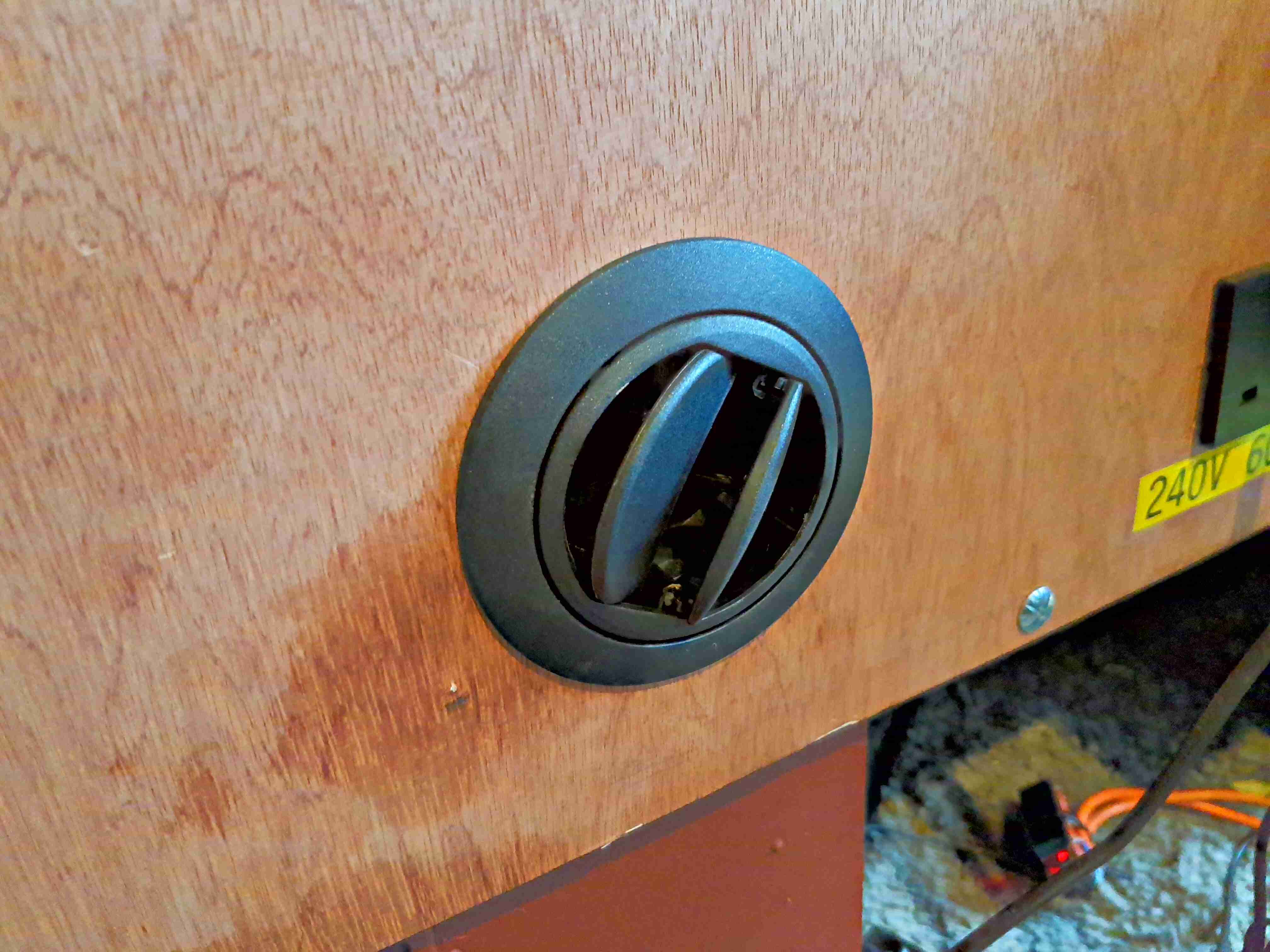
Heater Vent
The hot air duct for the heater is fed out through a standard vent in the front. Very handy for drying out after a wet day.
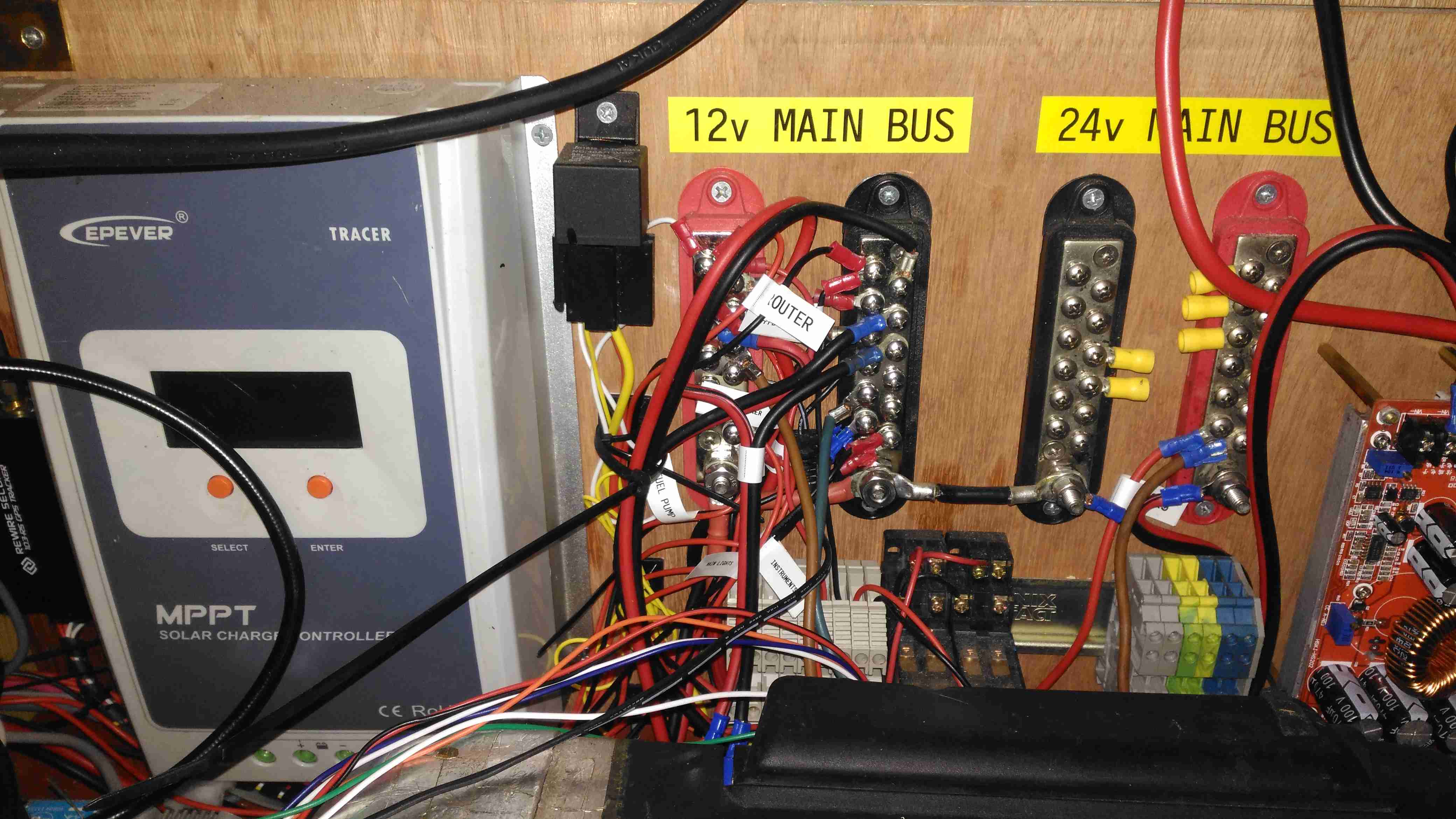
Main Bus Bars & Solar Controller
Here’s a closeup of the distribution bus bars, with both negative rails tied together in the centre to keep the positives as far away from each other as possible, to reduce the possibility of a short circuit between the two when working on the wiring. The EpEver Tracer 4210A MPPT Solar Charge Controller is on the left, tucked into the corner. This controller implements the main circuit protection for the battery, having a 40A limit. Individual circuits are separately fused where required. Solar input on this unit is going to be initially provided by a pair of 100W flexible panels in series for a 48v solar bus, the flexible panels are essential here as most of the festivals I attend do not allow glass of any kind onsite, not to mention the weight of rigid panels is a pain.
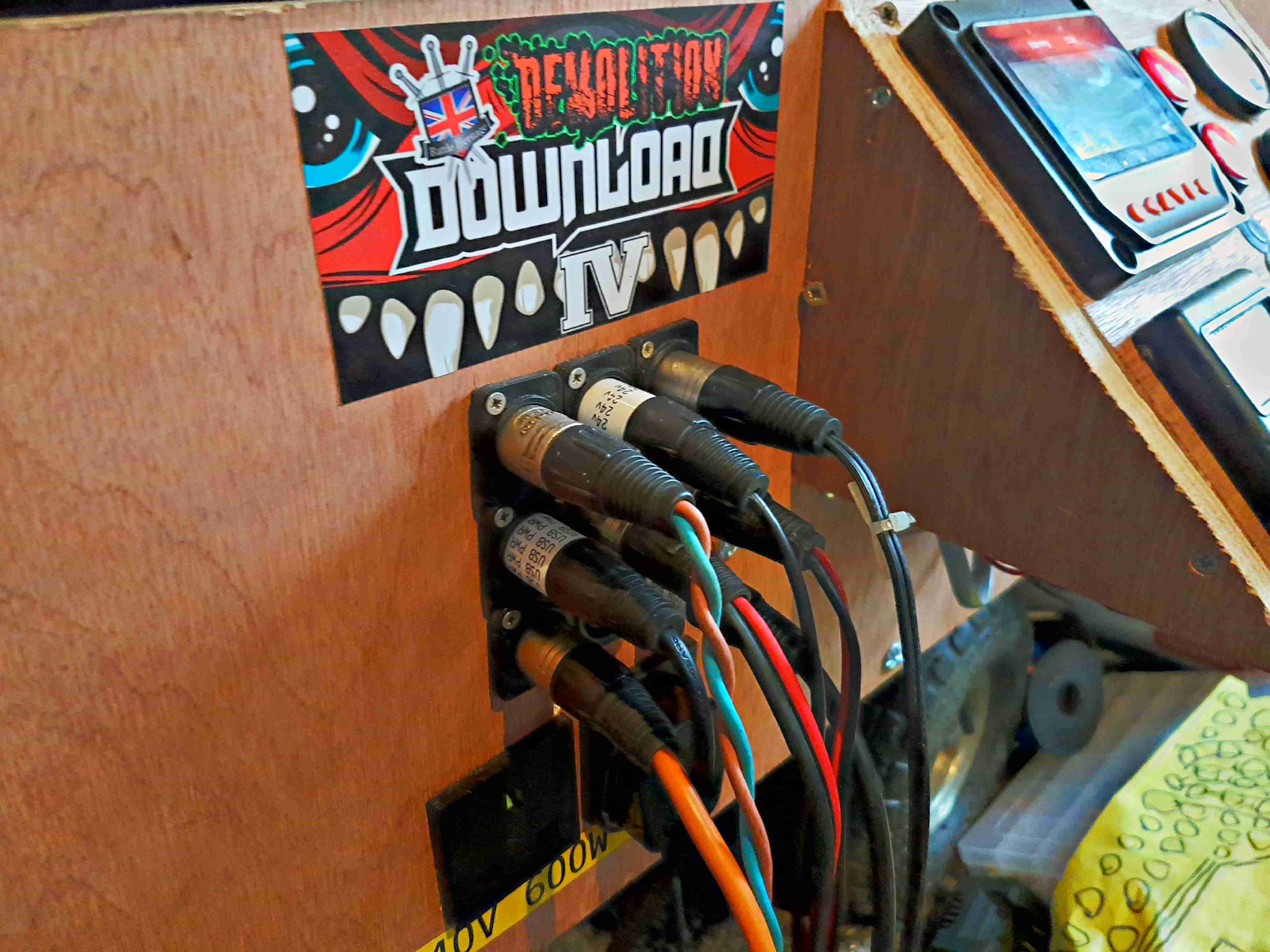
DC Output Sockets
I’ve stuck with the 3-pin XLR plugs for power in this design, giving both the 12v rail, 24v rail & ground.
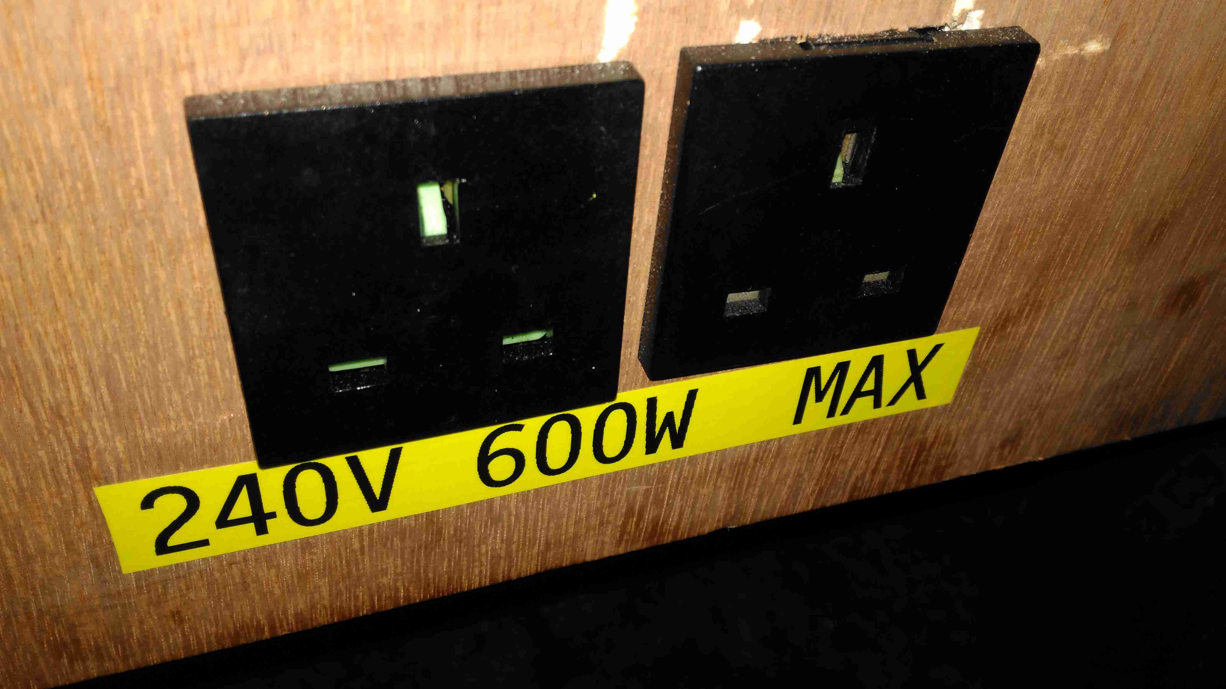
Inverter Outputs
Tucked under the DC outputs are a pair of panel sockets for the 600W inverter. This cheapo Maplin unit is only usually used to pump up air beds, so I’m not expecting anyone to pull anything near max output, but a warning label always helps.
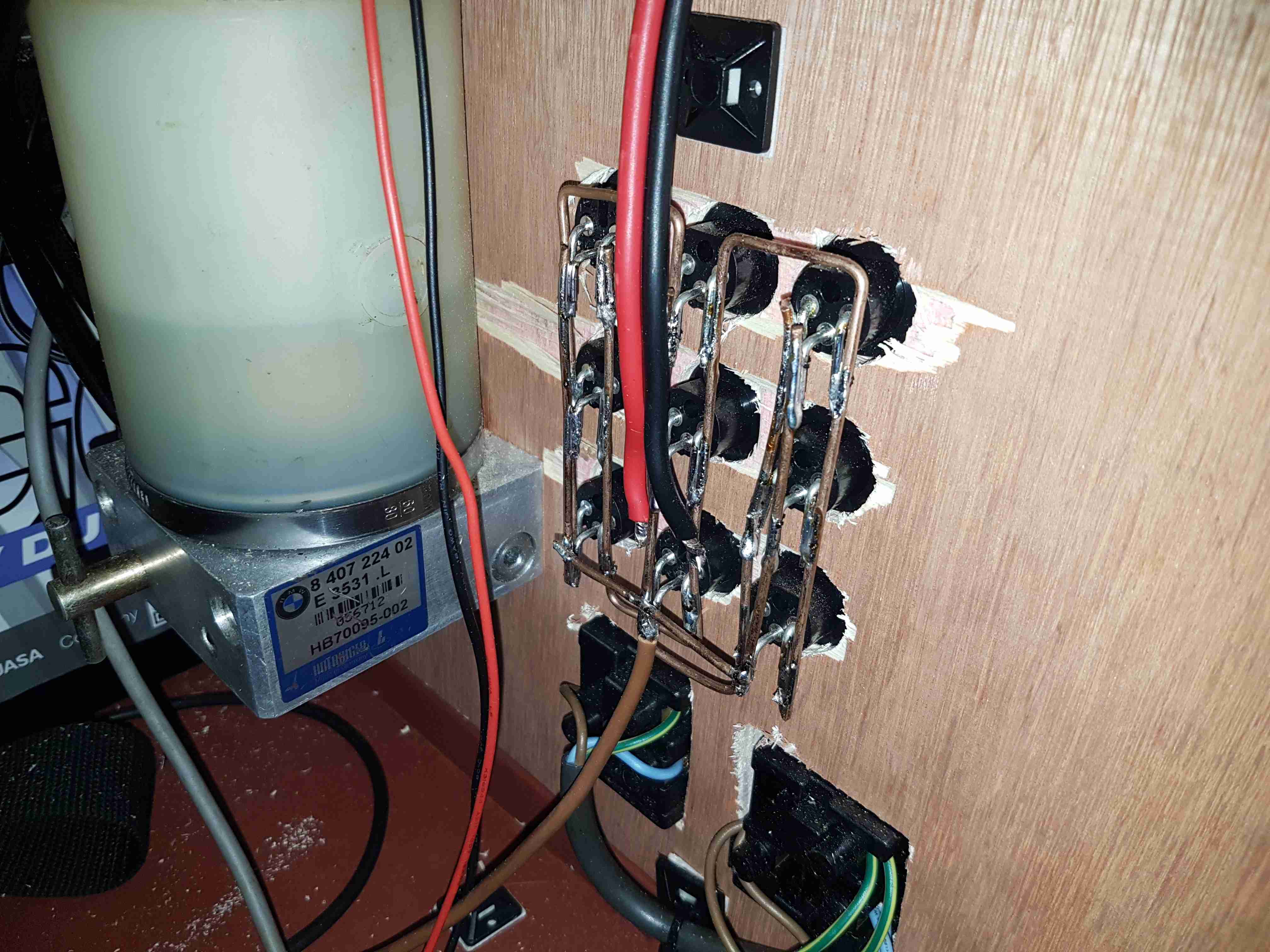
Power Socket Wiring
Behind the front panel is the hardwiring for the power sockets. The DC jacks are connected together using 2mm solid copper wire, bent into bus bars.The mains wiring underneath is a simple radial circuit straight from the inverter. The large cylinder on the left is a hydraulic pump from a BMW Z3, which runs a hydraulic cylinder for lifting the lid of the top box, used simply because I had one in the box of junk.
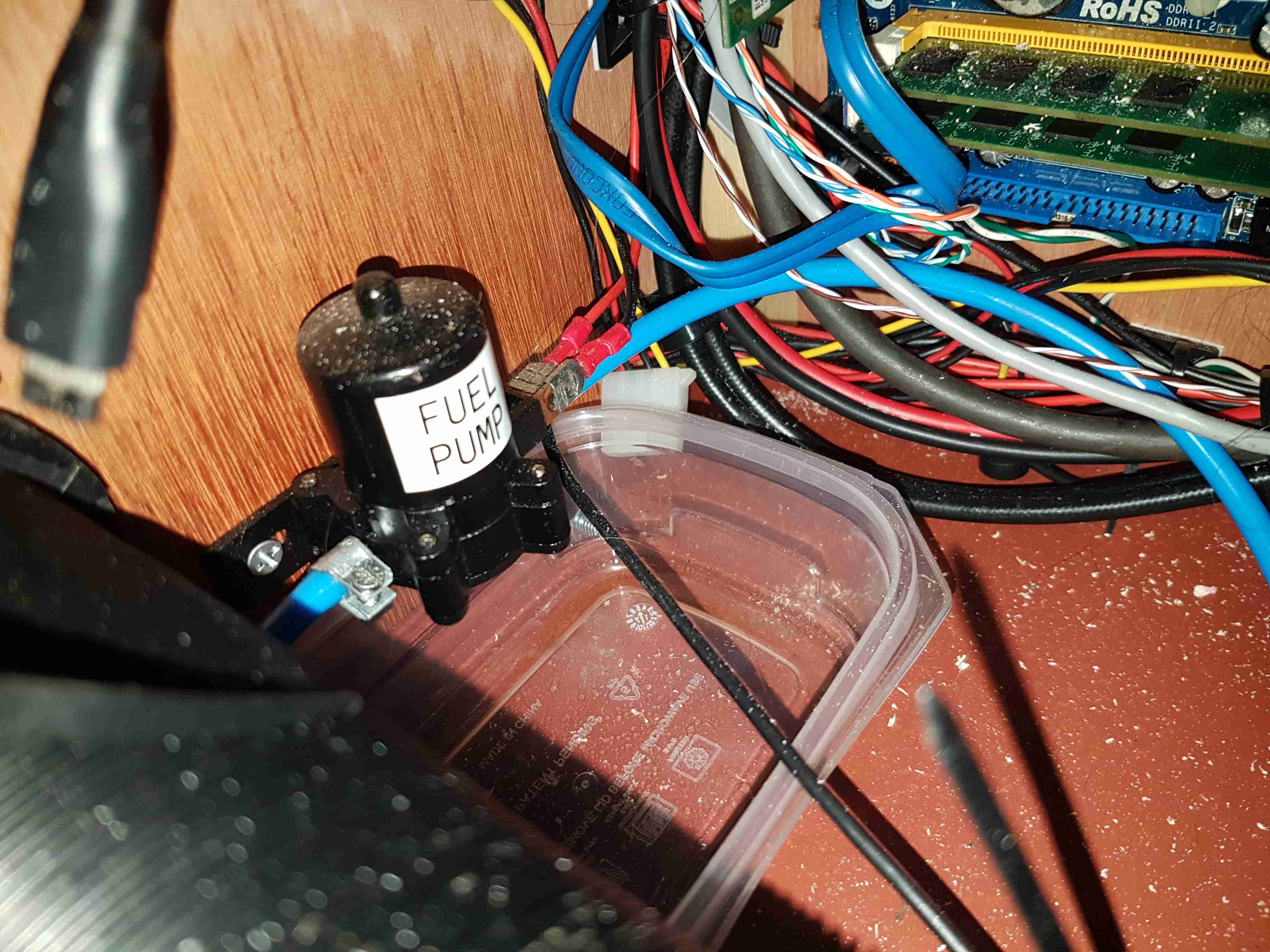
Fuel Pump
External fuelling is dealt with by a small gear pump, this is used to fuel up the Optimus Stove & Petromax Lantern. This is in fact a car windscreen wash pump, but it has coped well with pumping hydrocarbons, it currently has a small leak on the hose connections, but the seals are still entirely intact.
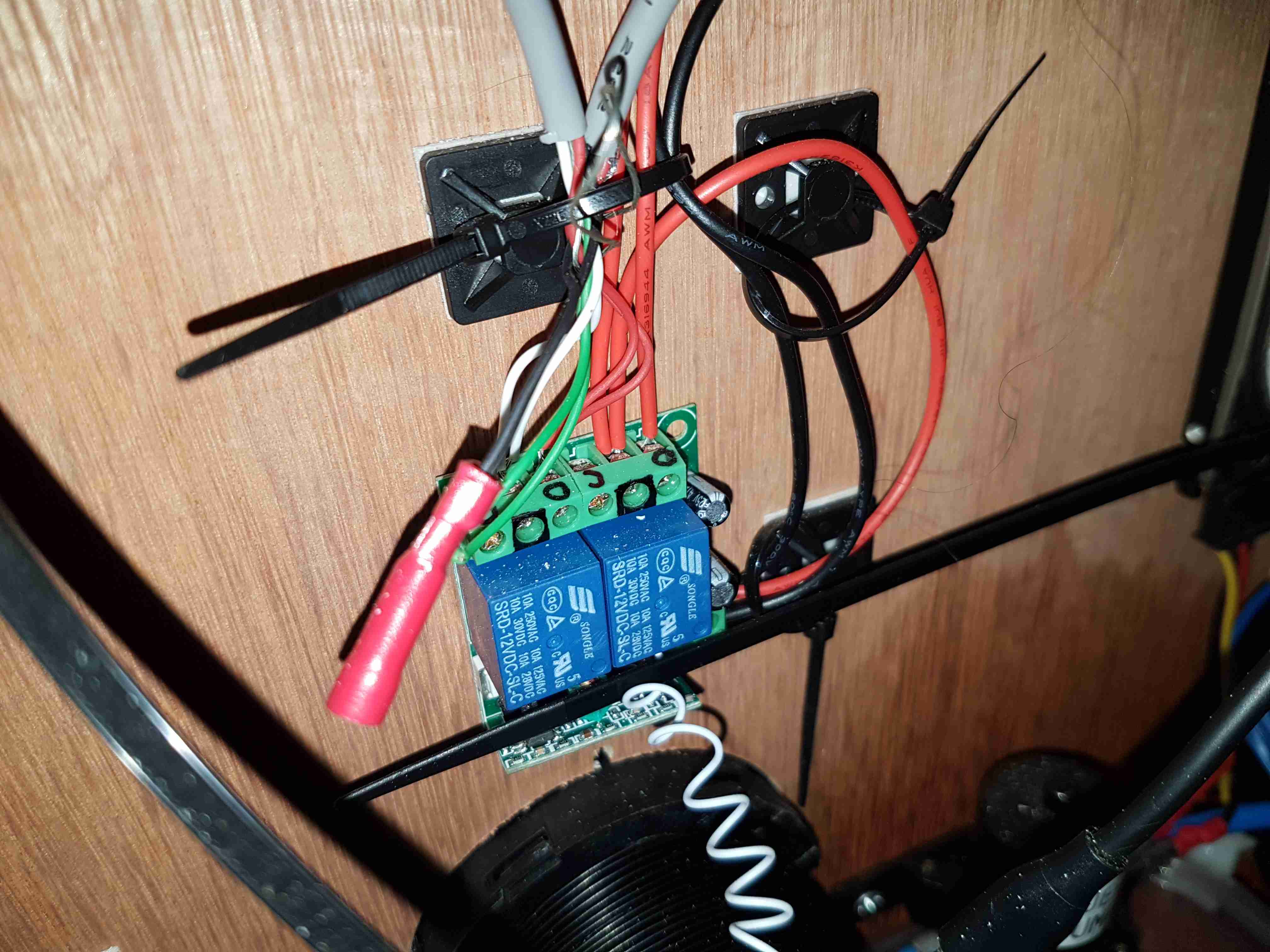
Remote Relays
There’s a small remote relay module here, for switching the DC output for lighting & the heater from afar. Very useful when it’s dark, since there’s no need to fumble around looking for a light switch. A car-style fob on my keyring instead.
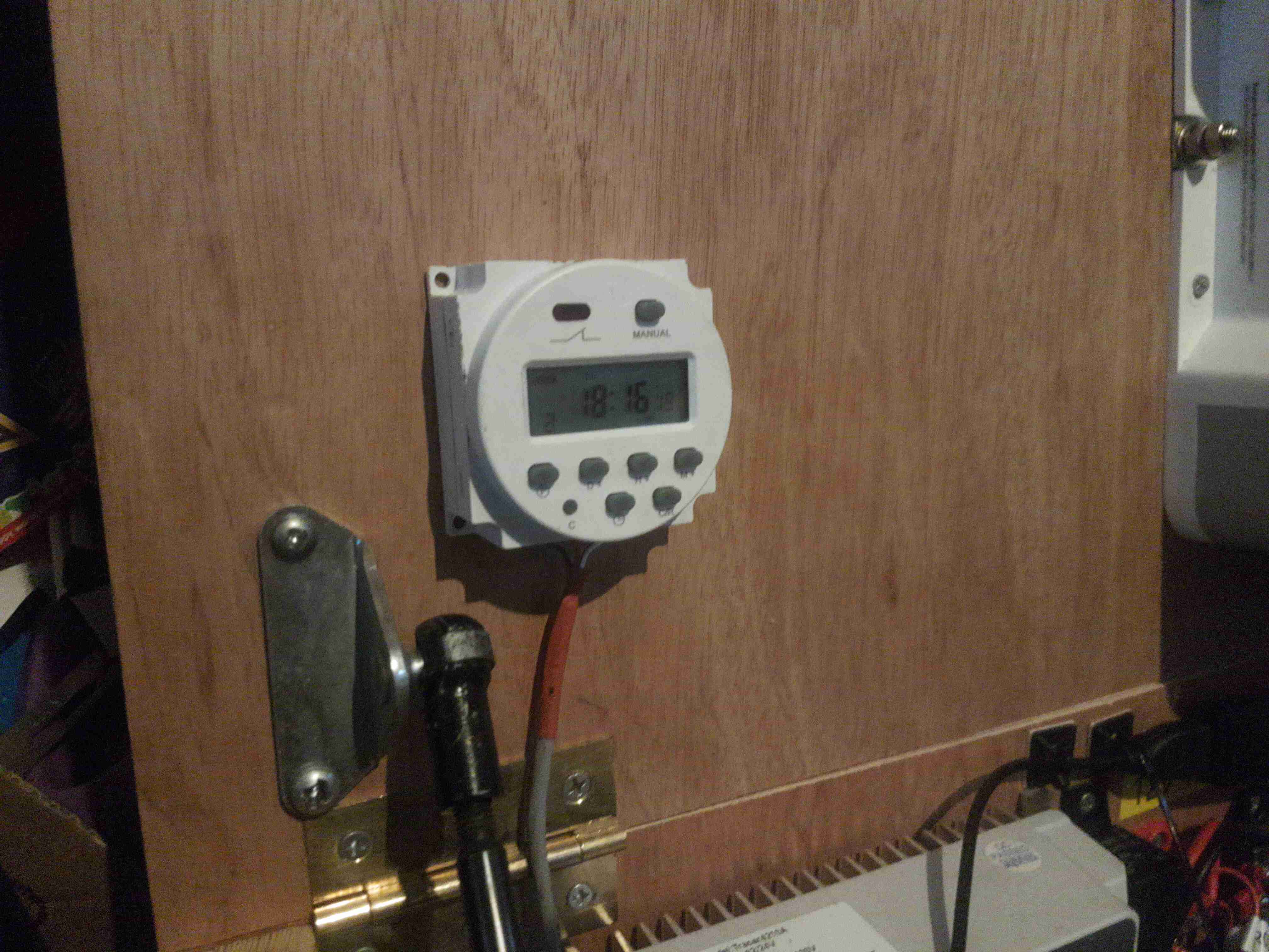
Heater Timer
Since the Eberspacher 701 controller I have is an ex-BT version, it’s very limited in it’s on time, a separate timeswitch is fitted to control the heater automatically. Being able to return to a nice warm tent is always a bonus.
Just to the left can be seen the top ball joint for the hydraulic cylinder that lifts the top of the box.
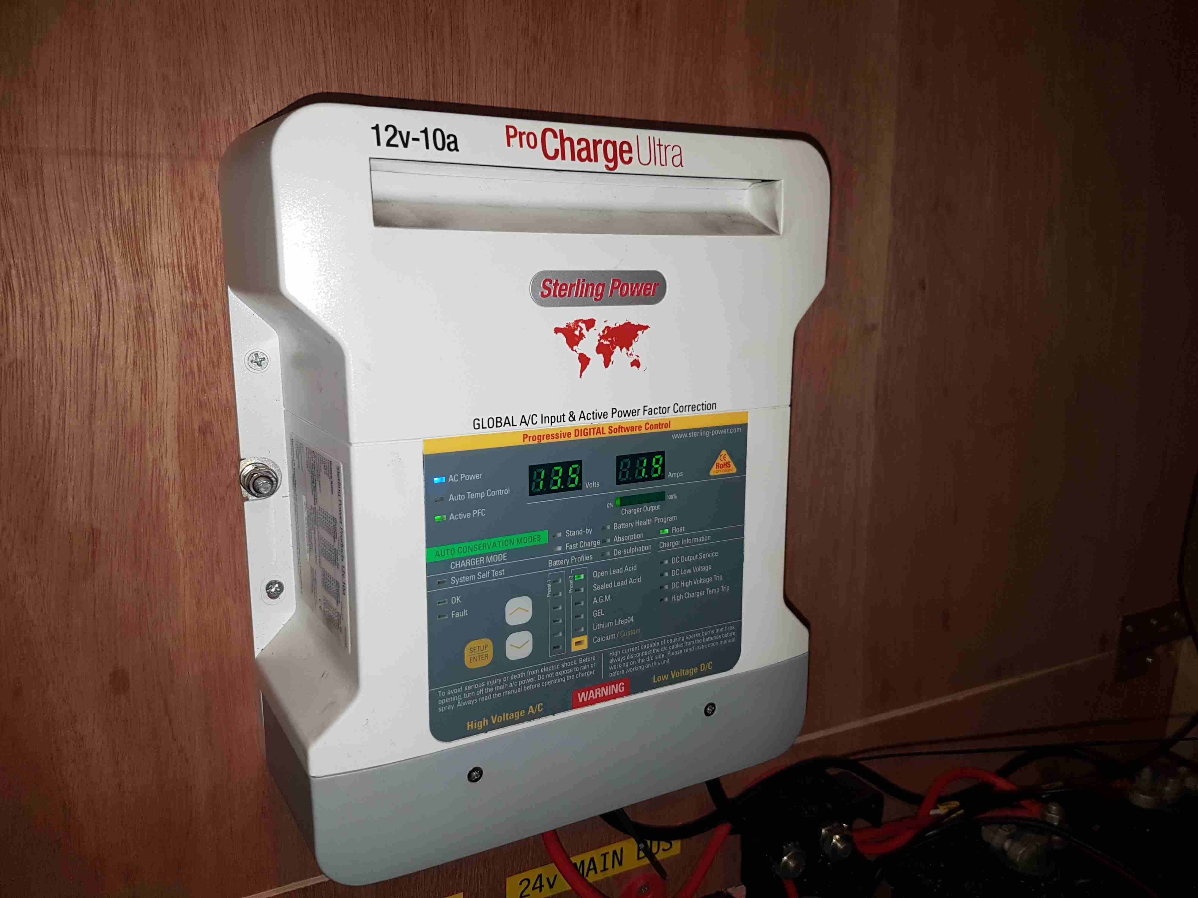
Battery Charger
The final large component is the battery charger. This unit will maintain the battery when the trolley isn’t being used.
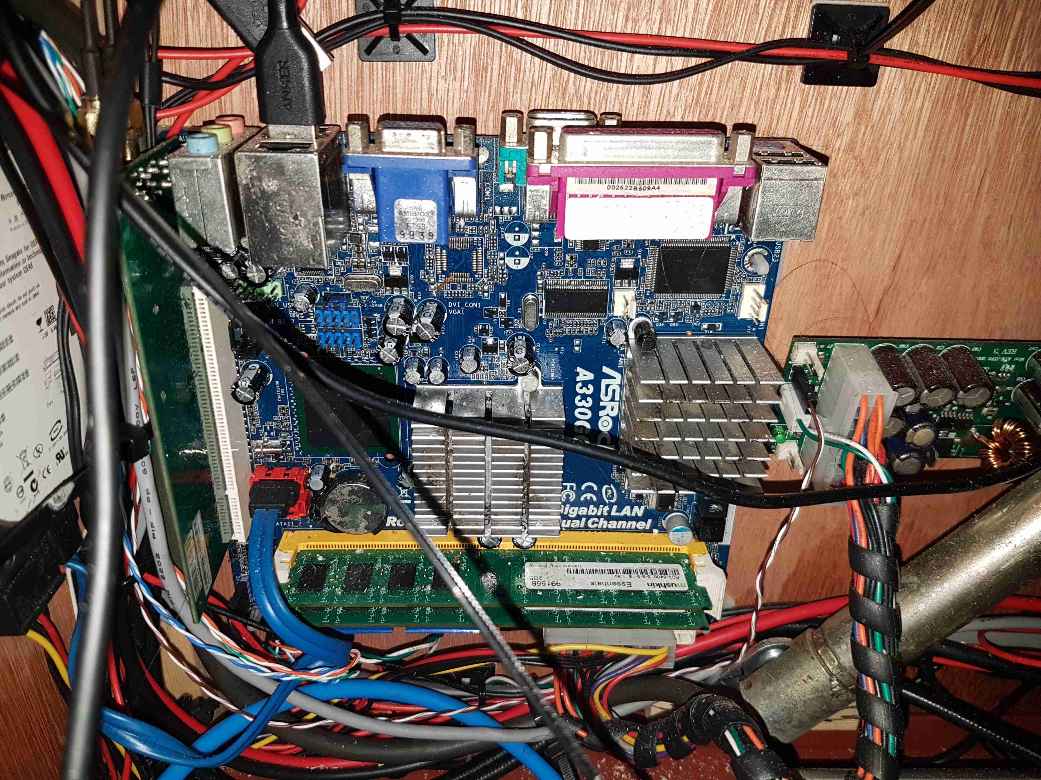
Router Motherboard
On the left side is the old Atom motherbaord used to provide a 4G router system. This unit gets it’s internet feed from a UMTS dongle & provides a local WiFi network for high speed connectivity. The bottom of the hydraulic cylinder is visible in the bottom right corner.
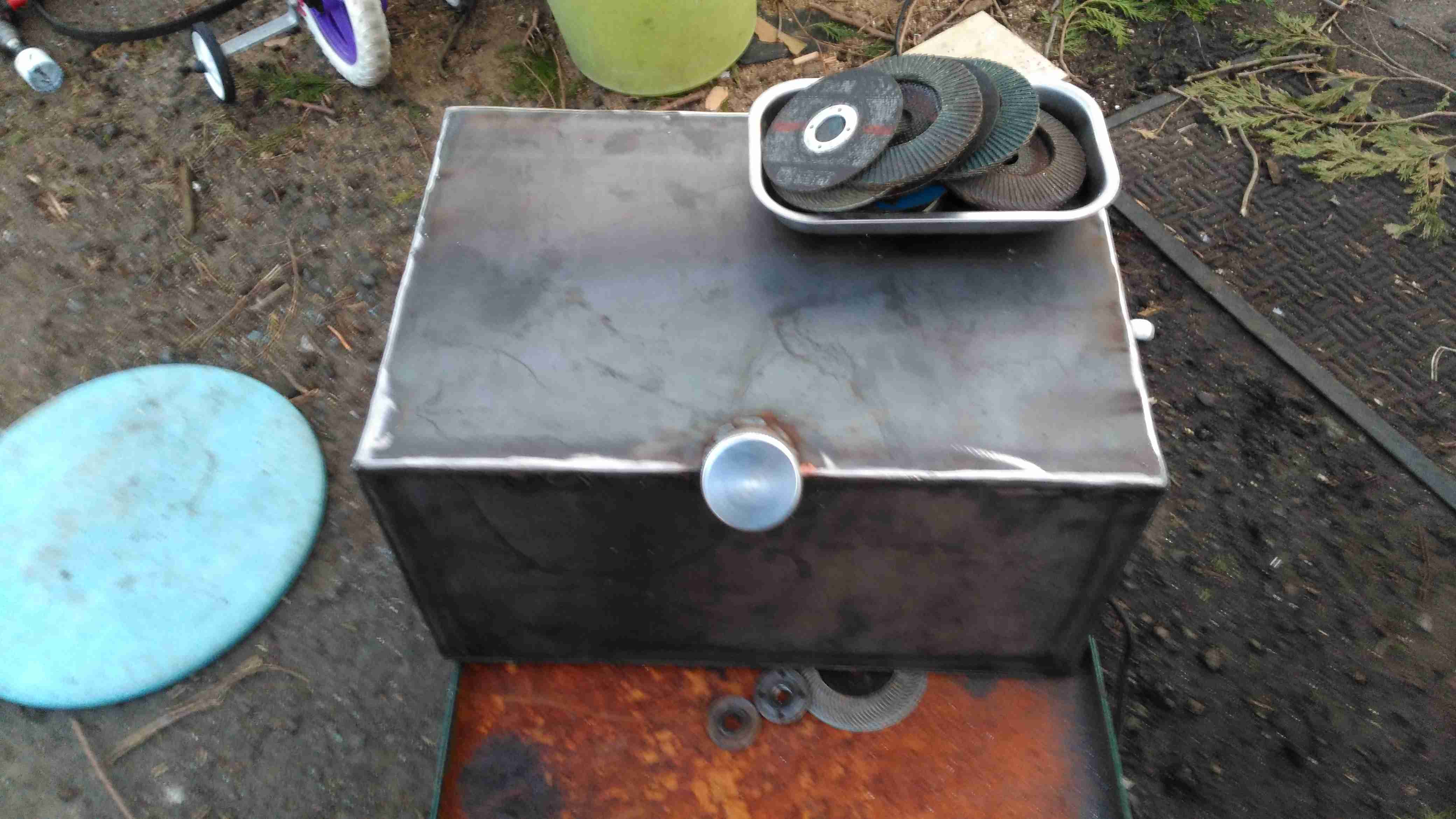
Fuel Tank Completed
Since the Eberspacher obviously needs fuel, a tank was required. In previous years I’ve used jerry cans for this purpose, but this trolley is supposed to have everything onboard, for less setup time. The tank is constructed from 3mm steel plate, MIG welded together at the seams to create a ~40L capacity. The filler neck is an eBay purchase in Stainless Steel. No photos of the tank being welded together, as I was aiming to beat sunset & it’s very difficult to operate a camera with welding gauntlets on 😉
The tank is the same width as the trolley frame, so some modification was required, having the wheels welded directly to the sides of the tank. This makes the track wider at the rear, increasing stability.
Fuel Dip Tubes
A quick view inside the tank through the level sender port shows the copper dip tubes for fuel supply to the heater, and an external fuel hose for my other fuel-powered camping gear. These tubes stop about 10mm from the bottom of the tank to stop any moisture or dirt from being drawn into the pumps.
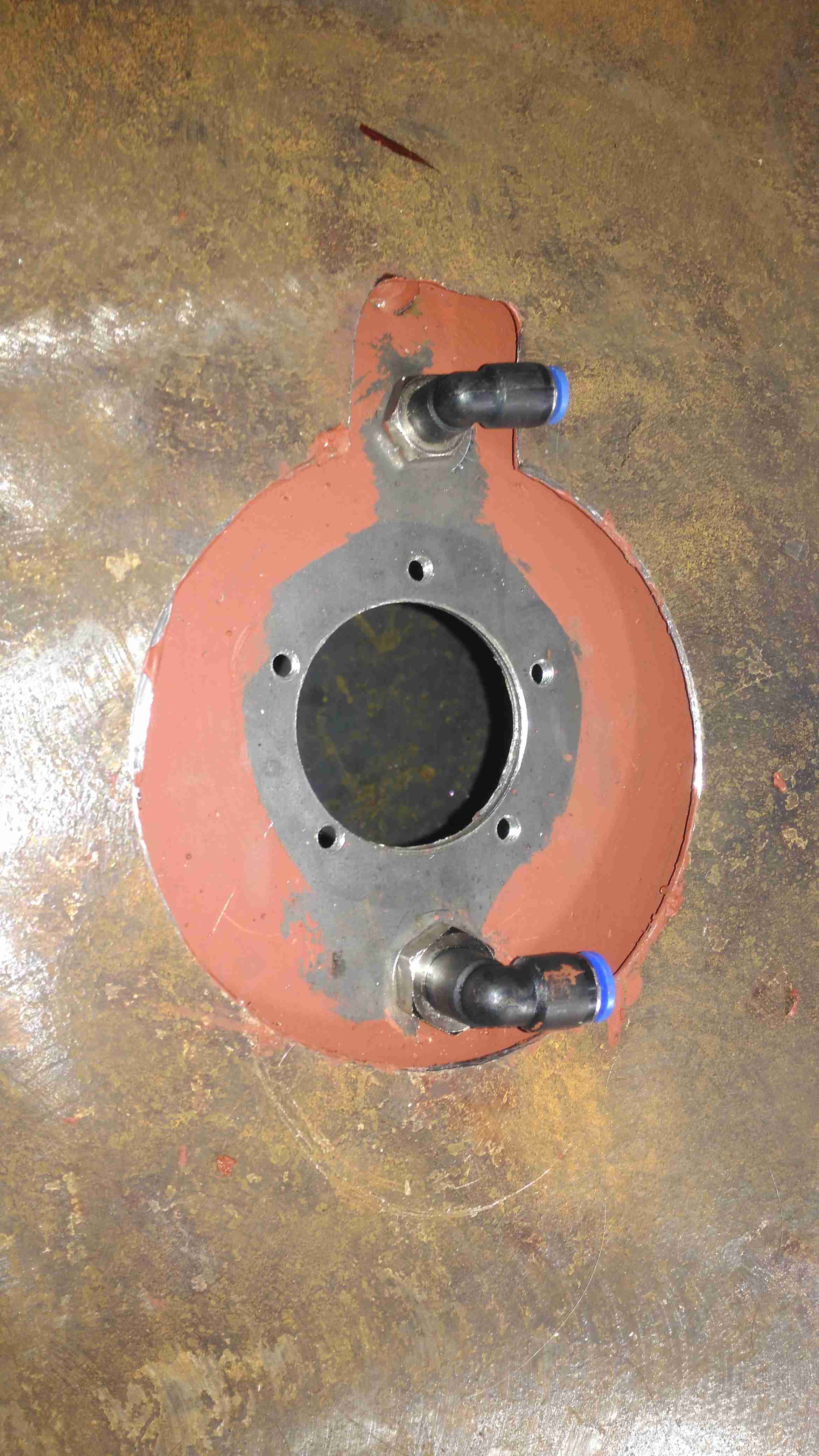
Fuel Feeds & Level Sender Port
The top of the tank is drilled for the fuel fittings & the level sender and has already been painted here. The 1mm base plate has yet to be painted.
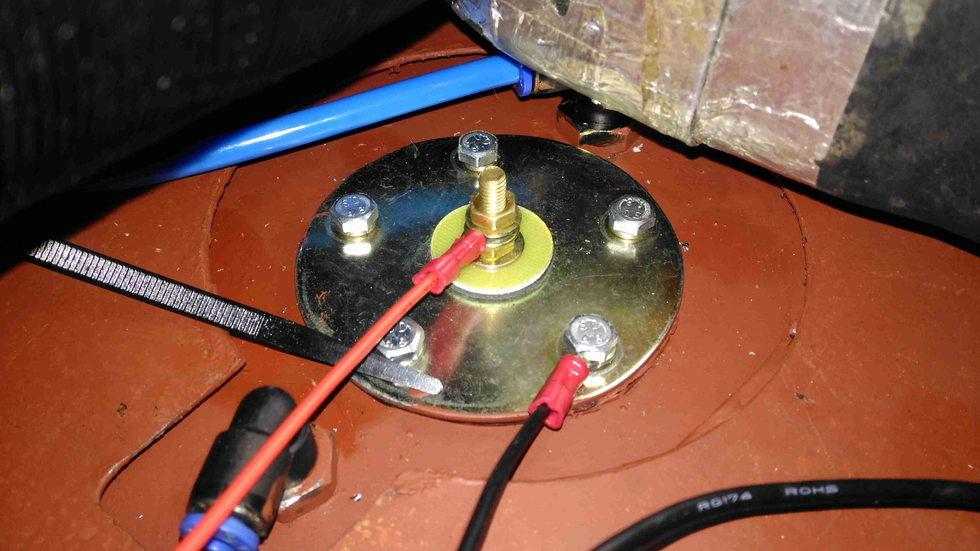
Level Sender Installed
Touching up the paint & fitting the sender is the last job for this part. The mesh bottom of the trolley has been replaced by a 1mm steel sheet to support the other parts, mainly the heater. Fuel lines are run in polyurethane tubing to the fuel pumps.
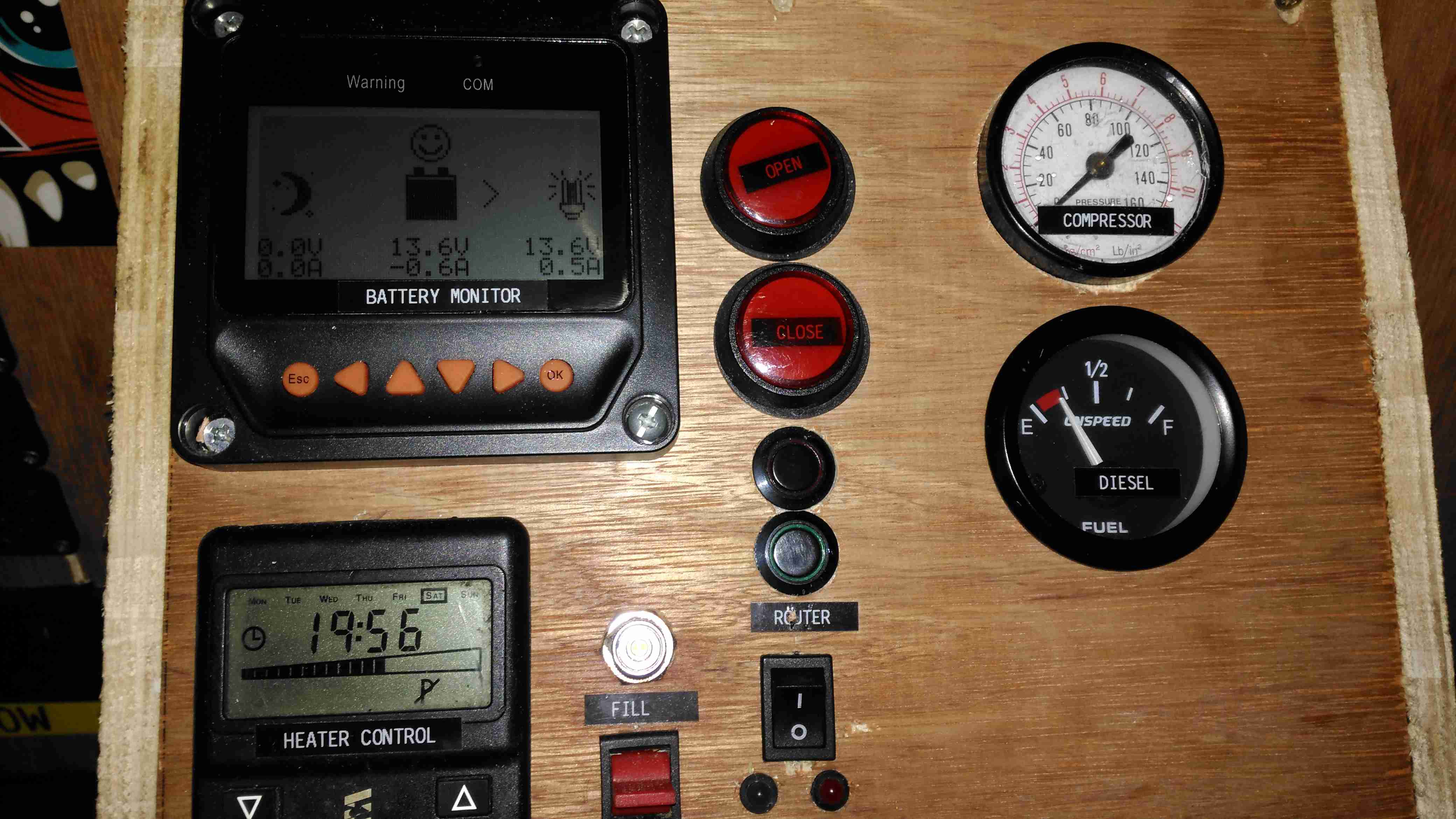
All the instruments & controls are on a single panel, with the Eberspacher thermostat, external fuelling port & pump switch, inverter control, the solar controller monitor panel, cover buttons, router controls, compressed air & fuel gauges.
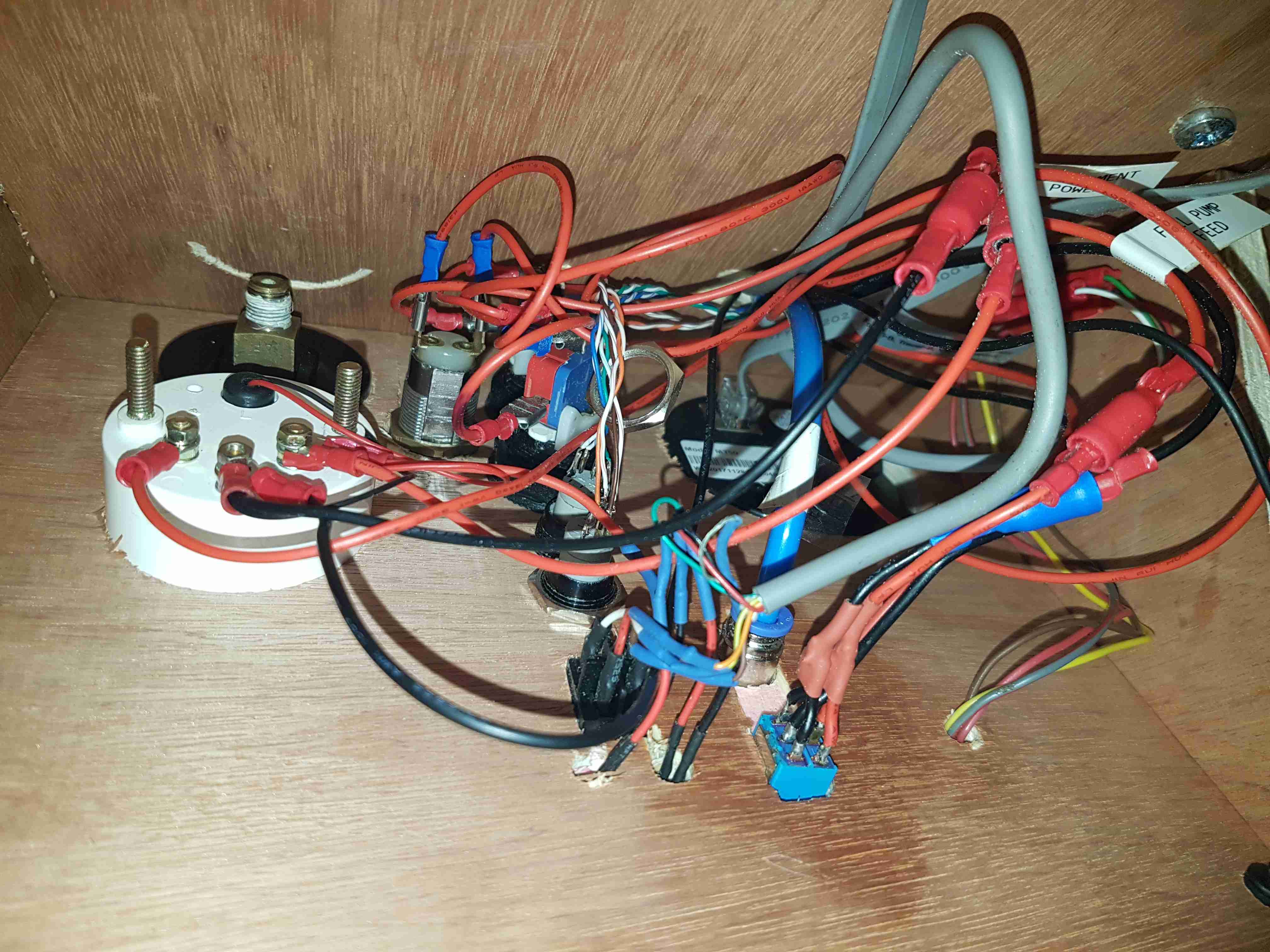
Panel Wiring
As is usual behind instrument panels, there’s a rat’s nest of wiring. There’s still the pressure gauge to connect up for the compressed air system, and the nut on one of the router buttons is such a tight fit I’ve not managed to get it into place yet.
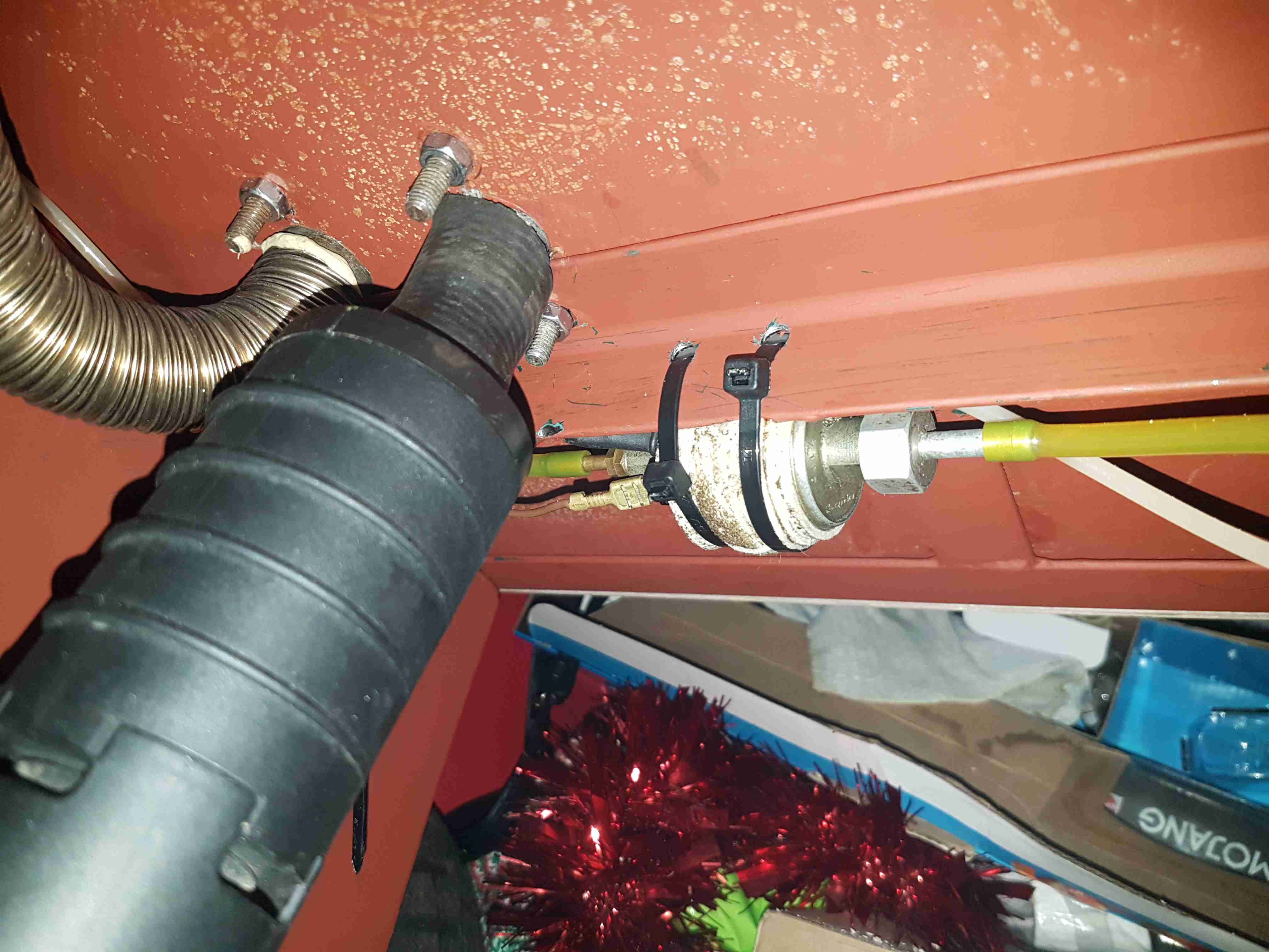
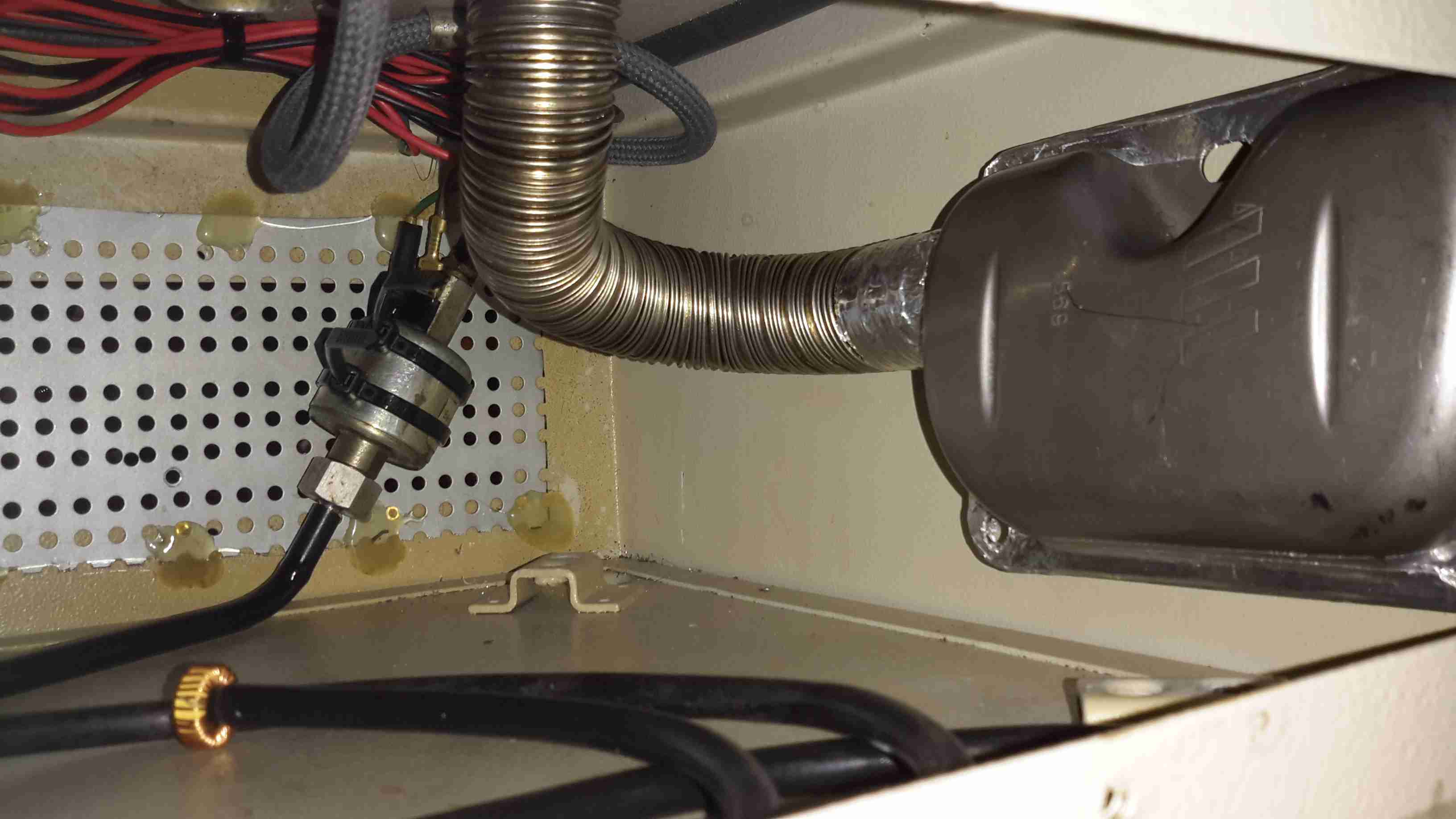
Eberspacher Fuel Pump
The support components for the Eberspacher heater are mounted underneath the baseplate, with the fuel dosing pump secured to a rail with a pair of cable ties, and some foam tape around to isolate the constant clicking noise these pumps create in operation. The large black cylinder is the combustion air intake silencer, with the stainless steel exhaust pipe to the left of that. Silencing these heaters is essential – they sound like a jet engine without anything to deaden the noise. Most of this is generated from the side-channel blower used in the burner.
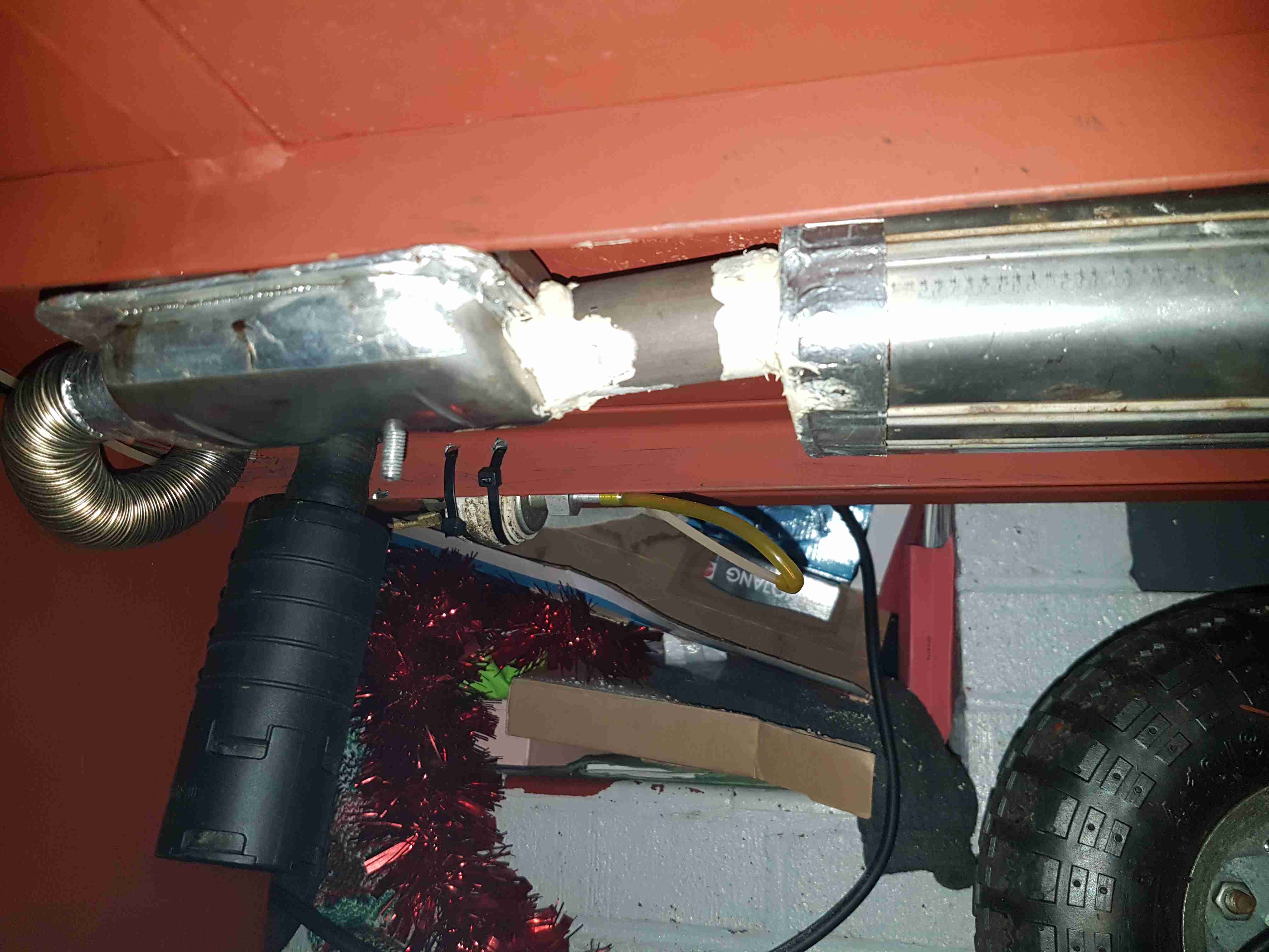
Eberspacher Exhaust
Bolted to the underside are a pair of exhaust silencers, one is an Eberspacher brand, the other is Webasto, since the latter type are better at reducing the exhaust noise. Connections are sealed with commerical exhaust assembly paste, the usual clamps supplied do not do a good enough job of stopping exhaust leaks.
Next update to come when I get the parts in for the air compressor system.
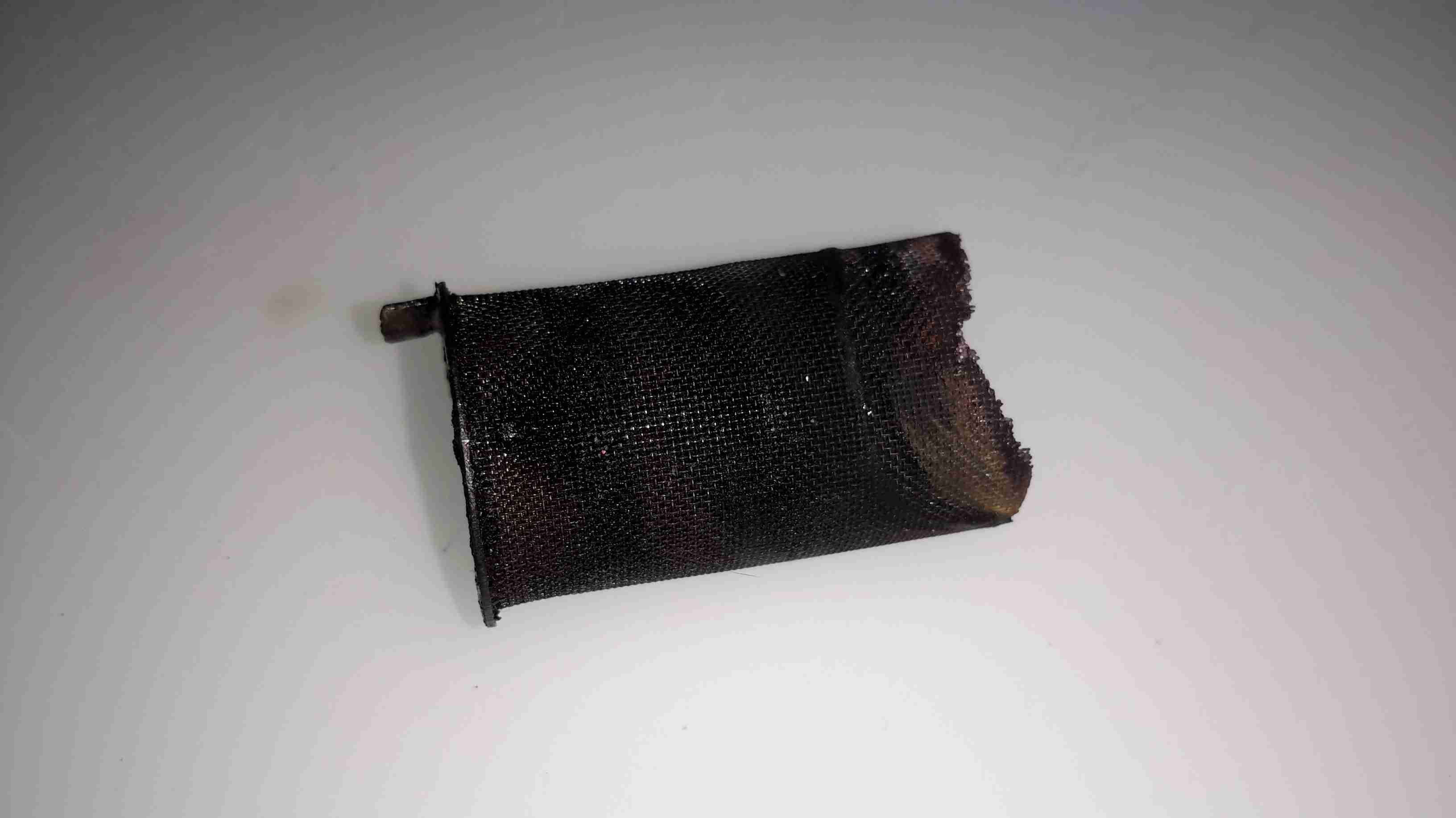
Some time ago I did a couple of posts on cheapening up the maintenance of Eberspacher hot air heaters by making the glow plug screens myself. Now one of my pieces of stainless mesh has been in the heater for nearly a year, and the heater is starting to get a bit smoky on a cold start. This is usually a sign that the screen isn’t allowing the fuel to vaporise quick enough for the glow plug to ignite the flame, because it’s becoming blocked. So far the heater has had about 150L of diesel through it with my DIY screen.
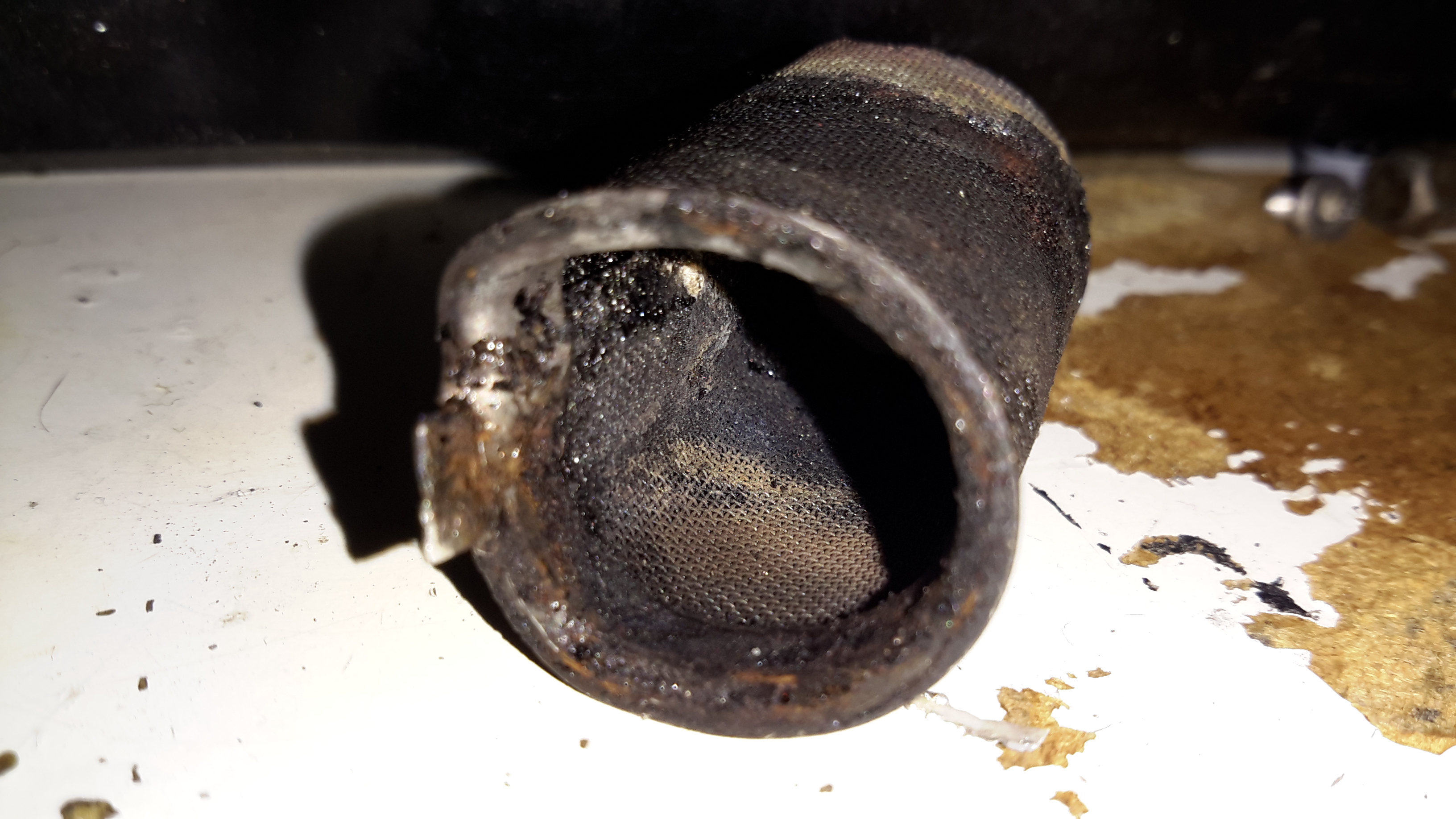
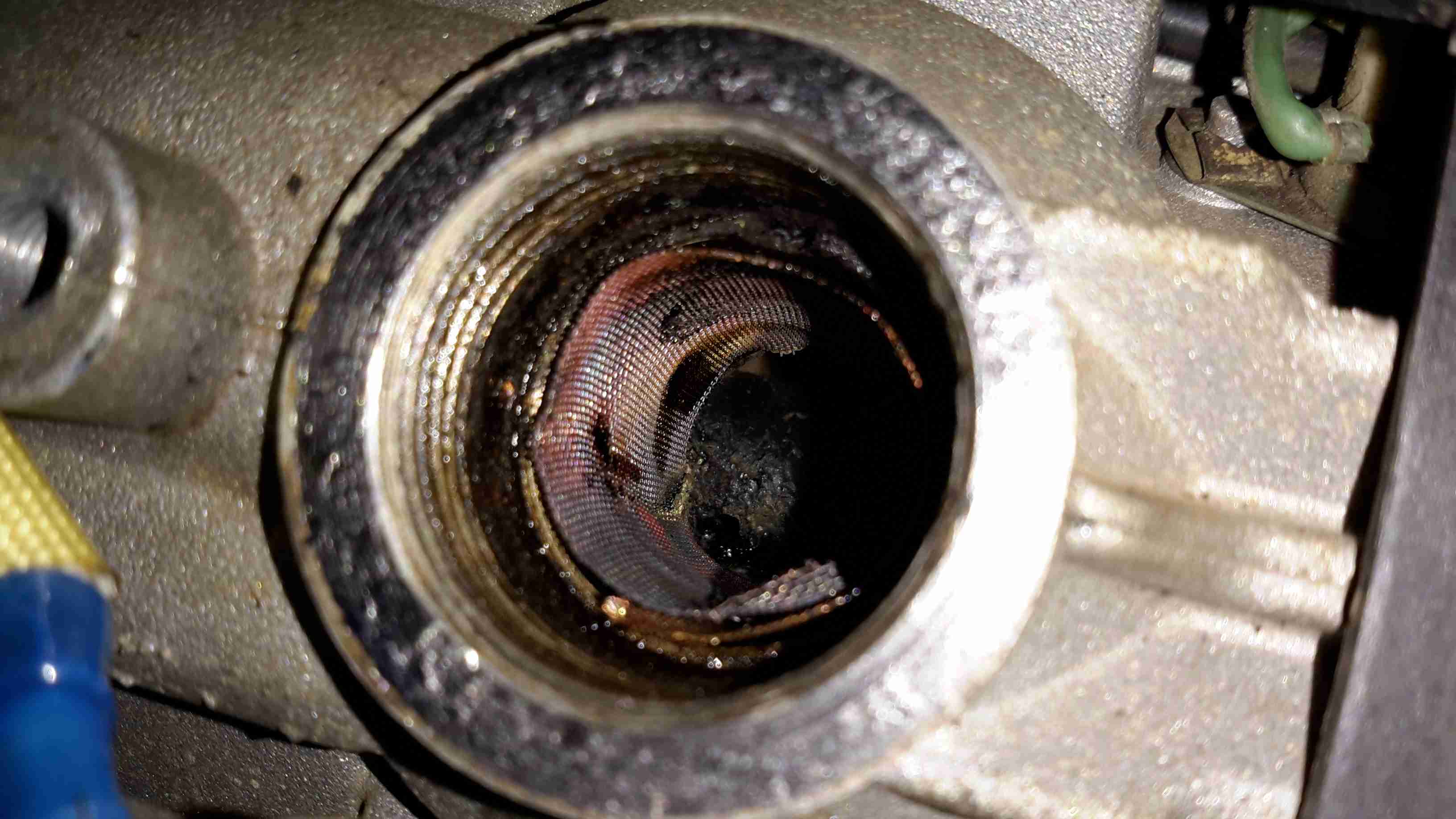
Old Screen
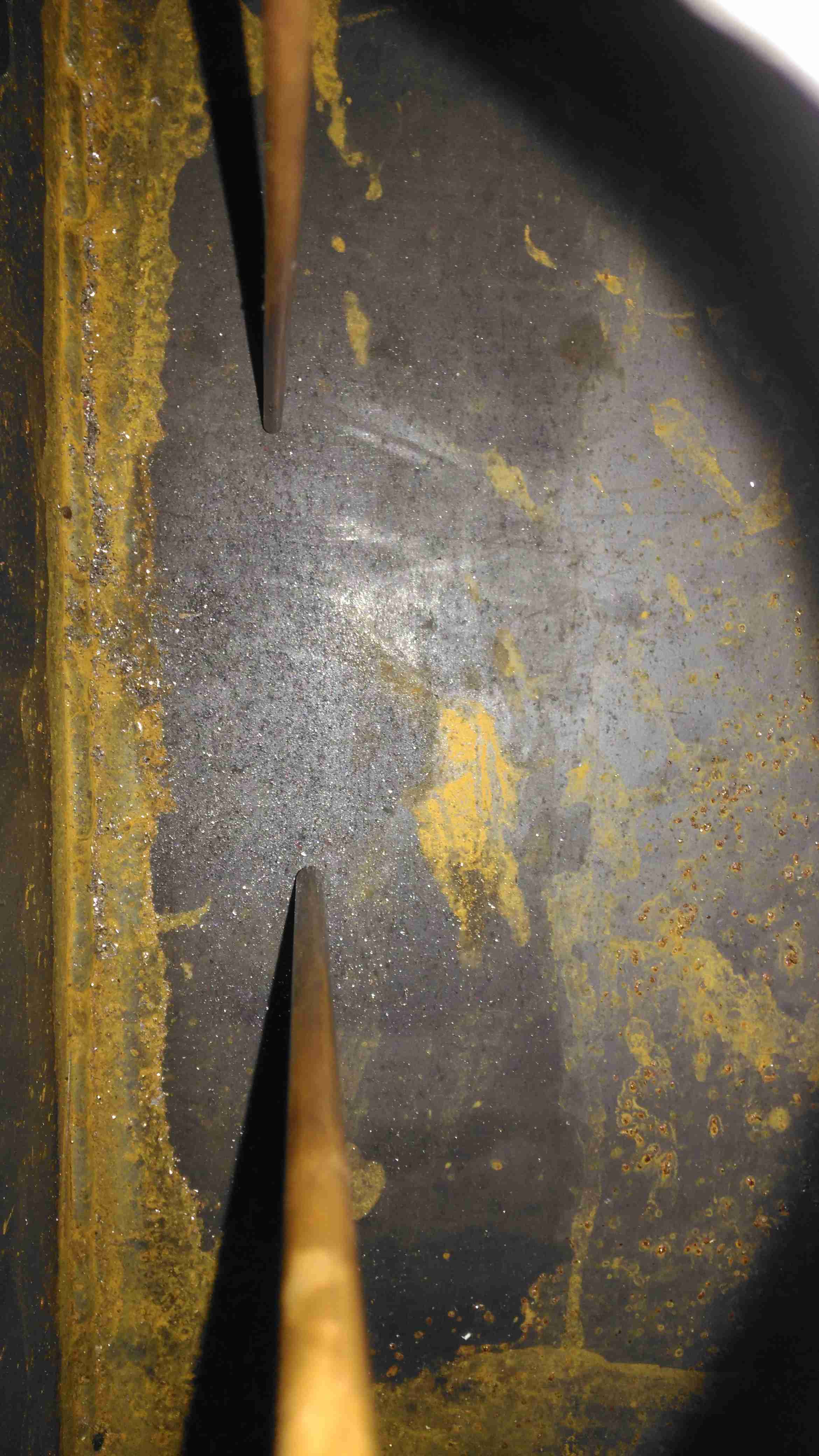
After removing the plug, here’s what’s left of the screen. The bottom end has completely disintegrated, but this is to be expected – OEM screens do the same thing as this end is exposed to the most heat in the burner. There’s quite a bit of coke buildup on the top end of the screen around the fuel nozzle, again this isn’t surprising, as this is the coolest part of the heater not all the heavier fractions of the diesel fuel have the chance to vaporise.
Innards
Looking further down into the mixing tube of the main burner, everything looks good. There’s a coating of soot in there, but no tar-like build up that would tell me the unit isn’t burning properly. Another advantage of making my own screens is that they’re much easier to extract from the hole once they’ve been in there for months. The OEM screens have a stainless ring spot welded to the mesh itself to hold it’s shape, and once there’s enough fuel residue built up the entire mess seizes in place, requiring some sharp pokey tools & some colourful language to remove. The single loop of mesh held in place by it’s own spring pressure is much easier to remove as it collapses easily.
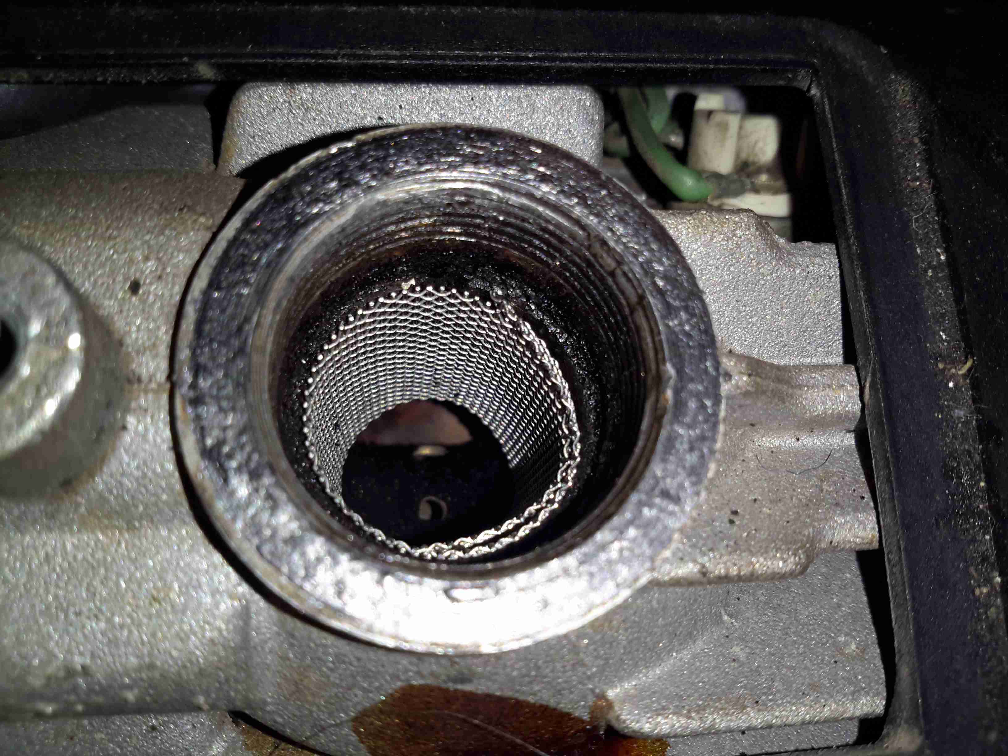
New 80 Mesh Screen
I’ve decided to change the mesh size of the screen while I’m in here, in this case to 80 mesh, which is much closer to the OEM screen size. There doesn’t seem to be much of a difference so far in either the starting or running capability of the heater, although the thicker wire of this screen might last longer before disintegrating at the burner end.
A while ago I posted about the glowplug screens in Eberspacher heaters, and making some DIY ones, as the OEM parts are hideously expensive for a piece of stainless mesh (£13).
Old Screen
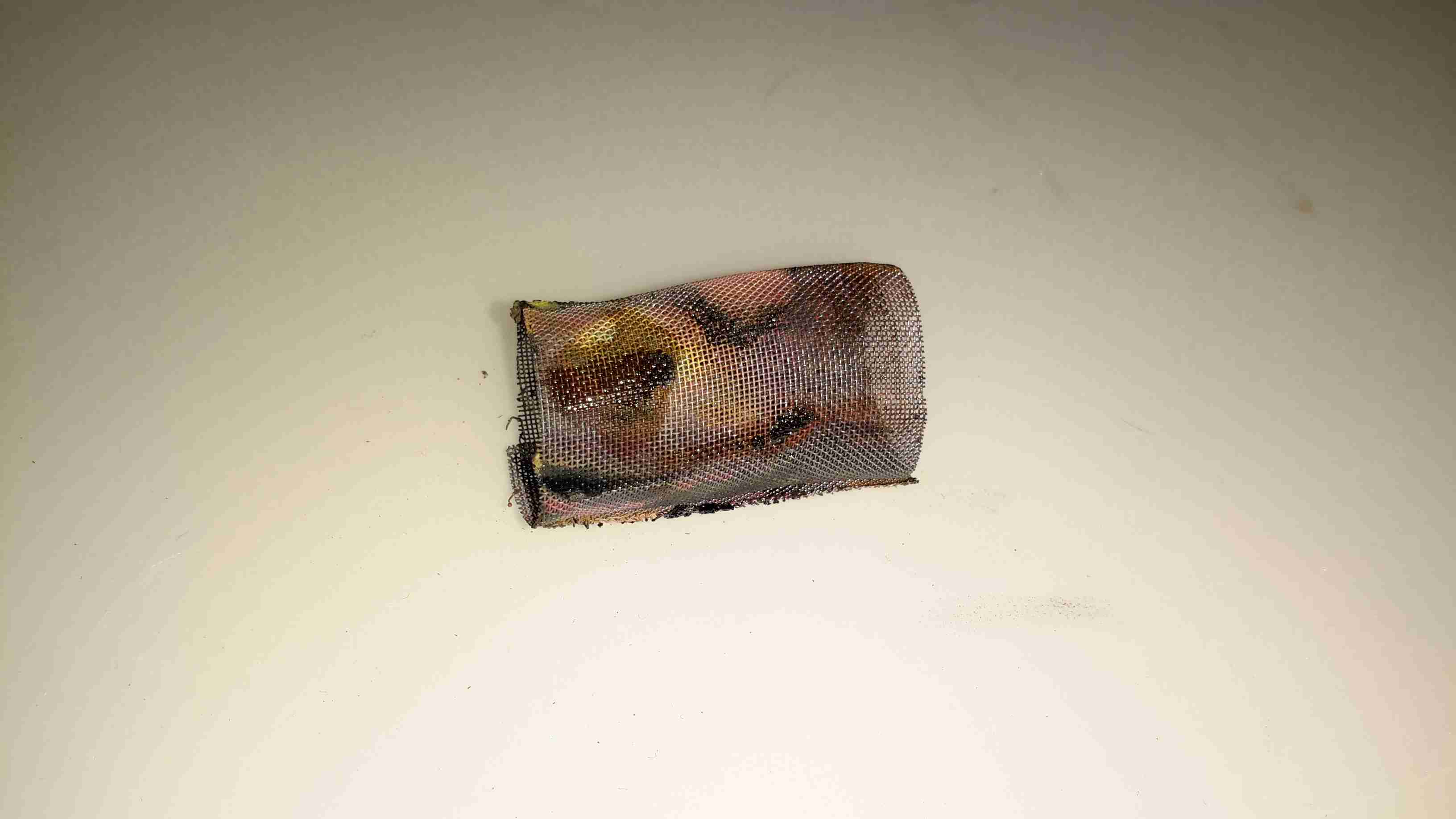
Above is the old factory screen that I extracted after only 5 gallons of diesel was run through it, it’s heavily clogged up with carbon & tar. The result of this clogging is a rather slow & smoky start of the heater & surging of the burner while at full power.
It wasn’t as badly stuck in the chamber as some I’ve removed, but extracting it still caused the steel ring to deform, this was after using a scalpel blade to scrape the carbon off the rim.
At the time I did some tests with some spare copper mesh I had to hand, but the problem with copper is that it’s very soft & malleable, so didn’t really hold it’s shape well enough. The factory screens are spot welded to keep them in shape, but as I don’t have a spot welder, I am relying on the mesh having a bit of springiness to keep it in place against the walls of the glowplug chamber.
eBay provided a piece of 120 mesh stainless steel mesh, 300mmx300mm for £8. It’s a bit finer than the stock stuff, but appears to work perfectly fine as long as there’s no gunk in the fuel to clog it up.
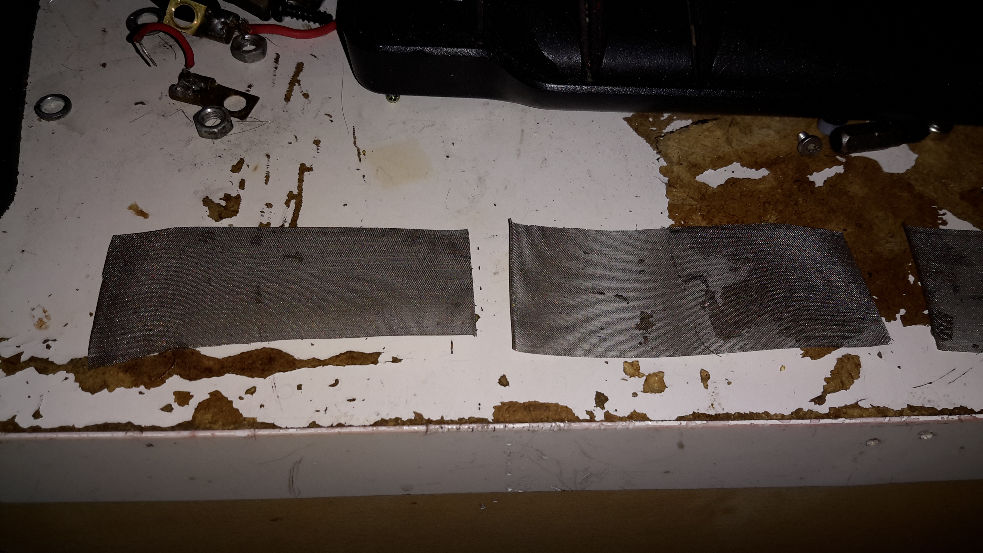
I cut a strip off the large piece, as wide as the OEM screen, about 32mm. This 300mm long strip is then cut into 4 pieces, each 75mm long. (it’s easily cut with scissors, but mind the stray wires on the edges! They’re very sharp & penetrate skin easily!).
Mesh Screen
These pieces are just the right size to form a complete loop in the glowplug chamber, and the stainless is springy enough so that it doesn’t deform & become loose.
The OEM screen is multiple turns of a more coarse mesh, but the finer mesh size of the screens I’m using means only one turn is required. Multiple turns would probably be too restrictive to fuel flow.
With one of these pieces of mesh in place, the heater starts instantly, without even a wisp of smoke from the exhaust. Burner surging is also eliminated. Even if the service life of my DIY replacement isn’t as long as an OEM screen, the low price for such a large number of replacements certainly offsets that disadvantage!
A piece of mesh from eBay would provide enough material for quite a lot of replacements, and probably more than the service life of the burner itself!
One of the central parts to the Eberspacher-type evaporative burner is the wire mesh screen that surrounds the glowplug, where the incoming fuel is heated to vapour before it’s blown into the combustion chamber & burned.
These screens, like glowplugs in the older heaters, are consumable parts and either get clogged with soot/tar or just eventually burn away.
The problem is that these parts (for what they are at least) are bloody expensive, so I’ve been looking to come up with something that can serve as a decent replacement for much lower cost.
OEM Screen
Here’s a slightly used screen from my D1LCC heater, as can be seen the lower edge is already burning away even after only a few hours use. This edge tends to burn as the screen projects into the combustion chamber by about 1/4″, so it’s exposed to higher temperatures there. The rest of the screen is covered by the alloy casting that holds the burner. The mesh itself is stainless steel, and looks like something between 120-150 mesh.
The mesh is wound 2-3 turns, and spot welded to hold everything together. I would imagine to give more surface area for fuel vaporization. An unfortunate side effect of this is that the screen is much more susceptible to clogging as the mesh size is effectively reduced.
This also makes them damn near impossible to clean, as the carbon deposits get stuck between the layers in the screen. Applying a blowtorch flame to the entire screen & heating it to orange heat (~1200°C) does burn most of the crap out of them. Running Paraffin/Kerosene as the fuel also makes for a much cleaner burn, extending life.
(Assuming of course that the screen can be removed without totally destroying it – in my experience after many hours of running they seize in place & require sharp implements, violence & much swearing to remove, in several pieces.)
I had some copper mesh spare from a previous project, around the correct mesh size, so I figured I’d cut a piece to the same size as the official mesh & give it a go in the heater.
DIY Screen
Here’s my single-layer DIY screen after a couple of hours operation in the heater. Ignition time doesn’t seem to be impaired, there’s no smoke from the exhaust, and it appears that it’s staying cleaner than an OEM screen, since the mesh size is a little larger. I’ll have to monitor the situation & see how long these last, but if it’s anything close to the OEM screen life it’ll make maintenance much cheaper.
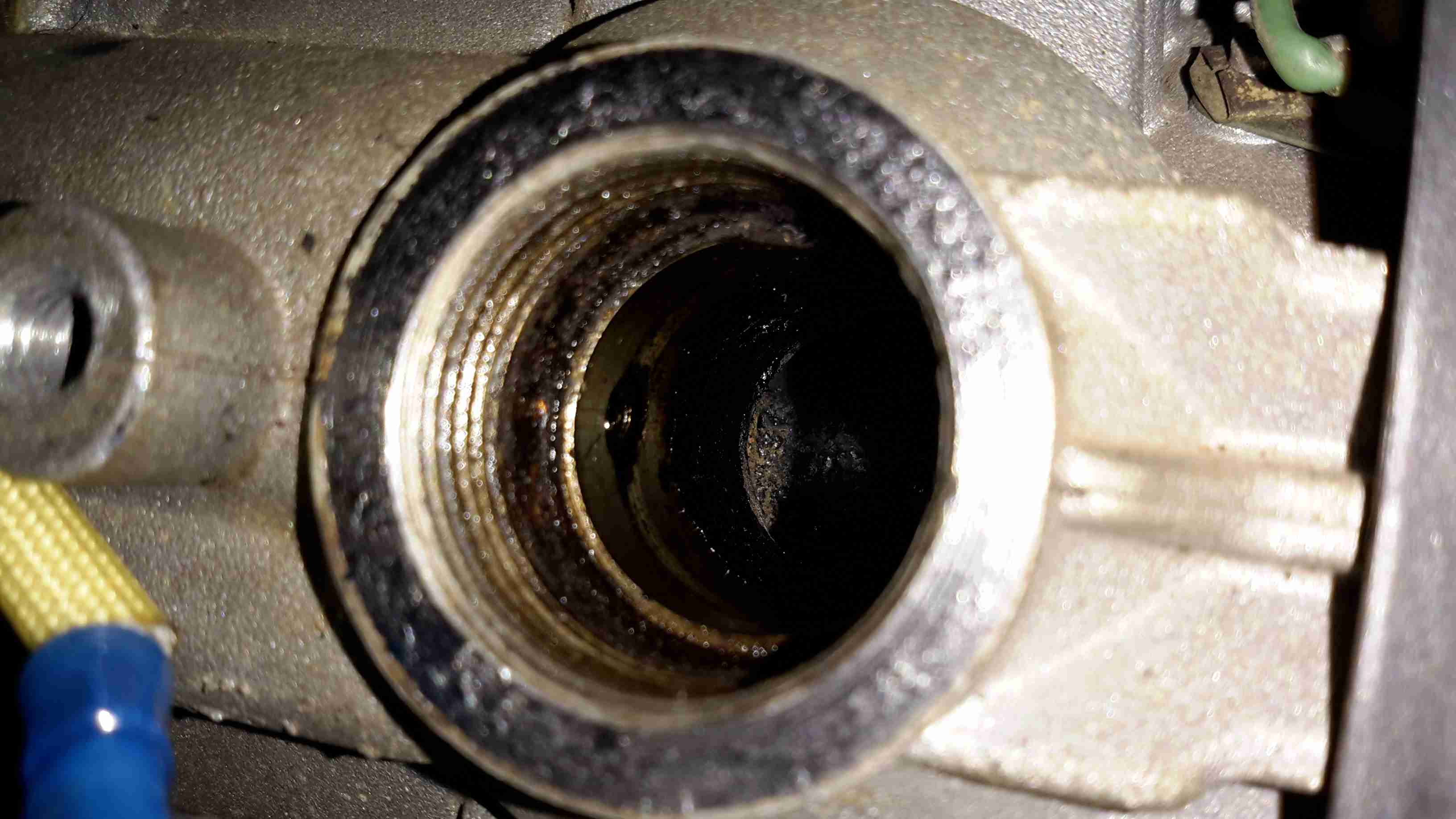
Fuel Inlet
This is the opening that holds the glowplug & it’s screen. The fuel inlet can be seen on the left wall of the chamber, with a circular groove that feeds fuel onto the screen in operation.
DIY Screen Fitted
And here’s the DIY screen in place, it’s obviously not as good a fit as the OEM version, but it’s sufficient to do the job!
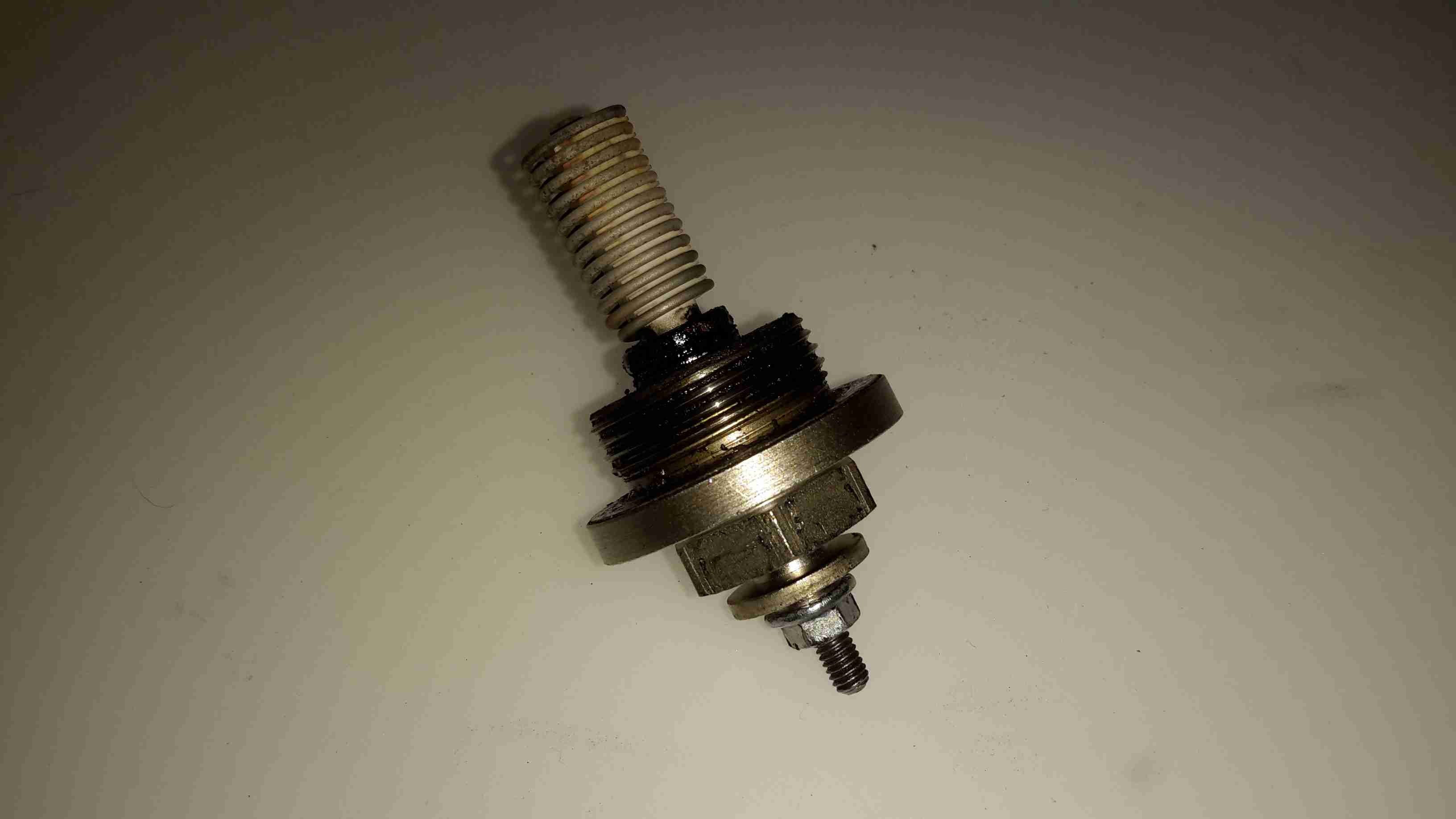
Glowplug
Finally, here’s the glowplug itself. Possibly the beefiest plug I’ve ever seen, even in large diesel engines.
I go camping on a regular basis here in the UK, and often even in summer it’s horribly cold at night in a field somewhere in the middle of Leicestershire. This doesn’t go too well with my severe aversion to being cold.
For the past several years I’ve used a Tilley lamp for some heat & light while at festivals & general camping, but it’s heat output is less than stellar when used in a 6-man tent.
An Eberspacher diesel heater was what was required for the job. Above is the unit as it’s built at the moment – I’ve used an old D1LCC 1.8kW heater that was recently decommissioned from nb Tanya Louise, as it’s getting a bit funny about what kind of fuel it’ll run on in it’s old age. It’ll work perfectly well on kerosene though – a fuel I already take with me camping for the Tilley.
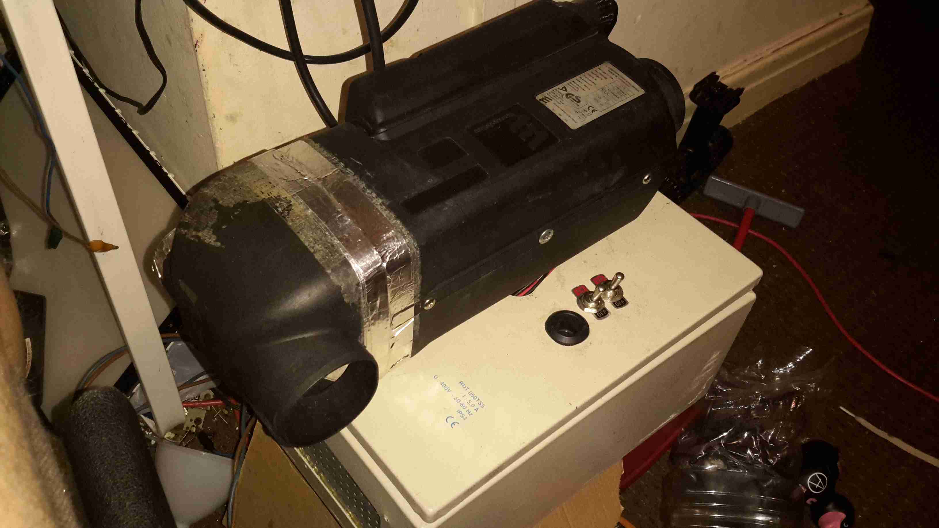
It’s mounted on a base box, which is a repurposed steel electrical junction box that saw a previous life containing a 3-phase fan motor controller.
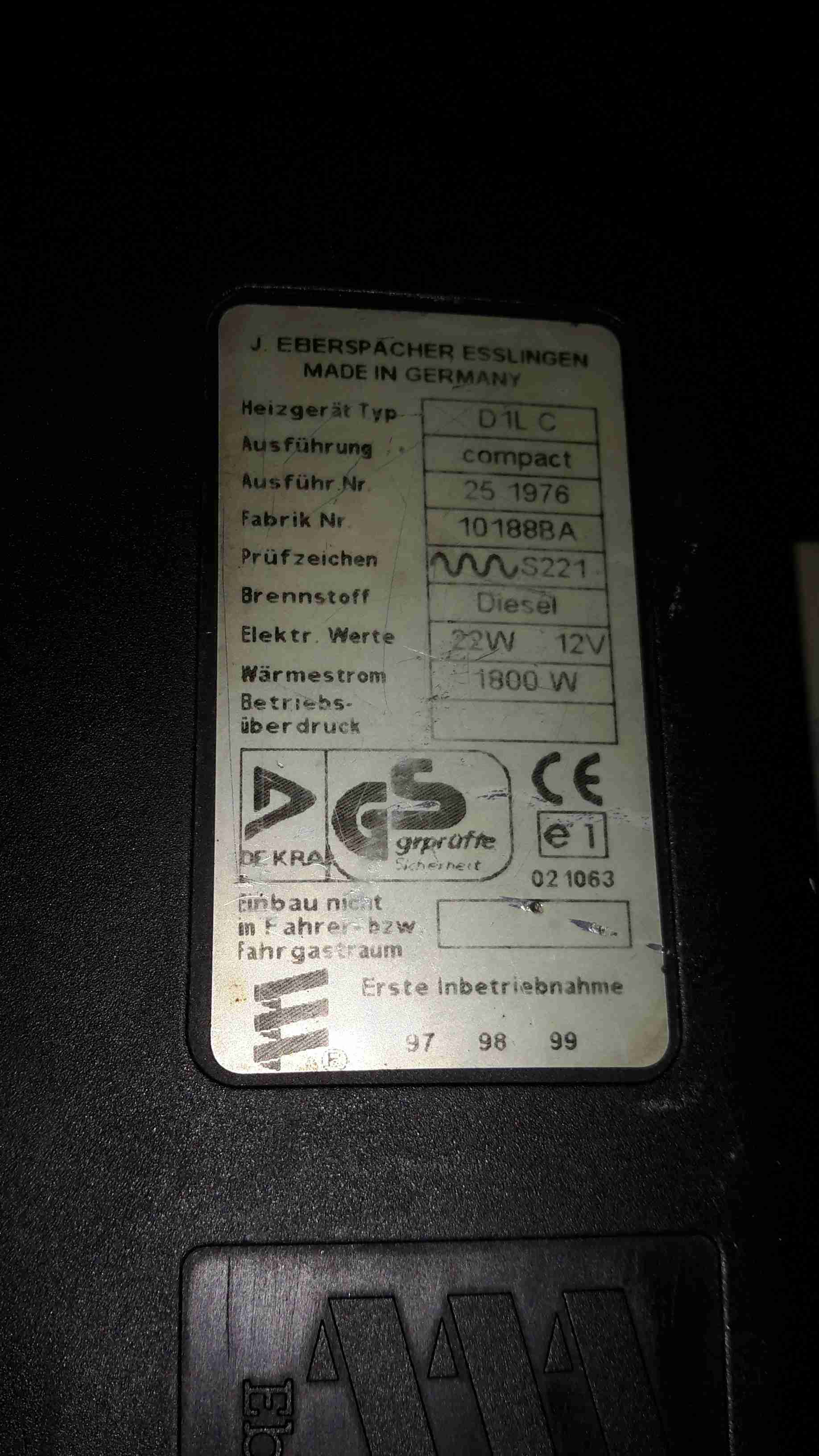
Data Plate
Here’s the info on the heater unit itself. Drawing 22W of power at 12v I’ll be getting 1.8kW of heat output – sounds good to me.
Box Internals
Here’s a view into the base box before the circulation fans were fitted, in early prototype stage. I used a small toroid as a clunk on the end of the rubber fuel line 😉
Support Components
After a few bits from the Great eBay arrived, here’s the internals of the base unit at present. The fuel tank is a repurposed 2L fridge water container – made of tough HDPE so it’s fuel resistant.
The fuel pump is mounted on the left side next to the tank – having been wrapped in some foam to deaden the continual ticking noise it creates. The exhaust & it’s silencer are mounted at the rear, the silencer being retained by a surplus rubber shock mount. Luckily the exhaust systems on these heaters don’t get particularly hot, so the rubber doesn’t melt.
The exhaust outlet is routed through the frame, to be attached to an external hose. I don’t want combustion gases in the tent with me!
Standard Eberspacher silencers also aren’t gas-tight from the factory – they’re designed to be used in the open on the underframe of a vehicle, so I’ve covered all the seams in aluminium tape to make the system airtight.
Ventilation
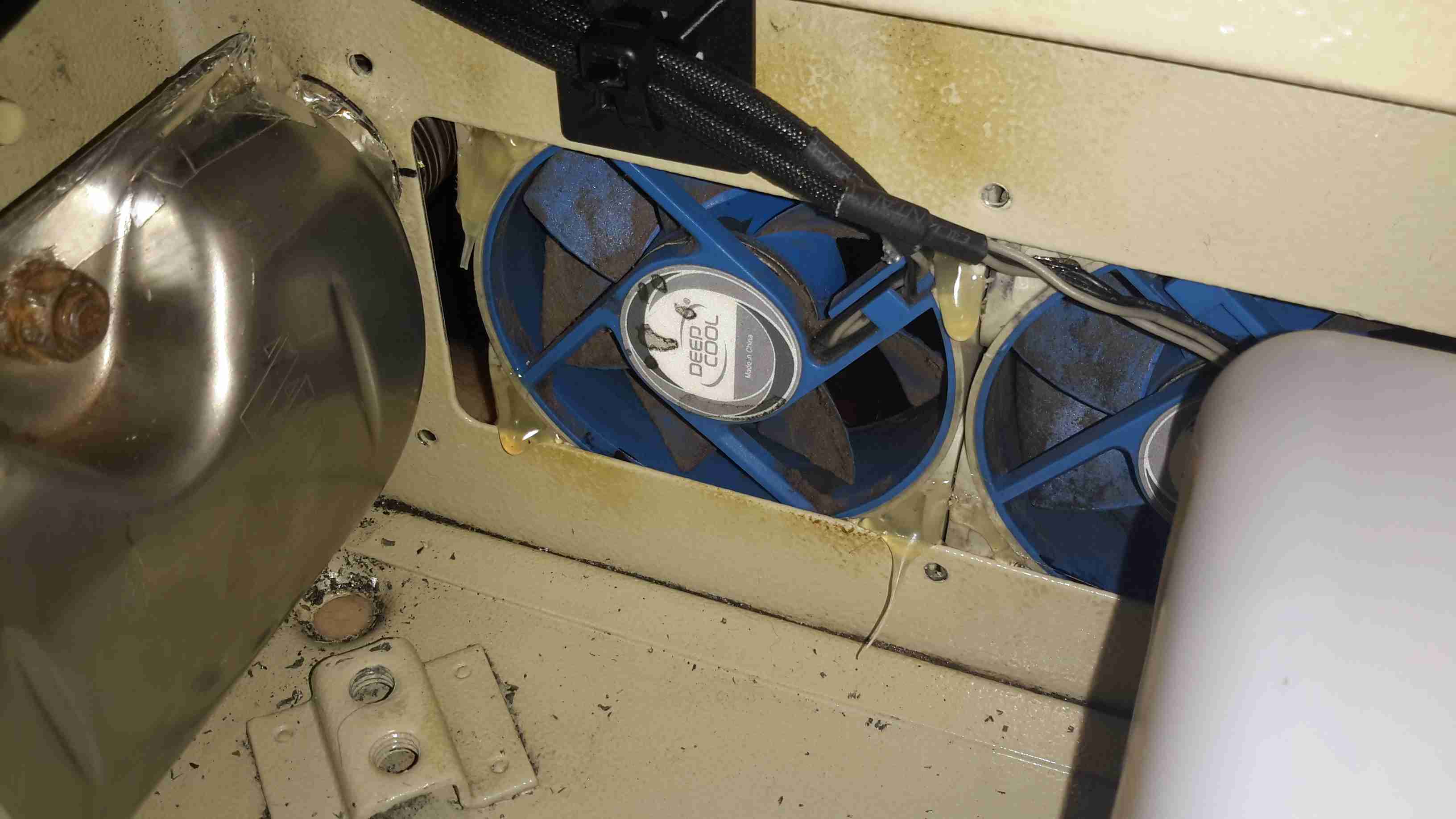
To make sure that the support components don’t get overheated with the exhaust being in such close proximity, and to pull a little more heat out of the system, a pair of slow-running 80mm fans has been fitted to the end of the box. These blow enough air through to give a nice warm breeze from the vents on the other end of the base.
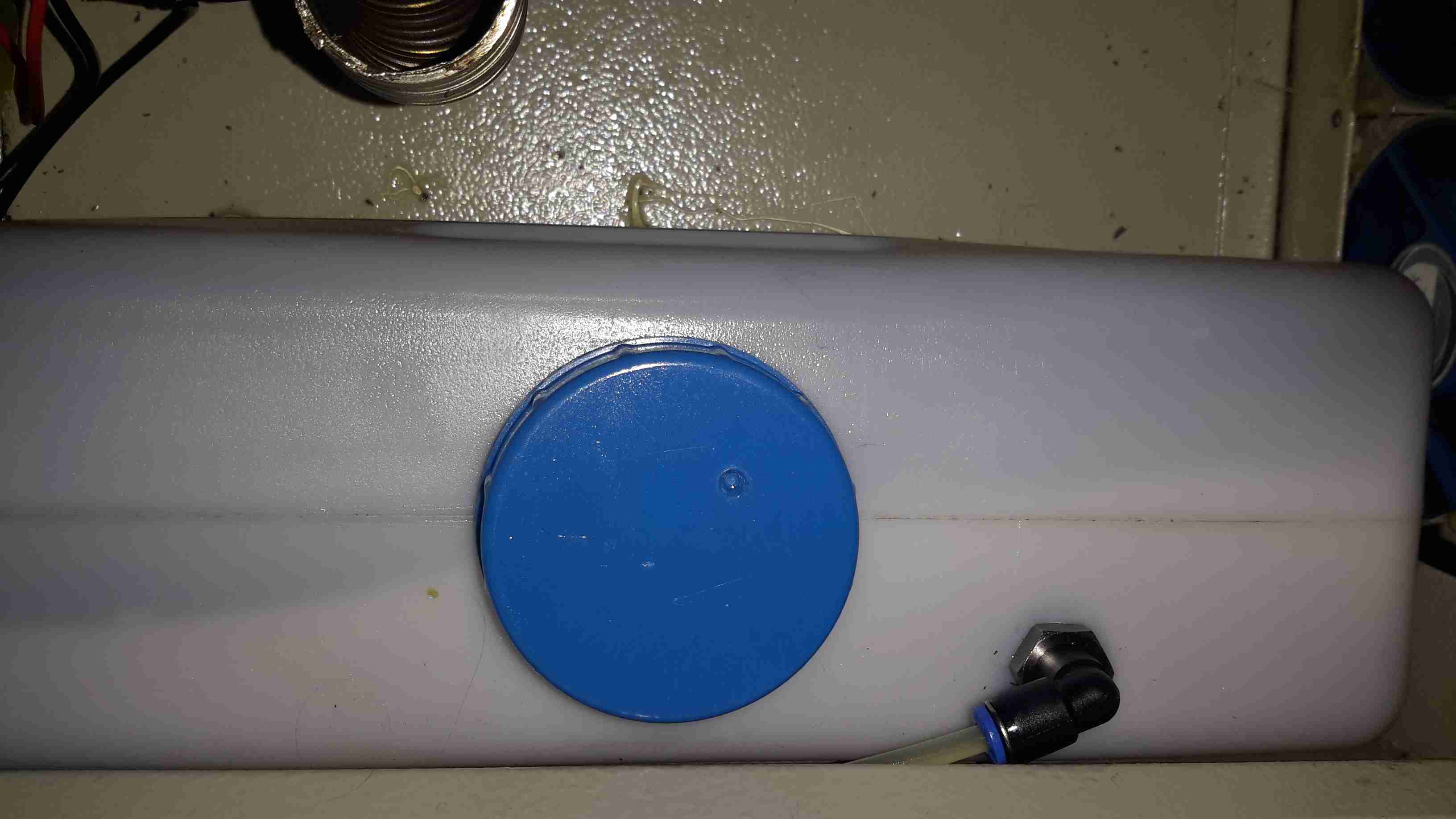
Fuel Tank
The tank I’ve used just so happened to be the perfect size to fit into the base box, and to tap the fuel off a bulkhead fitting was put into the top of the tank, with a dip tube on the other side. The fuel line itself is tiny – only 4mm.
If the specifications from Eberspacher are to be believed, 2L of fuel on board will allow the system to run for about 8 hours on full power, or 16 hours on minimum power.
Being inside the base, refuelling is a little awkward at the moment, the heater has to completely cool before the exhaust can be detached without receiving a burn, so I’ll be building in a fuel transfer system from an external jerry can later to automate the process – this will also help to avoid messy fuel spills.
More to come when the rest of the system is worked out!
73s for now!
Tip Jar
If you’ve found my content useful, please consider leaving a donation by clicking the Tip Jar below!
All collected funds go towards new content & the costs of keeping the server online.