Posted on Leave a comment

Melles-Griot 05-LHR-088 Helium-Neon Laser

Beam
05-LHR-088-097 Tube
05-LHR-088-097 Tube

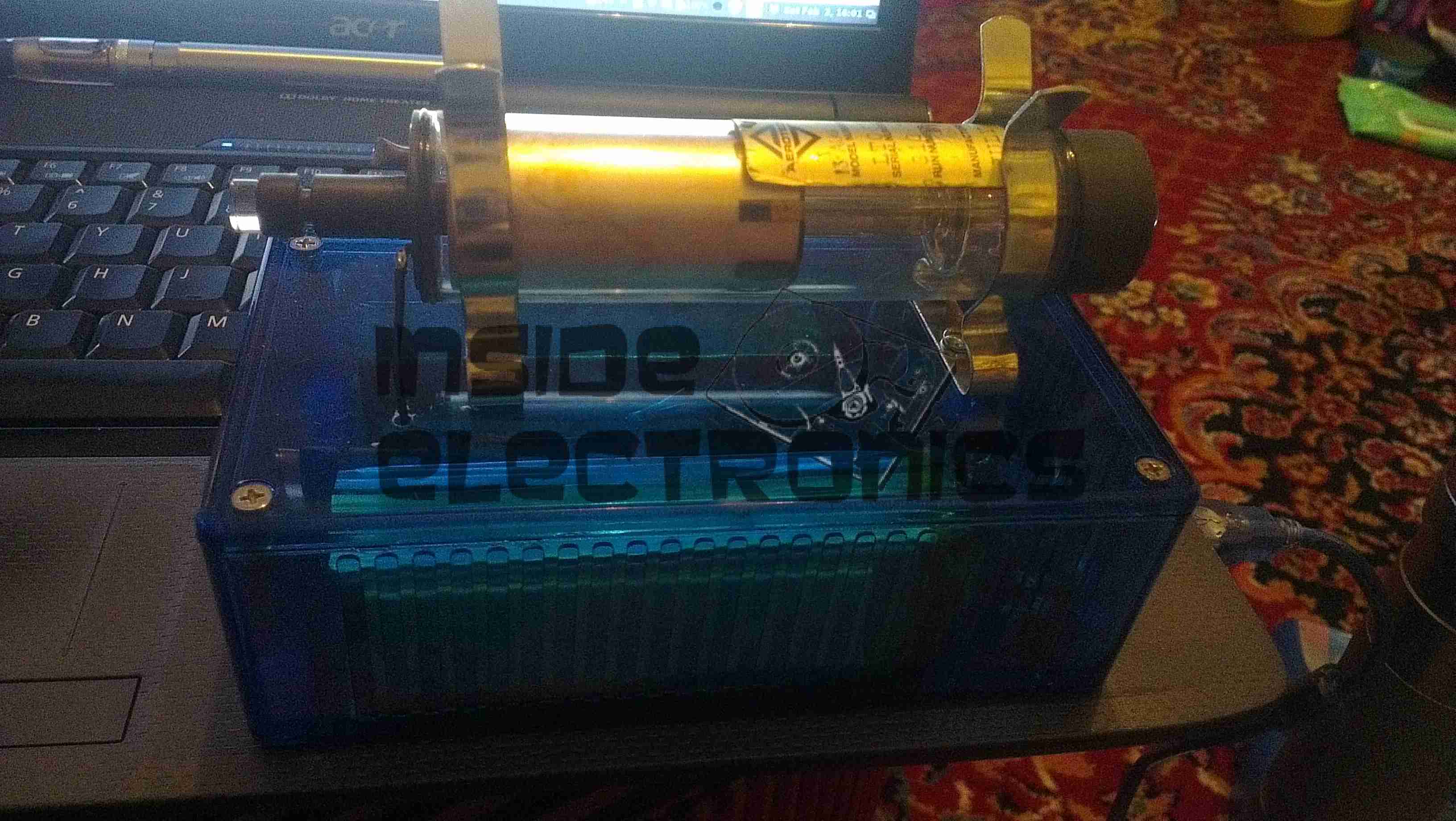
Here’s another Helium-Neon to add to the electric glassware collection, a 2mW Melles-Griot 05-LHR-088 which I pulled from the optical assembly from an ancient Spectra-Physics SP910 laser level. This tube is a standard Red 632.8nm with Random beam polarisation. The specifications are in the table below:

Minimum Optical Powere/2 Beam DiameterDivergencec/2L Mode SpacingSupply Opr/Start VoltsNominal CurrentDiameter/Length
2mW0.63mm1.4mR641MHz1.82/10kV4.5mA29/241mm
Tube Label
Tube Label

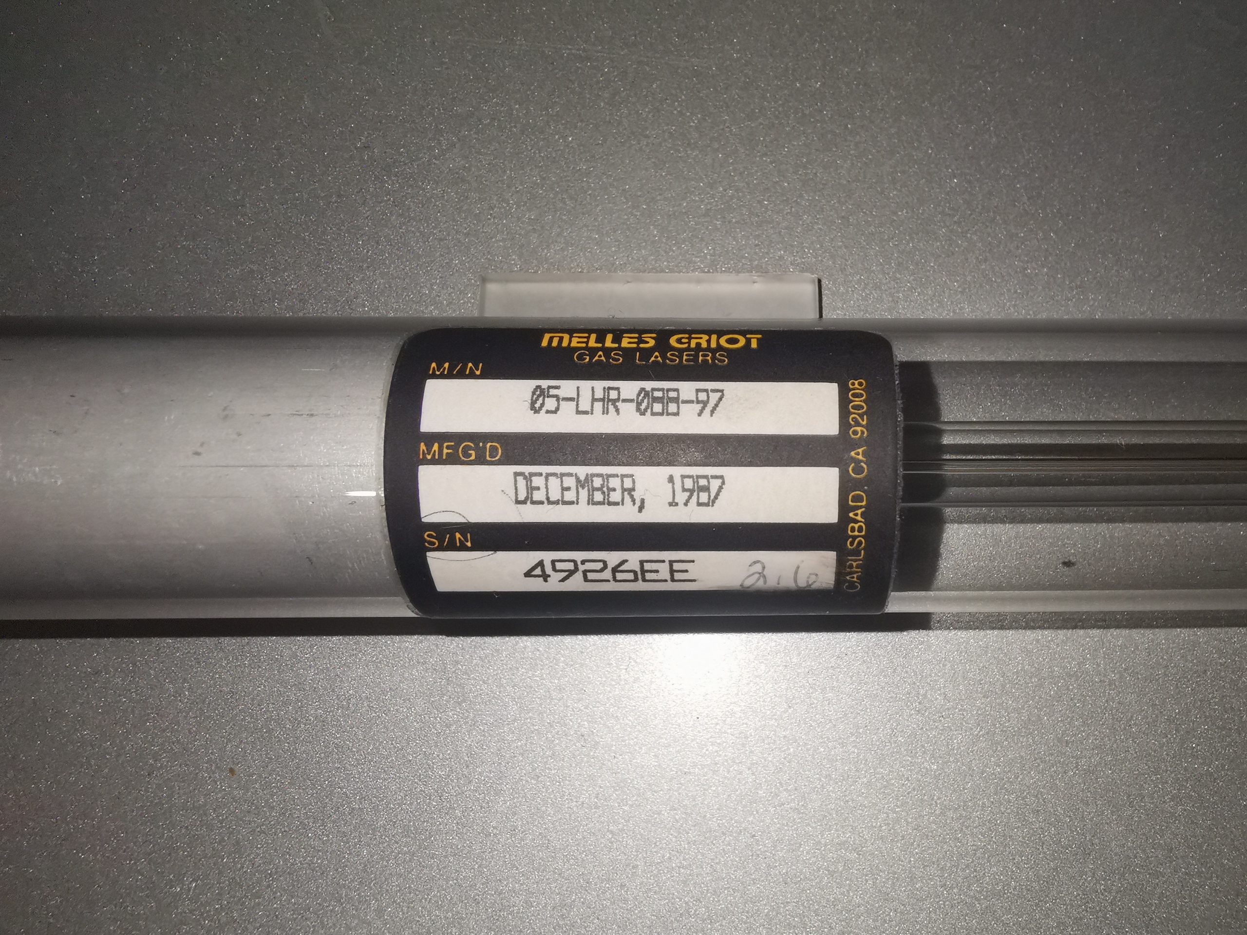
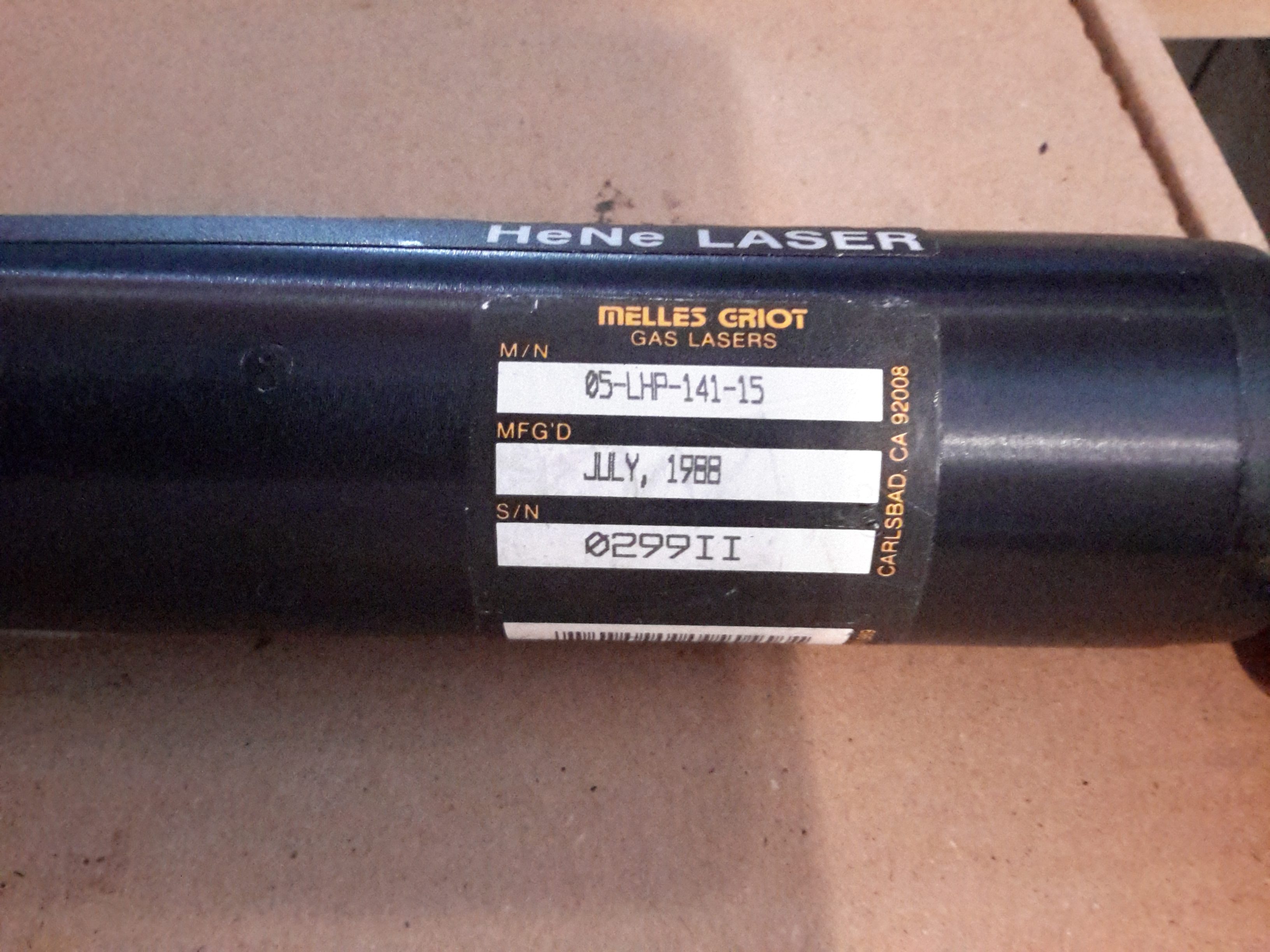
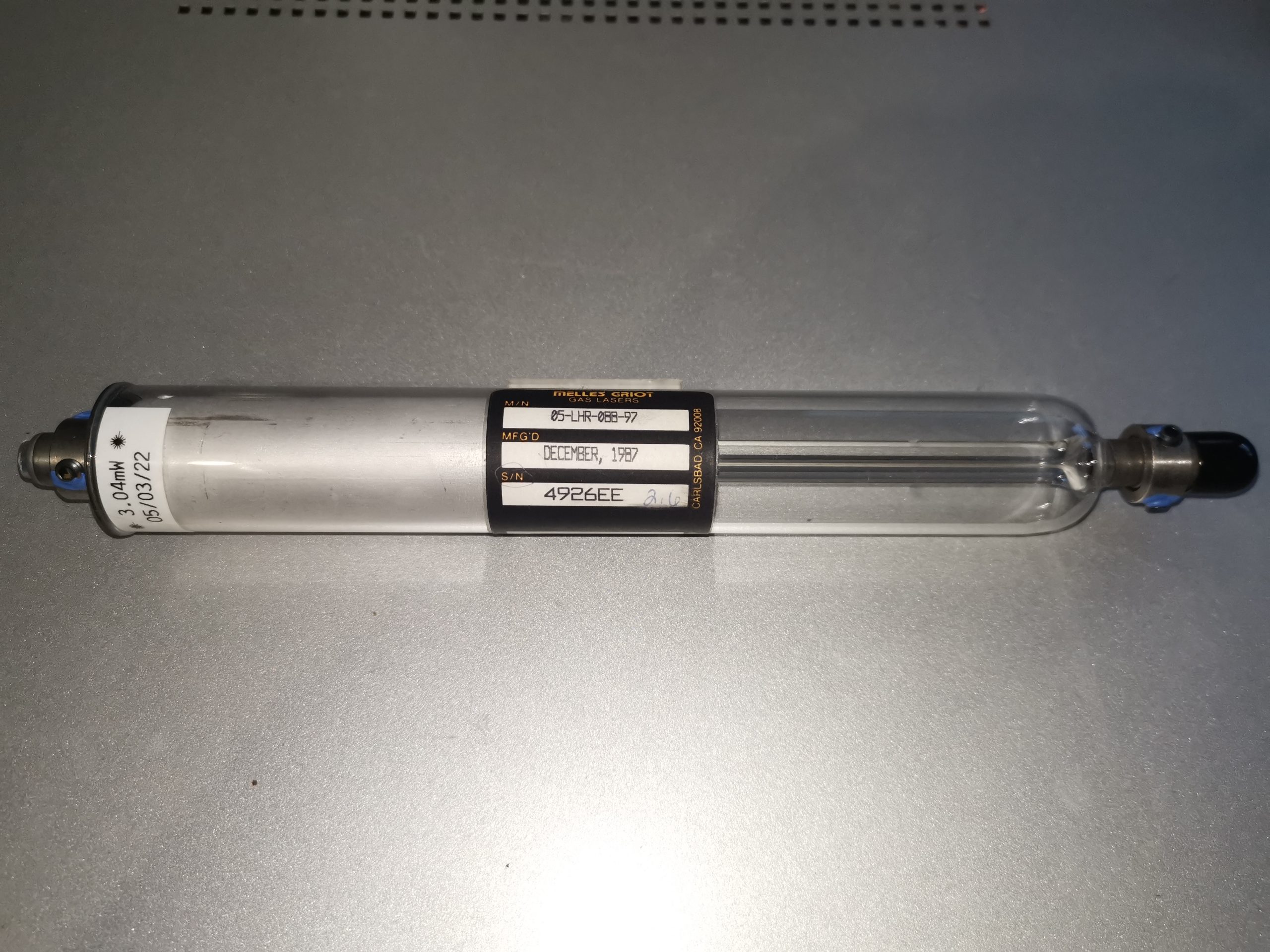
The label shows that this tube was manufactured back in 1987. 34 years at the time of writing! There is a slight amount of brown deposit in the main bore, indicating the tube has seen some use, however it’s nowhere near as bad as the Barcode scanner tube I have, which must have spent many years operating. I am assuming the “2.6” hand-written onto the label next to the serial number was the power measured at the factory.

Anode End
Anode End

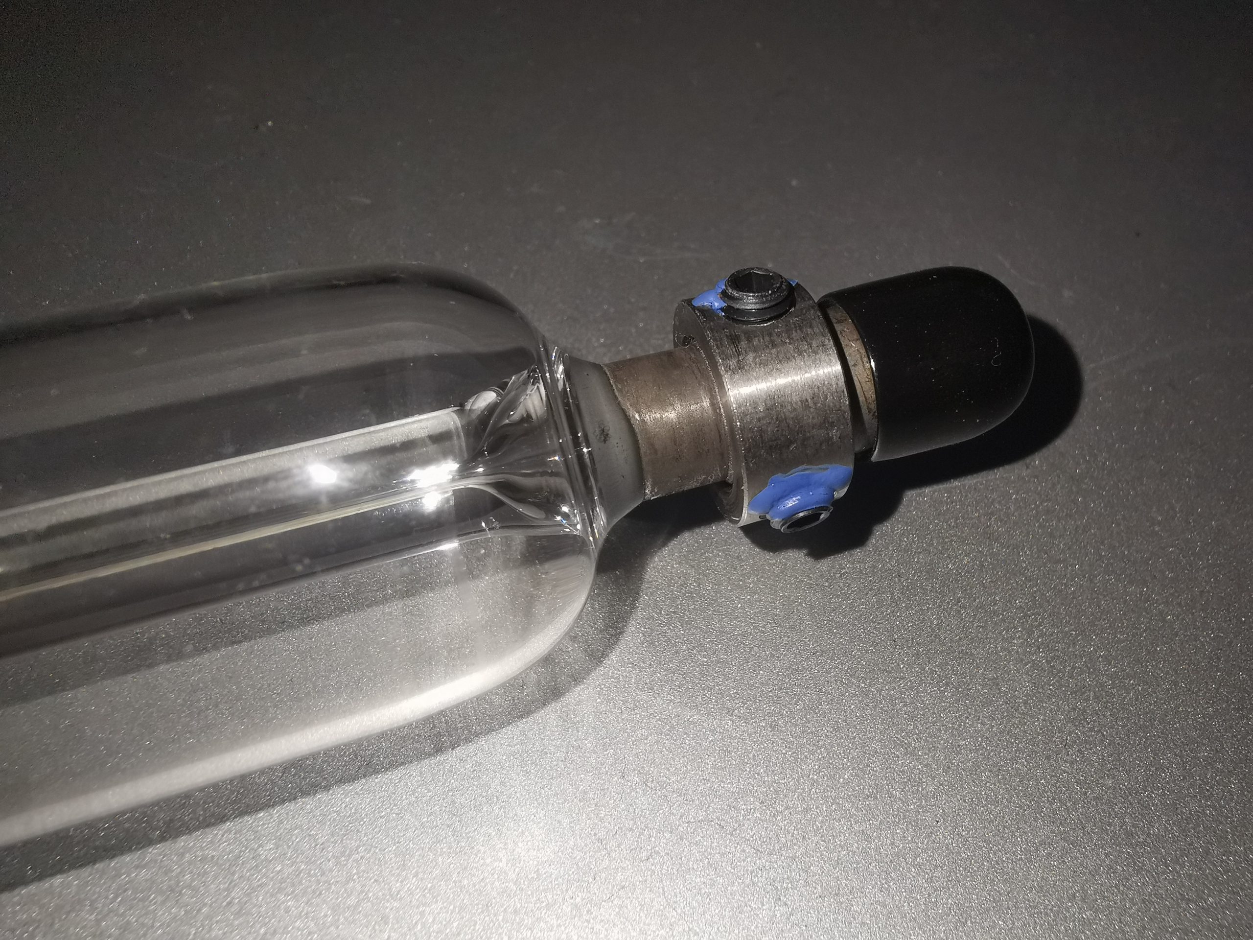
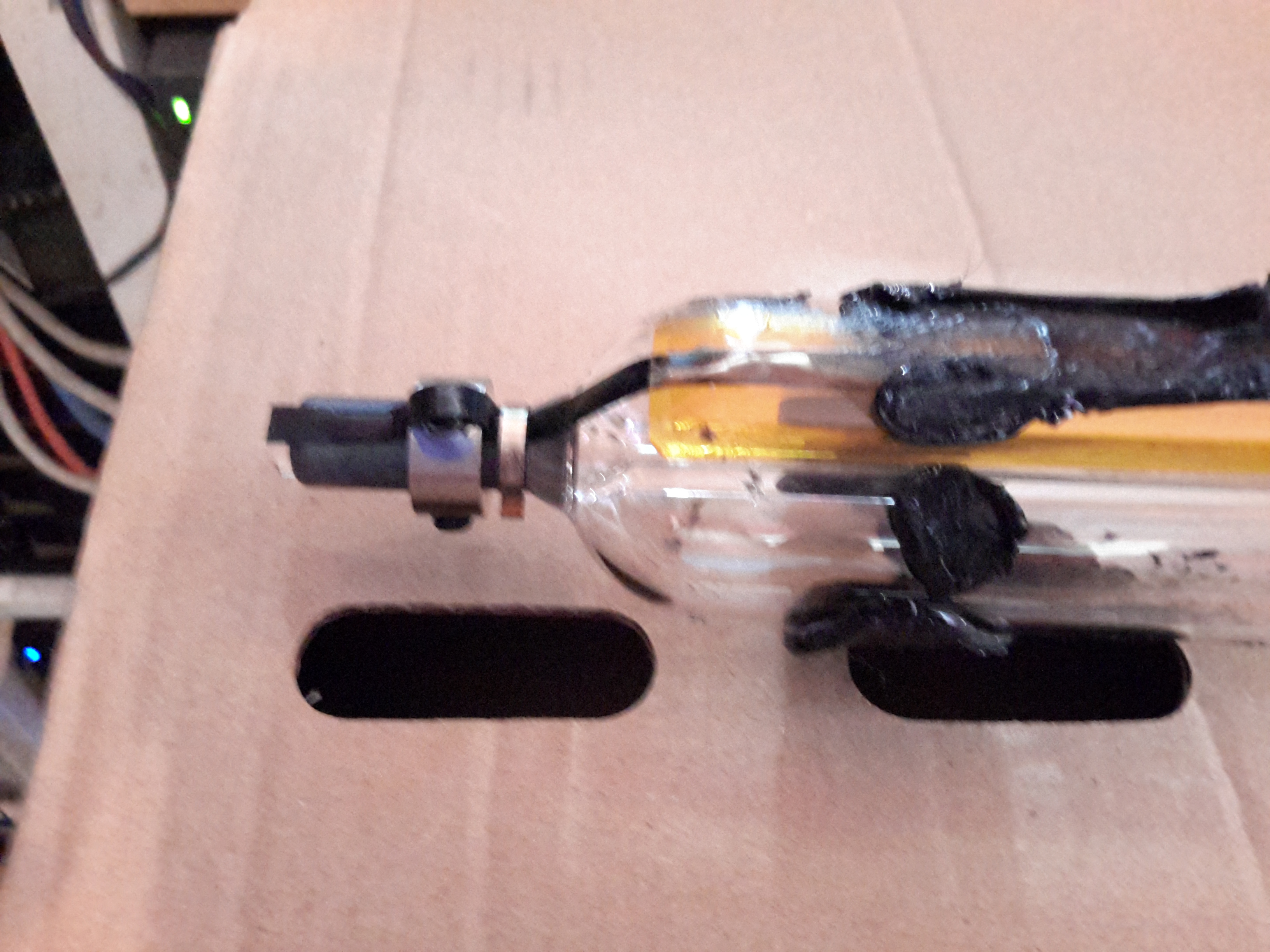
This tube is old enough to have 3-screw locking/adjustment collars on the mirror mounts. This one is at the anode end of the tube, with a cap over the HR mirror for protection.

OC Mirror
OC Mirror

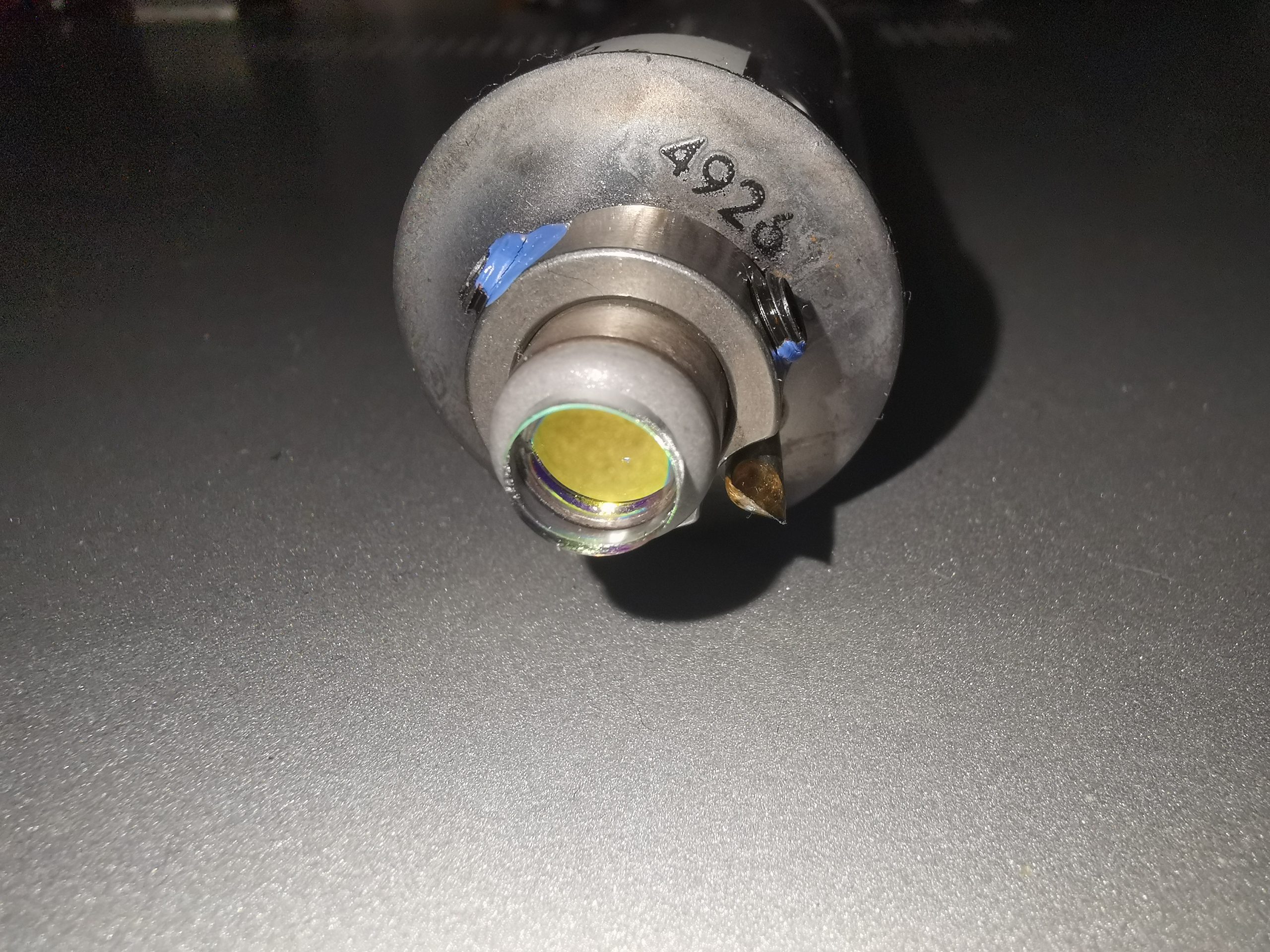
The OC (Cathode) end of the tube has the same locking collar.

Tube Mounts
Tube Mounts

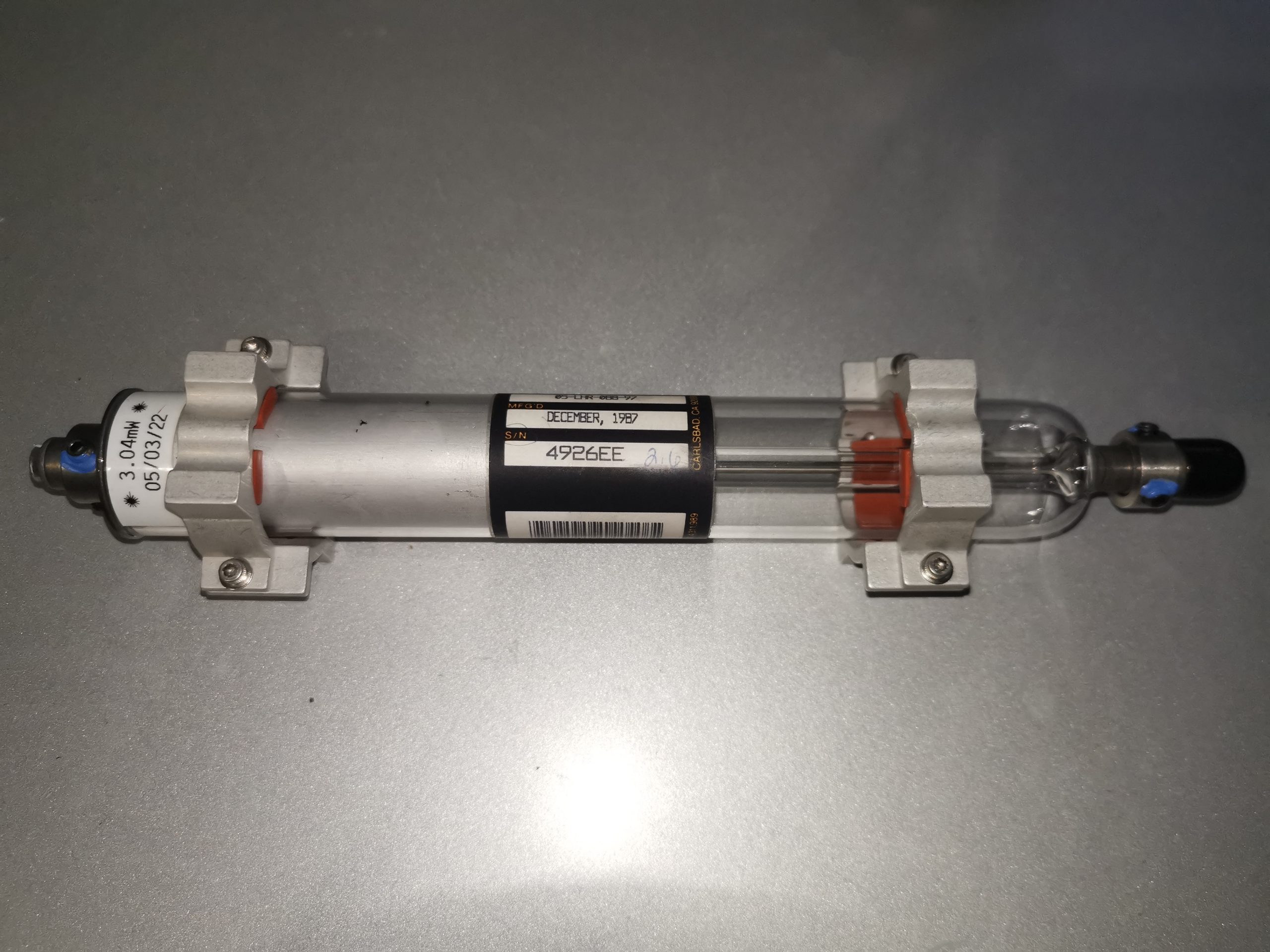
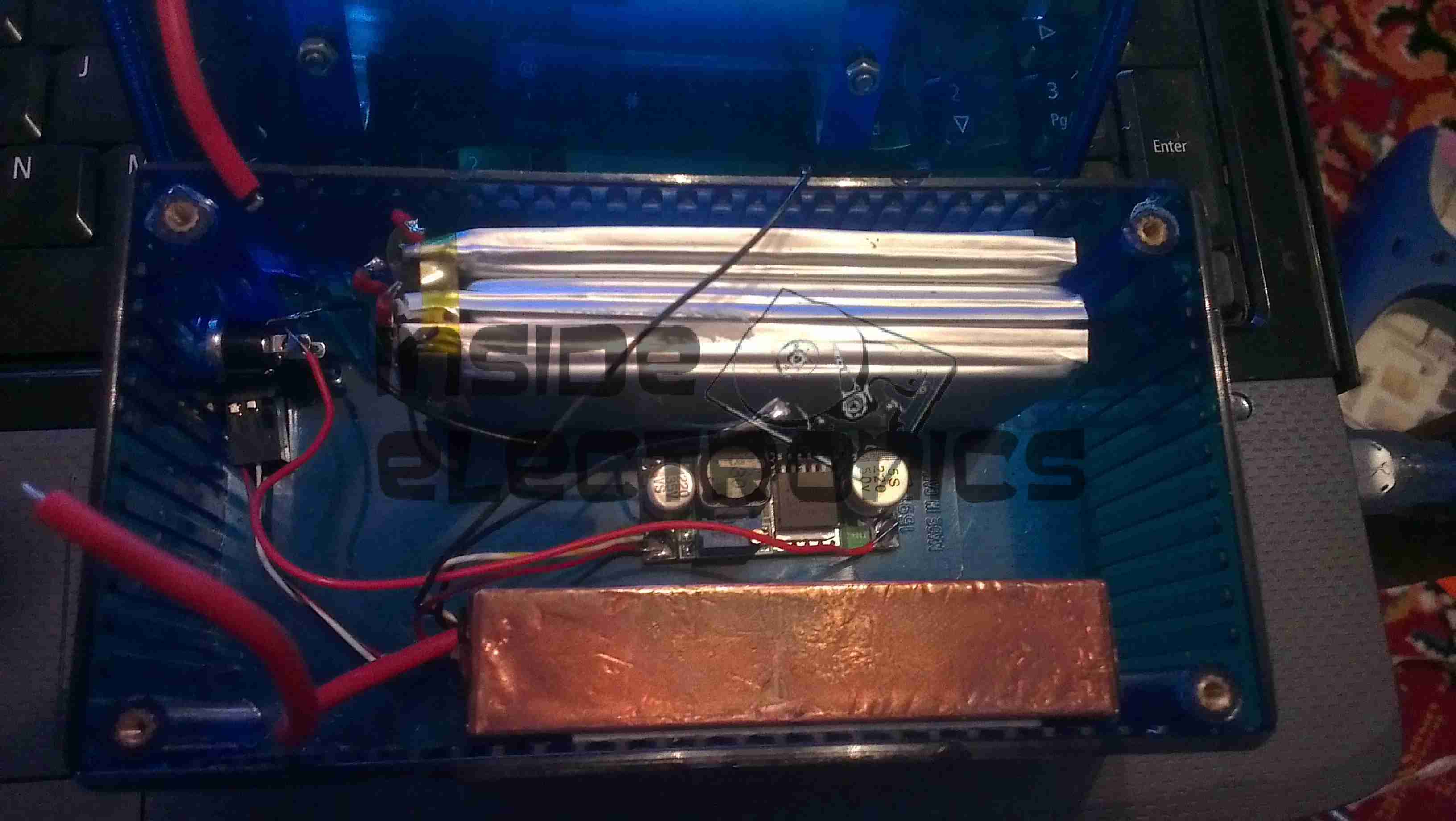
The original tube mounts are reattached here, made from Aluminium with silicone rubber pads.

Tube Running
Tube Running

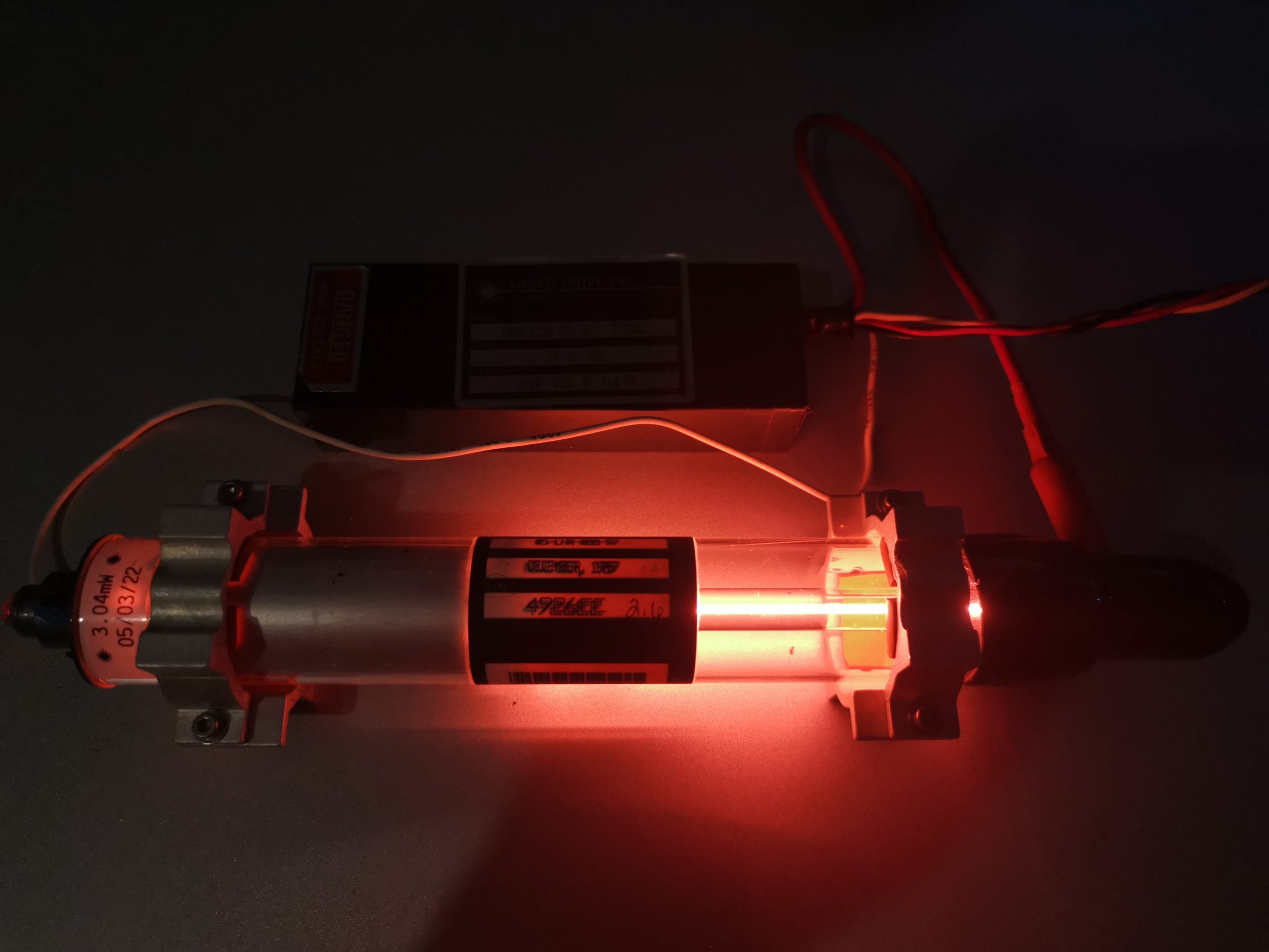
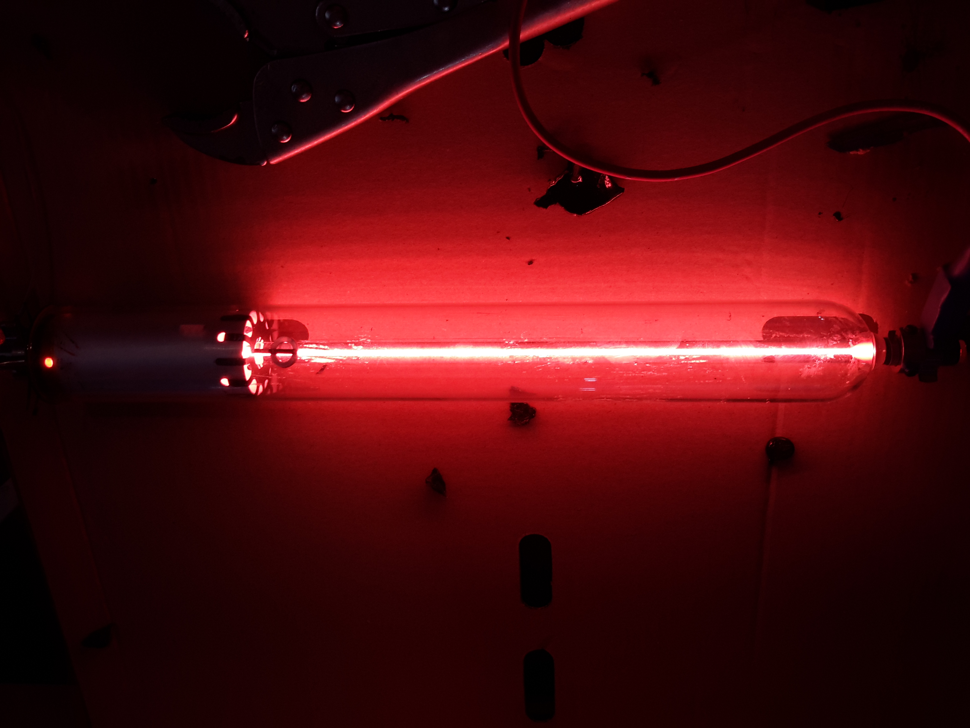
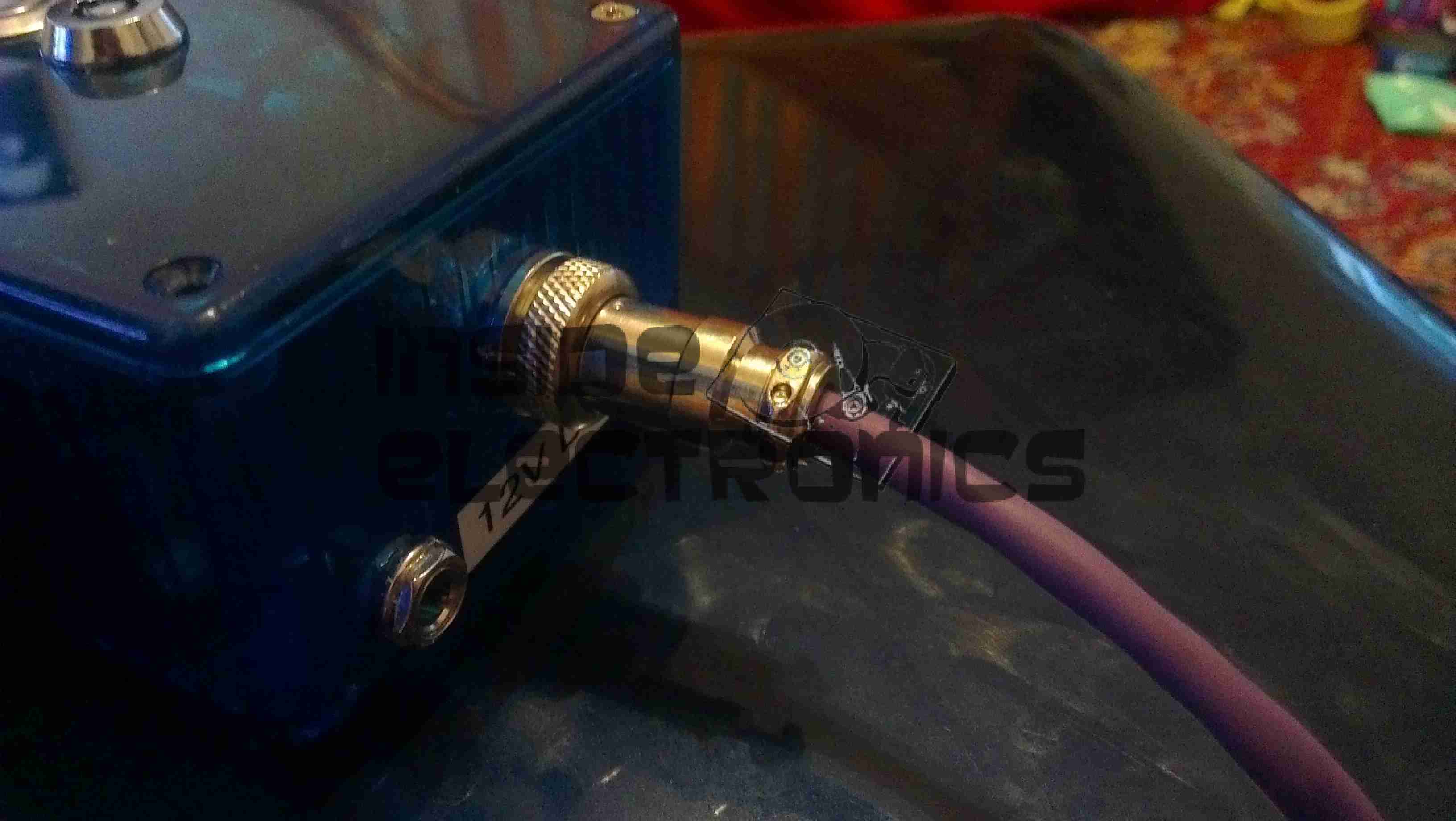
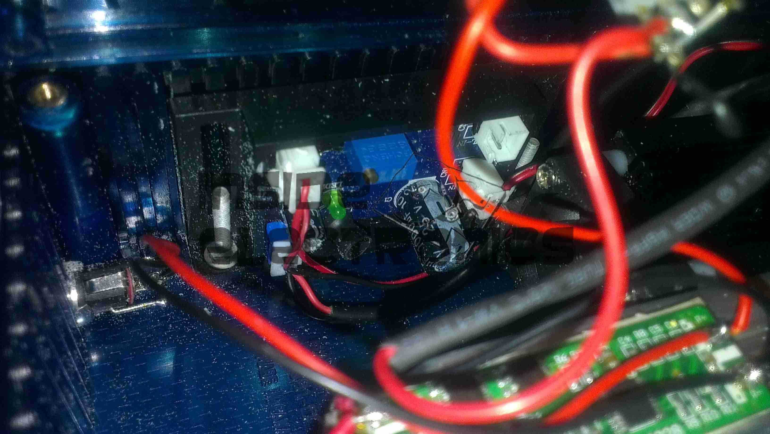
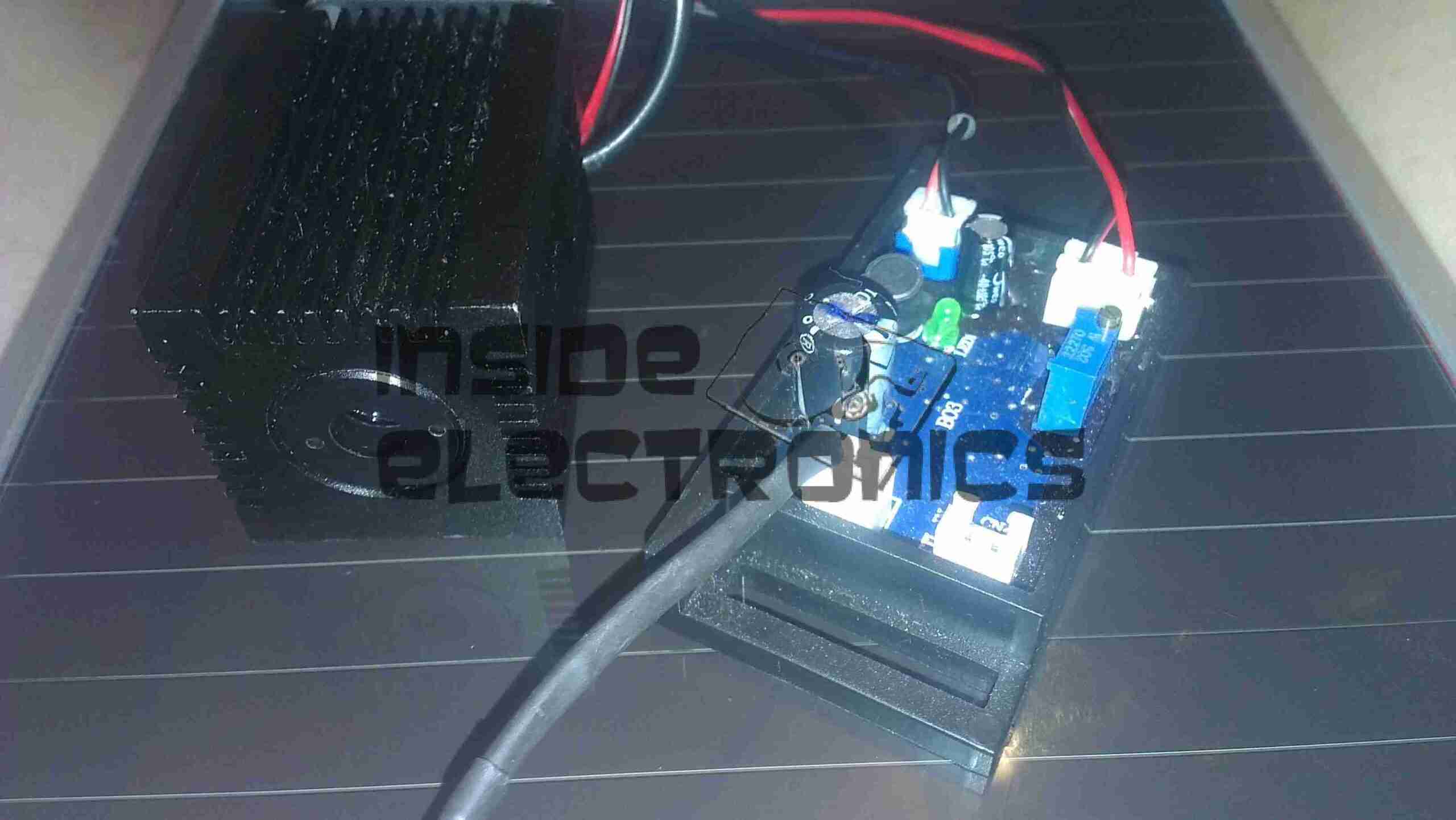
Here’s the tube running on a LaserDrive 4.5mA PSU. The camera doesn’t quite pick up the colour of the discharge, it’s more salmon-pink.

Bore Closeup
Bore Closeup

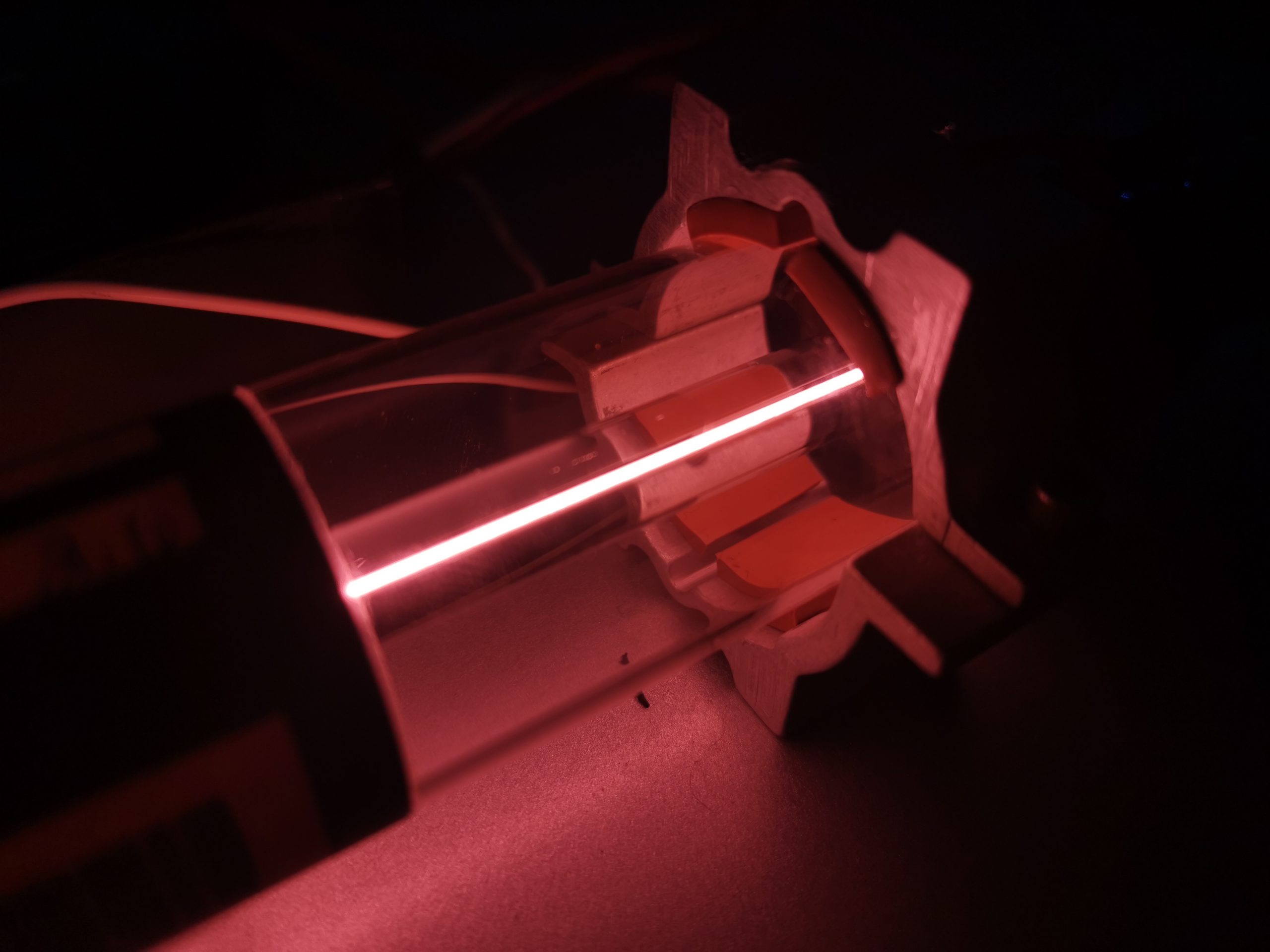
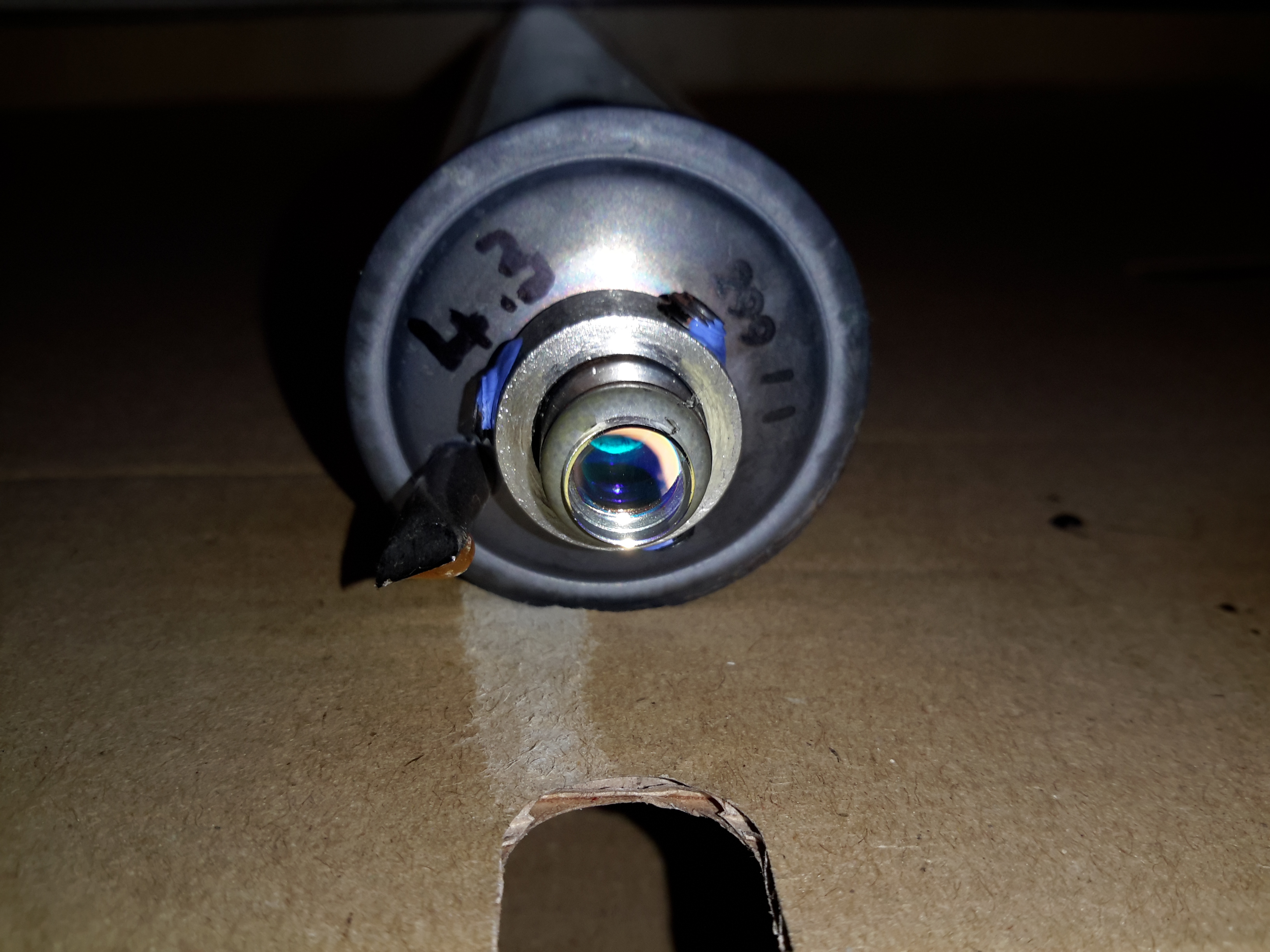
A closeup of the bore more accurately shows the colour of the glow discharge in the tube.

Beam

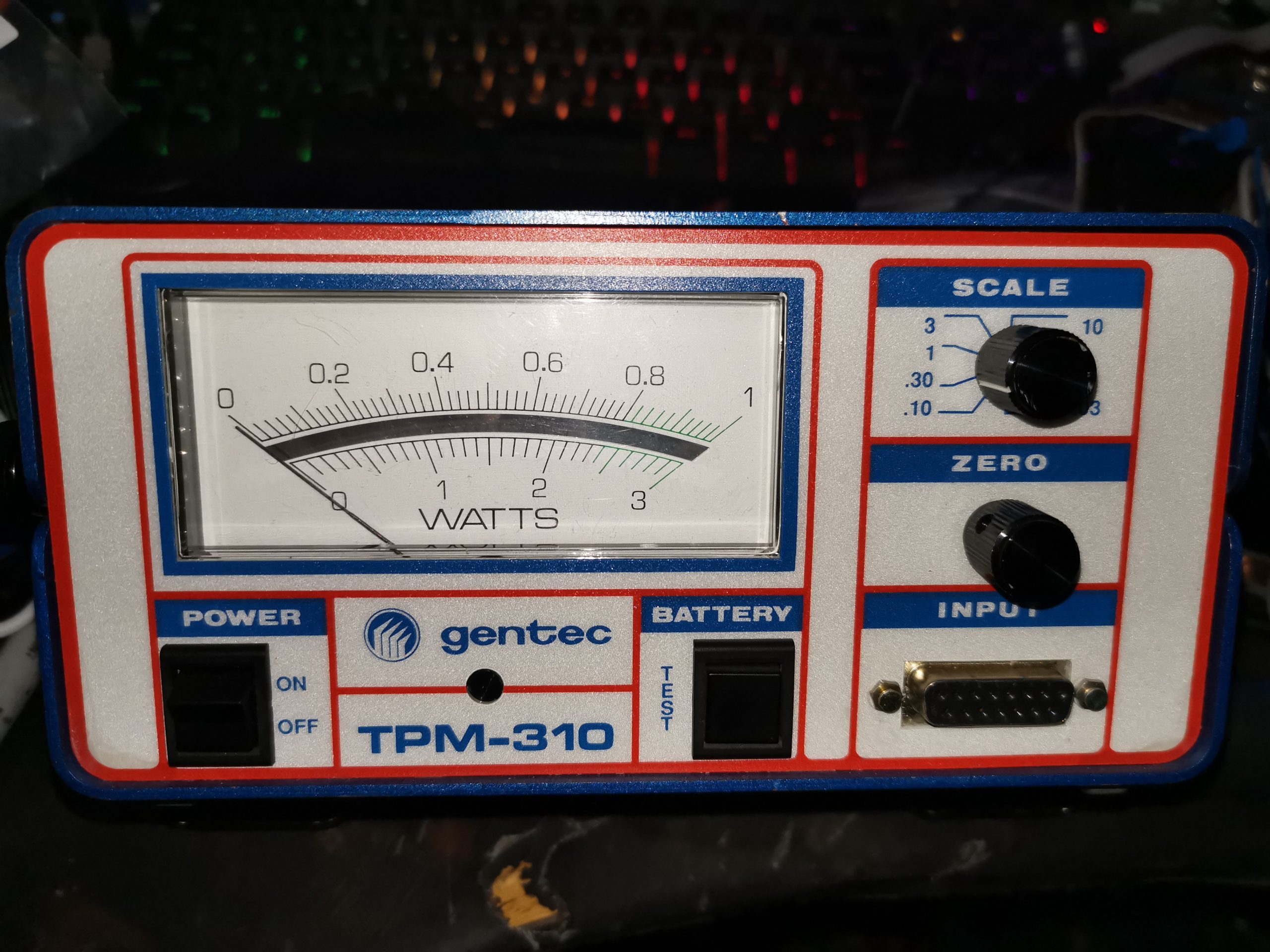
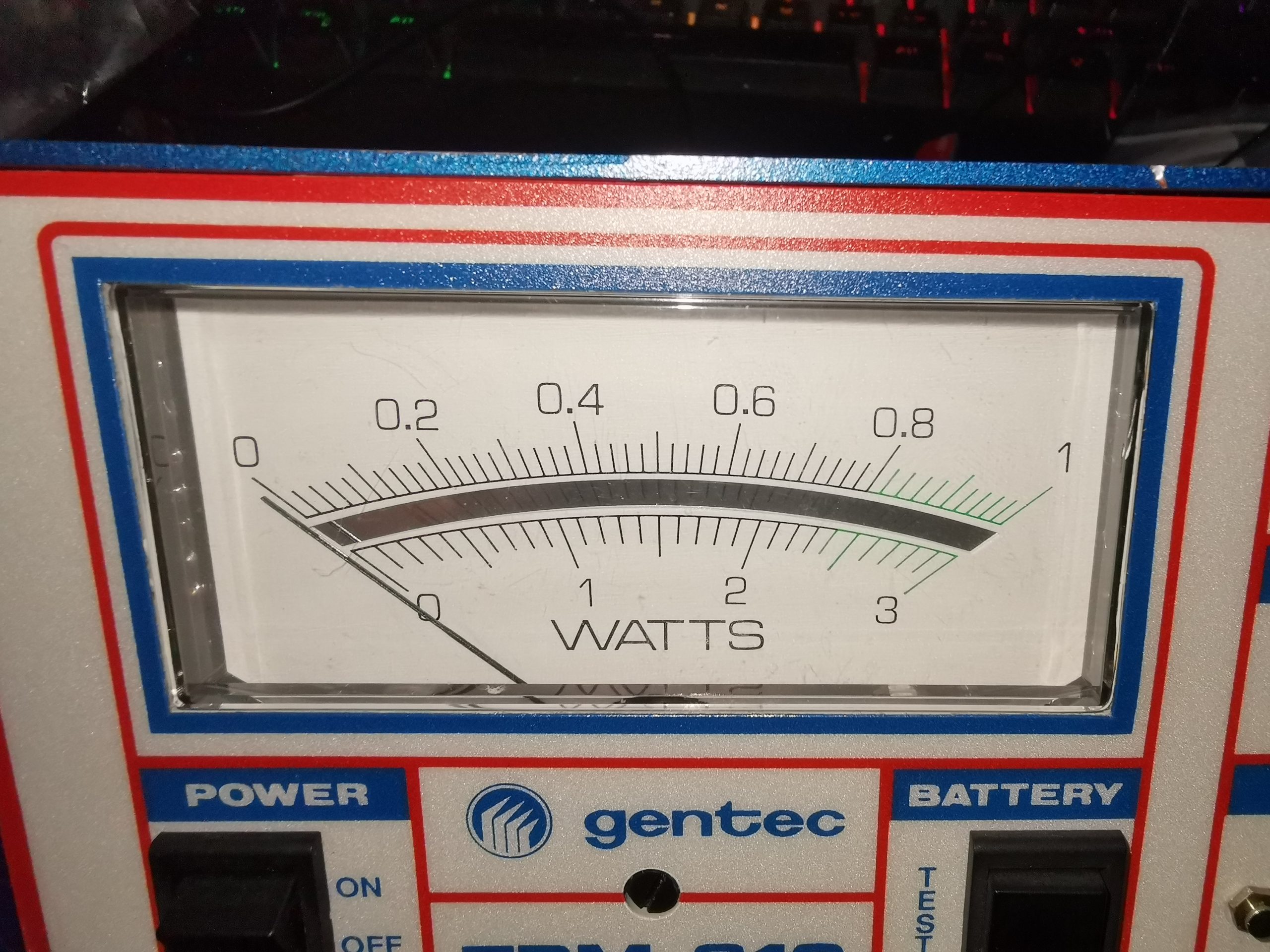
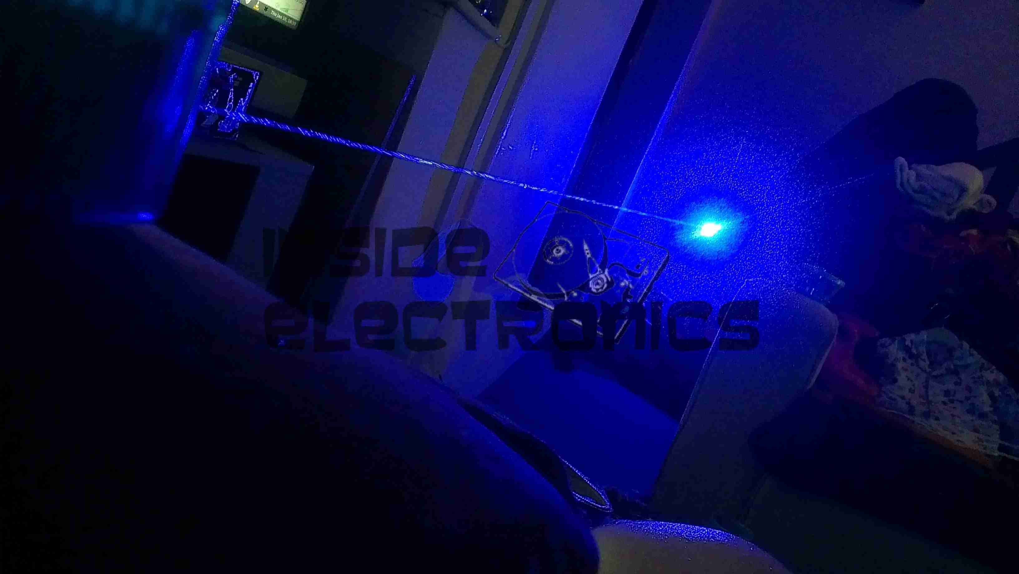
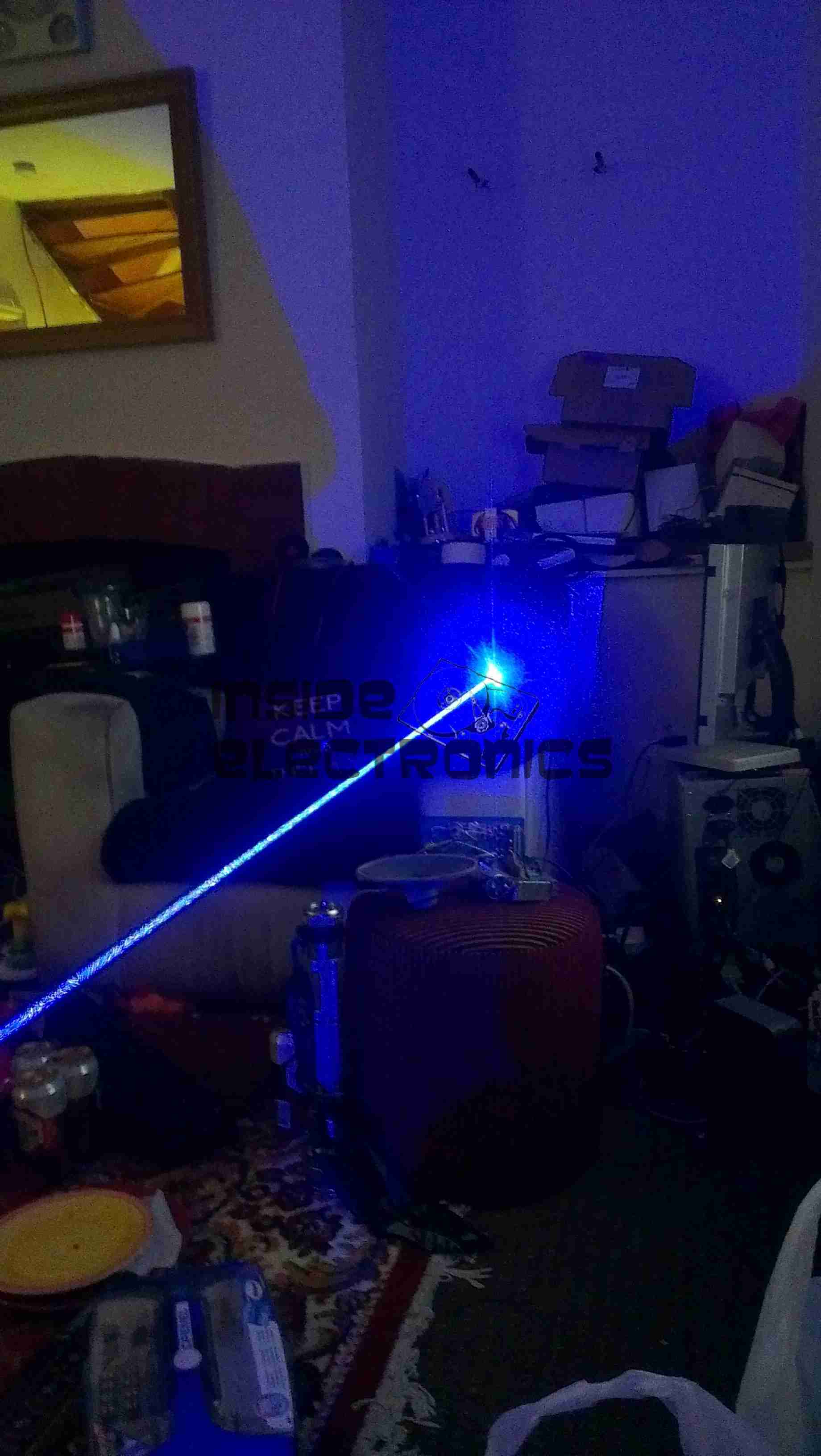
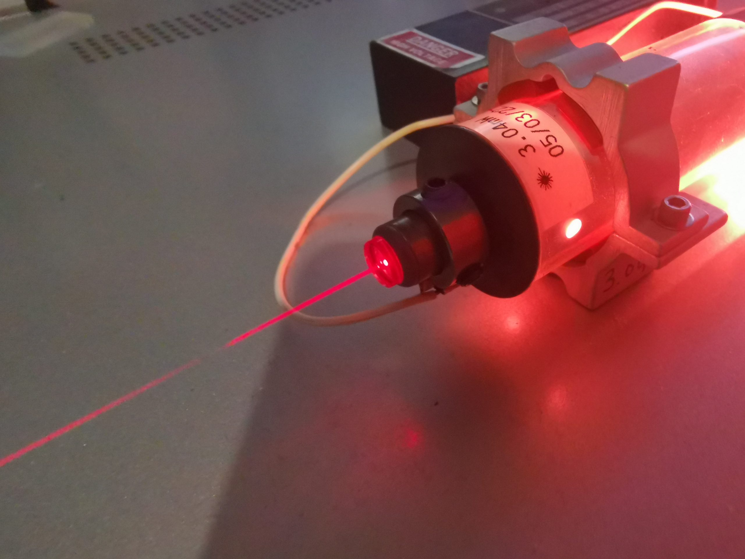
Finally, the output beam from the tube. This one actually measured at 3.04mW on a Coherent LaserCheck, a bit higher than the assumed factory measurement of 2.6mW!

Posted on 3 Comments

DIY Thermal Laser Power Sensor Build

TEC On Heatsink
TEC On Heatsink
TEC On Heatsink

I’ve been looking for ways to build a DIY Laser Power meter for some time now, but I had no way to calibrate anything. I have been aware of DIY thermopile sensors with TECs – but no way to verify any results until now. Since I have my Gentec meter to calibrate against, I can finally get on with the project.
In the photo above, is the Peltier/TEC module mounted to the heatsink with thermal compound. In this case it’s a TEC1-12706, pulled from a cheapo dehumidifier. The cold face (with the part number printing) is against the heatsink, and the hot face will serve as the beam target. This was cleaned with solvent, and roughed up a bit with silicon carbide abrasive paper – the abrasive needs to be harder than the Alumina ceramic the module is constructed from.

Optical Coating
Optical Coating

To be any good as an optical power sensor, the front face of the module needs to be coated with something to absorb as much energy from the laser beam as possible. In this case, black paint was used, as it’s completely matte when dried. Lampblack also works, and this can be coated onto a sensor face with just a wax candle, but this is far too fragile to be any practical use (being just carbon, it’s much more resistant to thermal damage from the laser beams though!).

Coated Sensor
Coated Sensor

After two coats of the paint are applied to the front face of the module, the sensor head is complete. Try to get this as smooth as possible for best results. I designed & 3D printed a retention bracket for the module, and matches up with the screws that hold the fan on the finned side. This also has a block on the bottom which I threaded 1/4-20 to fit a standard tripod thread.

Like all commercial laser power sensors, the beam should be expanded as much as possible to fill the full face of the sensor. A focused high-power beam will quickly destroy the coating!

After completion, the sensor needs to be characterised. For this I set a diode module to be as close to 1W as possible, according to my calibrated meter, and applied the beam to the constructed sensor. A load impedance of 68Ω was placed across the output leads as a load. For this unit, I obtained a reading of 83.5mV/W of applied power. Even for low power levels, the fan does need to be running on the back of the heatsink, as the cold side of the sensor heating up will skew the reading.

After calibration at 1W optical power, I then ran some more tests at higher powers – 2W gave exactly double the output voltage, and throughout the power range I am able to test, the sensor seems to be entirely linear in operation.

Posted on 1 Comment

Gentec TPM-310 Optical Power Meter Teardown

Front Panel
Front Panel
Front Panel

Here we have an optical power meter, vintage 1991! This is a Gentec unit, with scaling to to handle up to 10W with a suitable powerhead. Powered either with 4 PP3 9v batteries, or from a 24v DC jack on the rear, this unit is quite versatile. I managed to get this for very little money on eBay – similar units cost over £1,500 new – without a powerhead.

Meter Movement
Meter Movement

The unit is completely analogue, with no digital circuitry at all. The meter movement has a mirror on the scale for parallax correction. Under the movement are the main power switch & battery test switch, which uses the meter itself to show battery level.

User Controls
User Controls

The right hand side of the unit has the Zero adjustment, the range switch, and the DB15 powerhead input connector.

Board Left
Board Left

Taking the unit apart, with just 4 allen screws on the case reveals the mainboard. There’s very little back here! The active components are just Op-Amps – An OP07 ultralow offset in the bottom left corner is most likely the front-end amplifier, along with a few LF442ACN precision JFET input devices in the same area. The other amplifiers are LT1001 precision devices, with a 10mA output current capability. Most of the passives in this area are also high-stability & high precision parts.

Board Right
Board Right

The other side of the board handles the meter movement, and the power input section. There is a small daughterboard with another LT1001 Op-Amp on board, along with some passives, and the battery inputs go into here, however I’m not exactly sure what this is doing – there is another connection to the rear panel 1v analogue output BNC jack, so it may be the driver for that section. The 24v input is a single DC rail, however the 4 PP3 battery holders are wired as parallel pairs of batteries back to back, so a split +9v/-9v supply is generated.

Main PCB
Main PCB

An overall view of the board shows the wiring back to the battery holder, 1v analogue output jack & DC input connector.

Posted on 2 Comments

Melles-Griot 05-LHP-141-15 Helium Neon Laser Head & Tube Extraction

Melles Griot
He-Ne Laser Head
He-Ne Laser Head

Looking through eBay recently I came across a great deal on some Helium-Neon laser heads from Melles Griot. While definitely not new, these gas lasers are extremely long-lasting & I figured the tubes inside would make a nice addition to my laser collection. Doing some searching on the model number, these heads are rated at an optical output of 4mW, but depending on how much milage is on the tubes, the output may be a bit higher.

Data Label
Data Label

I got a pair of the heads, this one was manufactured in July 1988, the other March 1989.

OC End / Classification Label

The OC end of the head has the laser classification label & the beam shutter. Once I’d tested the laser heads to make sure they survived the post intact, I set at extracting the plasma tubes from the aluminium housings.
The end caps are fibre-reinforced plastic & are secured with epoxy resin, so some heating & brute force released the caps from the housing, giving access to the laser tube itself.

Glue Holes
Glue Holes

The laser tube is secured in these heads by hot glue – this was squirted into the housing via two rows of holes around the ends. (Some are secured with RTV silicone, which is substantially more difficult to remove).

Copper Tube
Copper Tube

I’ve no photos of the actual extraction process as it’s difficult enough as is without at least 5 hands. A heat gun was used to warm up the housing until the glue melted enough to slide the tube out of the housing. Since everything was hot at this stage, a piece of copper tubing (above), was slipped over the OC mirror mount, so I could push the tube out of the housing while the glue was soft. This also protected the mirror from damage while the tube was being removed.

Extracted Tube
Extracted Tube

After a few minutes of gentle pushing while keeping the housing hot, the tube was released! It’s still pretty well covered in the remains of the hot glue, but this is easily removed once the tube cools down to room temperature with Isopropanol. The line of Kapton tape running down the tube to the cathode end is insulating a start tape electrode, which is supposed to make the laser strike faster on power-up. Instead of being metal though, the electrode appears to be a carbon-loaded plastic tape.

Start Tape & Adhesive

Here’s the HR end of the tube, which also serves as the high voltage anode electrode. The start tape is clipped onto the mirror mount, but all this will be removed.

OC End
OC End

The OC end of the laser, where the beam emerges. What I think is the mW rating of the tubes is written on the end cap, probably from when the tubes were manufactured.

Tube Energized
Tube Energized

Applying power from a He-Ne laser PSU confirmed the tube still works!

Posted on Leave a comment

445nm Laser TTL Interface

TTL Interface
TTL Interface

In preparation for my laser scanner project, I have modified my existing 445nm laser to accept a TTL blanking input. The laser driver is already enabled for this & just required an extra connection to interface with my laser scanner showboard. I have used an 8-pin connection to allow the same cable & interface to be used with an RGB laser system, when it arrives. The signals are as follows, from top centre, anti-clockwise:

Pin 1: +12v Power
Pin 2: Blue TTL
Pin3: GND
Pin 4: Green TTL
Pin 5: GND
Pin 6: Red TTL
Pin 7: GND
Centre: Power GND


Custom TTL Cable
Custom TTL Cable

Here is the custom 8 core cable, which connects to the laser scanner show board. This cable allows the laser to be used for projection while still retaining the portable function & the keylock arming switch. When plugged in the cable bypasses the keyswitch & provides 12v DC direct to the laser driver.

Posted on Leave a comment

He-Ne Laser

He-Ne Laser Mount
He-Ne Laser Mount

Having had a He-Ne laser tube for a while & the required power supply, it was time to mount the tube in a more sturdy manner. Above the tube is mounted with a pair of 32mm Terry Clips, with the power leads passing through the plastic top. The ballast resistor is built into the silicone rubber on the anode end of the tube. (Right).
Output power is about 1mW for this tube, which came from a supermarket barcode scanner from the 90’s. The tube is dated August 1993 & is manufactured by Aerotech.

Internals
Internals

Inside the box is the usual 2.2Ah 12v Li-Po battery pack & the brick type He-Ne laser supply. The small circuit in the centre is a switchmode converter that drops the 12v from the battery pack to the 5v required for the laser supply.