Posted on 3 Comments

DIY Thermal Laser Power Sensor Build

TEC On Heatsink
TEC On Heatsink
TEC On Heatsink

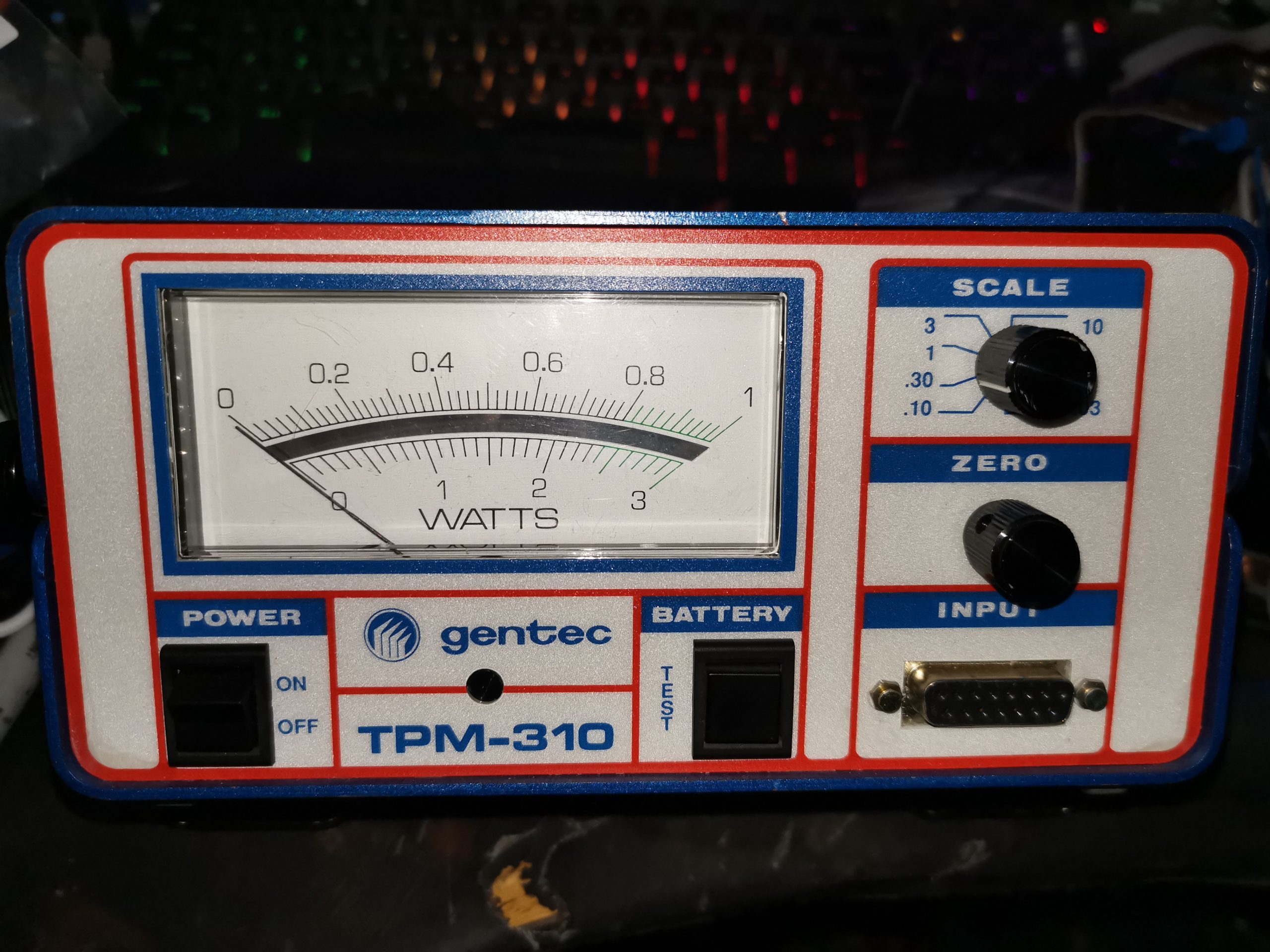
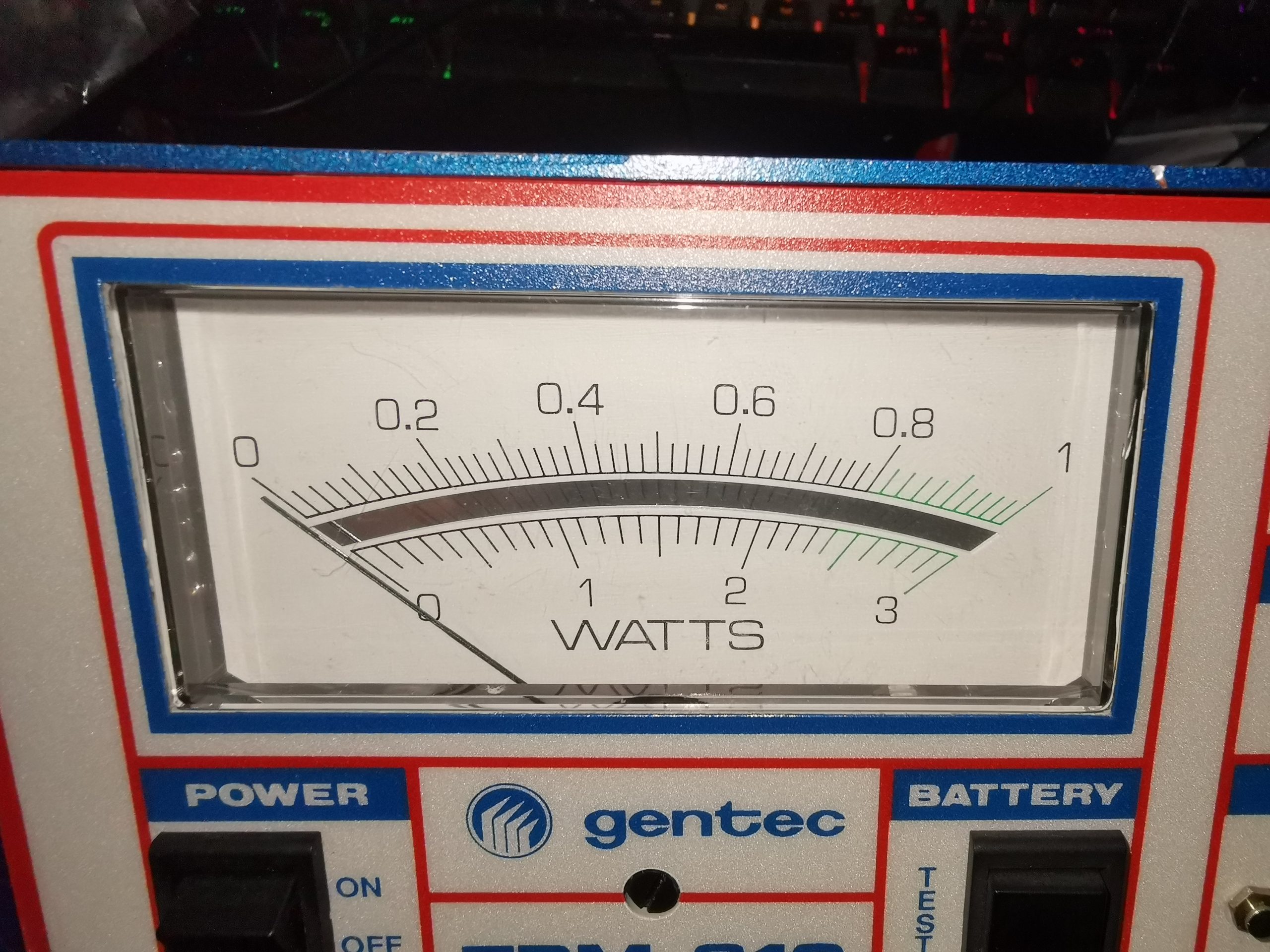
I’ve been looking for ways to build a DIY Laser Power meter for some time now, but I had no way to calibrate anything. I have been aware of DIY thermopile sensors with TECs – but no way to verify any results until now. Since I have my Gentec meter to calibrate against, I can finally get on with the project.
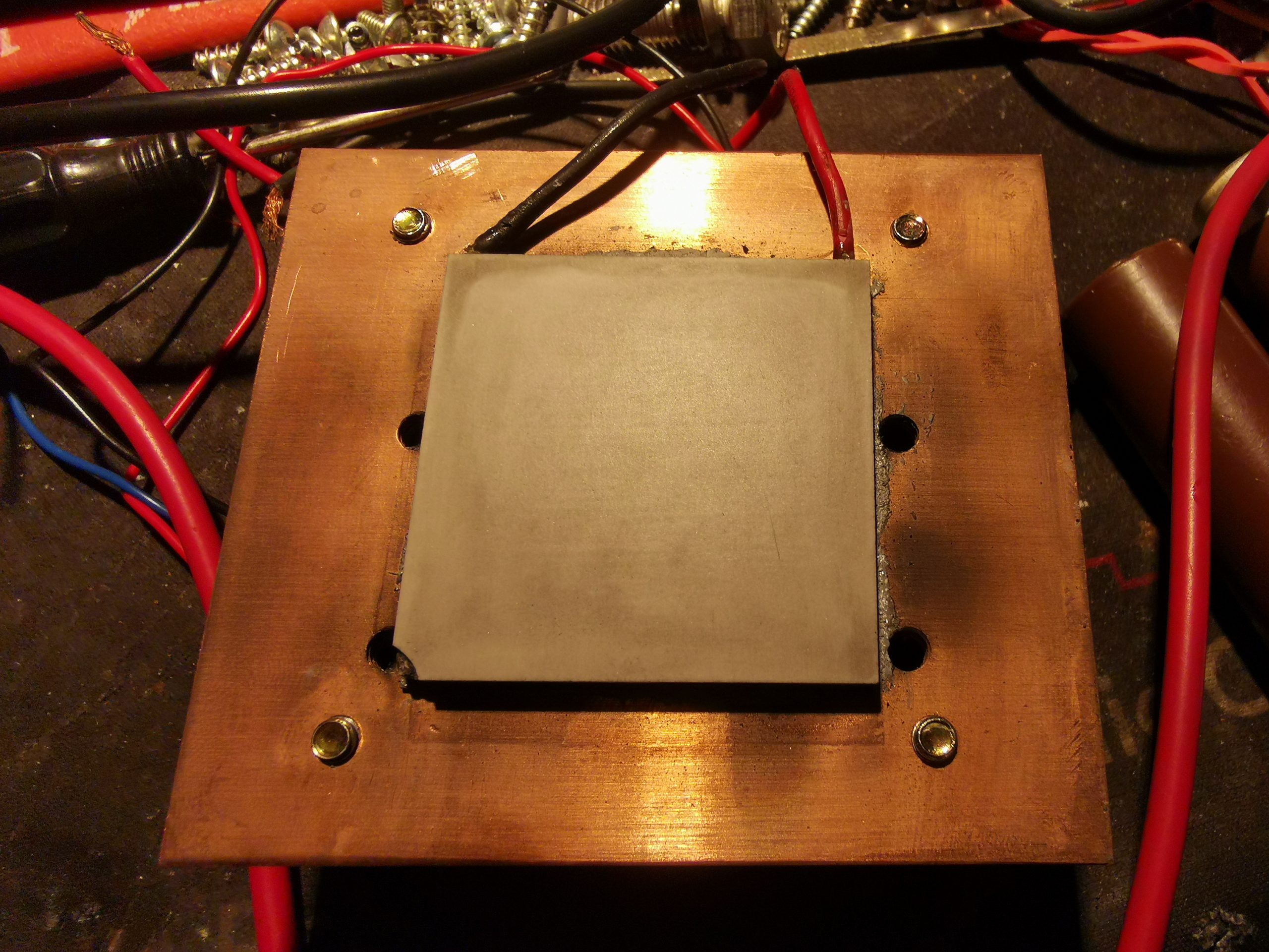
In the photo above, is the Peltier/TEC module mounted to the heatsink with thermal compound. In this case it’s a TEC1-12706, pulled from a cheapo dehumidifier. The cold face (with the part number printing) is against the heatsink, and the hot face will serve as the beam target. This was cleaned with solvent, and roughed up a bit with silicon carbide abrasive paper – the abrasive needs to be harder than the Alumina ceramic the module is constructed from.

Optical Coating
Optical Coating

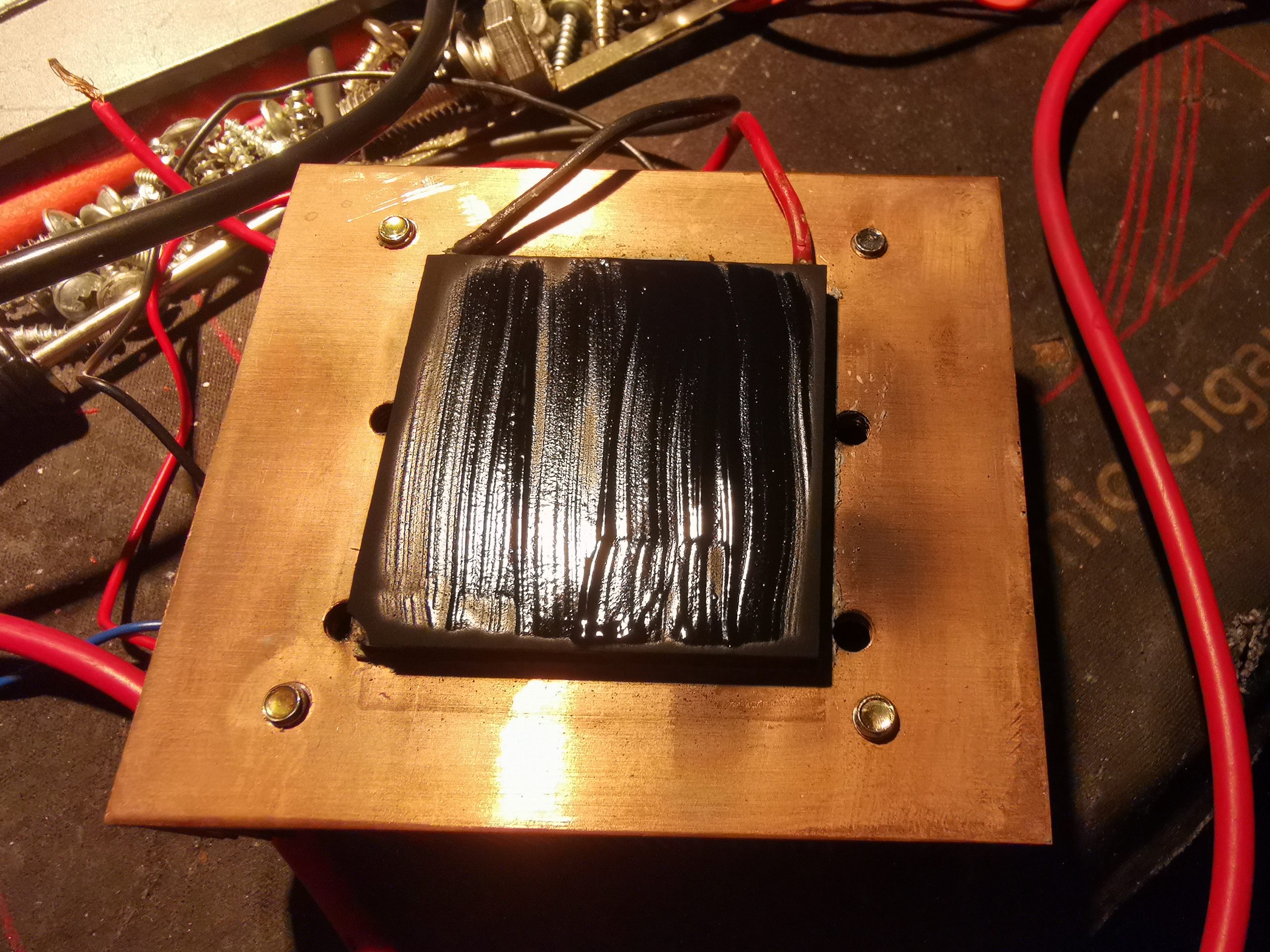
To be any good as an optical power sensor, the front face of the module needs to be coated with something to absorb as much energy from the laser beam as possible. In this case, black paint was used, as it’s completely matte when dried. Lampblack also works, and this can be coated onto a sensor face with just a wax candle, but this is far too fragile to be any practical use (being just carbon, it’s much more resistant to thermal damage from the laser beams though!).

Coated Sensor
Coated Sensor

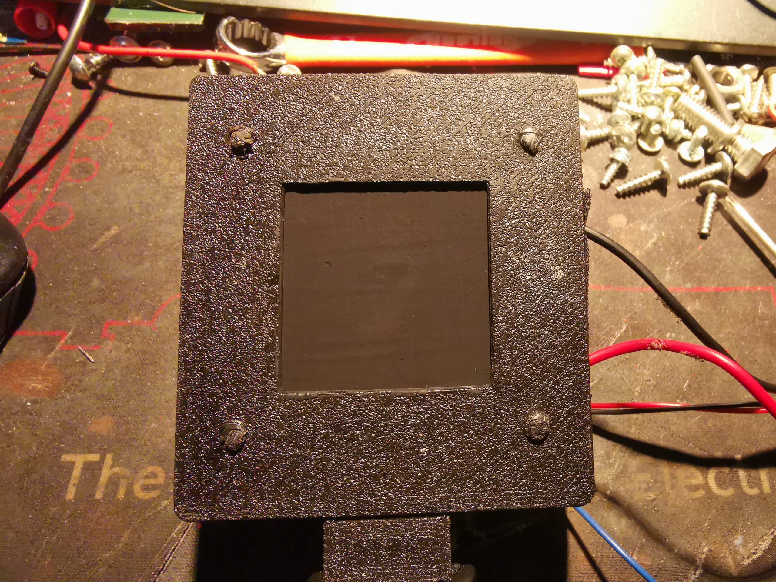
After two coats of the paint are applied to the front face of the module, the sensor head is complete. Try to get this as smooth as possible for best results. I designed & 3D printed a retention bracket for the module, and matches up with the screws that hold the fan on the finned side. This also has a block on the bottom which I threaded 1/4-20 to fit a standard tripod thread.

Like all commercial laser power sensors, the beam should be expanded as much as possible to fill the full face of the sensor. A focused high-power beam will quickly destroy the coating!

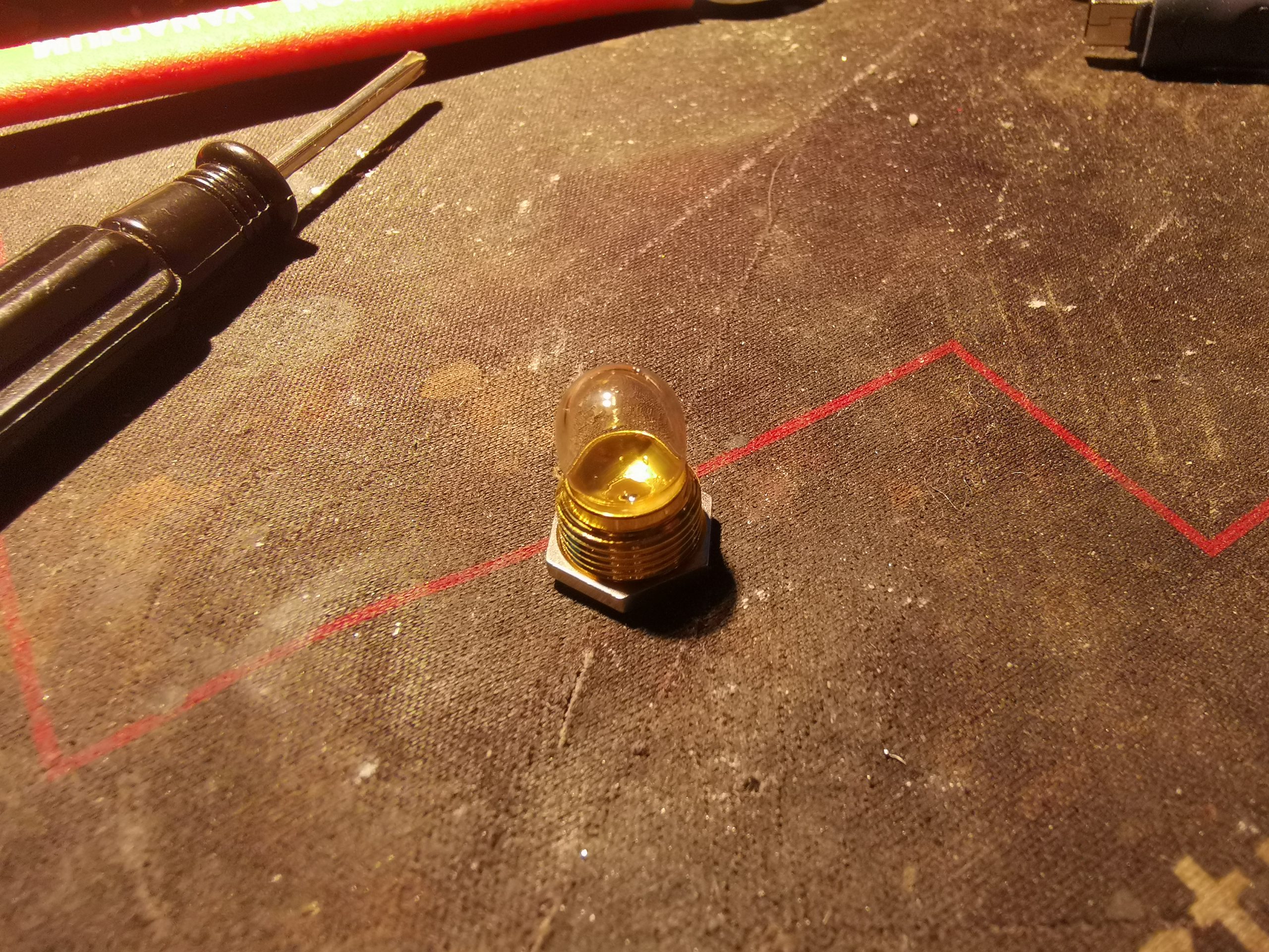
After completion, the sensor needs to be characterised. For this I set a diode module to be as close to 1W as possible, according to my calibrated meter, and applied the beam to the constructed sensor. A load impedance of 68Ω was placed across the output leads as a load. For this unit, I obtained a reading of 83.5mV/W of applied power. Even for low power levels, the fan does need to be running on the back of the heatsink, as the cold side of the sensor heating up will skew the reading.

After calibration at 1W optical power, I then ran some more tests at higher powers – 2W gave exactly double the output voltage, and throughout the power range I am able to test, the sensor seems to be entirely linear in operation.

Posted on Leave a comment

Efratom LPRO-101 Rubidium Frequency Reference Teardown

Rubidium Glow
Internal Overview
Internal Overview

Time for another Rubidium Standard Teardown! This one was supposed to happen a year ago, however I completely forgot about this unit. This is an Efratom / Datum LPRO-101 Rb standard, which does differ somewhat internally from the previous unit I tore down. Above is the unit with the Mu-Metal top cover unclipped. The PCB is very tightly packed with components, and this unit dates to approx 1999. The way all of these units operate is with a standard Quartz oscillator, and locking that to a Rubidium physics package to gain the stability of an atomic reference.

Servo Section
Servo Section

The bottom left corner of the board has the C-Field control & servo section, with the C-Field (Frequency Adjust) pot on the left, with the selectable tuning resistor. There’s a mountain of 74 series glue logic in this unit, and will be visible in every shot. The adjustment pot can be accessed through a tube in the top cover with an adjustment tool.

VCXO Section
VCXO Section

Bottom right is the 20MHz VCXO section, with the main crystal in the TO-3 can wrapped in a heatsink at the bottom right. Again there’s more space for selectable components here, with a blank spot for another ceramic cap – most likely to further tune the operating frequency. One of the main regulators is here as well, an LM7805 in the TO-220 package.

Synthesizer Section
Synthesizer Section

Here’s the RF synthesizer, used to indirectly generate the 6.8GHz hyperfine transistion frequency of Rubidium. The synth here frequency multiplies the 20MHz main clock to 60MHz, and feeds this through a coaxial cable into a Step Recovery Diode, mounted inside the microwave cavity with the Rb cell. This section also sweeps the frequency to be able to obtain physics lock when powered up.

Physics Package
Physics Package

This is the very important section of the oscillator – the Rubidium Physics package. This section is heated to high temperature – 100°C for the lamp (the small section on the left), and 70°C for the vapour cell & microwave cavity (the larger section on the right).

Rubidium Lamphouse
Rubidium Lamphouse

The Rb spectral source is hiding inside this small casting, with a barrel tuning capacitor on the side. In these units, the lamps are driven with RF, through a coil of wire wrapped around the glass bulb of the lamp itself. In my case, I managed to pick up a 156MHz signal in this area with a spectrum analyser, so I can only assume this is the drive frequency for the lamp. The main RF drive MOSFET, an MRF160 sits underneath the lamp housing. The driver is a Colpitts oscillator, and drives the lamp with about 4W of RF power. The lamp is heated with a MOSFET thermally bonded to the other side of the housing, which can’t be seen here.

Microwave Cavity
Microwave Cavity

The other end of the physics package has the Rubidium Vapour cell, photodetector & step recovery diode housed in a microwave cavity. The coax cable feeding the 60MHz signal from the synthesizer can be seen going through a passthrough in the brass plate. Inside is the SRD & photodetector. This section is heated by further thermally bonded MOSFETs on the sides of the cavity housing.

Rubidium Lamp Bulb
Rubidium Lamp Bulb

Loosening the locknut on the lamp housing, and gently unscrewing the gold-plated holder allows removal of the bulb. The tiny bead of Rubidium metal can be just seen in the pinch of the bulb, with a couple of spots on the outer part of the bulb. The lamp voltage on this unit was around 6.21v, however after removing the lamp & giving it a clean, and warming it to get the Rubidium to re-condense in the pinch got the voltage up to 7v – this is plenty healthy for one of these.
There’s definitely some wear though – there’s a slightly yellow tinge to the glass, and from what I have read in a couple of scientific papers on the subject of Rb Lamp Failure Modes, this is probably Rubidium Oxide, caused by an interaction between the metal & the glass.


rubidiumRubidium GlowA final photo shows the very pretty colour of these lamps – it’s a pastel purple colour, and surprisingly the camera picks this up very well.


Posted on 1 Comment

Gentec TPM-310 Optical Power Meter Teardown

Front Panel
Front Panel
Front Panel

Here we have an optical power meter, vintage 1991! This is a Gentec unit, with scaling to to handle up to 10W with a suitable powerhead. Powered either with 4 PP3 9v batteries, or from a 24v DC jack on the rear, this unit is quite versatile. I managed to get this for very little money on eBay – similar units cost over £1,500 new – without a powerhead.

Meter Movement
Meter Movement

The unit is completely analogue, with no digital circuitry at all. The meter movement has a mirror on the scale for parallax correction. Under the movement are the main power switch & battery test switch, which uses the meter itself to show battery level.

User Controls
User Controls

The right hand side of the unit has the Zero adjustment, the range switch, and the DB15 powerhead input connector.

Board Left
Board Left

Taking the unit apart, with just 4 allen screws on the case reveals the mainboard. There’s very little back here! The active components are just Op-Amps – An OP07 ultralow offset in the bottom left corner is most likely the front-end amplifier, along with a few LF442ACN precision JFET input devices in the same area. The other amplifiers are LT1001 precision devices, with a 10mA output current capability. Most of the passives in this area are also high-stability & high precision parts.

Board Right
Board Right

The other side of the board handles the meter movement, and the power input section. There is a small daughterboard with another LT1001 Op-Amp on board, along with some passives, and the battery inputs go into here, however I’m not exactly sure what this is doing – there is another connection to the rear panel 1v analogue output BNC jack, so it may be the driver for that section. The 24v input is a single DC rail, however the 4 PP3 battery holders are wired as parallel pairs of batteries back to back, so a split +9v/-9v supply is generated.

Main PCB
Main PCB

An overall view of the board shows the wiring back to the battery holder, 1v analogue output jack & DC input connector.