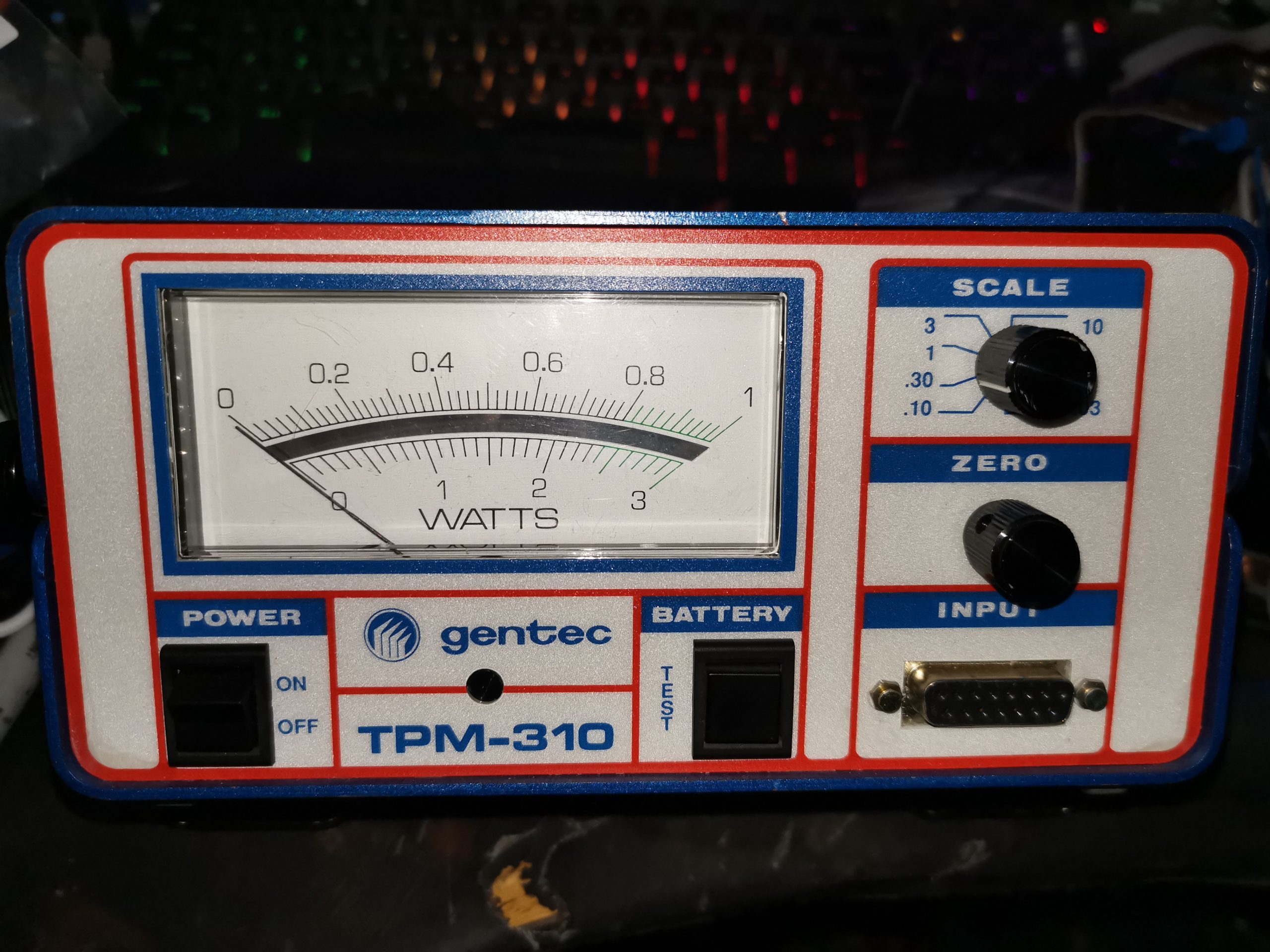
Here we have an optical power meter, vintage 1991! This is a Gentec unit, with scaling to to handle up to 10W with a suitable powerhead. Powered either with 4 PP3 9v batteries, or from a 24v DC jack on the rear, this unit is quite versatile. I managed to get this for very little money on eBay – similar units cost over £1,500 new – without a powerhead.
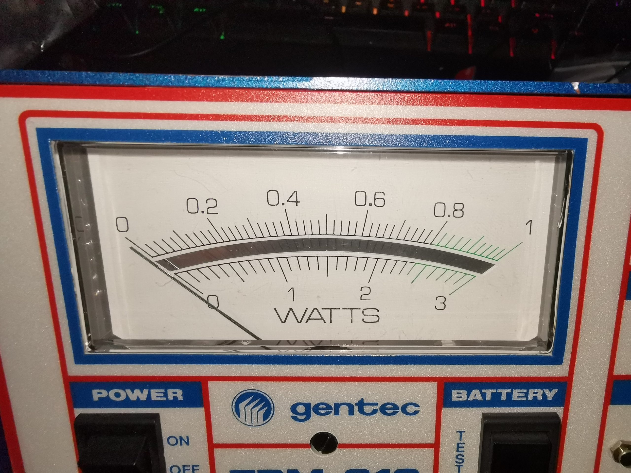
The unit is completely analogue, with no digital circuitry at all. The meter movement has a mirror on the scale for parallax correction. Under the movement are the main power switch & battery test switch, which uses the meter itself to show battery level.
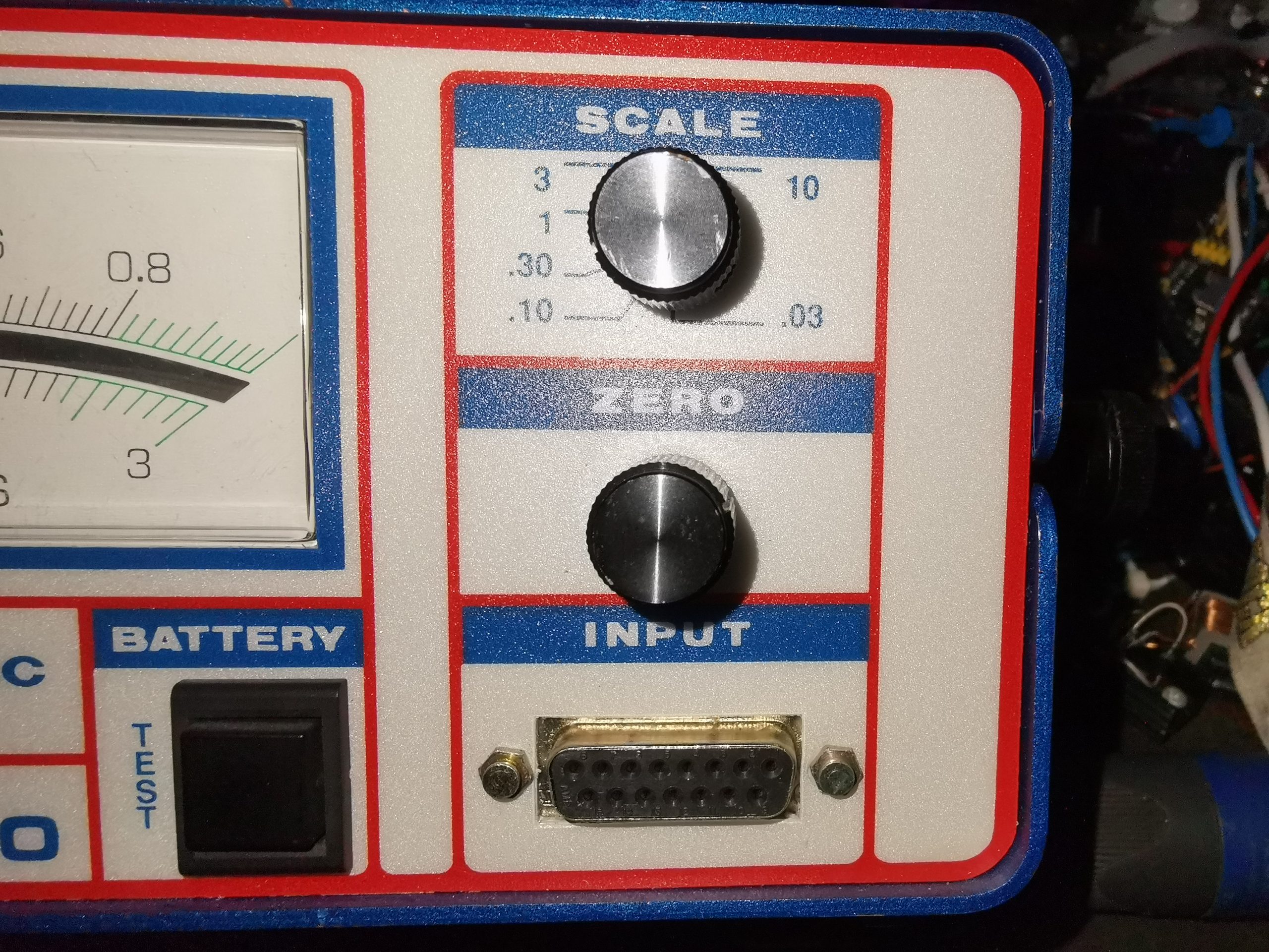
The right hand side of the unit has the Zero adjustment, the range switch, and the DB15 powerhead input connector.
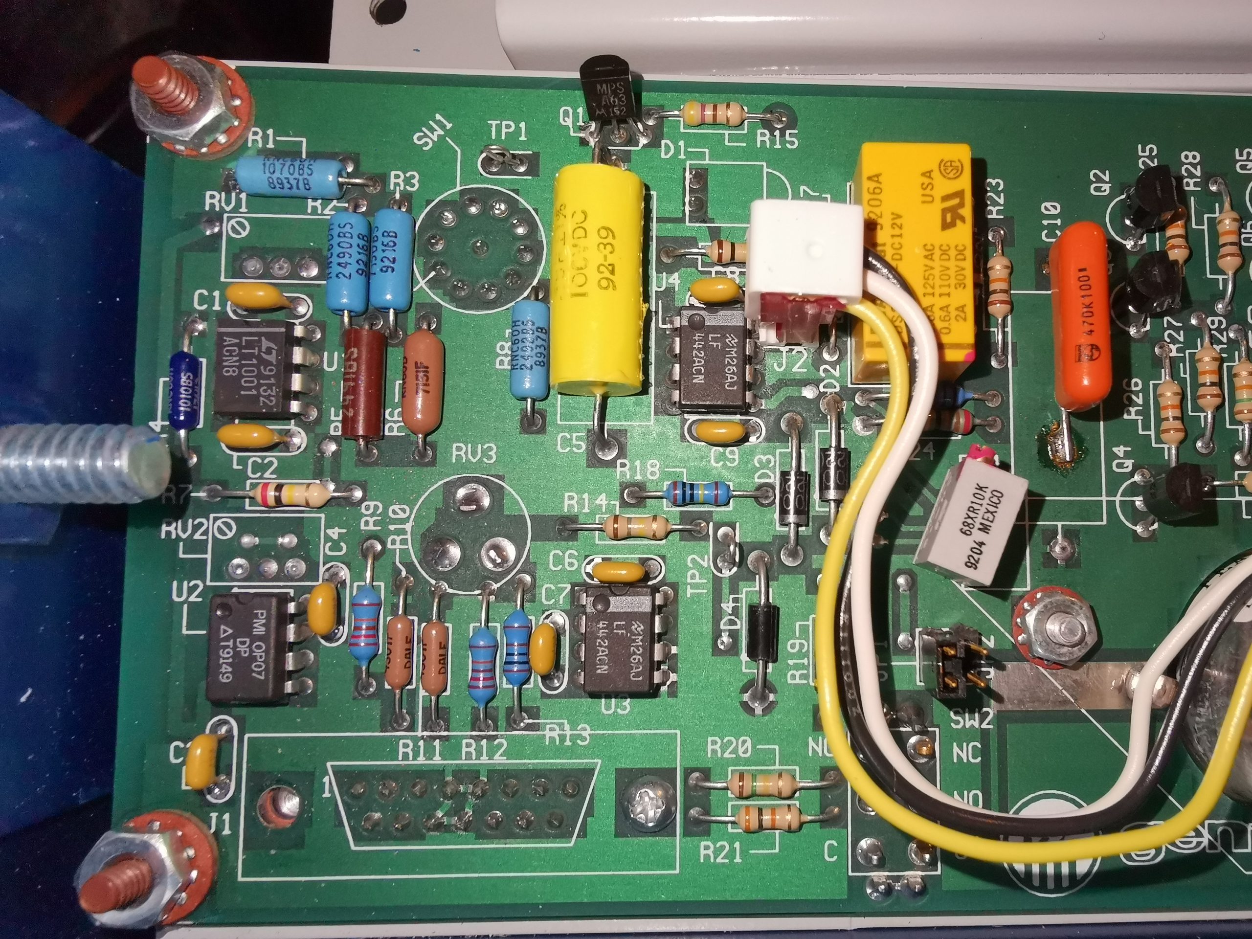
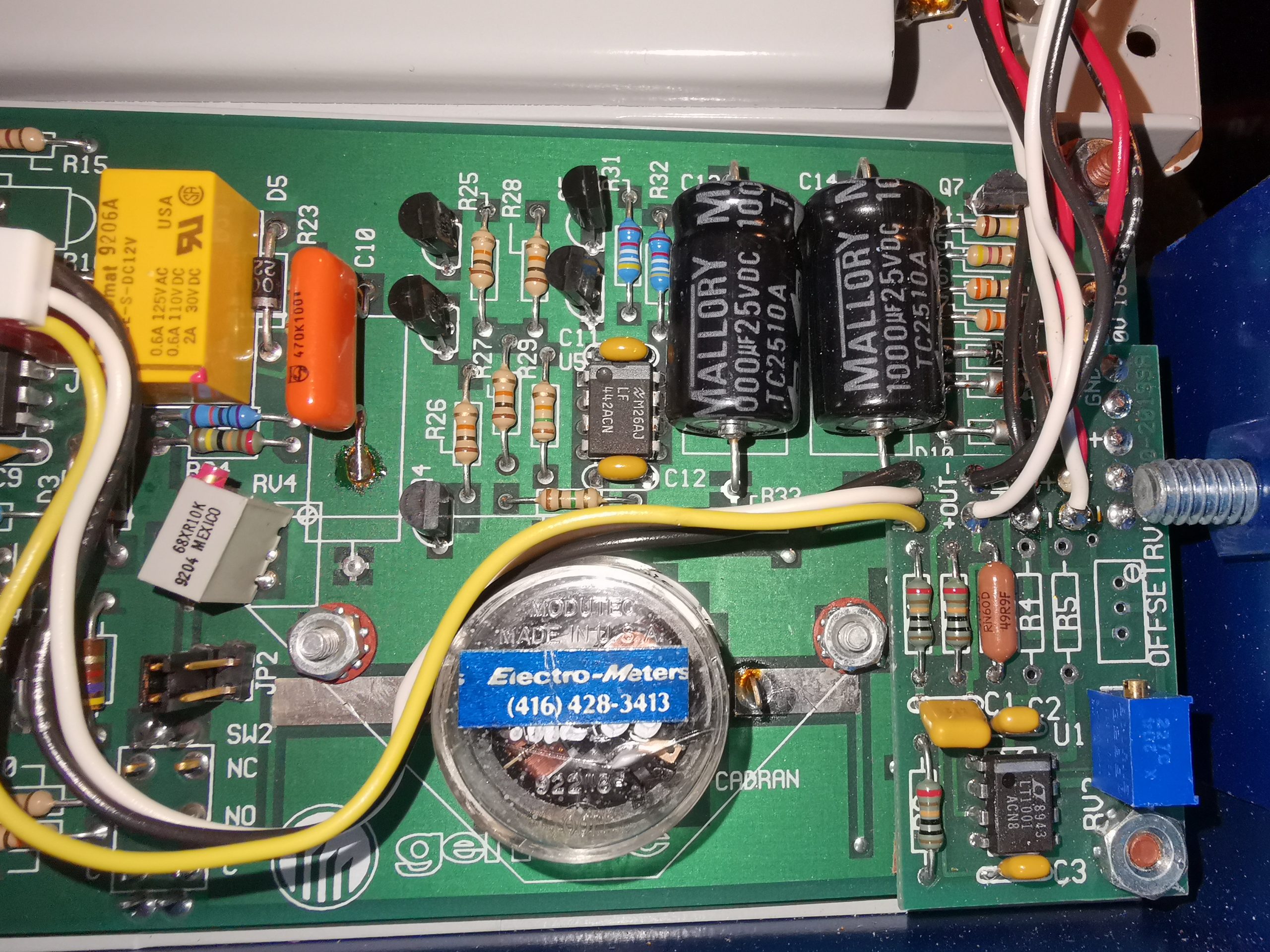
Taking the unit apart, with just 4 allen screws on the case reveals the mainboard. There’s very little back here! The active components are just Op-Amps – An OP07 ultralow offset in the bottom left corner is most likely the front-end amplifier, along with a few LF442ACN precision JFET input devices in the same area. The other amplifiers are LT1001 precision devices, with a 10mA output current capability. Most of the passives in this area are also high-stability & high precision parts.
The other side of the board handles the meter movement, and the power input section. There is a small daughterboard with another LT1001 Op-Amp on board, along with some passives, and the battery inputs go into here, however I’m not exactly sure what this is doing – there is another connection to the rear panel 1v analogue output BNC jack, so it may be the driver for that section. The 24v input is a single DC rail, however the 4 PP3 battery holders are wired as parallel pairs of batteries back to back, so a split +9v/-9v supply is generated.
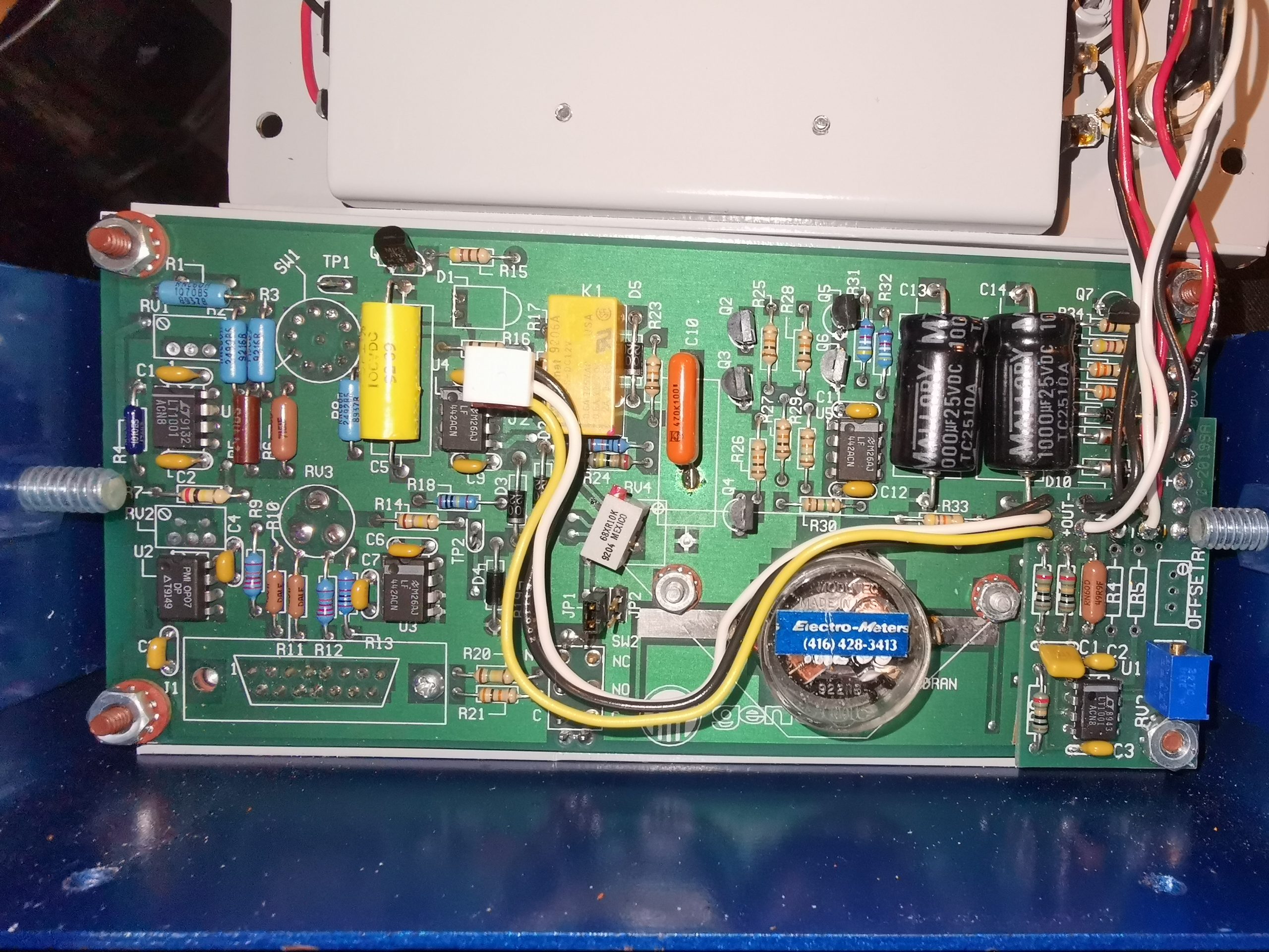
An overall view of the board shows the wiring back to the battery holder, 1v analogue output jack & DC input connector.

[…] thermopile sensors with TECs – but no way to verify any results until now. Since I have my Gentec meter to calibrate against, I can finally get on with the project. In the photo above, is the […]