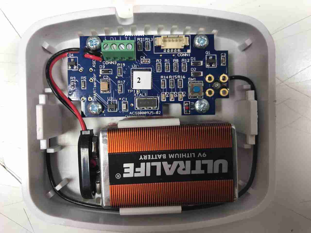
Here’s another random bit of RF tech, I’m told this is a wireless energy management sensor, however I wasn’t able to find anything similar on the interwebs. It’s powered by a standard 9v PP3 battery.
Microcontroller
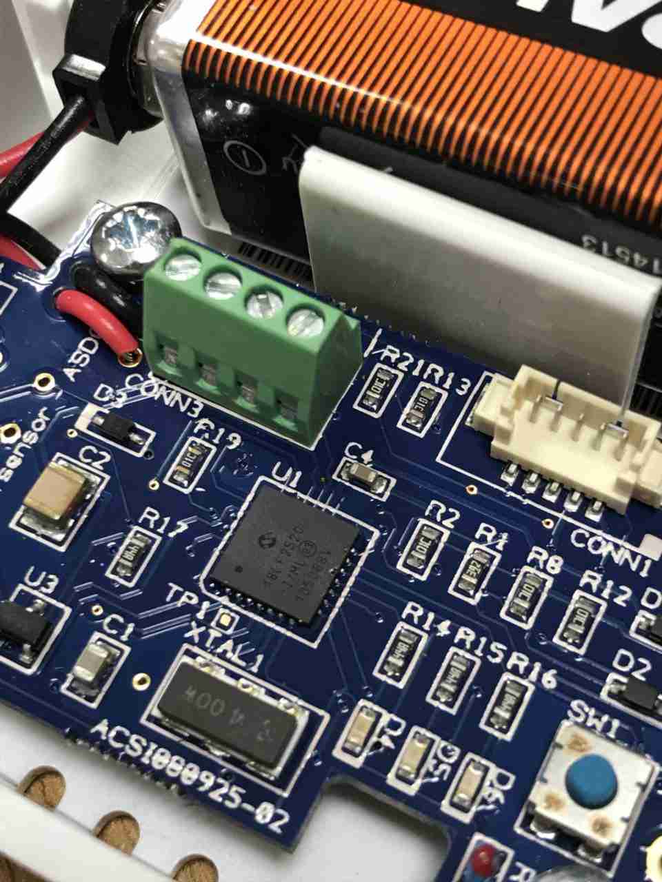
System control is handled by this Microchip PIC18F2520 Enhanced Flash microcontroller, this has an onboard 10-bit ADC & nanoWatt technology according to their datasheet. There’s a 4MHz crystal providing the clock, with a small SOT-23 voltage regulator in the bottom corner. There’s a screw terminal header & a plug header, but I’ve no idea what these would be used for. Maybe connecting an external voltage/current sensor & a programming header? The tactile button I imagine is for pairing the unit with it’s controller.
PCB Bottom
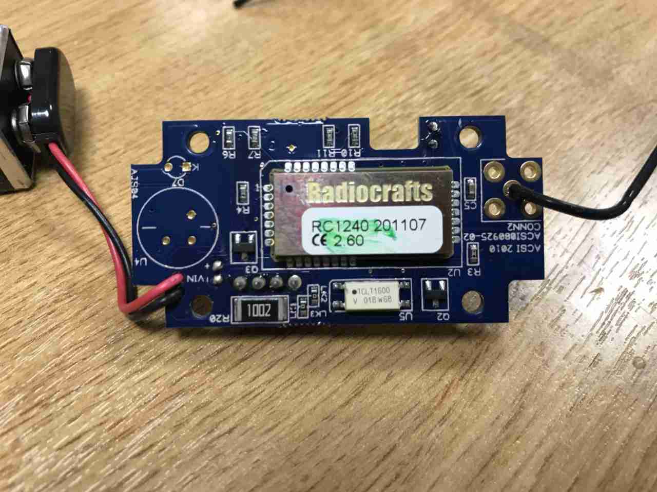
The bottom of the PCB is almost entirely taken up by a Radiocrafts RC1240 433MHz RF transceiver. Underneath there’s a large 10kΩ resistor, maybe a current transformer load resistor, and a TCLT1600 optocoupler. Just from the opto it’s clear this unit is intended to interface in some way to the mains grid. The antenna is connected at top right, in a footprint for a SMA connector, but this isn’t fitted.
During the rebuild of the wheelchair motors for the support trolley, I found myself needing an accurate milliohm meter to test the armature windings with. Commercial instruments like these are expensive, but some Google searching found a milliohm meter project based around the Arduino from Circuit Cellar.
Circuit Diagram
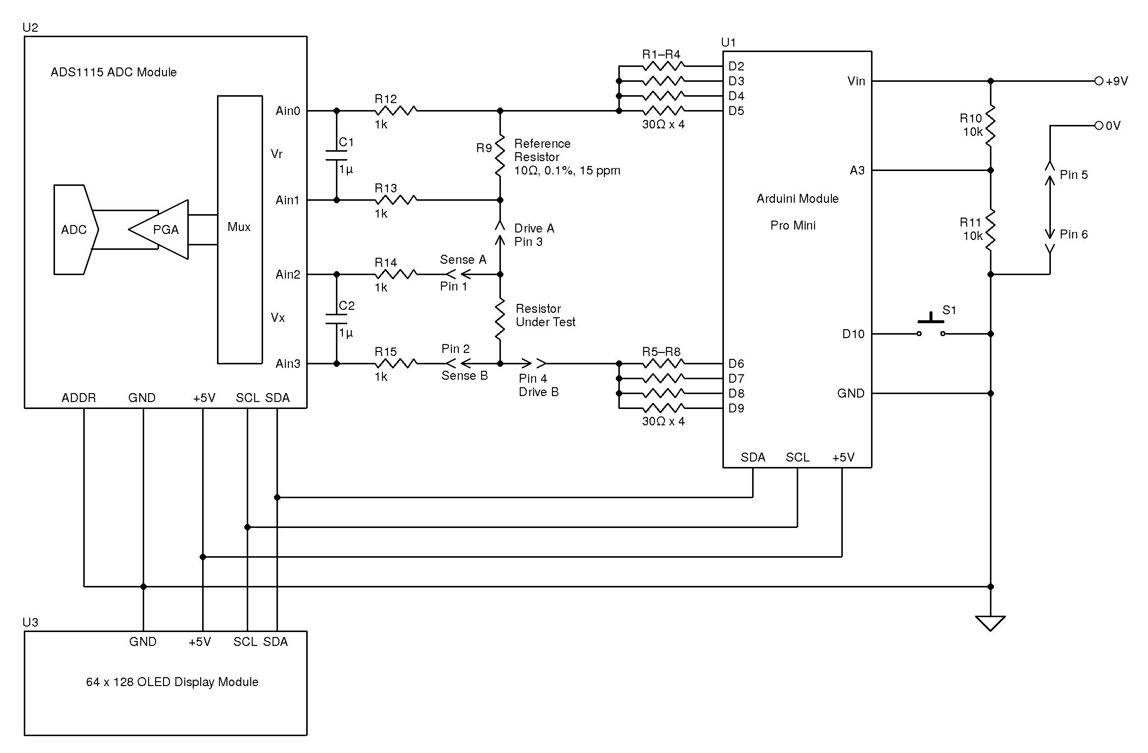
Here’s the original author’s circuit diagram, paralleling nearly all of the Arduino’s digital output pins together to source/sink the test current, an ADS1115 ADC to take more accurate readings, with the results displayed on a jellybean 128×64 OLED module. The most expensive part here is the 10Ω 0.1% 15ppm reference resistor, R9.
I decided to make some small adjustments to the power supply section of the project, to include a rechargeable lithium cell rather than a 9v PP3 battery. This required some small changes to the Arduino sketch, a DC-DC boost converter to supply 5v from the 3.7v of a lithium cell, a charger module for said cell, and with the battery voltage being within the input range of the analogue inputs, the voltage divider on A3 was removed. A new display icon was also added in to indicate when the battery is being charged, this uses another digital input pin for input voltage sensing.
I also made some basic changes to the way an unreadable resistance is displayed, showing “OL” instead of “—–“, and the meter sends the reading out over the I²C bus, for future expansion purposes. The address the data is directed to is set to 0x50.
I’ve not etched a PCB for this as I couldn’t be bothered with the messy etchant, so I built this on a matrix board instead.
Final Prototype
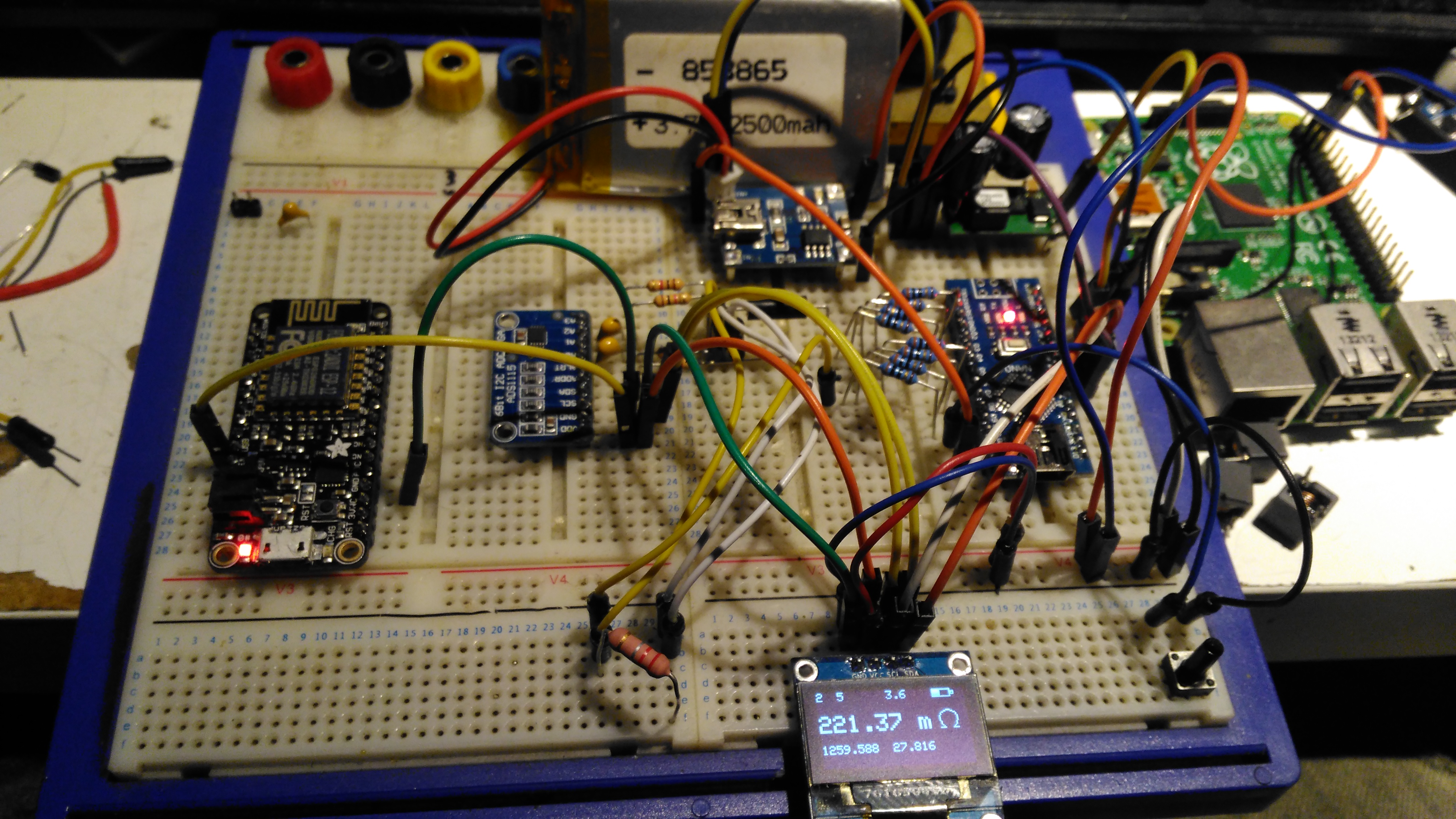
Since I made some changes to both the software and the hardware components, I decided to prototype the changes on breadboard. The lithium cell is at the top of the image. with the charger module & DC-DC converter. The Arduino Nano is on the right, the ADC & reference resistor on the left, and the display at the bottom.
The Raspberry Pi & ESP8266 module are being used in this case to discharge the battery quicker to make sure the battery level calibration was correct, and to make sure the DC-DC converter would continue to function throughout the battery voltage range.
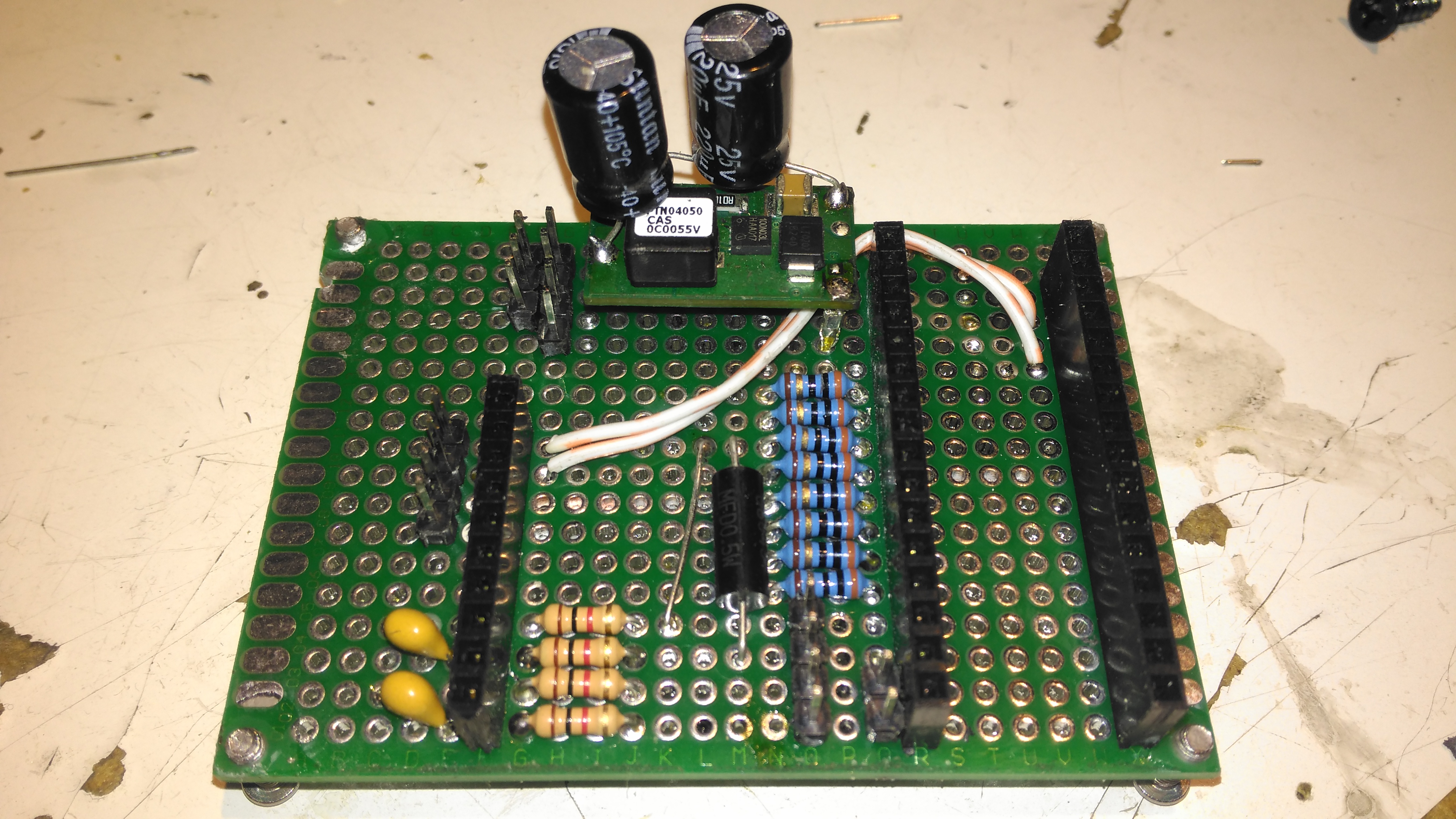
Matrix Board Passives
Here’s the final board with the passive components installed, along with the DC-DC converter. I used a Texas Instruments PTN04050 boost module for power as I had one spare.
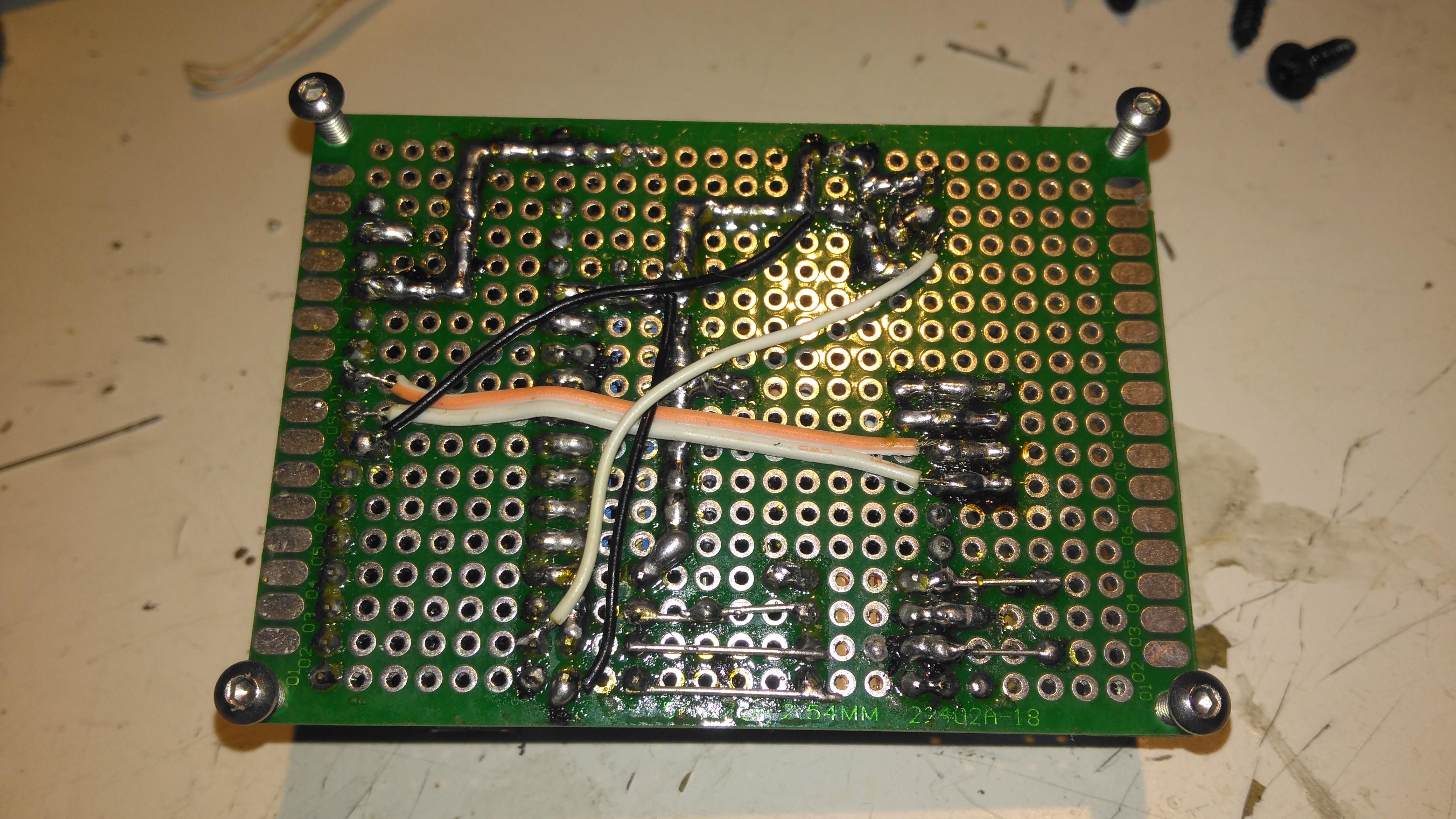
Matrix Board Rear
The bottom of the board has most of the wire jumpers for the I²C bus, and power sensing.
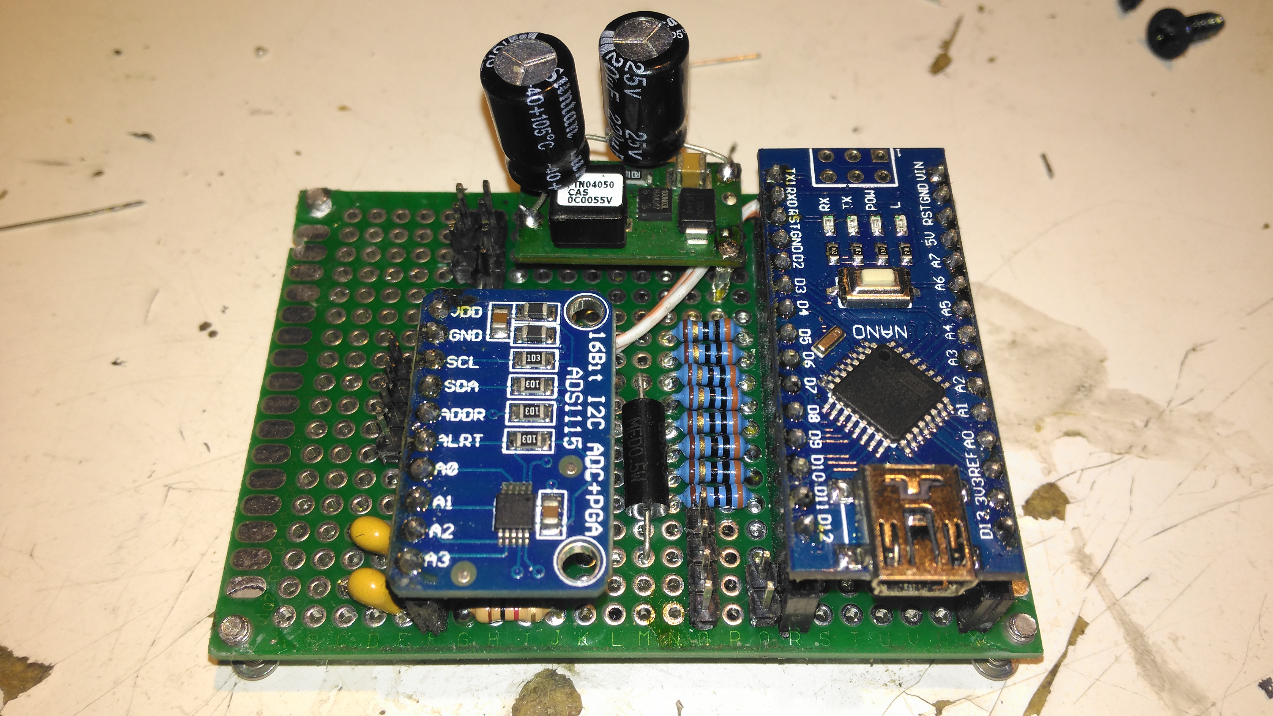
Matrix Board Modules
Here’s both modules installed on the board. I used an Arduino Nano instead of the Arduino Pro Mini that the original used as these were the parts I had in stock. Routing the analogue pins is also easier on the Mini, as they’re brought out to pins in the DIP footprint, instead of requiring wire links to odd spots on the module. To secure the PCB into the case without having to drill any holes, I tapped the corner holes of the matrix board M2.5 & threaded cap head screws in. These are then spot glued to the bottom of the case to secure the finished board.
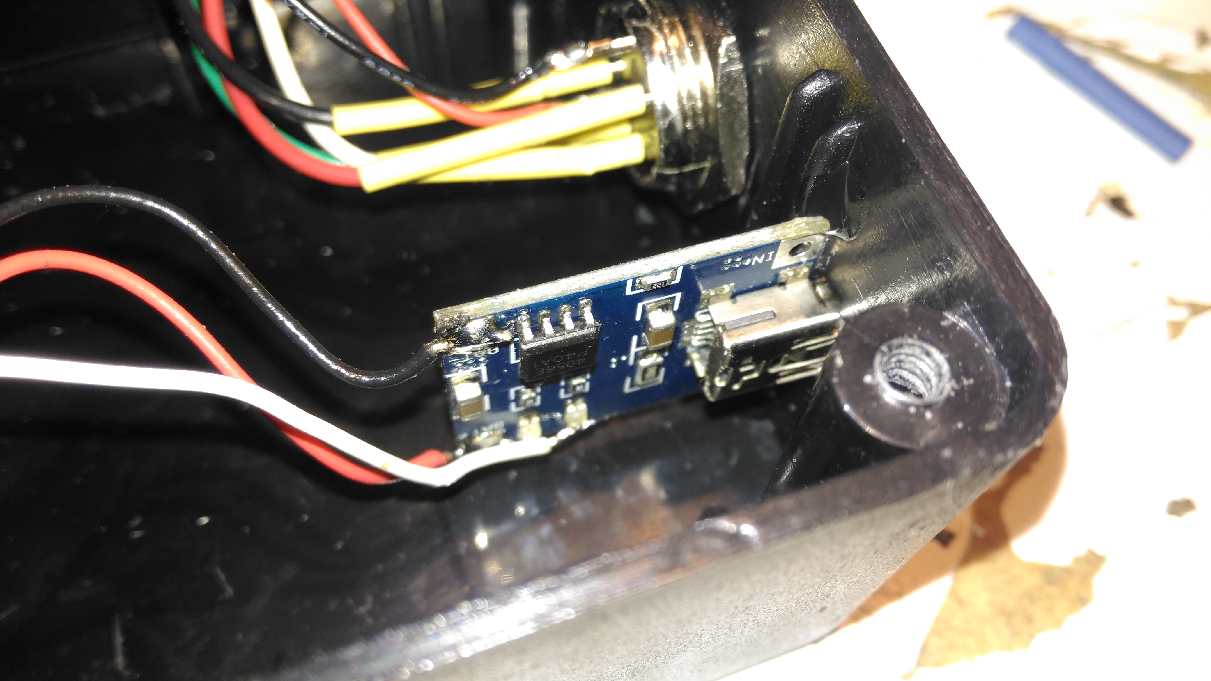
Lithium Charger
The lithium charger module is attached to the side of the enclosure, the third white wire is for input sensing – when the USB cable is plugged in a charge icon is shown on the OLED display.
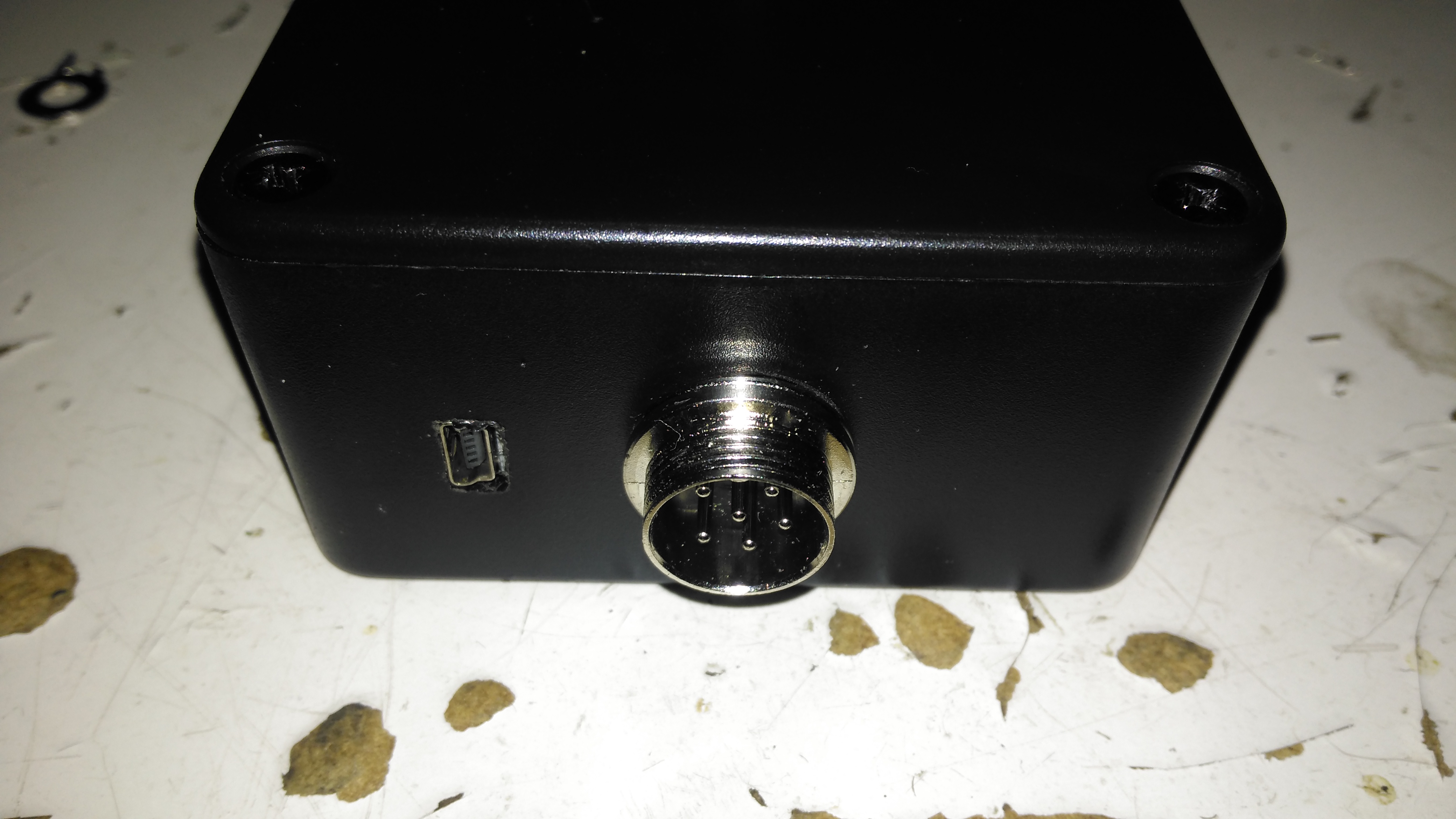
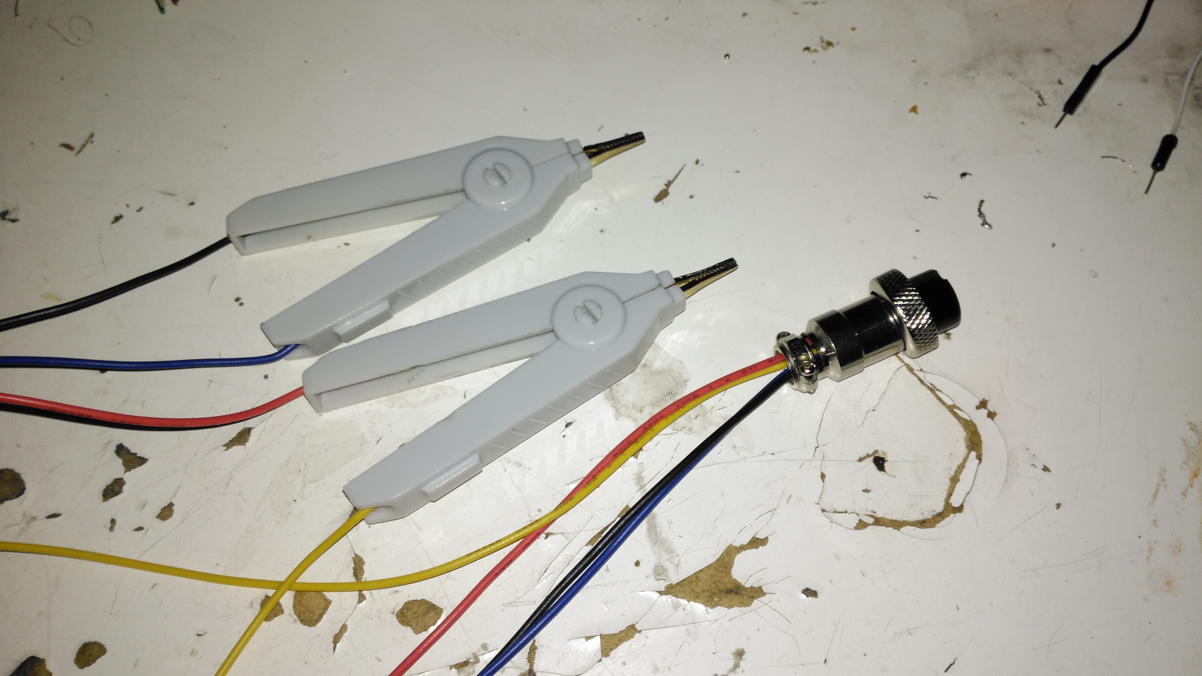
Input Connections
The inputs on the side of the enclosure. I’ve used the same 6-pin round connector for the probes, power is applied to the Arduino when the probes are plugged in.
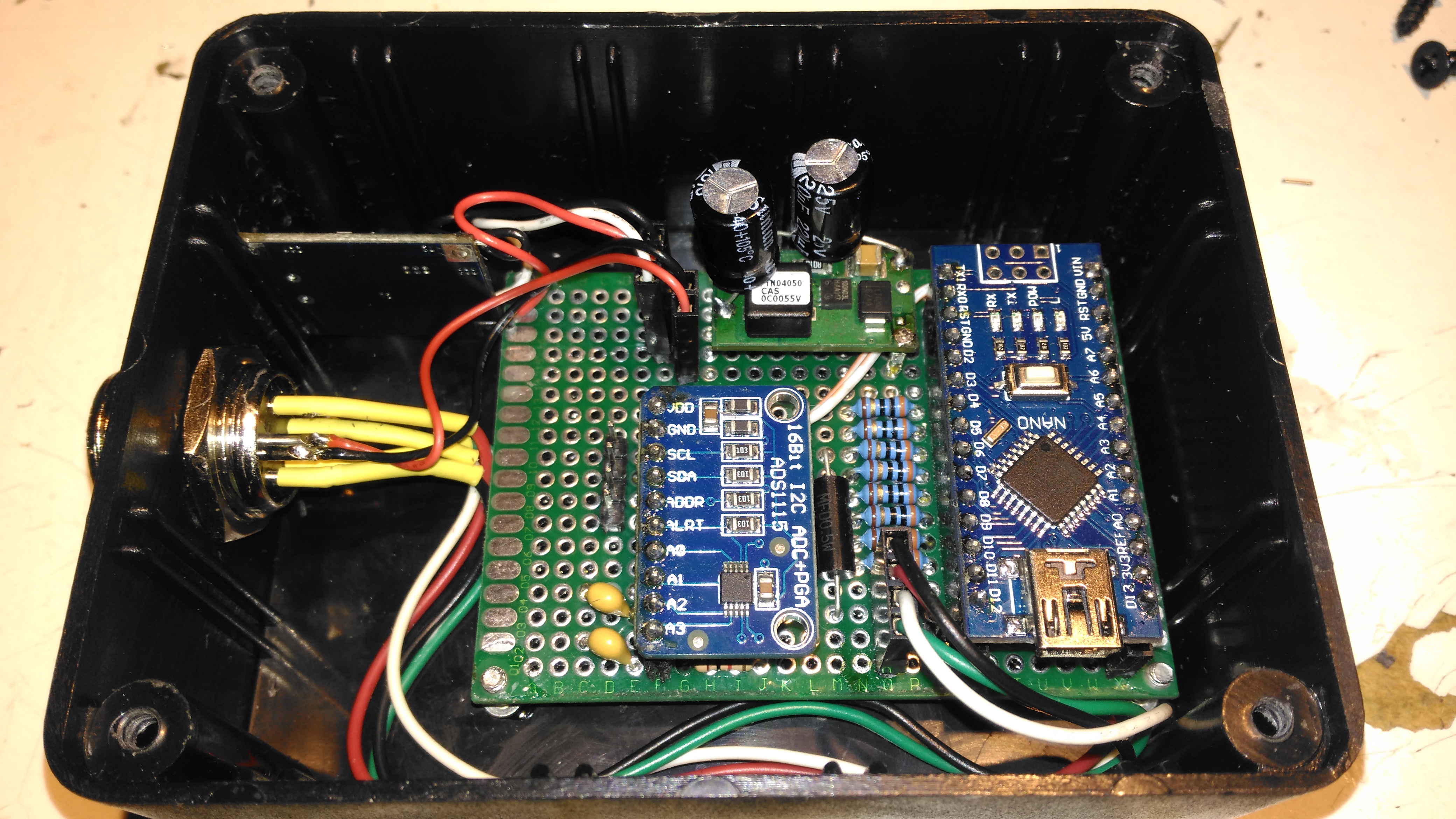
Module Installed
Everything installed in the enclosure – it’s a pretty tight fit especially with the lithium cell in place.
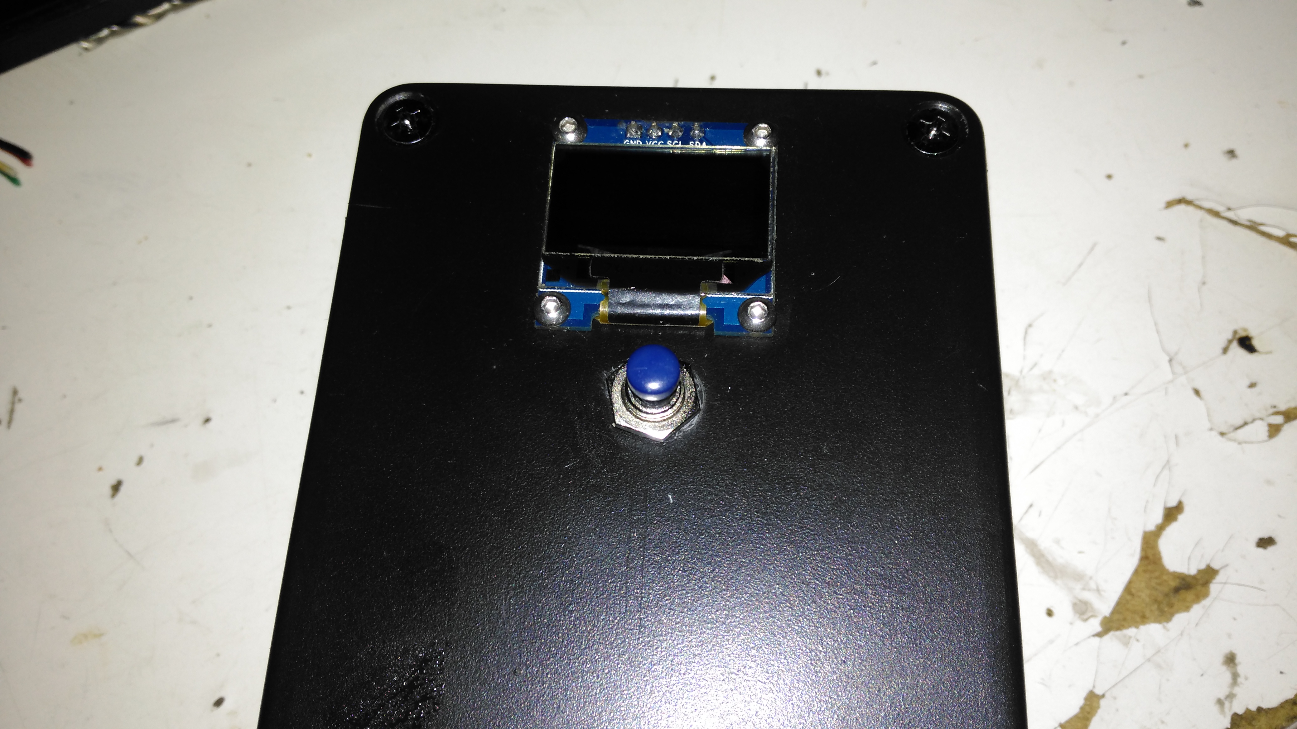
Meter Top Cover
The top cover has the Measure button, and the OLED display panel, the latter secured to the case with M2.5 cap head screws.
Kelvin Clips
Finally, the measurement loom, with Kelvin clips. These were an eBay buy, keeping things cheap. These clips seem to be fairly well built, even if the hinges are plastic. I doubt they’re actually gold-plated, more likely to be brass. I haven’t noticed any error introduced by these cheap clips so far.
The modified sketch is below:
// ---------------------------------------------------------------------------------------------
//  Simple, accurate milliohmeter
//
//  (c) Mark Driedger 2015
//
//  - Determines resistance using 4 wire measurement of voltage across a series connected
//  reference resistor (Rr, 10 ohm, 0.1%) and test resistor (Rx)
//  - range of accurate measurement is roughly 50 mohm to 10Kohm
//  - Uses Arduino digital I/O ports to deliver the test current, alternating polarity to cancel
//  offset errors (synchronous detector)
//  - 4 I/O pins are used for each leg of the test current to increase test current
//  - Averages 2 cycles and 100 samples/cycle
//  - Uses a 16 bit ADC ADS1115 with 16x PGA to improve accuracy
//
//  Version History
//    May 24/15    v1.0-v4.0
//      - initial development versions
//    May 27/15    v5.0
//      - changed display to I2C
//      - backed out low power module since it seemed to cause serial port upload problems
// ---------------------------------------------------------------------------------------------

#include <Wire.h>
#include <SPI.h>
#include <Adafruit_GFX.h>
#include <Adafruit_SSD1306.h>
//#include <LowPower.h>

#if (SSD1306_LCDHEIGHT != 64)
#error("Height incorrect, please fix Adafruit_SSD1306.h!");
#endif

// ---------------------------------------------------------------------------------------------
//  I/O port usage
// ---------------------------------------------------------------------------------------------
//    serial port (debug and s/w download)    0, 1
//    I²C interface to ADC & display          A4, A5
//    positive drive                          2, 3, 4, 5
//    push to test input                      8
//    unused                                  9, 10, 11, A0, A1, A2, A6, A7
//    negative drive                          6, 7, 8, 9
//    battery voltage monitor                 A3
//    debug output                            13

#define  P_PushToTest  10       // push button (measure), active low
#define  P_Debug       13
#define  CHG           12

//  ADS1115 mux and gain settings
#define  ADS1115_CH01  0x00    // p = AIN0, n = AIN1
#define  ADS1115_CH03  0x01    // ... etc
#define  ADS1115_CH13  0x02
#define  ADS1115_CH23  0x03
#define  ADS1115_CH0G  0x04    // p = AIN0, n = GND
#define  ADS1115_CH1G  0x05    // ... etc
#define  ADS1115_CH2G  0x06
#define  ADS1115_CH3G  0x07

#define  ADS1115_6p144  0x00   // +/- 6.144 V full scale
#define  ADS1115_4p096  0x01   // +/- 4.096 V full scale
#define  ADS1115_2p048  0x02   // +/- 2.048 V full scale
#define  ADS1115_1p024  0x03   // +/- 1.024 V full scale
#define  ADS1115_0p512  0x04   // +/- 0.512 V full scale
#define  ADS1115_0p256  0x05   // +/- 0.256 V full scale
#define  ADS1115_0p256B 0x06   // same as ADS1115_0p256
#define  ADS1115_0p256C 0x07   // same as ADS1115_0p256

Adafruit_SSD1306   display(0);               // using I2C interface, no reset pin
static int         debug_mode = 0;           // true in debug mode

float ADS1115read(byte channel, byte gain)
//--------------------------------------------------------------------------------------
//  reads a single sample from the ADS1115 ADC at a given mux (channel) and gain setting
//  - channel is 3 bit channel number/mux setting (one of ADS1115_CHxx)
//  - gain is 3 bit PGA gain setting (one of ADS1115_xpxxx)
//  - returns voltage in volts
//  - uses single shot mode, polling for conversion complete, default I2C address
//  - conversion takes approximatly 9.25 msec
//--------------------------------------------------------------------------------------
  {
  const int    address = 0x48;      // ADS1115 I2C address, A0=0, A1=0
  byte         hiByte, loByte;
  int          r;
  float        x;

  channel &= 0x07;                  // constrain to 3 bits
  gain    &= 0x07;

  hiByte = B10000001 | (channel<<4) | (gain<<1);    // conversion start command
  loByte = B10000011;

  Wire.beginTransmission(address);  // send conversion start command
  Wire.write(0x01);                 // address the config register
  Wire.write(hiByte);               // ...and send config register value
  Wire.write(loByte);
  Wire.endTransmission();

   do                               // loop until conversion complete
    {
    Wire.requestFrom(address, 2);   // config register is still addressed
    while(Wire.available())
      {
      hiByte = Wire.read();         // ... and read config register
      loByte = Wire.read();
      }
    }
  while ((hiByte & 0x80)==0);       // upper bit (OS) is conversion complete

  Wire.beginTransmission(address);
  Wire.write(0x00);                 // address the conversion register
  Wire.endTransmission();

  Wire.requestFrom(address, 2);     // ... and get 2 byte result
  while(Wire.available())
    {
    hiByte = Wire.read();
    loByte = Wire.read();
    }

  r = loByte | hiByte<<8;           // convert to 16 bit int
  switch(gain)                      // ... and now convert to volts
    {
      case ADS1115_6p144:  x = r * 6.144 / 32768.0; break;
      case ADS1115_4p096:  x = r * 4.096 / 32768.0; break;
      case ADS1115_2p048:  x = r * 2.048 / 32768.0; break;
      case ADS1115_1p024:  x = r * 1.024 / 32768.0; break;
      case ADS1115_0p512:  x = r * 0.512 / 32768.0; break;
      case ADS1115_0p256:
      case ADS1115_0p256B:
      case ADS1115_0p256C: x = r * 0.256 / 32768.0; break;
    }
  return x;
  }

// ---------------------------------------------------------------------------------------------
//  Drive functions
//   - ports 4-7 and A0-A3 are used to differentially drive resistor under test
//   - the ports are resistively summed to increase current capability
//   - DriveOff() disables the drive, setting the bits to input
//   - DriveOn()  enables the drive,  setting the bits to output
//   - DriveP()   enables drive with positive current flow (from ports 4-7 to ports A0-A3)
//   - DriveN()   enables drive with negative current flow
// ---------------------------------------------------------------------------------------------
void DriveP()
  {
    DriveOff();
    digitalWrite( 2, HIGH);
    digitalWrite( 3, HIGH);
    digitalWrite( 4, HIGH);
    digitalWrite( 5, HIGH);
    digitalWrite( 6, LOW);
    digitalWrite( 7, LOW);
    digitalWrite( 8, LOW);
    digitalWrite( 9, LOW);
    DriveOn();
  }

void DriveN()
  {
    DriveOff();
    digitalWrite( 2, LOW);
    digitalWrite( 3, LOW);
    digitalWrite( 4, LOW);
    digitalWrite( 5, LOW);
    digitalWrite( 6, HIGH);
    digitalWrite( 7, HIGH);
    digitalWrite( 8, HIGH);
    digitalWrite( 9, HIGH);
    DriveOn();
  }

void DriveOn()
  {
    pinMode( 2, OUTPUT);      // enable source/sink in pairs
    pinMode( 6, OUTPUT);
    pinMode( 3, OUTPUT);
    pinMode( 7, OUTPUT);
    pinMode( 4, OUTPUT);
    pinMode( 8, OUTPUT);
    pinMode( 5, OUTPUT);
    pinMode( 9, OUTPUT);
    delayMicroseconds(5000);  // 5ms delay
  }

void DriveOff()
  {
    pinMode( 2, INPUT);       // disable source/sink in pairs
    pinMode( 6, INPUT);
    pinMode( 3, INPUT);
    pinMode( 7, INPUT);
    pinMode( 4, INPUT);
    pinMode( 8, INPUT);
    pinMode( 5, INPUT);
    pinMode( 9, INPUT);
  }

int CalcPGA(float x)
// ---------------------------------------------------------------------------------------------
//   Calculate optimum PGA setting based on a sample voltage, x, read at lowest PGA gain
//     - returns the highest PGA gain that allows x to be read with 10% headroom
// ---------------------------------------------------------------------------------------------
  {
    x = abs(x);
    if (x>3.680) return ADS1115_6p144;
    if (x>1.840) return ADS1115_4p096;
    if (x>0.920) return ADS1115_2p048;
    if (x>0.460) return ADS1115_1p024;
    if (x>0.230) return ADS1115_0p512;
    else         return ADS1115_0p256;
  }

void BatteryIcon(float charge)
// ---------------------------------------------------------------------------------------------
//   Draw a battery charge icon into the display buffer without refreshing the display
//     - charge ranges from 0.0 (empty) to 1.0 (full)
// ---------------------------------------------------------------------------------------------
  {
    static const unsigned char PROGMEM chg[] =     // Battery Charge Icon
    { 0x1c, 0x18, 0x38, 0x3c, 0x18, 0x10, 0x20, 0x00 };

    int w = constrain(charge, 0.0, 1.0)*16;  // 0 to 16 pixels wide depending on charge
    display.drawRect(100, 0, 16, 7, WHITE);  // outline
    display.drawRect(116, 2,  3, 3, WHITE);  // nib
    display.fillRect(100, 0,  w, 7, WHITE);  // charge indication

    //battery charging indication
    pinMode(CHG, INPUT);
    if (digitalRead(CHG) == HIGH)
      display.drawBitmap(91, 0, chg, 8, 8, WHITE);
  }

void f2str(float x, int N, char *c)
// ---------------------------------------------------------------------------------------------
//    Converts a floating point number x to a string c with N digits of precision
//     - *c must be a string array of length at least N+3 (N + '-', '.', '\0')
//     - x must be have than N leading digits (before decimal) or "#\0" is returned
// ---------------------------------------------------------------------------------------------
  {
  int     j, k, r;
  float   y;

  if (x<0.0)                    // handle negative numbers
    {
      *c++ = '-';
      x = -x;
    }
  for (j=0; x>=1.0; j++)        // j digits before decimal point
    x /= 10.0;                  // .. and scale x to be < 1.0

  if (j>N)                      // return error string if too many digits
    {
      *c++ = '#';
      *c++ = '\0';
      return;
    }

  y = pow(10, (float) N);       // round to N digits
  x = round(x * y) / y;
  if (x>1.0)                    // if 1st digit rounded up ...
    {
      x /= 10.0;                // then normalize back down 1 digit
      j++;
    }

  for (k=0; k<N; k++)
    {
      r = (int) (x*10.0);        // leading digit as int
      x = x*10-r;                // remove leading digit and shift 1 digit

      *c++ = r + '0';            // add leading digit to string
      if (k==j-1 && k!=N-1)      // add decimal point after j digits
        *c++ = '.';              // ... unless there are N digits before decimal
    }
  *c++ = '\0';
  }

void DisplayResistance(float x)
// ---------------------------------------------------------------------------------------------
//    Adds the resistance value, x, to the display buffer without refreshing the display
//      - converts to kohm, milliohm or microohm if necessary
// ---------------------------------------------------------------------------------------------
  {
    static const unsigned char PROGMEM omega_bmp[] =     // omega (ohm) symbol
    { B00000011, B11000000,
      B00001100, B00110000,
      B00110000, B00001100,
      B01000000, B00000010,
      B01000000, B00000010,
      B10000000, B00000001,
      B10000000, B00000001,
      B10000000, B00000001,
      B10000000, B00000001,
      B10000000, B00000001,
      B01000000, B00000010,
      B01000000, B00000010,
      B01000000, B00000010,
      B00100000, B00000100,
      B00010000, B00001000,
      B11111000, B00011111 };

    char  s[8];
    char  prefix;

    if (x>=1000.0)          // display in killo ohms
      {
        x /= 1000.0;
        prefix = 'k';
      }
    else if (x<0.001)       // display in micro ohms
      {
        x *= 1000000.0;
        prefix = 0xe5;    // mu
      }
    else if (x<1.0)         // display in milli ohms
      {
        x *= 1000.0;
        prefix = 'm';
      }
    else
      prefix = ' ';         // display in ohms

    f2str(x, 5, s);

    // display computed resistance
    display.setTextSize(2);
    display.setTextColor(WHITE);
    display.setCursor(0,20);
    display.print(s);

    // display prefix
    display.setCursor(85,20);
    display.print(prefix);

    // display omega (ohms) symbol
    display.drawBitmap(103, 18, omega_bmp, 16, 16, WHITE);
  }

void DisplayDebug(int a, int b, float x, float y, float Vbat)
// ---------------------------------------------------------------------------------------------
//    Adds debug info to the display buffer without showing the updated display
//      - Adds 2 ints (a, b) and a float(Vbat) to the top line and 2 floats (x, y)
//      to the bottom line+, all in small (size 1) text
// ---------------------------------------------------------------------------------------------
  {
    // display x, y in lower left, small font
    display.setTextSize(1);
    display.setCursor(0,45);
    display.print(x,3);
    display.print("  ");
    display.print(y,3);

    // display a, b in upper left, small font
    display.setTextSize(1);
    display.setCursor(0,0);
    display.print(a);
    display.print("  ");
    display.print(b);

    // display Vbat in upper middle, small font
    display.setTextSize(1);
    display.setCursor(60,0);
    display.print(Vbat,1);
  }

void DisplayStr(char *s)
// ---------------------------------------------------------------------------------------------
//    Adds a string, s, to the display buffer without refreshing the display @ (0,20)
// ---------------------------------------------------------------------------------------------
  {
    display.setTextSize(2);
    display.setTextColor(WHITE);
    display.setCursor(8,20);
    display.print(s);
  }

#ifdef TESTMODE
void loop()
  {
    while (digitalRead(P_PushToTest))
      ;
    DriveP();
    display.clearDisplay();
    DisplayStr("Drive: +");
    display.display();
    delay(250);

    while (digitalRead(P_PushToTest))
      ;
    DriveN();
    display.clearDisplay();
    DisplayStr("Drive: -");
    display.display();
    delay(250);

    while (digitalRead(P_PushToTest))
      ;
    DriveOff();
    display.clearDisplay();
    DisplayStr("Drive: Off");
    display.display();
    delay(250);
  }
#endif

void setup()
// ---------------------------------------------------------------------------------------------
//    - initializae display and I/O ports
// ---------------------------------------------------------------------------------------------
  {
    DriveOff();                                    // disable current drive
    Wire.begin();                                  // join I2C bus
    display.begin(SSD1306_SWITCHCAPVCC, 0x3c, 0);  // initialize display @ address 0x3c, no reset
    pinMode(P_PushToTest, INPUT_PULLUP);           // measure push button switch, active low
    debug_mode = !digitalRead(P_PushToTest);       // if pushed during power on, then debug mode
    pinMode(P_Debug, OUTPUT);                      // debug port
  }

void loop()
// ---------------------------------------------------------------------------------------------
//    main measurement loop
// ---------------------------------------------------------------------------------------------
  {
    const float      Rr = 10.0;             // reference resistor value, ohms
    const float      Rcal = 1.002419;       // calibration factor
    const int        N = 2;                 // number of cycles to average
    const int        M = 50;                // samples per half cycle
    static long      Toff;
    double           Rx;                    // calculated resistor under test, ohms
    byte             PGAr, PGAx;            // PGA gains (r = reference, x = test resistors)
    float            Vr, Vx, Wx, Wr;        // voltages in V
    float            Rn;                    // calculated resistor under test, ohms, single sample
    double           Avgr, Avgx;            // average ADC readings in mV
    int              j, k, n;
    float            Vbat;                  // battery voltage in V (from 2:1 divider)
    char             serialbuff[10];        // Buffer for sending the reading over I²C

    display.clearDisplay();
    DisplayStr("measuring");
    display.display();

    // determine PGA gains
    DriveP();
    Wr =  ADS1115read(ADS1115_CH01, ADS1115_6p144);
    Wx =  ADS1115read(ADS1115_CH23, ADS1115_6p144);
    DriveN();
    Vr = -ADS1115read(ADS1115_CH01, ADS1115_6p144);
    Vx = -ADS1115read(ADS1115_CH23, ADS1115_6p144);

    //  measure battery voltage ... while drive is on so there is a load
    Vbat = analogRead(A3)*5.0/1024.0;    // 2:1 divider (5V FS) on 4.2v lithium battery

    DriveOff();

    PGAr = CalcPGA(max(Vr, Wr));           // determine optimum PGA gains
    PGAx = CalcPGA(max(Vx, Wx));

    // measure resistance using synchronous detection
    Avgr = Avgx = 0.0;                     // clear averages
    Rx = 0.0;
    n = 0;
    for (j=0; j<N; j++)                    // for each cycle
      {
        DriveP();                          // turn on drive, positive
        for (k=0; k<M; k++)
          {
            digitalWrite(P_Debug, 1);
            Vx = ADS1115read(ADS1115_CH23, PGAx);
            digitalWrite(P_Debug, 0);
            Vr = ADS1115read(ADS1115_CH01, PGAr);
            Avgx += Vx;
            Avgr += Vr;
            Rn = Vx/Vr;
            if (Rn>0.0 && Rn<10000.0)
              {
              Rx += Rn;
              n++;
              }
          }

        DriveN();                          // turn on drive, negative
        for (k=0; k<M; k++)
          {
            digitalWrite(P_Debug, 1);
            Vx = ADS1115read(ADS1115_CH23, PGAx);
            digitalWrite(P_Debug, 0);
            Vr = ADS1115read(ADS1115_CH01, PGAr);
            Avgx -= Vx;
            Avgr -= Vr;
            Rn = Vx/Vr;
            if (Rn>0.0 && Rn<10000.0)
              {
              Rx += Rn;
              n++;
              }
          }
      }

    DriveOff();
    Rx   *= Rr * Rcal / n;                 // apply calibration factor and compute average
    Avgr *= 1000.0 / (2.0*N*M);            // average in mV
    Avgx *= 1000.0 / (2.0*N*M);

    // display the results ... battery icon, Rx measurement, debug info if requested
    display.clearDisplay();                // ... and display result
    BatteryIcon((Vbat-3.0)/(4.2-3.0));     // 7.5V = 0%, 9V = 100%
    //display.drawLine(0, 8, 127, 8, WHITE); //Draw separator line under icons
    if (n==0){                              // no measurement taken ...
      display.setTextSize(2);
      display.setCursor(51,20);
      display.print(F("OL"));
    }
      //DisplayStr("-----");
    else
      DisplayResistance(Rx);
    //Send Reading via I²C
      Wire.beginTransmission(0x50);
      Wire.write(dtostrf(Rx, 5, 5, serialbuff));
      Wire.endTransmission();
    if (debug_mode)
      DisplayDebug(PGAr, PGAx, Avgr, Avgx, Vbat);
    display.display();                     // show the display

    // and then wait for next measurement request
    Toff = millis()+60000L;
    while(digitalRead(P_PushToTest))       // loop until measure button pressed
      {
        // Enter power down state for 120ms with ADC and BOD module disabled
        //LowPower.powerDown(SLEEP_120MS, ADC_OFF, BOD_OFF);
        if (millis()>Toff)                 // after 7 seconds ...
          {
            display.clearDisplay();        // clear display
            display.display();
          }
      }
  }
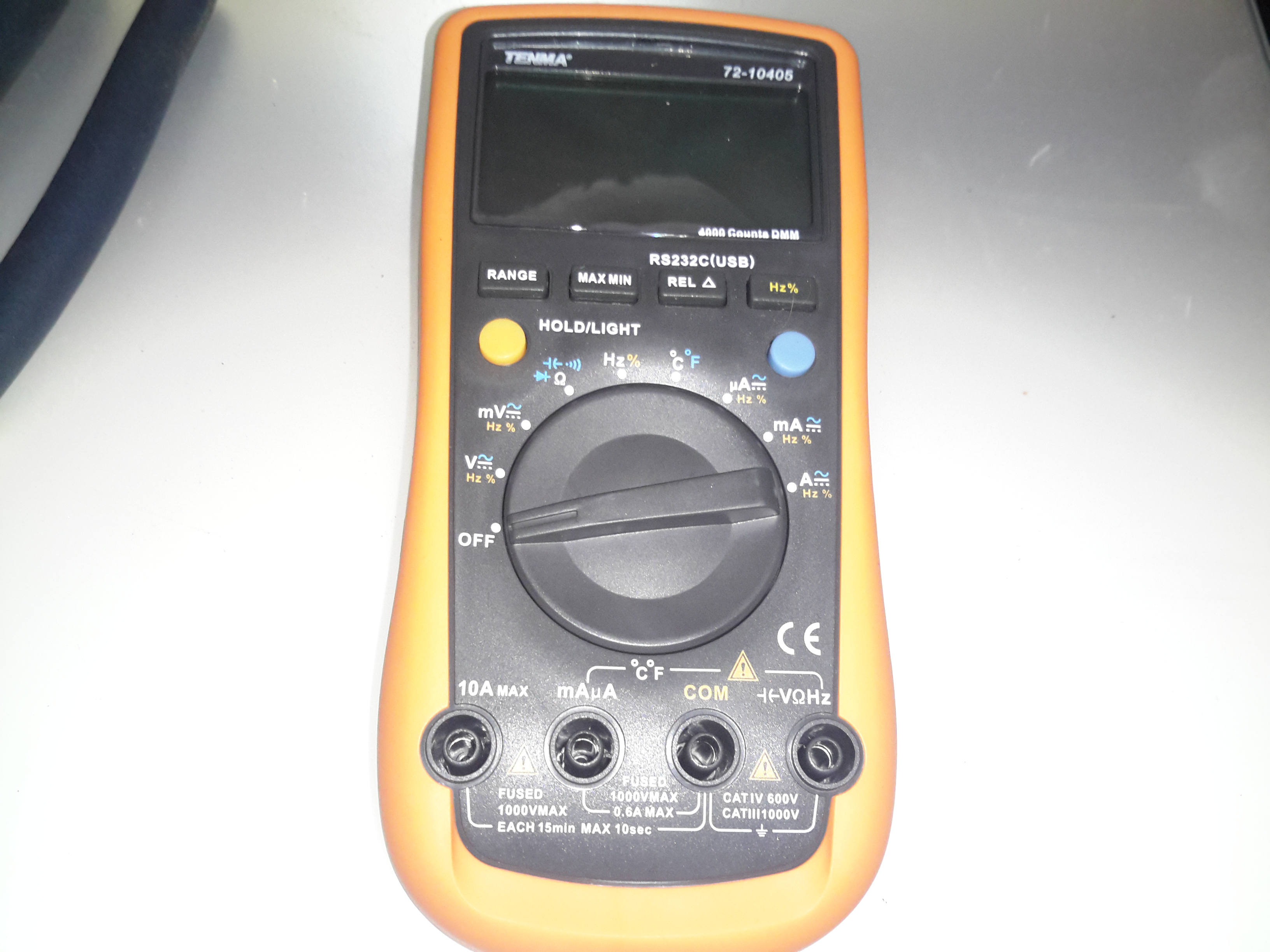
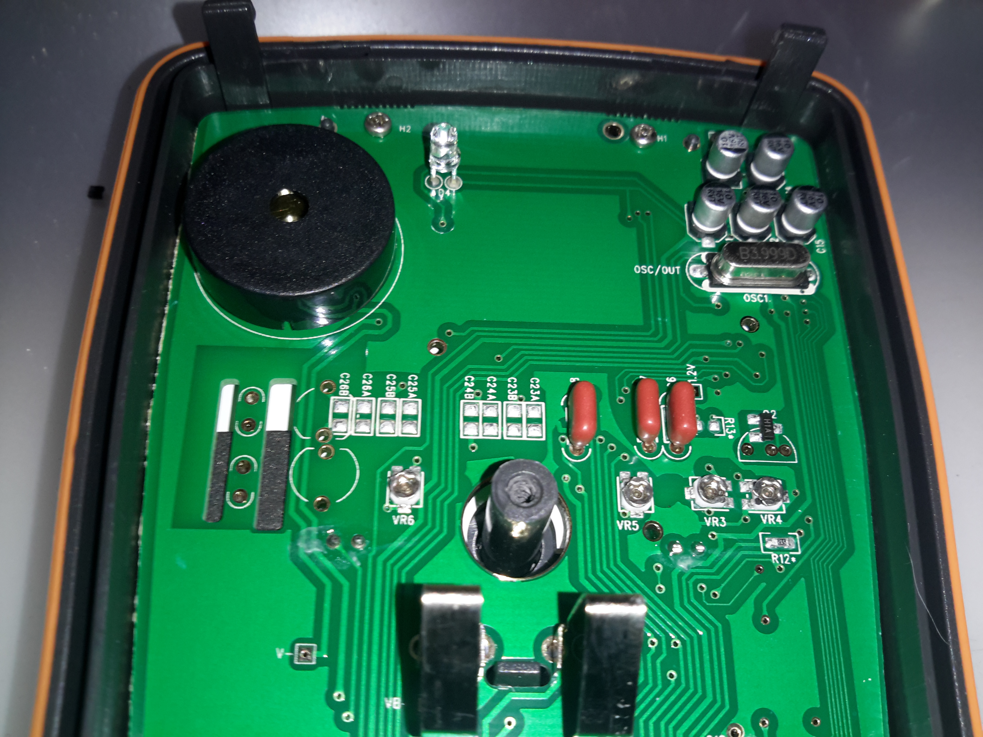
Well it’s time for a new DMM. After the last pair of eBay El-Cheapo Chinese meters just didn’t last very well, I decided a proper meter was required. This one is a Tenma 72-10405, stocked by Farnell for under £60. Not quite as many festures as the cheapo Chinese meters, but I expect this one to be a bit more reliable.
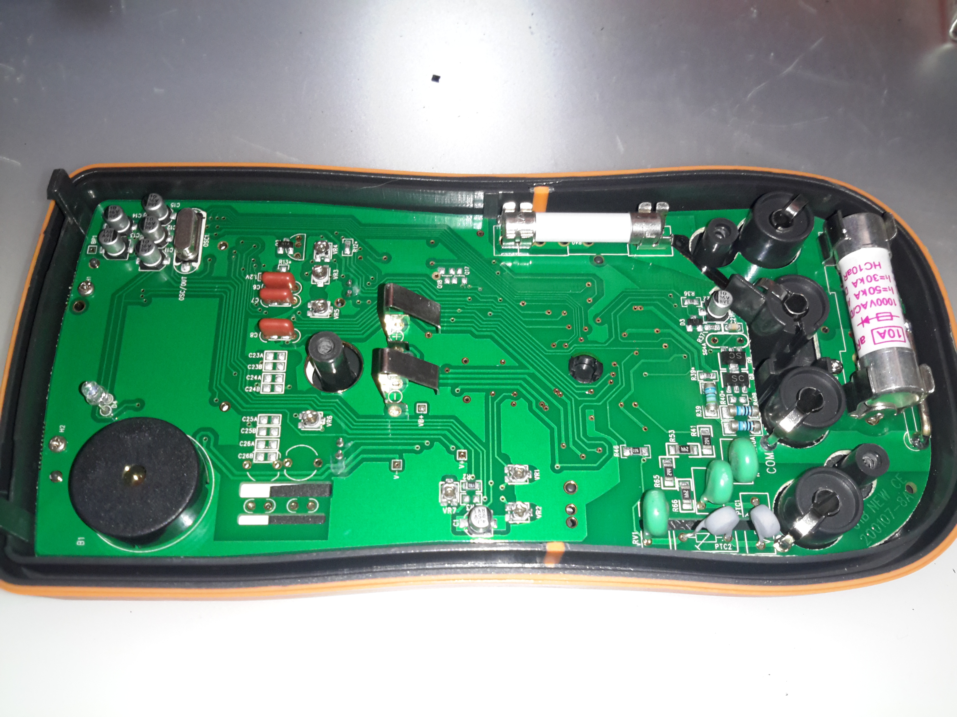
PCB Rear
Since I can’t have anything without seeing how it’s put together, here’s the inside of the DMM. (Fuse access is only possible by taking the back cover off as well. The 9v PP3 battery has a seperate cover).
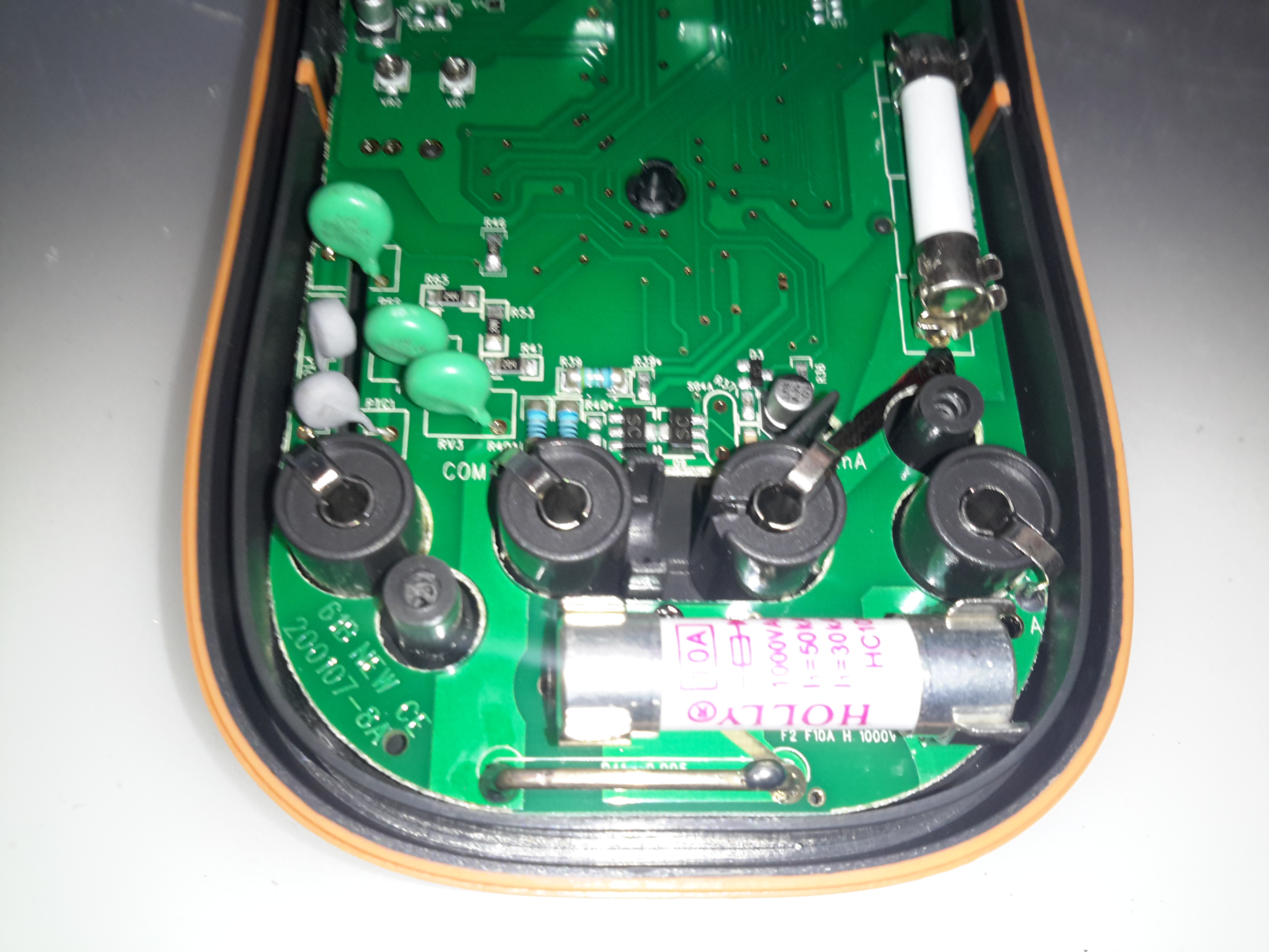
PCB Rear Bottom
He’s the input section of the meter, with the 10A HRC fuse & current shunt for the high-amps range. The other fuse above is for the mA/µA ranges. The back cover has a wide lip around the edge, that slots into a recess in the front cover, presumably for blast protection if the meter should meet a sticky end. The HRC fuses are a definite improvement over the cheap DMMs, they only have 15mm glass fuses, and no blast protection built into the casing.
There are some MOVs for input protection on the volts/ohms jack, the jacks themselves are nothing more than stampings though.
PCB Rear Top
Not much at the other side of the board, there’s the IR LED for the RS232 interface & the beeper.
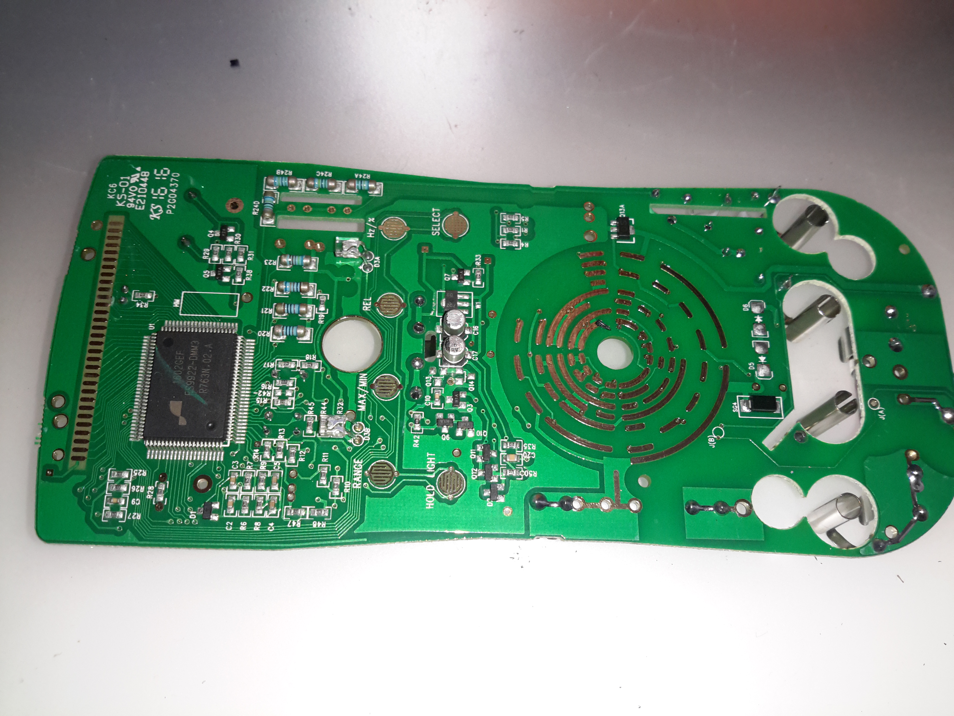
PCB Front
Most of the other components are on the other side of the PCB under the LCD display. The range switch is in the centre, while the main chipset is on the left.
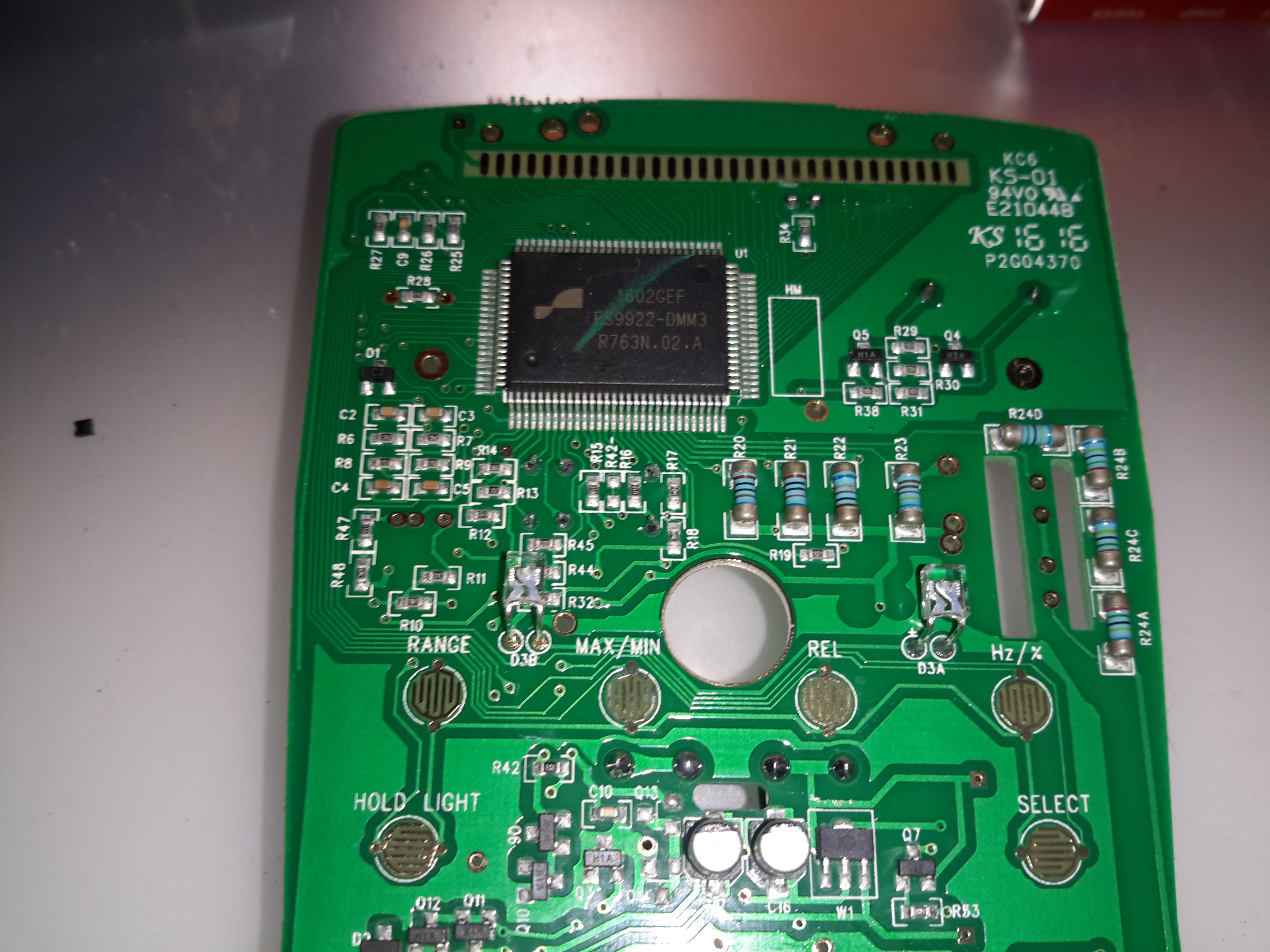
DMM Chipset
The chipset of this meter is a FS9922-DMM3 from Fortune Semiconductor, this is a dedicated DMM chipset with built in ADCs & microcontroller.
Here’s a quick look at a Sainsmart frequency counter module. These are useful little gadgets, showing the locked frequency on a small LCD display.
It’s built around an ATMega328 microcontroller (µC), and an MB501L Prescaler IC. The circuit for this is very simple, and is easily traced out from the board.
Frequency Counter
Here’s the back of the board, with the µC on the left & the prescaler IC on the right. This uses a rather novel method for calibration, which is the trimmer capacitor next to the crystal. This trimmer varies the frequency of the µC’s oscillator, affecting the calibration.
Input protection is provided by a pair of 1N4148 diodes in inverse parallel. These will clamp the input to +/-1v.
The prescaler IC is set to 1/64 divide ratio. This means that for an input frequency of 433MHz, it will output a frequency of 6.765625MHz to the µC.
The software in the µC will then calculate the input frequency from this intermediate frequency. This is done because the ATMega controllers aren’t very cabable of measuring such high frequencies.
The calculated frequency is then displayed on the LCD. This is a standard HD44780 display module.
LCD
Power is provided by a 9v PP3 battery, which is then regulated down by a standard LM7805 linear regulator.
Readout
I’ve found it’s not very accurate at all at the lower frequencies, when I fed it 40MHz from a signal generator it displayed a frequency of around 74MHz. This is probably due to the prescaler & the software not being configured for such a low input. In the case for 40MHz input the scaled frequency would have been 625kHz.
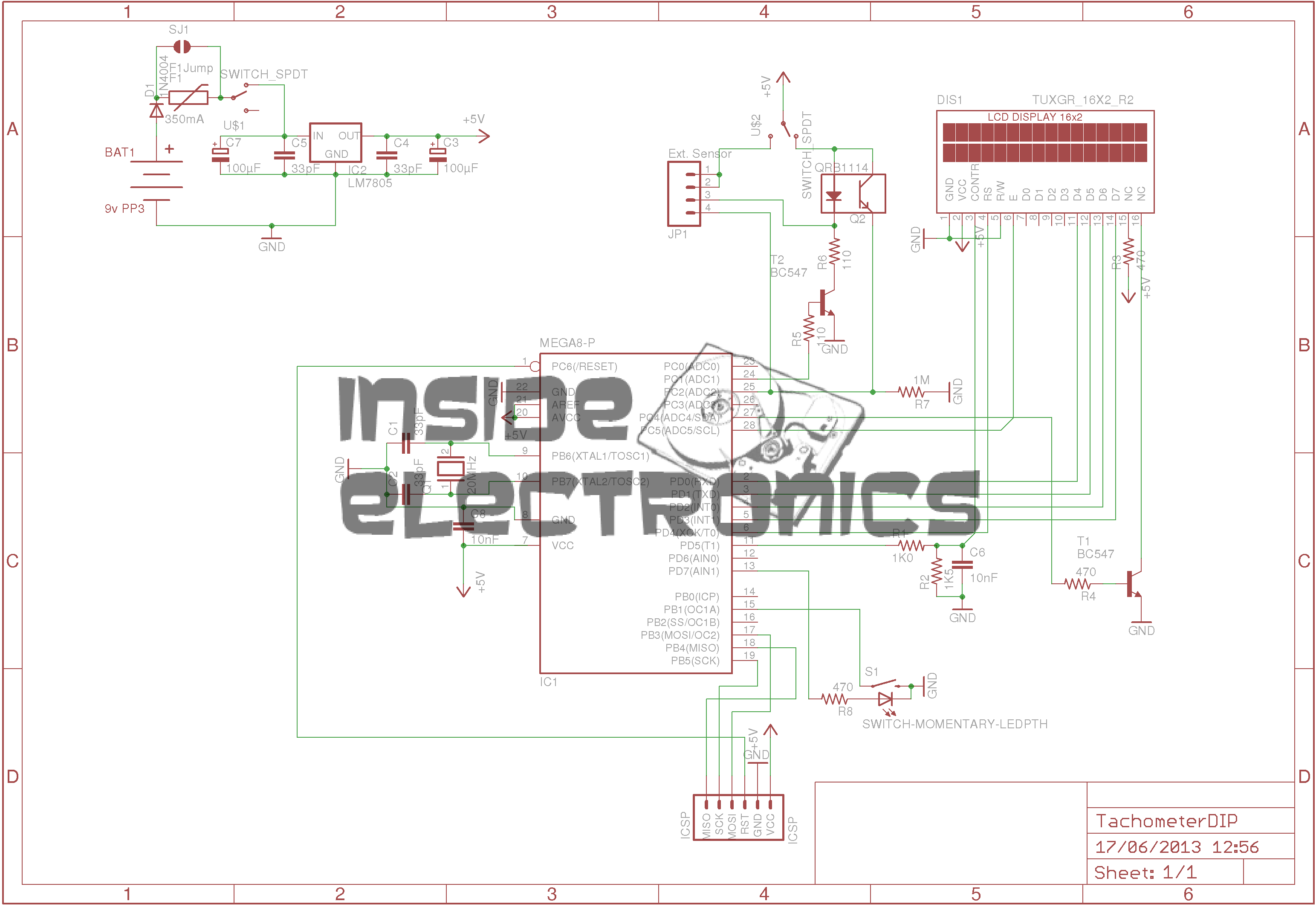
Here is an AVR powered optical tachometer design, that I adapted from the schematic found here.
I made a couple of changes to the circuit & designed a PCB & power supply module to be built in. The original design specified a surface mount IR LED/Photodiode pair, however my adjustment includes a larger IR reflectance sensor built onto the edge of the board, along with a Molex connector & a switch to select an externally mounted sensor instead of the onboard one.
There is also an onboard LM7805 based power supply, designed with a PCB mount PP3 battery box.
The power supply can also be protected by a 350mA polyfuse if desired. If this part isn’t fitted, then a pair of solder bridge pads are provided within the footprint for the fuse to short out the pads.
For more information on the basic design, please see the original post with the link at the top of the page.
Schematic
Here is an archive of the firmware & the Eagle CAD files for the PCB & schematic design.
Tip Jar
If you’ve found my content useful, please consider leaving a donation by clicking the Tip Jar below!
All collected funds go towards new content & the costs of keeping the server online.