As I mentioned in the previous post, these heaters have a standard interface that’s used for control & diagnostics, the W-Bus. This is transmitted over the K-Line of the vehicle bus, and all heaters, regardless of firmware modifications done by the various car manufacturers respond to this interface. Official Webasto diagnostic adaptors are available, but these are just a very expensive serial adaptor. A much cheaper option is a ~£5 Universal ODB adaptor.
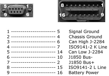
Above shows the signals on the ODB connector – the ones we’re interested in here are Pin 16, the +12v supply, and Pin 7, K-Line. Connect Pin 16 to the positive supply to the heater, and Pin 7 to Pin 2 on the Webasto heater. (Valid for all TT-V heaters).
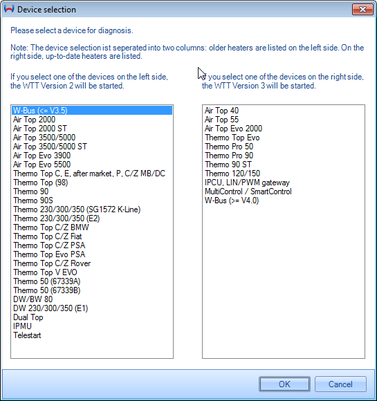
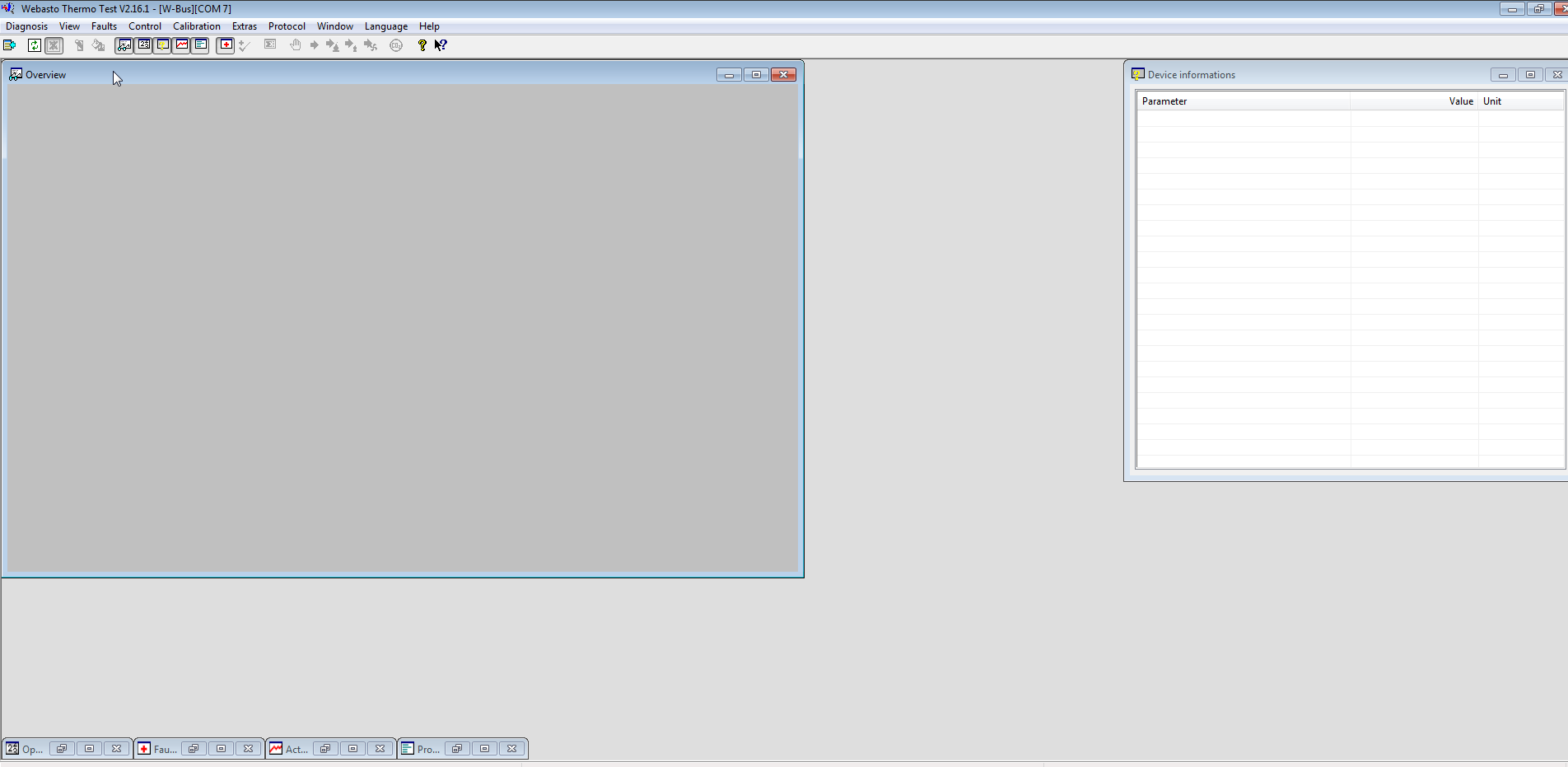
Once these two connections are made to the heater, fire up the Thermo Test software. The screen above will be displayed. Pick W-Bus at top left.
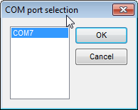
First thing, connect the ODB adaptor to USB, and change to the correct COM port in Thermo Test. There may be several in the list, but a newly connected USB device should show up with the highest COM number.
Once Thermo Test is running, start communications by going to the Diagnosis Menu > Start Diagnostic (F2 keyboard shortcut).
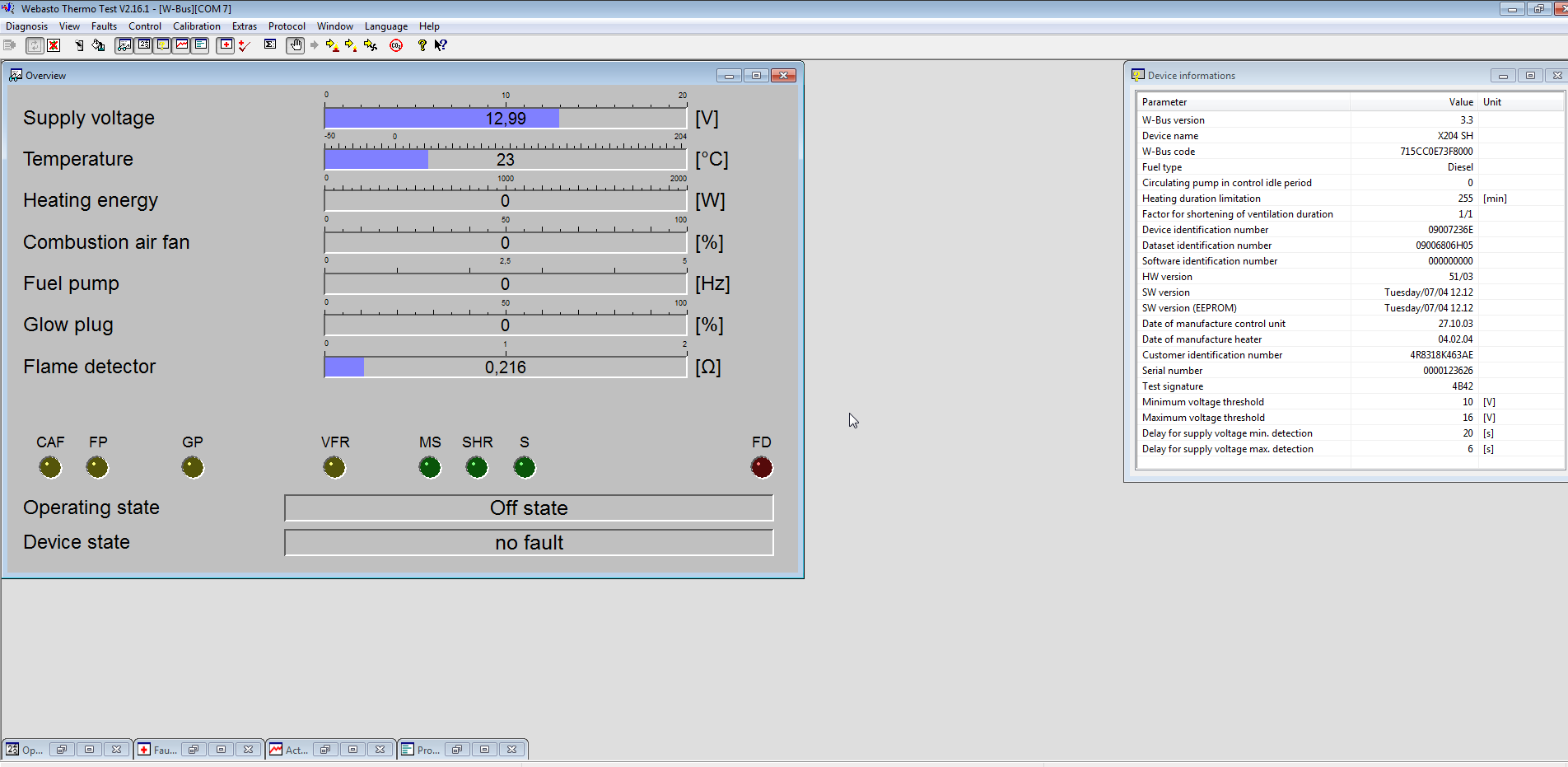
After a few seconds, communication will be established. This will show faults, if any are present, and allow testing of the heater & it’s component parts. A summary report can be generated with Diagnosis > View Summary:
Diagnosis report                                               Webasto Thermosystems
------------------------------------------------------------------------------------------


Configuration:
--------------
  W-Bus version...............................................................3.3
  Device name.............................................................X204 SH
  W-Bus code.......................................................715CC0E73F8000
  Fuel type................................................................Diesel
  Circulating pump in control idle period.......................................0
  Heating duration limitation.................................................255 [min]
  Factor for shortening of ventilation duration...............................1/1
  Device identification number..........................................09007236E
  Dataset identification number.......................................09006806H05
  Software identification number........................................000000000
  HW version................................................................51/03
  SW version..................................................Tuesday/07/04 12.12
  SW version (EEPROM).........................................Tuesday/07/04 12.12
  Date of manufacture control unit.......................................27.10.03
  Date of manufacture heater.............................................04.02.04
  Customer identification number.....................................4R8318K463AE
  Serial number........................................................0000123626
  Test signature.............................................................4B42
  Minimum voltage threshold....................................................10 [V]
  Maximum voltage threshold....................................................16 [V]
  Delay for supply voltage min. detection......................................20 [s]
  Delay for supply voltage max. detection.......................................6 [s]

Operating data:
---------------
  Working hours.............................................................44:03 [h:m]
  Operating hours.........................................................5388:08 [h:m]
  Start count...............................................................19129
  Burning duration PH 1..33%.................................................0:00 [h:m]
  Burning duration PH 34..66%................................................0:00 [h:m]
  Burning duration PH 67..100%...............................................0:00 [h:m]
  Burning duration PH >100%..................................................0:00 [h:m]
  Burning duration SH 1..33%.................................................0:00 [h:m]
  Burning duration SH 34..66%................................................0:00 [h:m]
  Burning duration SH 67..100%...............................................0:00 [h:m]
  Burning duration SH >100%..................................................0:00 [h:m]
  Working duration PH........................................................0:51 [h:m]
  Working duration SH......................................................121:10 [h:m]
  Start counter PH..............................................................6
  Start counter SH............................................................854
  Ventilation duration.......................................................0:00 [h:m]

Error:
------

------------------------------------------------------------------------------------------
12.03.17  17:17:30                                       Webasto Thermo Test  2.16.1
This shows all the important stuff, including running hours. (5388Hrs on this heater!). Most importantly, there are no faults listed.
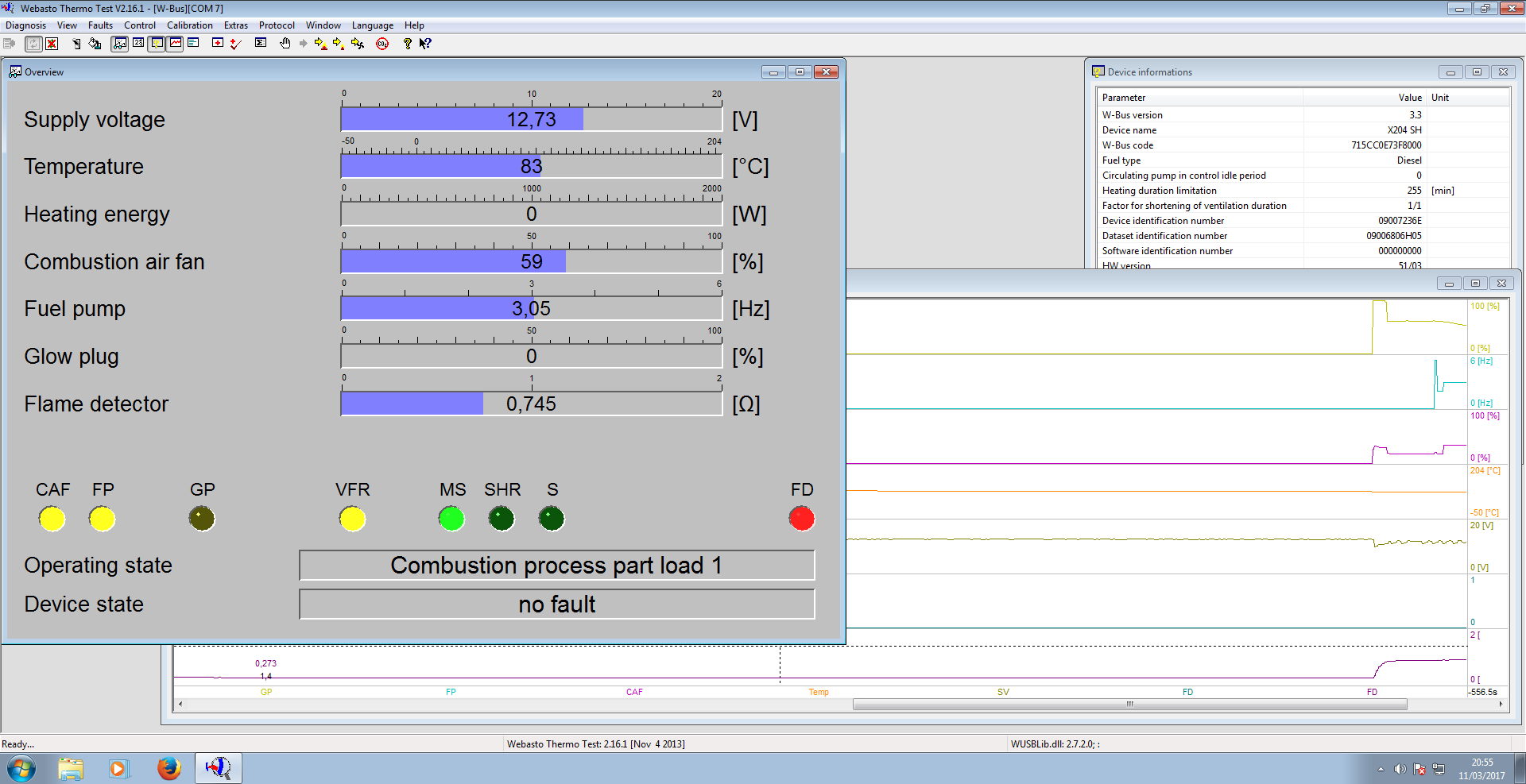
The heater can be fully tested by issuing a start command from the Command Menu > Parking Heating option. Obviously cooling water will be required for this, along with an external water pump. (The water pump control output on these heaters seems to be totally disabled in firmware, as they rely on the engine’s coolant pump). I used a bucket of water along with a small centrifugal pump to provide the cooling. During this test I noted that the firmware is much more aggressive in these units. The marine versions shut down at ~72°C water temperature, whereas these don’t so the same until ~90°C.
Now I’ve managed to communicate with the heater, I’ll get onto building a standalone controller so I can dispense with the Windows VM for control.