I wrote a few weeks ago about replacing the hot water circulating pump on the boat with a new one, and mentioned that we’d been through several pumps over the years. After every replacement, autopsy of the pump has revealed the failure mode: the first pump failed due to old age & limited life of carbon brushes. The second failed due to thermal shock from an airlock in the system causing the boiler to go a bit nuts through lack of water flow. The ceramic rotor in this one just cracked.
The last pump though, was mechanically worn, the pump bearings nicely polished down just enough to cause the rotor to stick. This is caused by sediment in the system, which comes from corrosion in the various components of the system. Radiators & skin tanks are steel, engine block cast iron, back boiler stainless steel, Webasto heat exchanger aluminium, along with various bits of copper pipe & hose tying the system together.
The use of dissimilar metals in a system is not particularly advisable, but in the case of the boat, it’s unavoidable. The antifreeze in the water does have anti-corrosive additives, but we were still left with the problem of all the various oxides of iron floating around the system acting like an abrasive. To solve this problem without having to go to the trouble of doing a full system flush, we fitted a magnetic filter:
Mag Filter
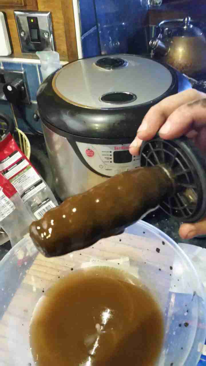
This is just an empty container, with a powerful NdFeB magnet inserted into the centre. As the water flows in a spiral around the magnetic core, aided by the offset pipe connections, the magnet pulls all the magnetic oxides out of the water. it’s fitted into the circuit at the last radiator, where it’s accessible for the mandatory maintenance.
Sludge
Now the filter has been in about a month, I decided it would be a good time to see how much muck had been pulled out of the circuit. I was rather surprised to see a 1/2″ thick layer of sludge coating the magnetic core! The disgusting water in the bowl below was what drained out of the filter before the top was pulled. (The general colour of the water in the circuit isn’t this colour, I knocked some loose from the core of the filter while isolating it).
If all goes well, the level of sludge in the system will over time be reduced to a very low level, with the corrosion inhibitor helping things along. This should result in much fewer expensive pump replacements!
As I’ve been posting some photos of decapped ICs lately, I thought I’d share the process I use personally for those that might want to give it a go 😉
The usual method for removing the epoxy package from the silicon is to use hot, concentrated Nitric Acid. Besides the obvious risks of having hot acids around, the decomposition products of the acid, namely NO² (Nitrogen Dioxide) & NO (Nitrogen Oxide), are toxic and corrosive. So until I can get the required fume hood together to make sure I’m not going to corrode the place away, I’ll leave this process to proper labs ;).
The method I use is heat based, using a Propane torch to destroy the epoxy package, without damaging the Silicon die too much.
TMS57002 Audio DSP
I start off, obviously, with a desoldered IC, the one above an old audio DSP from TI. I usually desolder en-masse for this with a heat gun, stripping the entire board in one go.
FLAMES!
Next is to apply the torch to the IC. A bit of practice is required here to get the heat level & time exactly right, overheating will cause the die to oxidize & blacken or residual epoxy to stick to the surface.
I usually apply the torch until the package just about stops emitting it’s own yellow flames, meaning the epoxy is almost completely burned away. I also keep the torch flame away from the centre of the IC, where the die is located.
Breathing the fumes from this process isn’t recommended, no doubt besides the obvious soot, the burning plastic will be emitting many compounds not brilliant for Human health!
Once the IC is roasted to taste, it’s quenched in cold water for a few seconds. Sometimes this causes such a high thermal shock that the leadframe cracks off the epoxy around the die perfectly.
All Your Die Belong To Us
Now that the epoxy has been destroyed, it breaks apart easily, and is picked away until I uncover the die itself. (It’s the silver bit in the middle of the left half). The heat from the torch usually destroys the Silver epoxy holding the die to the leadframe, and can be removed easily from the remaining package.
Decapped
BGA packages are usually the easiest to decap, flip-chip packages are a total pain due to the solder balls being on the front side of the die, I haven’t managed to get a good result here yet, I’ll probably need to chemically remove the first layer of the die to get at the interesting bits 😉
Slide
Once the die has been rinsed in clean water & inspected, it’s mounted on a glass microscope slide with a small spot of Cyanoacrylate glue to make handling easier.
Some dies require some cleaning after decapping, for this I use 99% Isopropanol & 99% Acetone, on the end of a cotton bud. Any residual epoxy flakes or oxide stuck to the die can be relatively easily removed with a fingernail – turns out fingernails are hard enough to remove the contamination, but not hard enough to damage the die features.
Once cleaning is complete, the slide is marked with the die identification, and the photographing can begin.
Microscope Mods
I had bought a cheap eBay USB microscope to get started, as I can’t currently afford a proper metallurgical microscope, but I found the resolution of 640×480 very poor. Some modification was required!
Modified Microscope
I’ve removed the original sensor board from the back of the optics assembly & attached a Raspberry Pi camera board. The ring that held the original sensor board has been cut down to a minimum, as the Pi camera PCB is slightly too big to fit inside.
The stock ring of LEDs is run direct from the 3.3v power rail on the camera, through a 4.7Ω resistor, for ~80mA. I also added a 1000µF capacitor across the 3.3v supply to compensate a bit for the long cable – when a frame is captured the power draw of the camera increases & causes a bit of voltage drop.
The stock lens was removed from the Pi camera module by careful use of a razor blade – being too rough here *WILL* damage the sensor die or the gold bond wires, which are very close to the edge of the lens housing, so be gentle!
Mounting Base
The existing mount for the microscope is pretty poor, so I’ve used a couple of surplus ceramic ring magnets as a better base, this also gives me the option of raising or lowering the base by adding or removing magnets.
To get more length between the Pi & the camera, I bought a 1-meter cable extension kit from Pi-Cables over at eBay, cables this long *definitely* require shielding in my space, which is a pretty aggressive RF environment, or interference appears on the display. Not surprising considering the high data rates the cable carries.
The FFC interface is hot-glued to the back of the microscope mount for stability, for handheld use the FFC is pretty flexible & doesn’t apply any force to the scope.
Die Photography
Since I modified the scope with a Raspberry Pi camera module, everything is done through the Pi itself, and the raspistill command.
Pi LCD
The command I’m currently using to capture the images is:
raspistill -ex auto -awb auto -mm matrix -br 62 -q 100 -vf -hf -f -t 0 -k -v -o CHIPNAME_%03d.jpg
This command waits between each frame for the ENTER key to be pressed, allowing me to position the scope between shots. Pi control & file transfer is done via SSH, while I use the 7″ touch LCD as a viewfinder.
The direct overhead illumination provided by the stock ring of LEDs isn’t ideal for some die shots, so I’m planning on fitting some off-centre LEDs to improve the resulting images.
Image Processing
Obviously I can’t get an ultra-high resolution image with a single shot, due to the focal length, so I have to take many shots (30-180 per die), and stitch them together into a single image.
For this I use Hugin, an open-source panorama photo stitching package.
Hugin
Here’s Hugin with the photos loaded in from the Raspberry Pi. To start with I use Hugin’s built in CPFind to process the images for control points. The trick with getting good control points is making sure the images have a high level of overlap, between 50-80%, this way the software doesn’t get confused & stick the images together incorrectly.
Optimiser
After the control points are generated, which for a large number of high resolution images can take some time, I run the optimiser with only Yaw & Pitch selected for all images.
Optimising
If all goes well, the resulting optimisation will get the distance between control points to less than 0.3 pixels.
Panorama Preview
After the control points & optimisation is done, the resulting image can be previewed before generation.
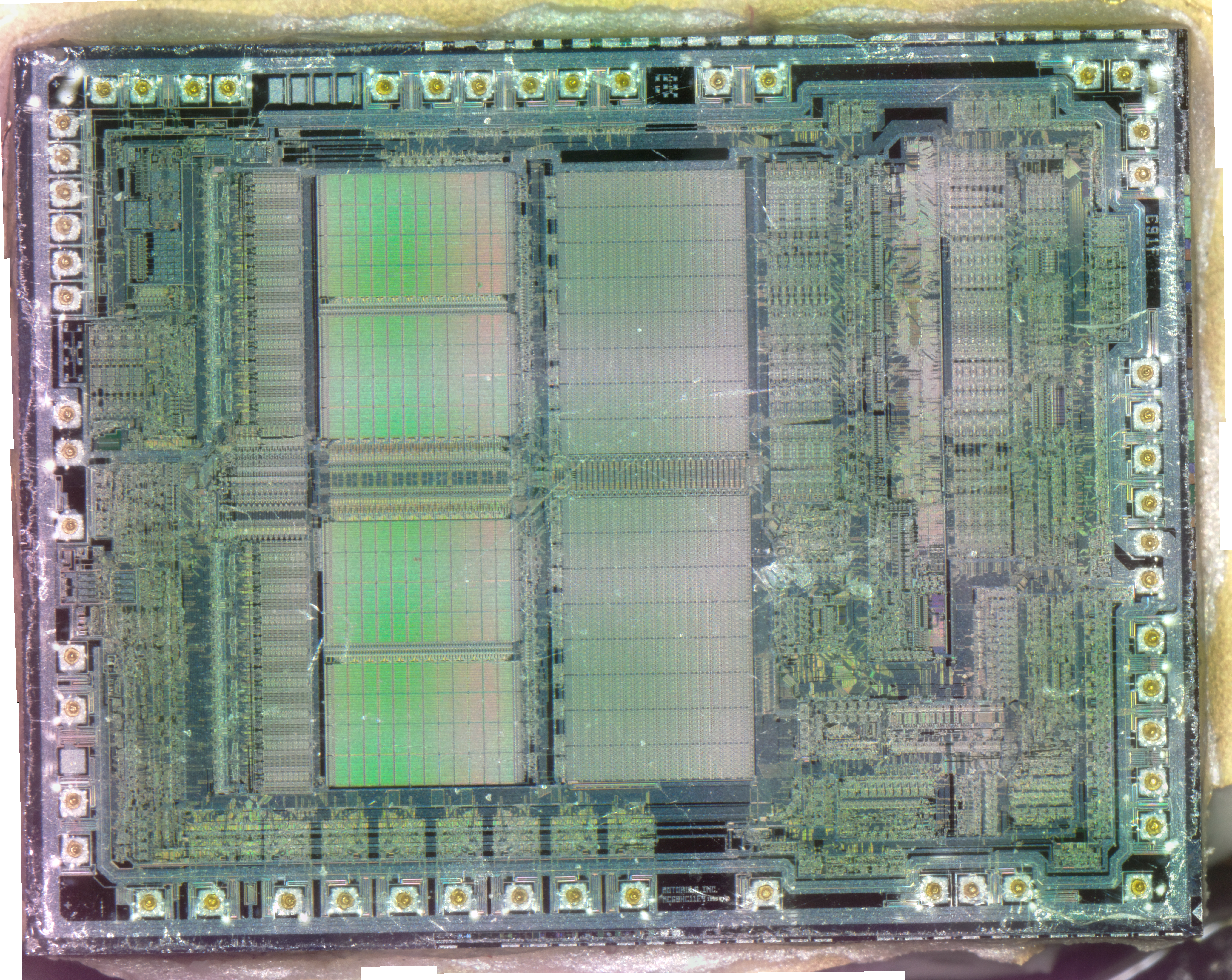
Texas Instruments TMS67002
After all the image processing, the resulting die image should look something like the above, with no noticeable gaps.
This particular IC came out of a very old VHF band radio, from the early 90’s. The die was encased in a custom ceramic package, like every other IC in the radio, with a custom part number. I managed to identify it from the markings on the silicon.
Motorola MC68HC11L6
This was a pretty powerful MCU for it’s time, with 16K of onboard ROM, 512 bytes of both RAM & EEPROM, a 16-bit timer, 8-bit ADC, SPI & a MC68HC11 CPU core.
Everyone at some stage must have seen these EAS security tags in shops, usually attached to clothing with a steel pin. As some of this year’s presents had been left with the tags attached, I had to forcibly remove them before wrapping could commence.
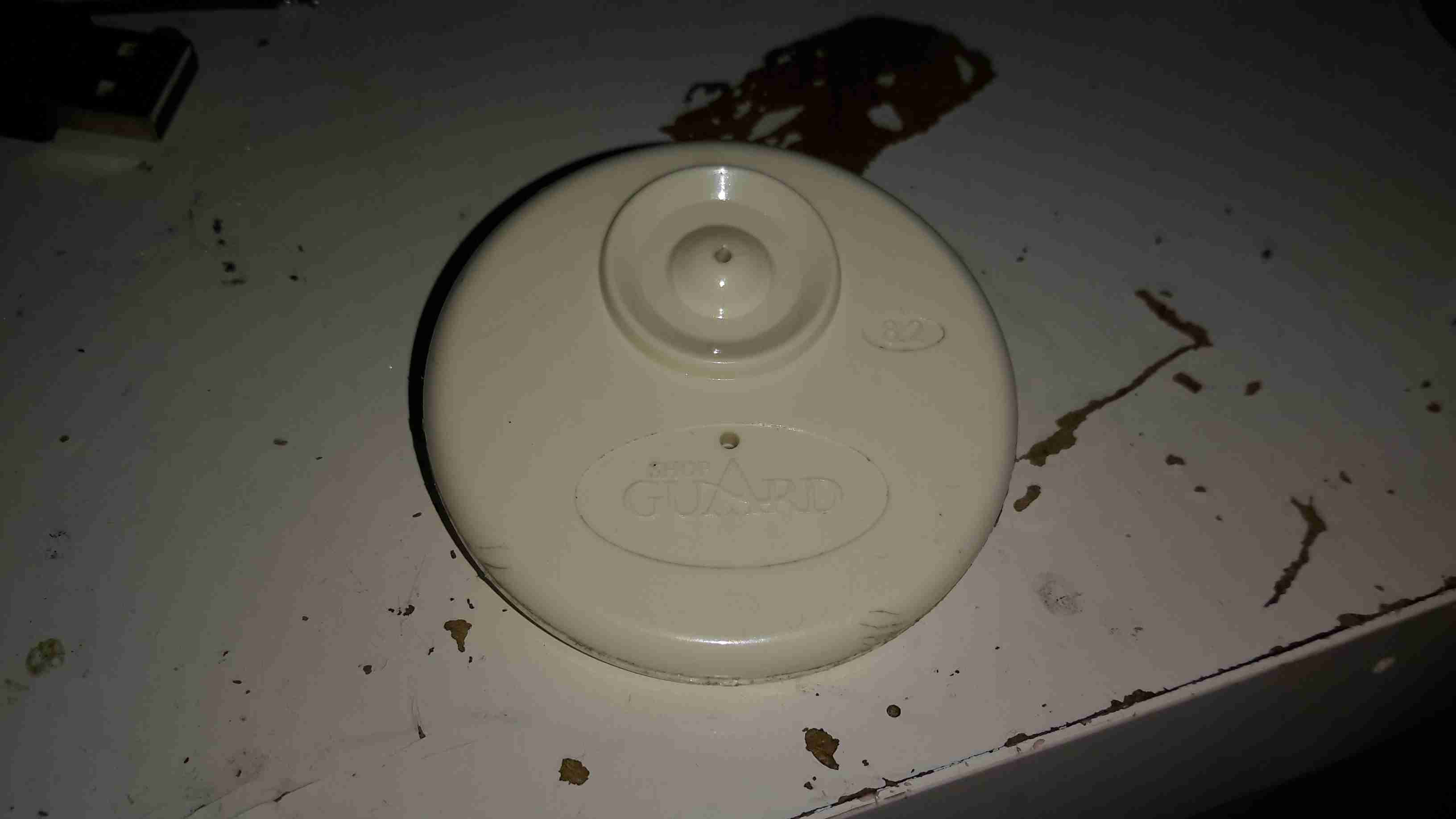
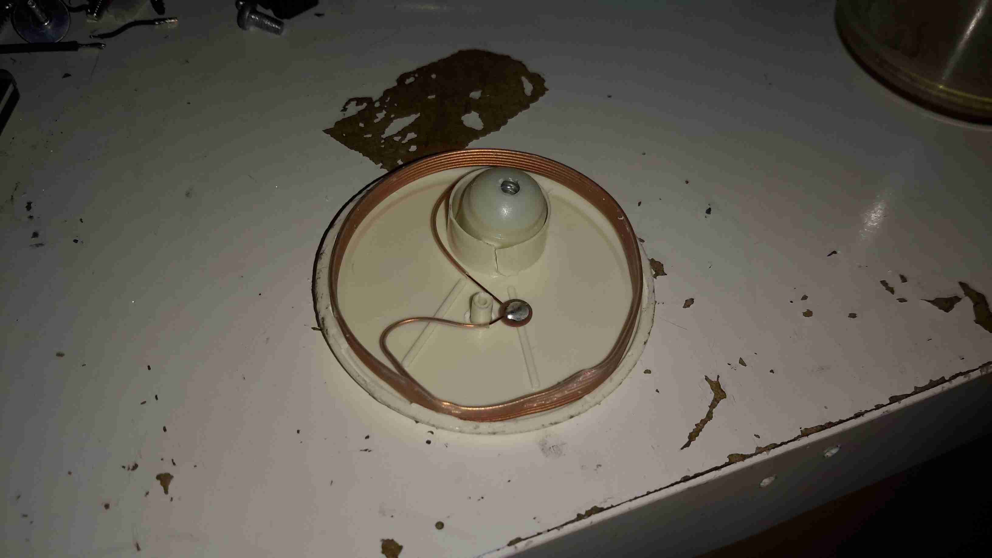
Reverse Side
These are just a plastic disc about 50mm in diameter, with an internal locking mechanism & RF tag inside.
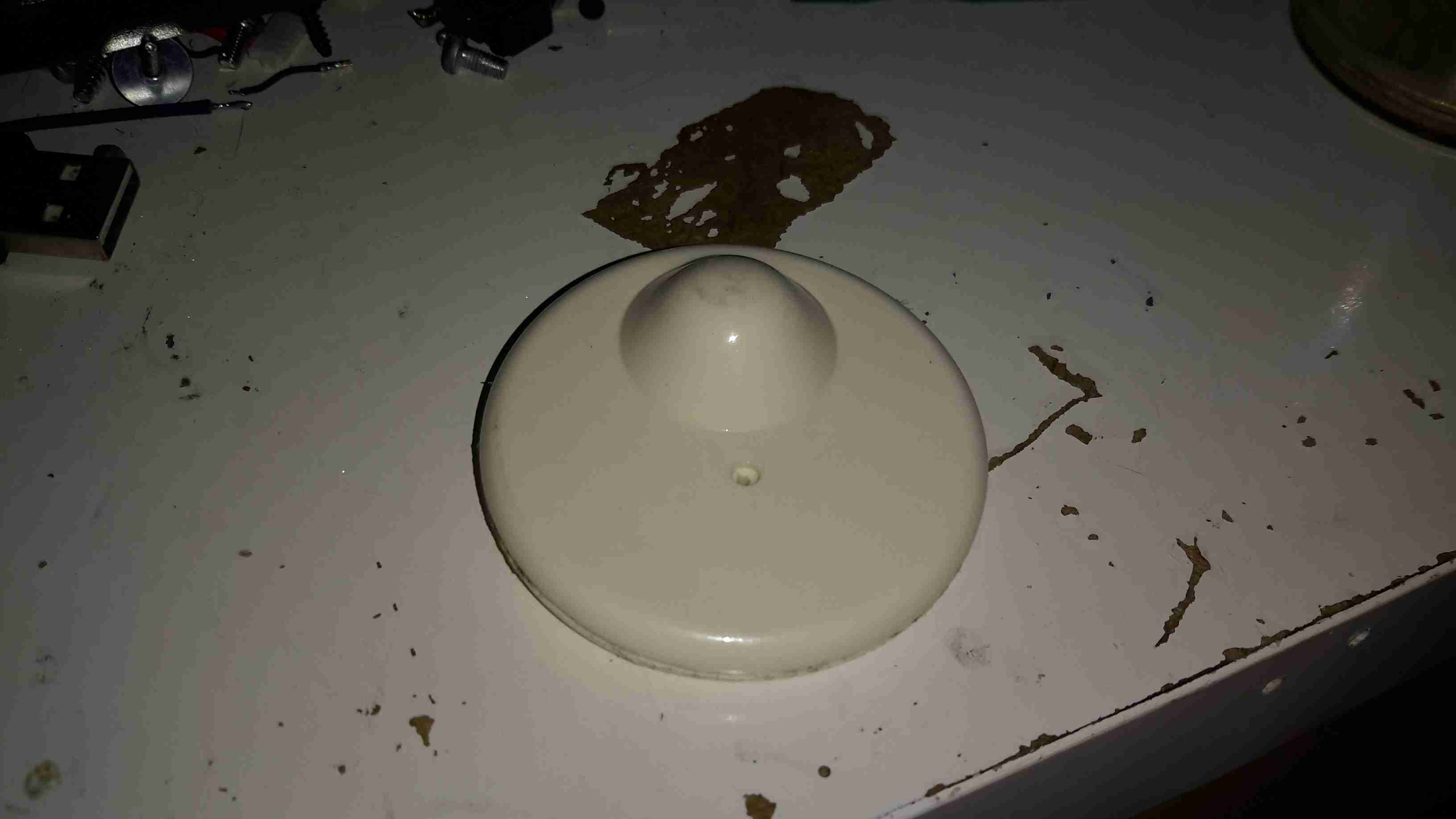
RF Coil
After some careful attack with a saw around the glue seam, the tag comes apart into it’s halves. The RF coil & it’s ceramic capacitor can be seen wrapped around the outside of the tag. The capacitor in this case isn’t even epoxy dipped to save that extra 0.0001p on the manufacturing price. In the top centre is the pin locking mechanism, enclosed in a small plastic pill.
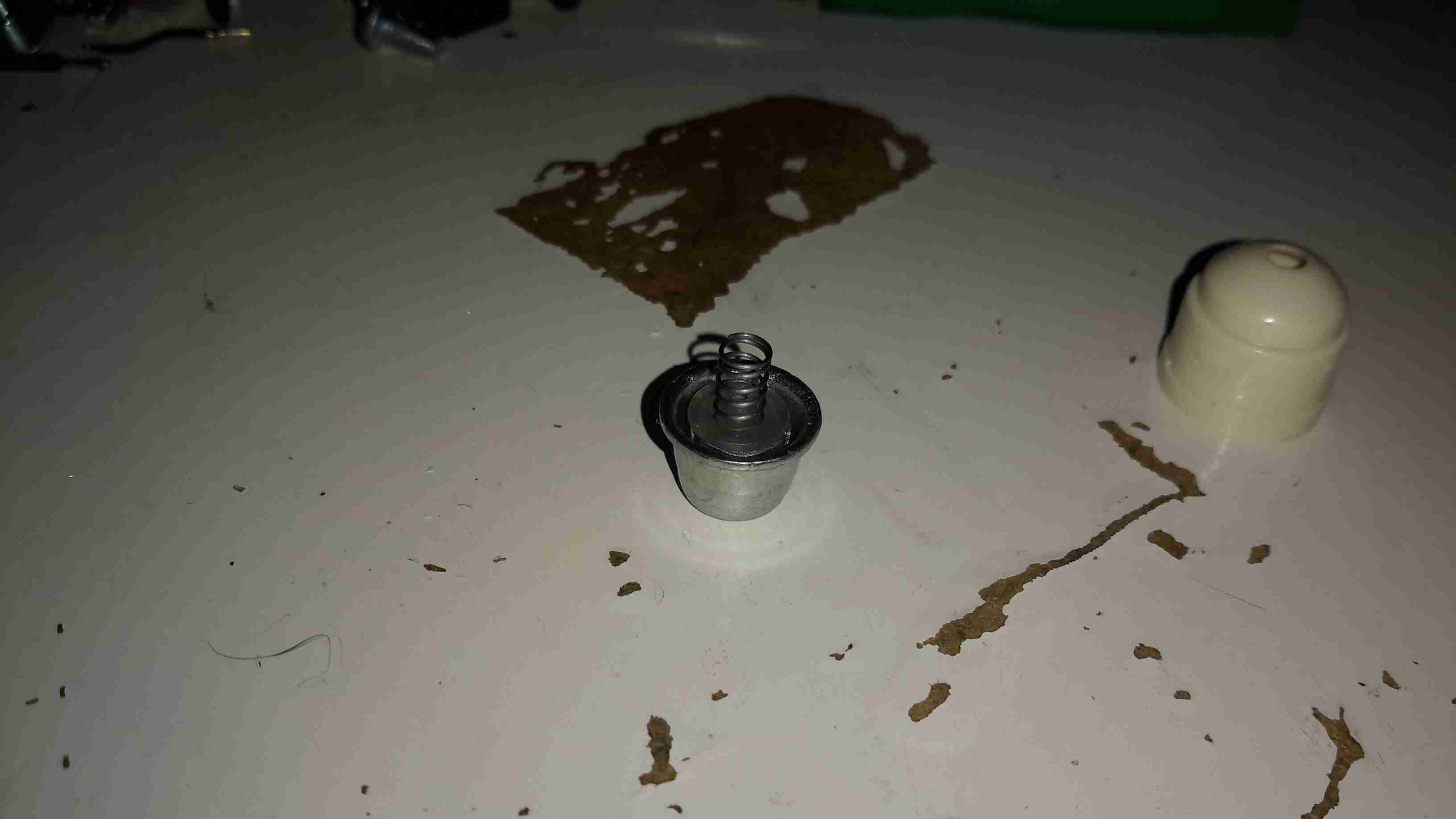
Lock Pill
Popping off the back cap of the lock shows it’s internals.
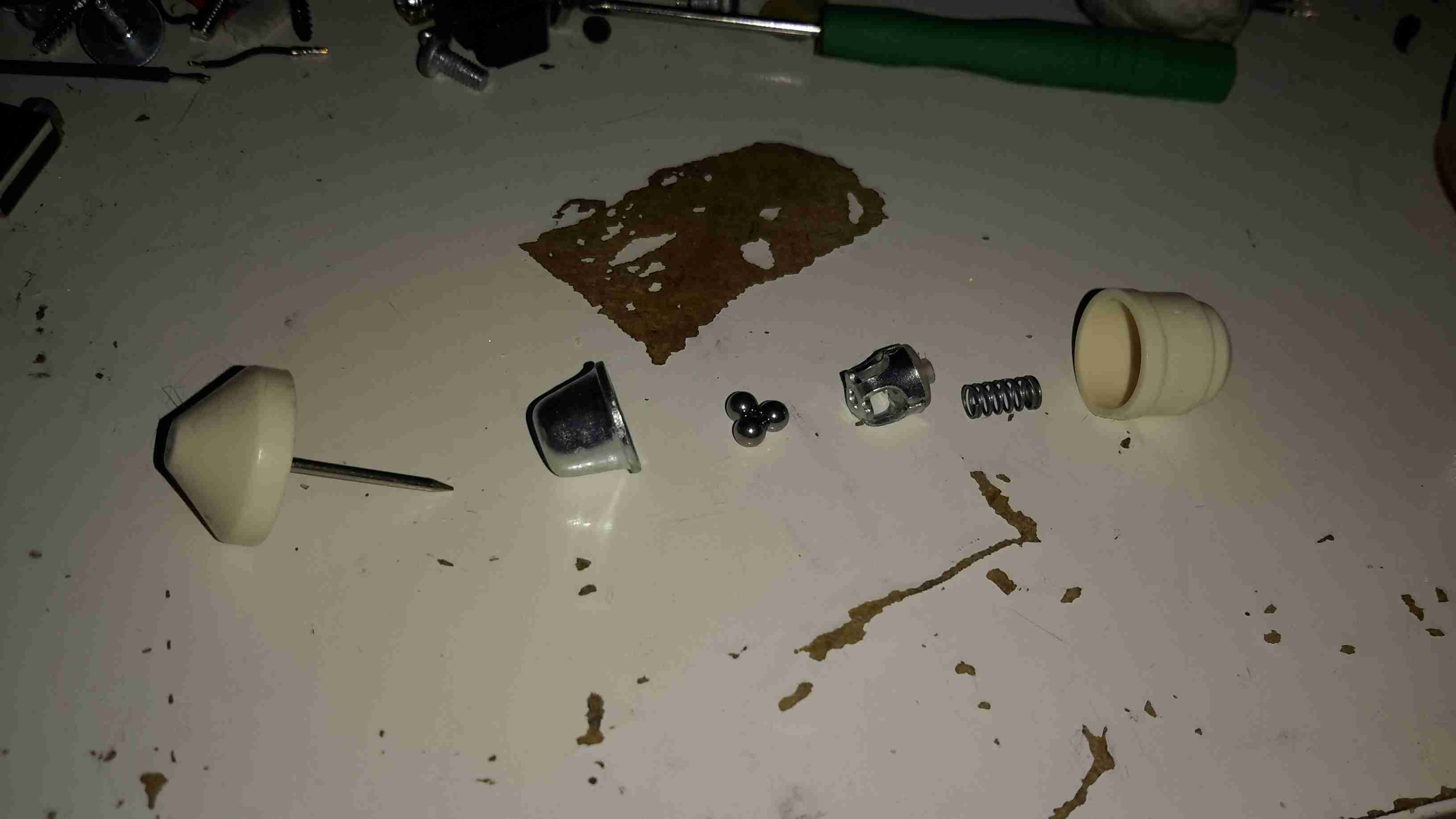
Ball Bearing Lock Assembly
The lock itself is very simple. The centre section, held in place by a spring, carries 3 small ball bearings. The outer metal frame of the lock is conical in shape.
When the pin is pushed into the tag, the conical shape of the lock chamber causes the ball bearings to grab onto it, helped by the action of the spring that pushes the ball bearing carrier further into the cone.
This also means that any attempt to force the mechanism causes it to lock tighter onto the pin.
In normal operation, removal is achieved by a strong magnet that pulls the ball bearing carrier back slightly against it’s spring, allowing the pin to disengage & be pulled out.
This design is incredibly simple & cheap to make, and gains it’s locking strength from friction alone.
I would consider the RF coil being around the outer edge of the device a bit of a security risk – a quick chop with a sharp pair of wire cutters would disable the tag’s alarm functionality instantly. Making the coil slightly smaller & keeping it out of reach of the edge of the tag would help in this regard.
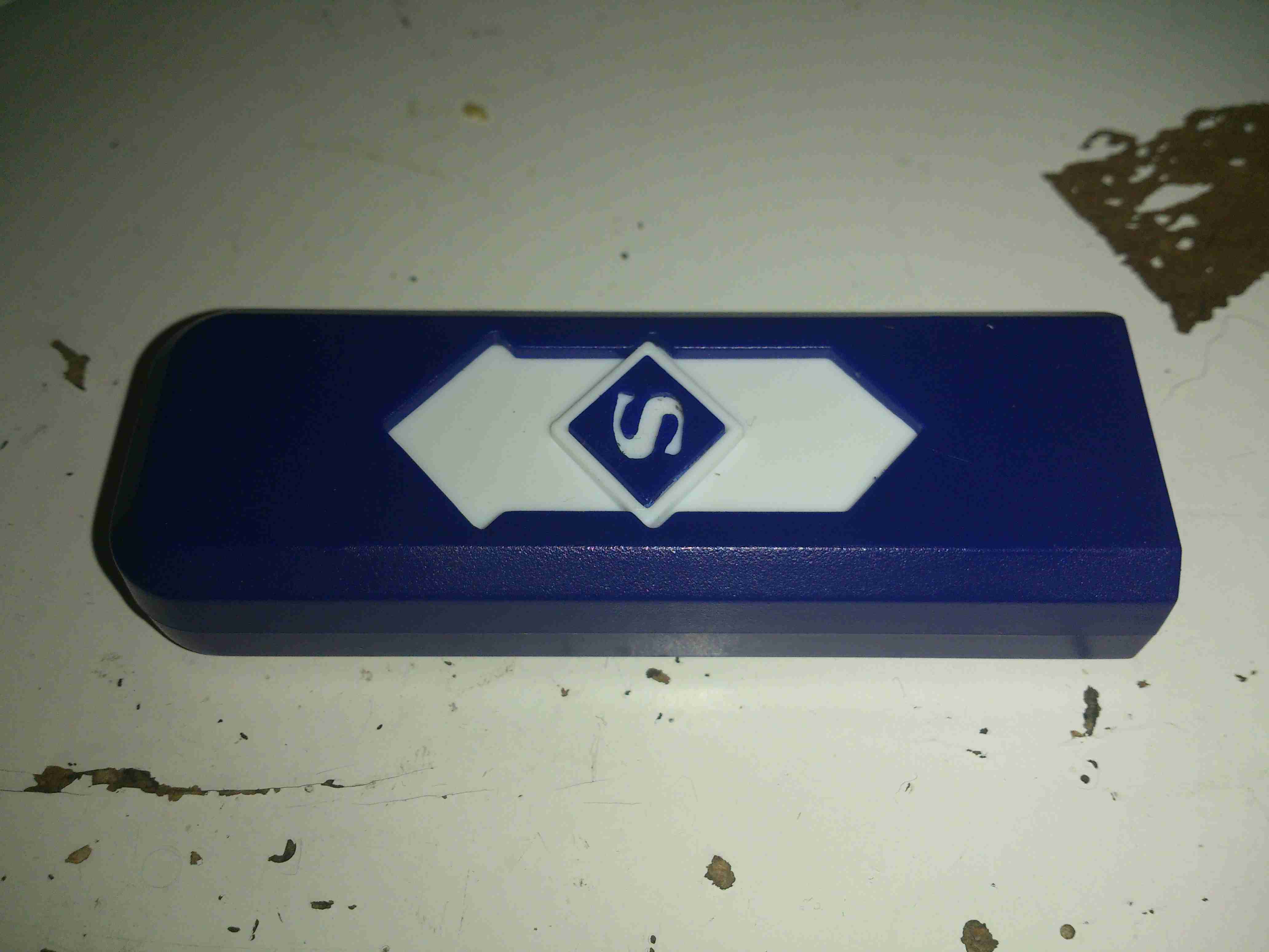
With a recent order from a Chinese seller on eBay, this little gadget was included in the package as a freebie:
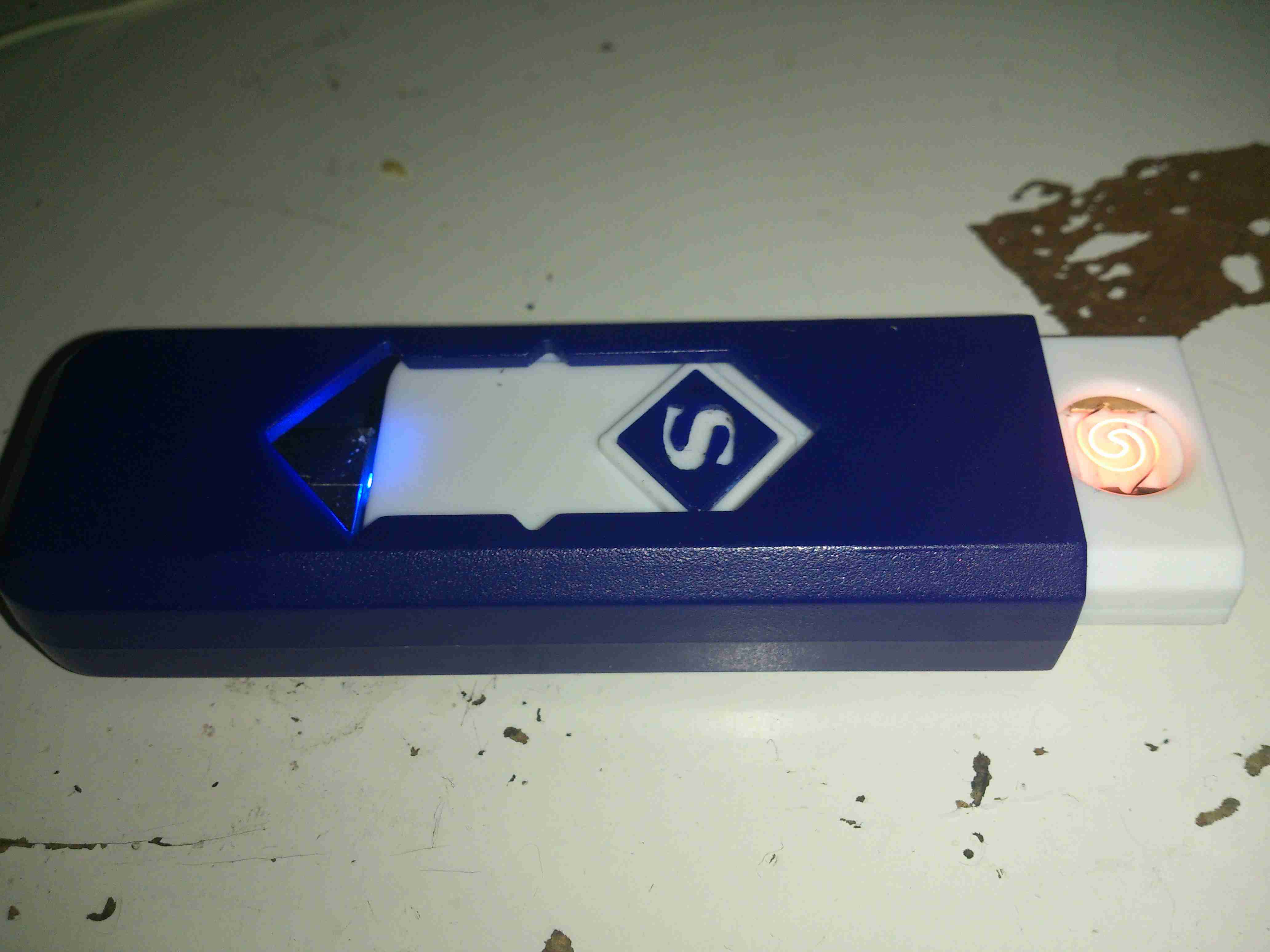
Electronic Lighter
I’ve not smoked for a long time, so I’m not too sure what use I’m going to find for this device, but it’s an electronic lighter!
Pyromaniac Mode
Pushing the slider forward reveals a red-hot heater, mounted in the plastic (!) frame.
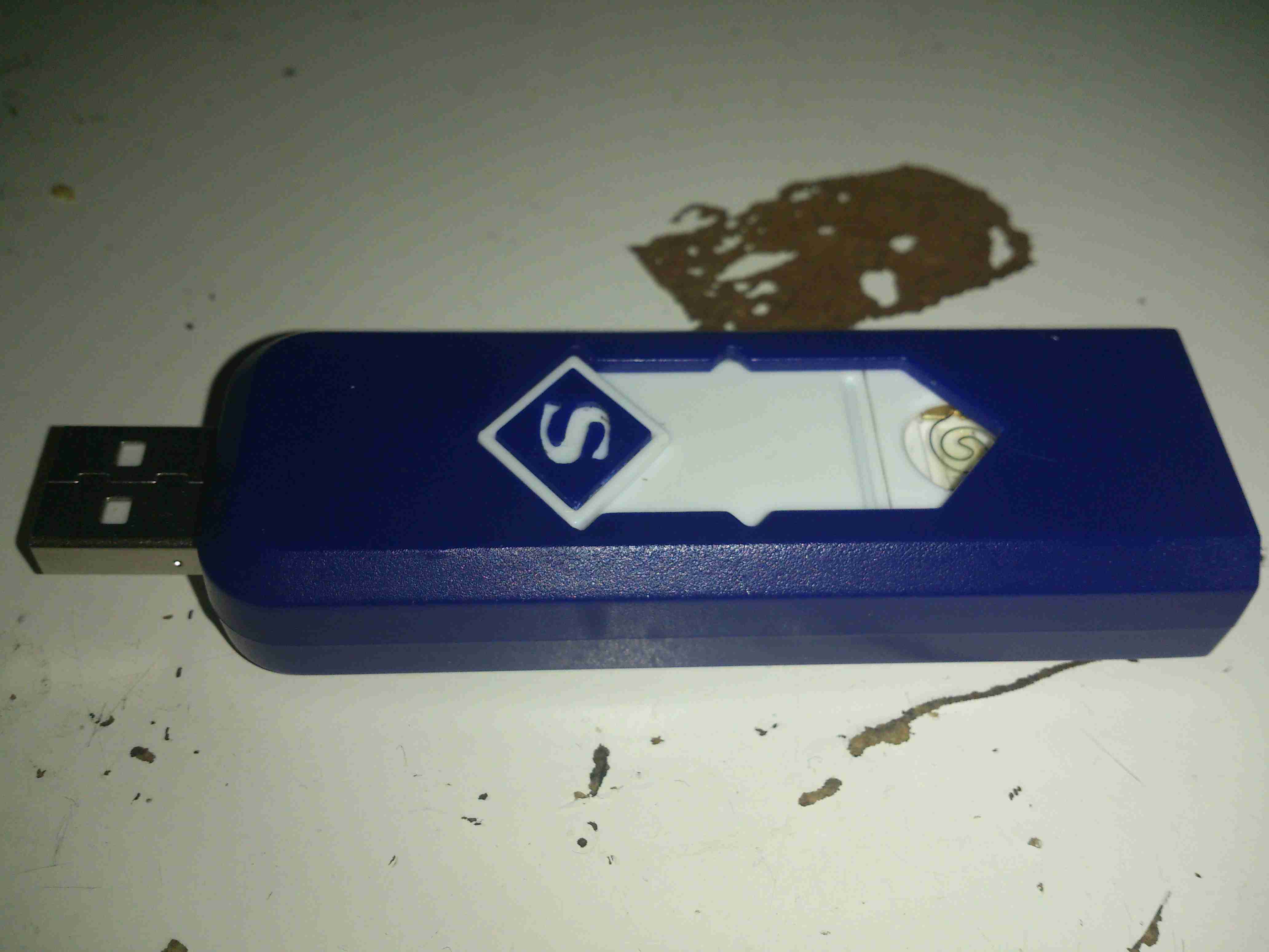
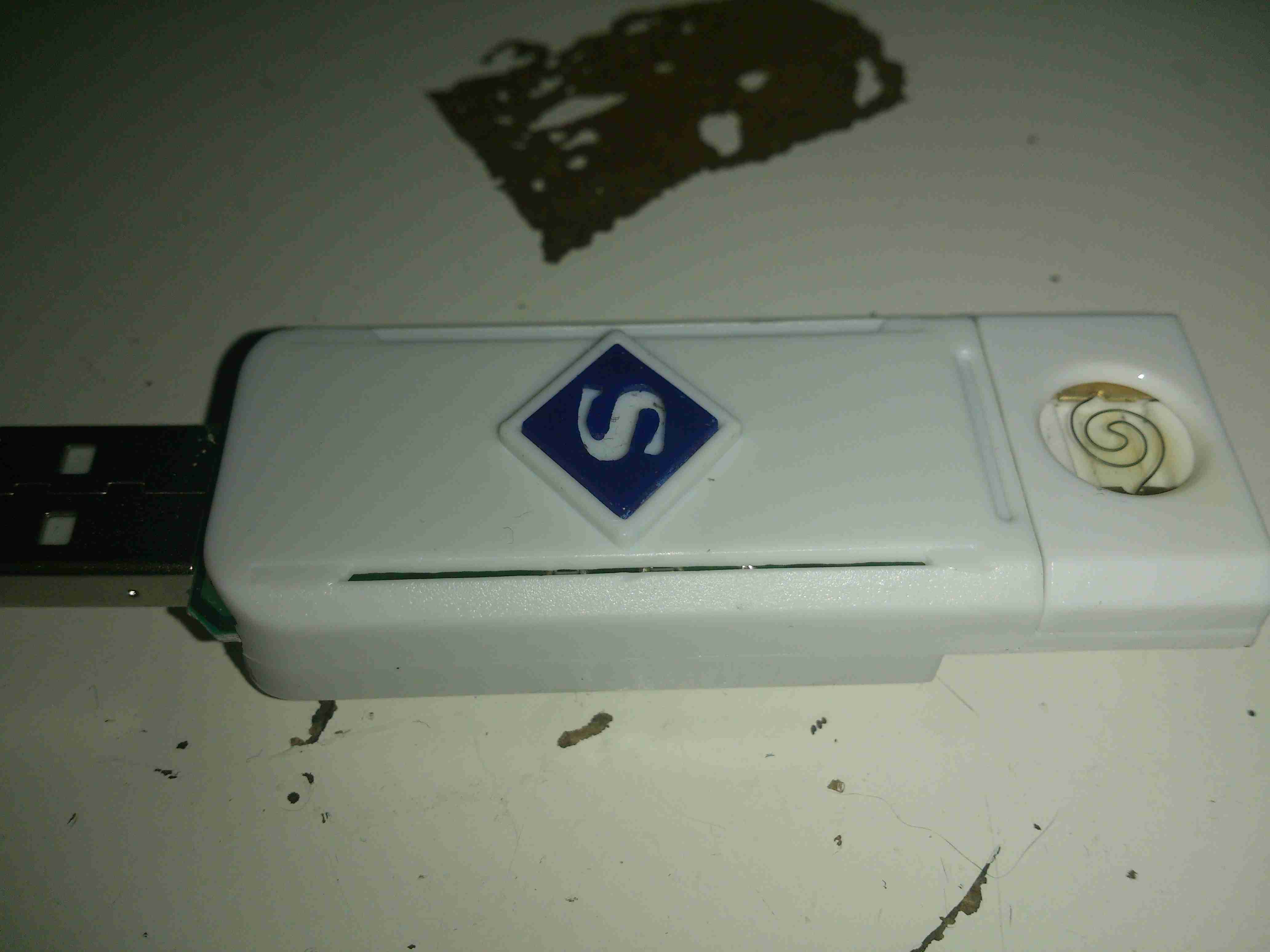
Charging Mode
Pushing the other way reveals a USB port to charge the internal battery.
Core Removed
A couple of screws releases the end cap from the cover & the entire core unit slides out. Like all Chinese toys it’s made of the cheapest plastic imaginable, not such a good thing when heat is involved.
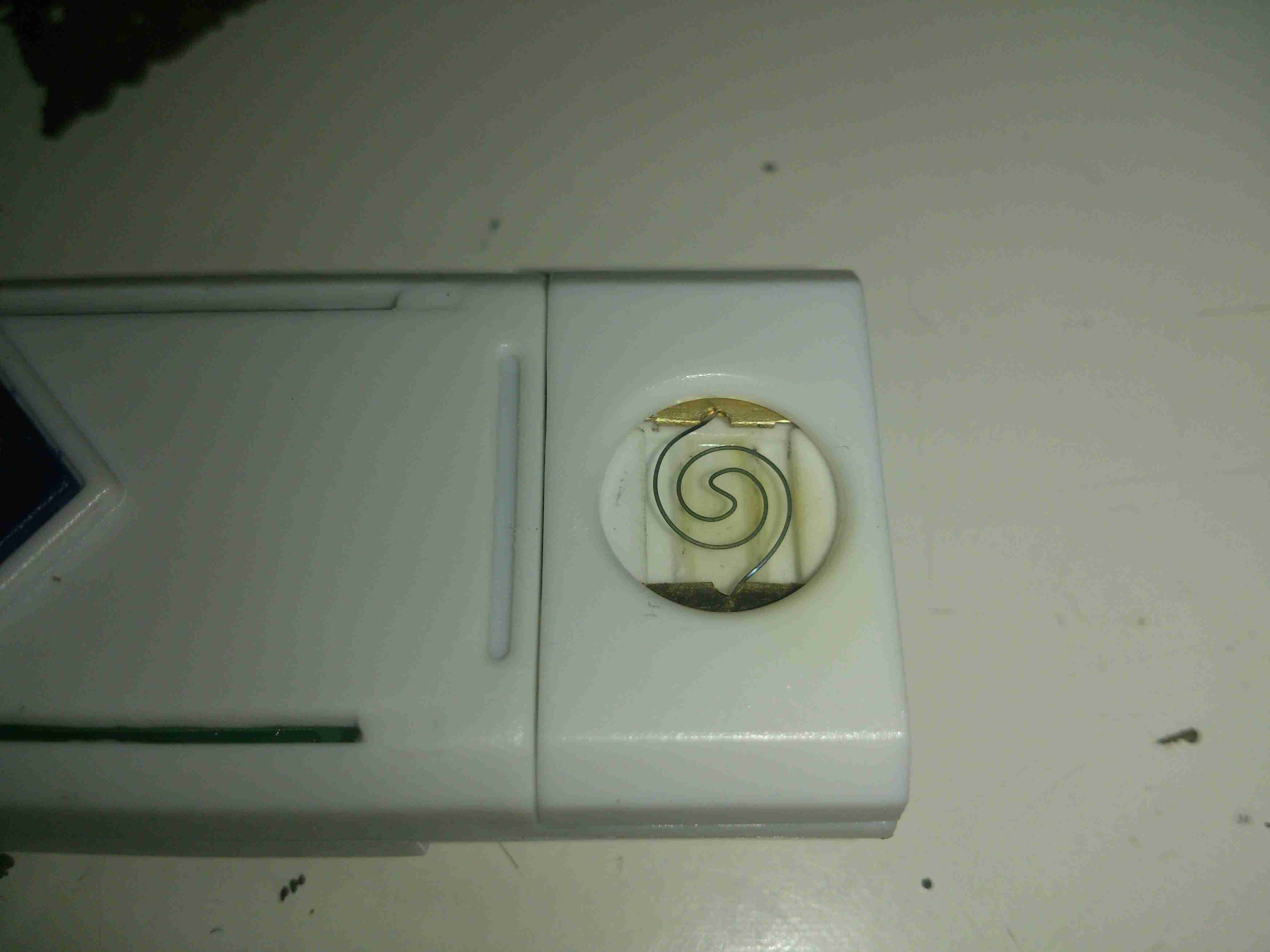
Heating Element
The element itself is a simple coil of Nichrome wire, crimped to a pair of brass terminals. The base the heater & it’s terminals are mounted to is actually ceramic – the surround though that this ceramic pill clips into is just the same cheap plastic. Luckily, the element only remains on for a few seconds on each button push, there’s no way to keep it on & start an in-pocket fire, as far as I can see.
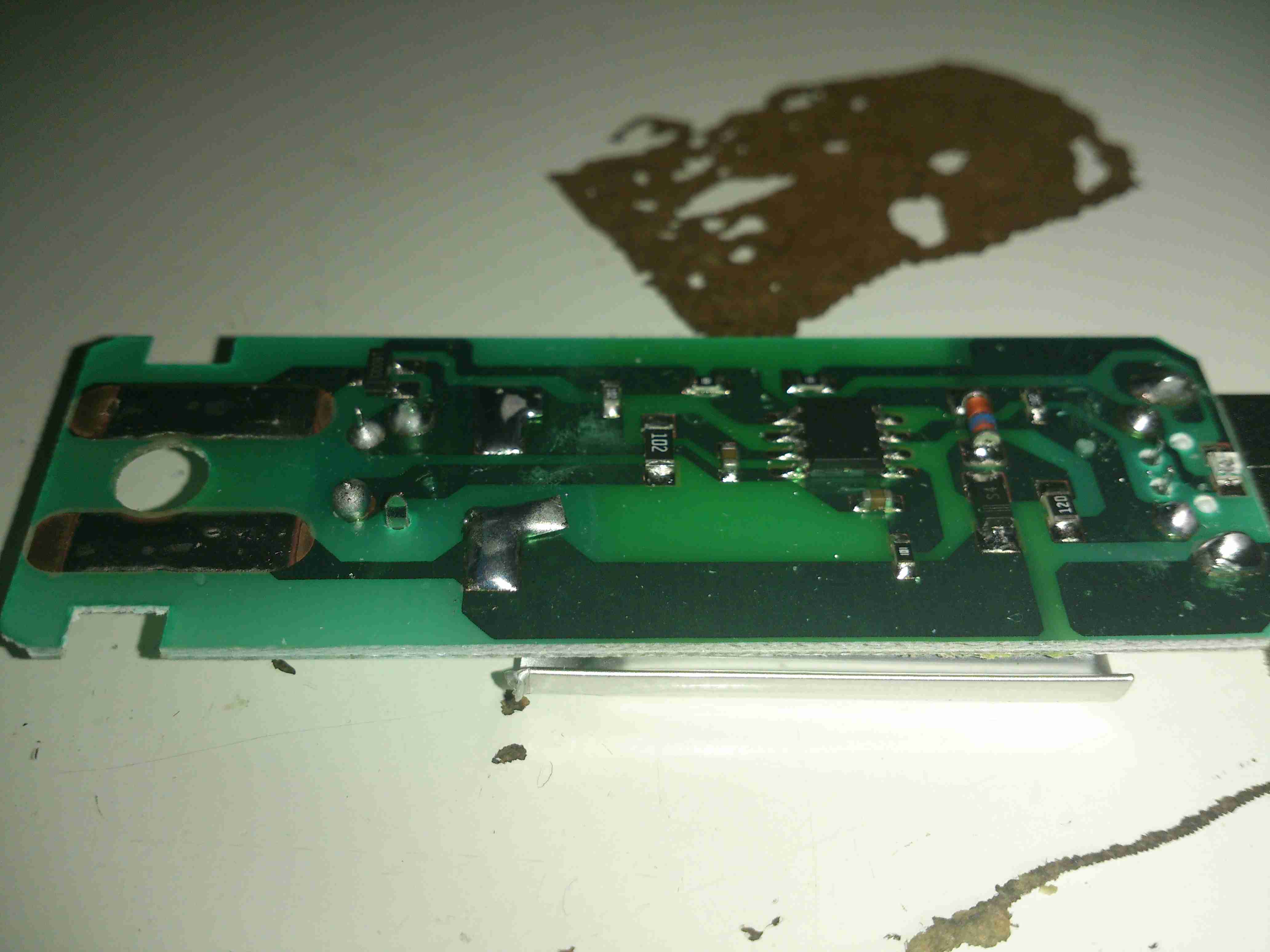
Main PCB
The main PCB clips out of the back of the core frame, the large pair of tinned pads on the left connect to the heater, the control IC has no numbering of any kind, but considering the behaviour of the device it’s most likely a standard eCig control IC.
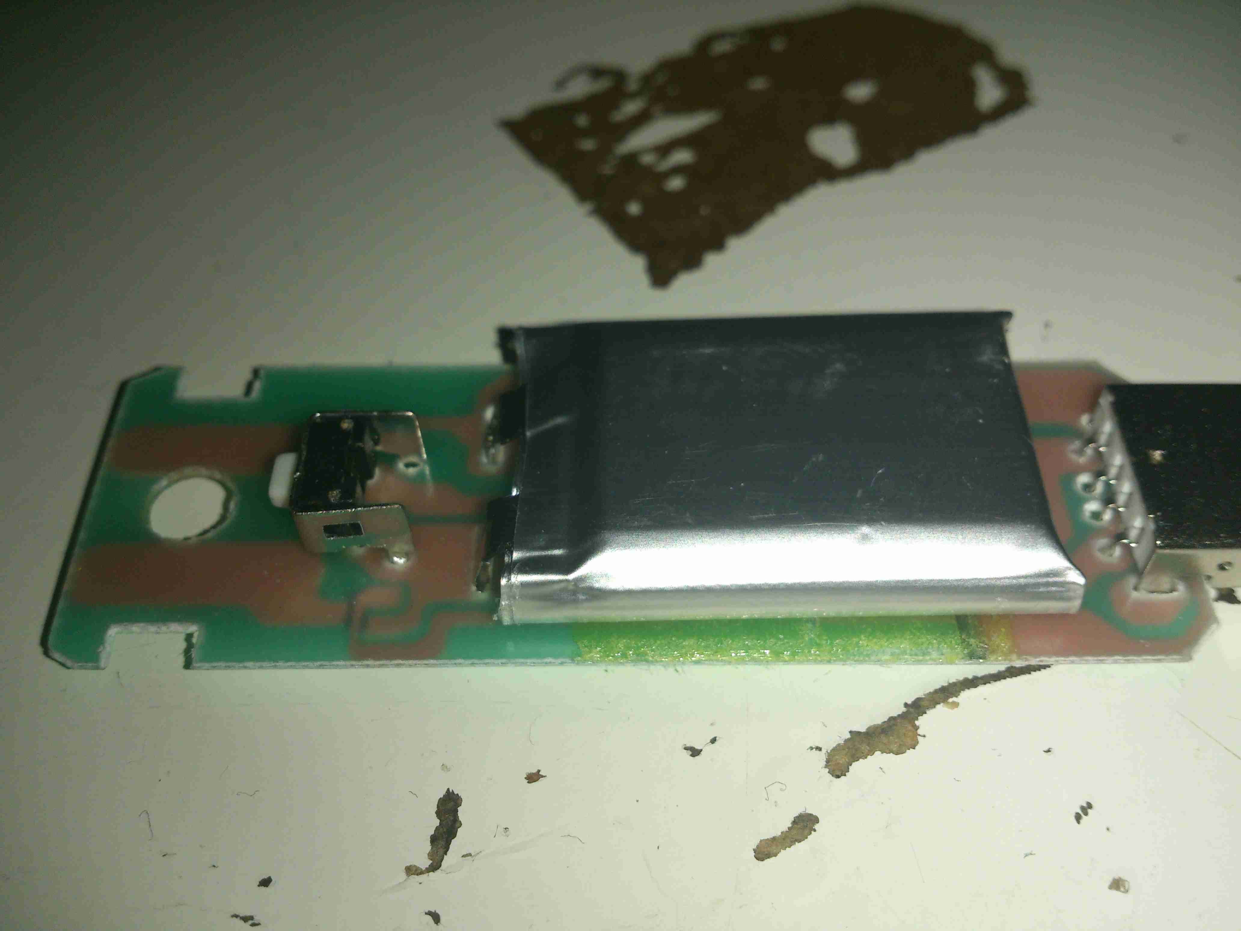
LiPo Cell
The other side of the board has the USB port on the right, the Lithium Polymer cell in the centre, and the power button on the left. The cell itself also has no marking, but I’m guessing a couple hundred mAh from the physical size.
Recently I’ve noticed my usual mobile rig, the Baofeng UV-5R, has had very poor receive, and non-existent transmit.
I did a power test on the radio, and confirmed it was still outputting it’s rated RF power. Trying another antenna proved that the radio was fine.
Time to tear down the antenna & see if it can be fixed!
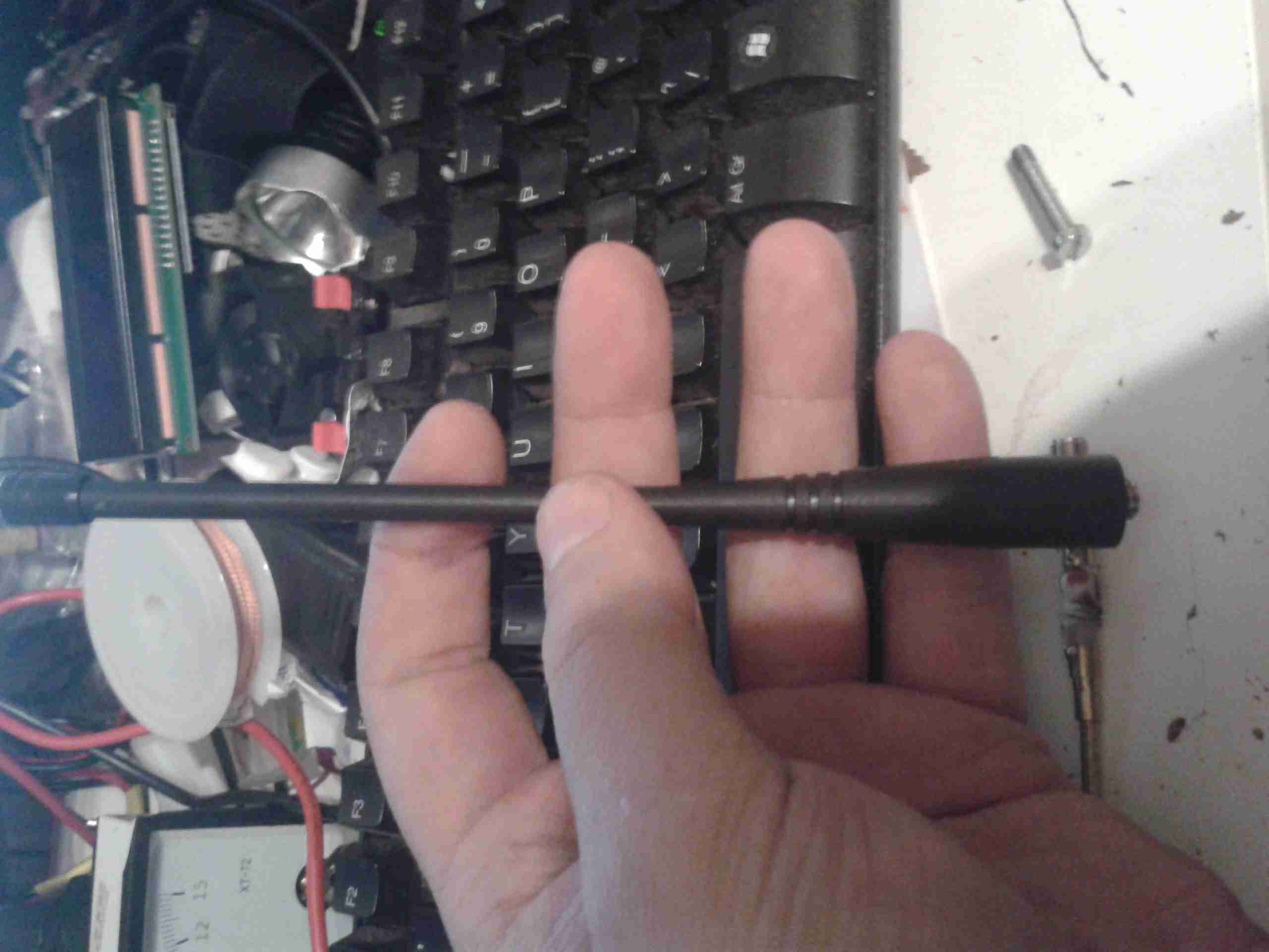
Stock Antenna
Here’s the antenna, just the factory rubber duckie. As with all these antennas, they’re a compromise between size & their efficiency.
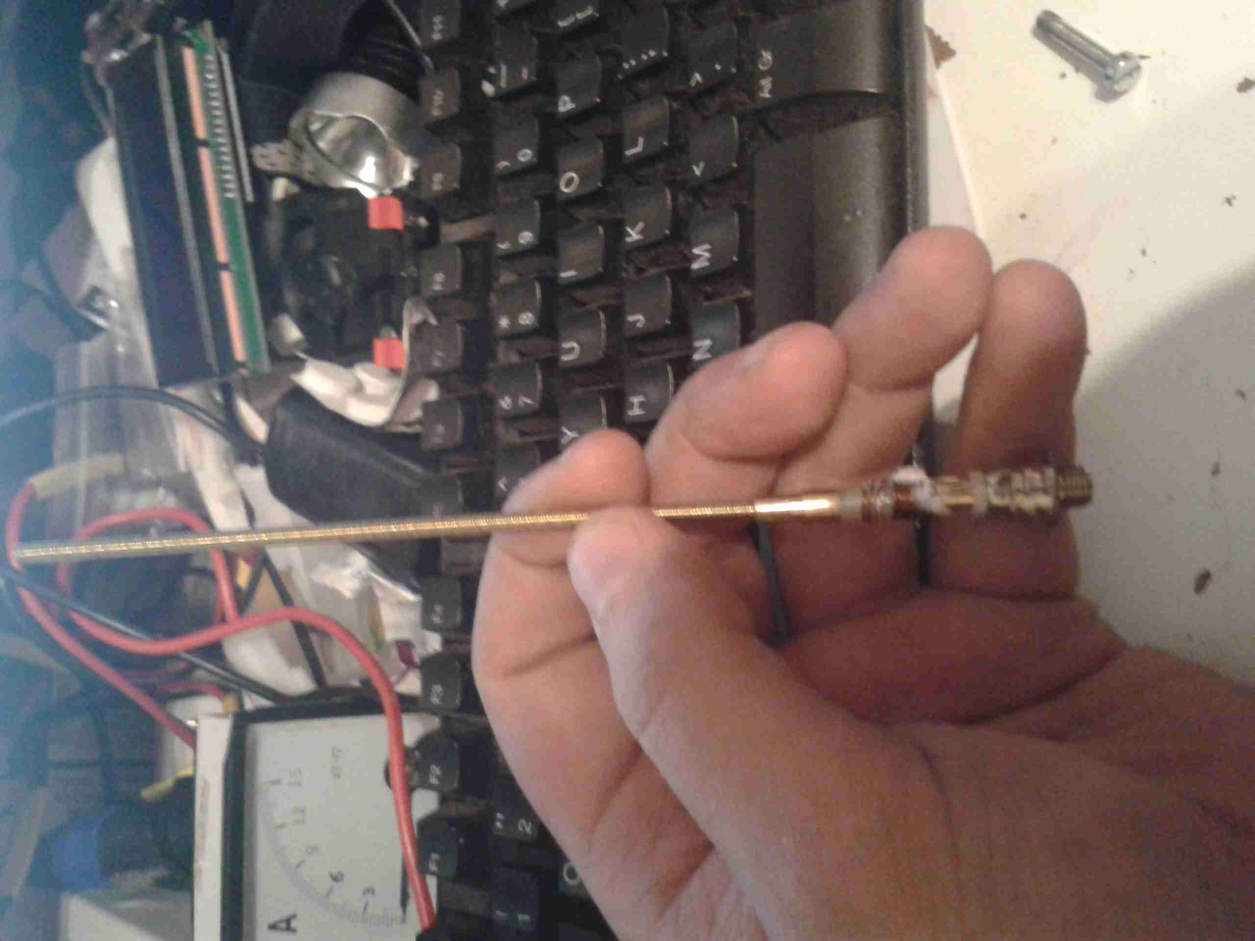
Naked Antenna!
Giving a gentle pull to the antenna sheath while it’s attached to the radio allows it to come apart. The quality actually doesn’t look to bad. It’s very similar in construction to my Diamond X-30, just on a much smaller scale.
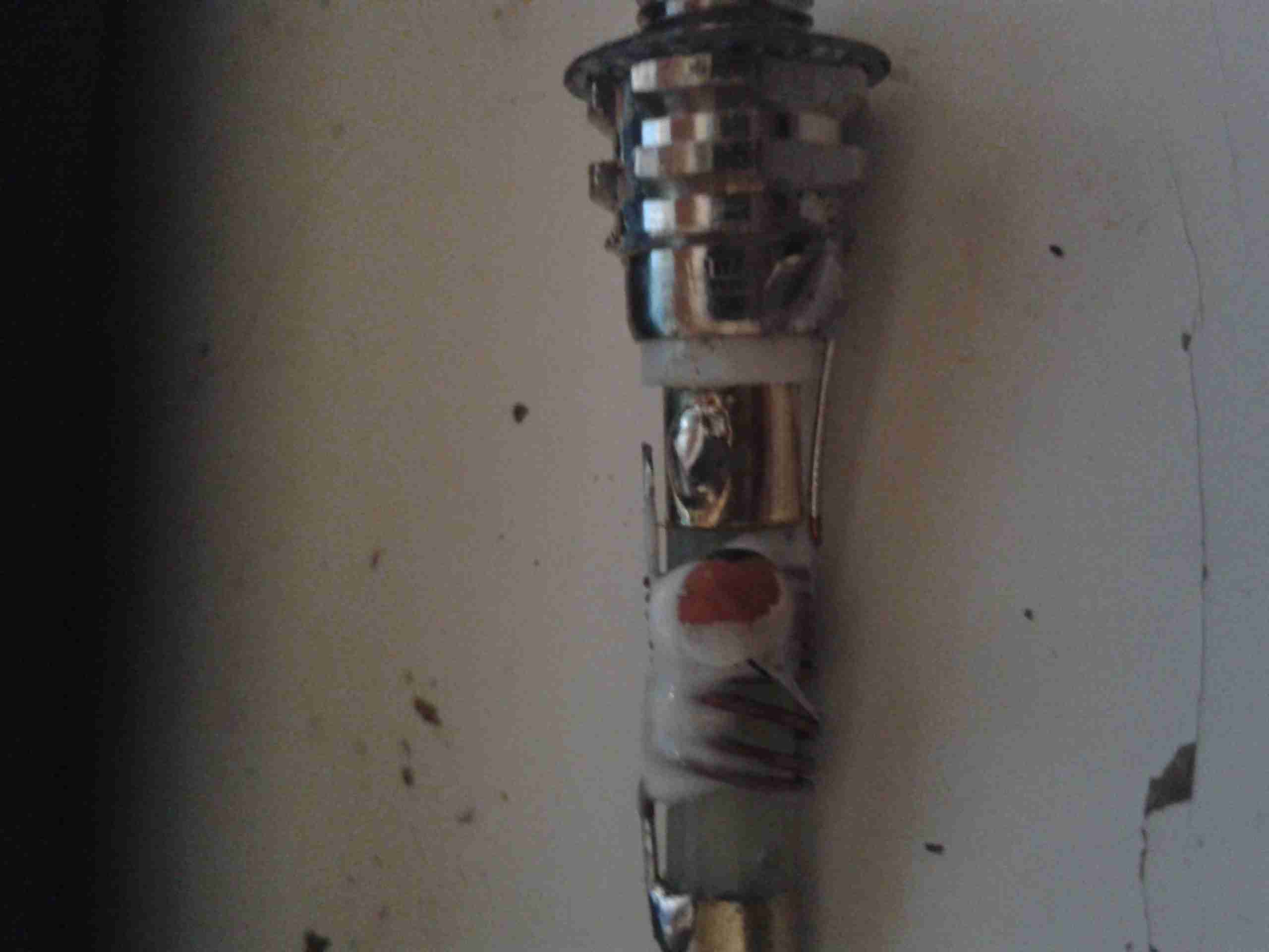
At the bottom of the antenna is the matching network, an inductor & ceramic disc capacitor. Here lies the problem with this antenna.
Dry Joint
Here where the capacitor joins onto the feedpoint from the SMA connector, the solder joint has come away. This was a very poor joint to start with, and the solder hadn’t wetted the capacitor lead at all
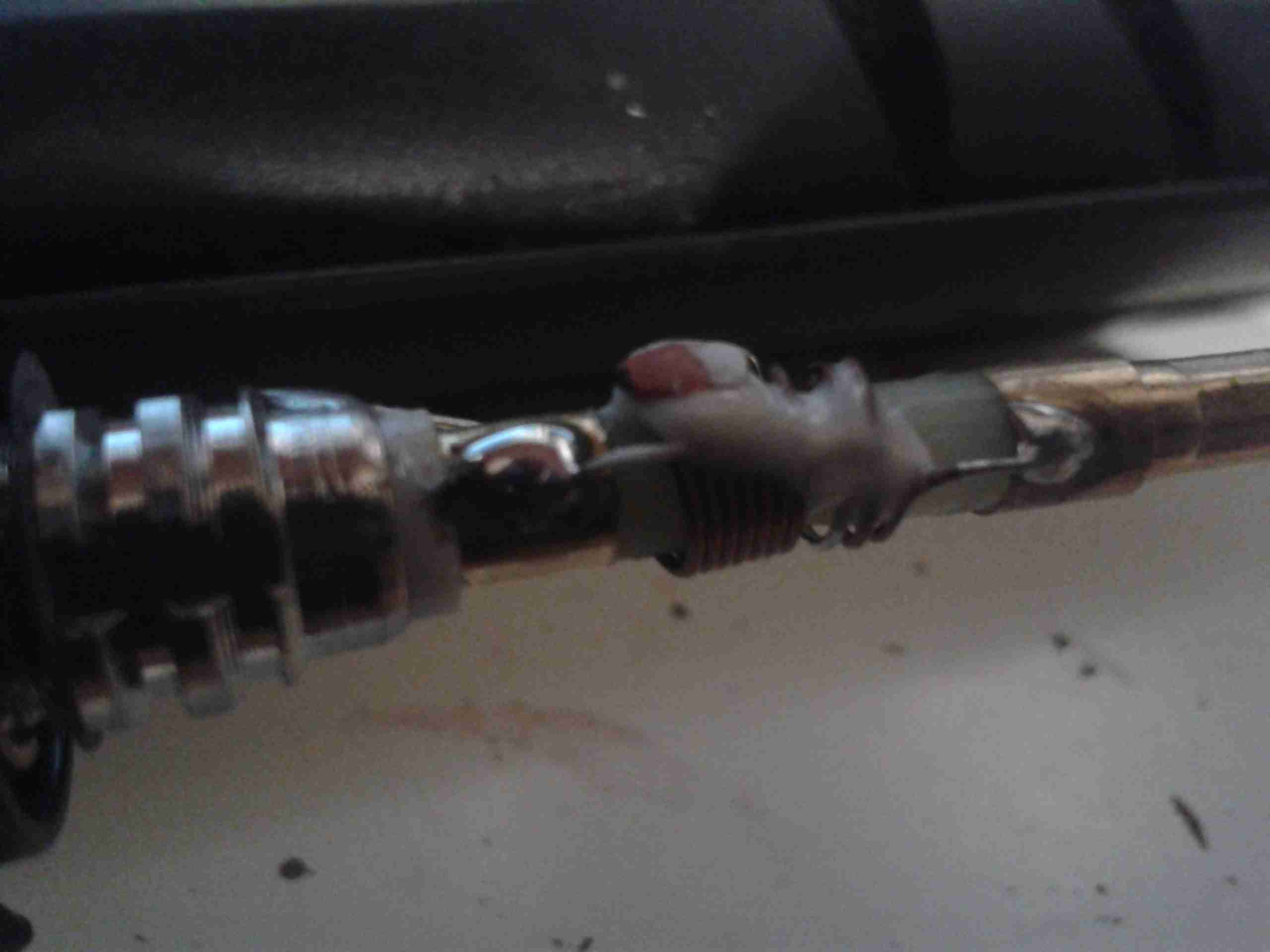
After cleaning the joint, and applying some flux, a new joint was easily made with some Real Solder.
Repaired Joint
Here’s the joint freshly repaired, the antenna is now back to full working order. It even seems to work better than the others I have 🙂
Here is an old fish tank external filter & a few pics of the insides.
Label
Label on the front of the pump head. Fittings on either side of the motor are water I/O.
Pump
Underside of the pump head, inlet is on the right, outlet from the pump is on the left. Pump intake in centre.
Pump Parts
Pump disassembled. This pump requires no shaft seals as the impeller is driven magnetically with a synchronous motor.
Filter Stack
Filter stack removed from the unit. From left: foam media, activated charcoal/gravel & ceramic pellets.
Tip Jar
If you’ve found my content useful, please consider leaving a donation by clicking the Tip Jar below!
All collected funds go towards new content & the costs of keeping the server online.