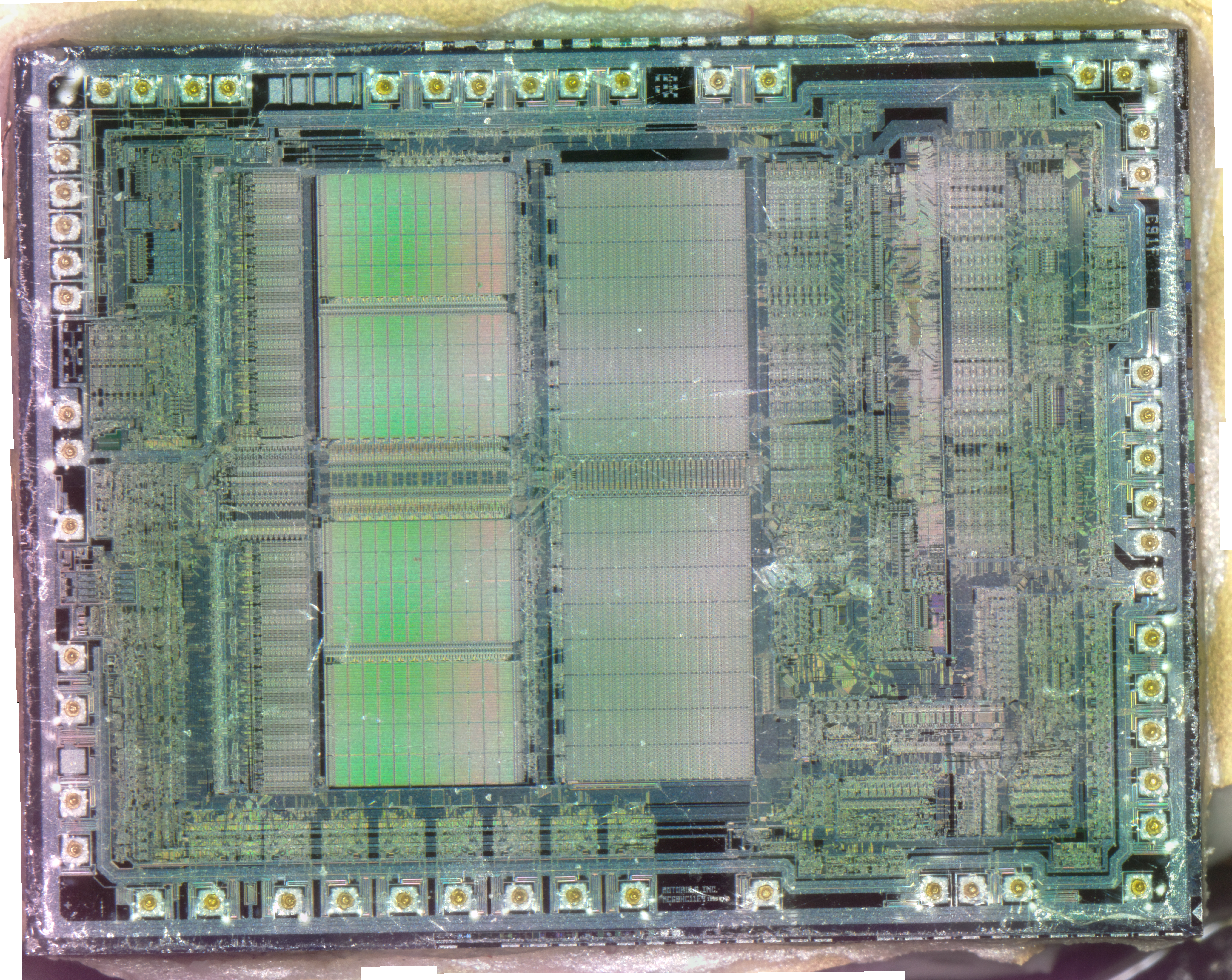
This particular IC came out of a very old VHF band radio, from the early 90’s. The die was encased in a custom ceramic package, like every other IC in the radio, with a custom part number. I managed to identify it from the markings on the silicon.
Motorola MC68HC11L6
This was a pretty powerful MCU for it’s time, with 16K of onboard ROM, 512 bytes of both RAM & EEPROM, a 16-bit timer, 8-bit ADC, SPI & a MC68HC11 CPU core.
Following on from the earlier power tests on my Baofeng HTs, here’s the readings from the Wouxun KG-UV950P. Power is a little lower than specified, but this is probably due to the supply voltage being a bit less than 13.8v. These readings were taken at a supply voltage of 12.88v.
The same frequencies were used, 145.500 & 433.500 for the VHF/UHF tests. For the 6/10m tests 27MHz & 50MHz were used.
The power meter was connected with 1 metre of RG58 dual-screened cable with N-type connectors.
I’ve noticed that the RF power output from the Chinese radios can be quite variable from model to model, and even from individual radios of the same model & batch.
I’ve bought an RF Power meter (GY561) to do some tests on the HTs I have at present.
All tests were performed with the radio fully charged & still on the charging base, to make sure the supply voltage remained constant at 8.4v throughout the tests.
Frequencies used were 145.500 & 433.500 for VHF & UHF respectively.
The power meter was connected with ~8″ of RG174 Coax.
In my original review, I noted that this radio was supplied with a SO-259 socket for the antenna connection.
However I’m less than fond of these, due to their non-constant impedance, which can cause signal loss issues at VHF/UHF. Because of this, I’ve replaced it with a high quality N-type connector. These connectors are much better, as they are a constant 50Ω impedance, they’re weather resistant, and being rated to 11GHz, are more than sufficient for a radio that will only do up to 70cm.
RF Output Jack
Here can be seen the point where the connection is made to the PCB.
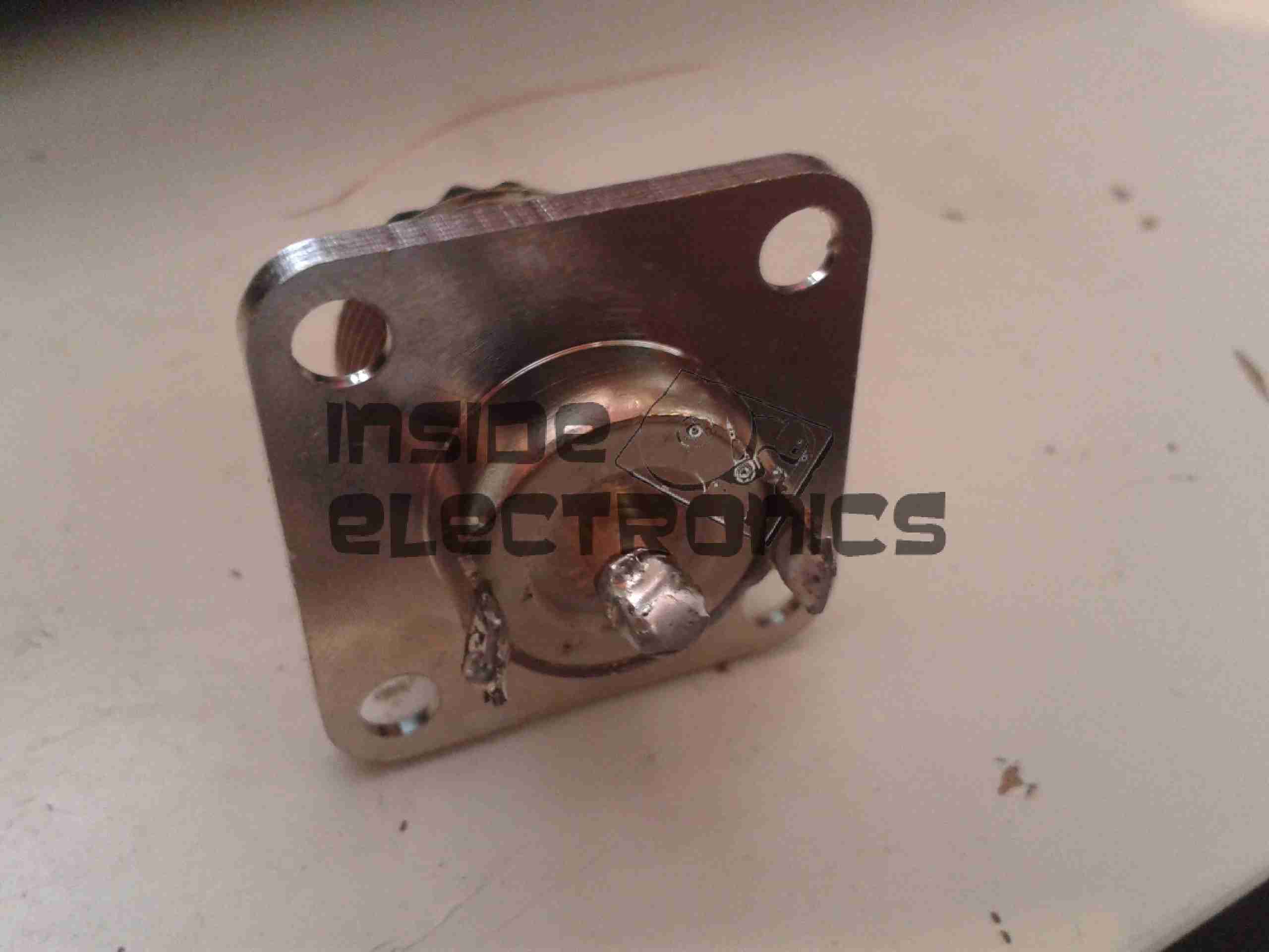
I’ve already replaced the socket in this photo. The pair of solder pads either side of the central RF point were soldered to wings on the back of the original SO-259. As there are a pair of screws, also connected to the ground plane, there have been no signal issues with just using the frame of the radio as the ground point. Shown below is the original socket, with the ground wings.
Original SO-259
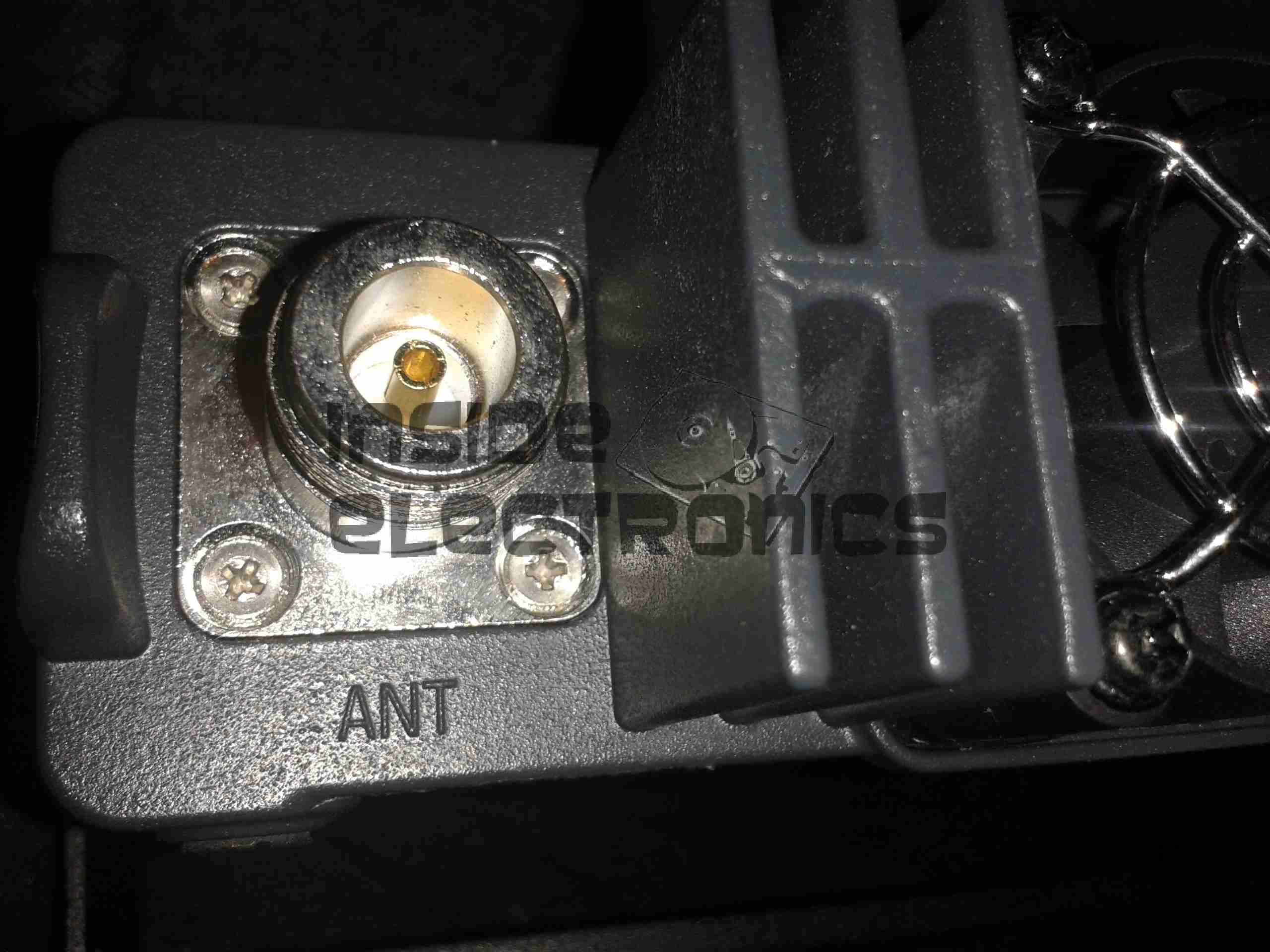
Finally, here is the back of the radio with it’s shiny new N connector.
New Connection
Chassis mount connectors are pretty standard, so this new connector fits perfectly into the same recess of the original. Looks like factory fitted!
I am now standardising on N connectors for everything in my radio shack, next on the project list for conversion is the SWR meter I recently acquired.
Here is the casing split, with the main CPU board & display on the right, & the RF tranciever board on the left.
Main CPU
View of the main CPU board, with the mic & loudspeaker on the right hand side.
The channel display is on the reverse side of the PCB.
RF Board
View of the RF board, with it’s brass shielding attached. This radio will transmit at 5W max.
RF Shields Removed
Shielding removed, power regulation bottom right corner of the board, tranciever on the left.
PCB Front
CPU board removed from the casing, showing the LCD & the user buttons to the left.
Tip Jar
If you’ve found my content useful, please consider leaving a donation by clicking the Tip Jar below!
All collected funds go towards new content & the costs of keeping the server online.