Being in technology for a long time, I have seen my fair share of disk failures. However I have never seen a single instance where SMART has issued a sufficient warning to backup any data on a failing disk. The following is an example of this in action.
Toshiba MQ01ABD050
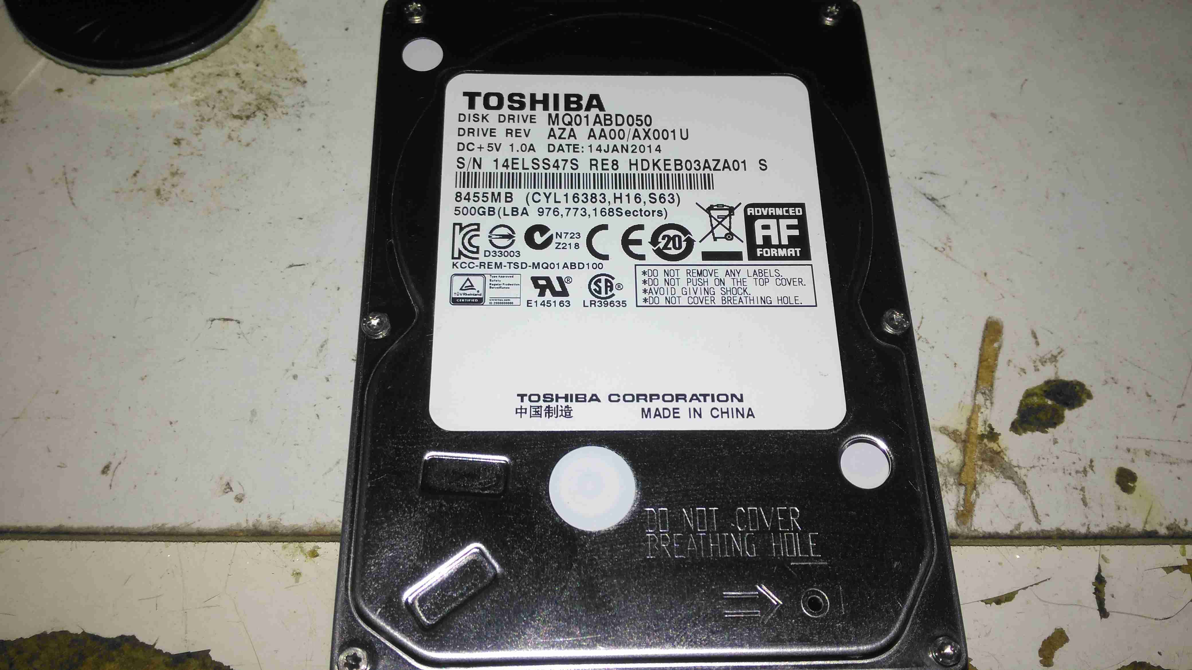
Here is a 2.5″ Toshiba MQ01ABD050 500GB disk drive. This unit was made in 2014, but has a very low hour count of ~8 months, with only ~5 months of the heads being loaded onto the platters, since it has been used to store offline files. This disk was working perfectly the last time it was plugged in a few weeks ago, but today within seconds of starting to transfer data, it began slowing down, then stopped entirely. A quick look at the SMART stats showed over 4000 reallocated sectors, so a full scan was initiated.
SMART Test Failure
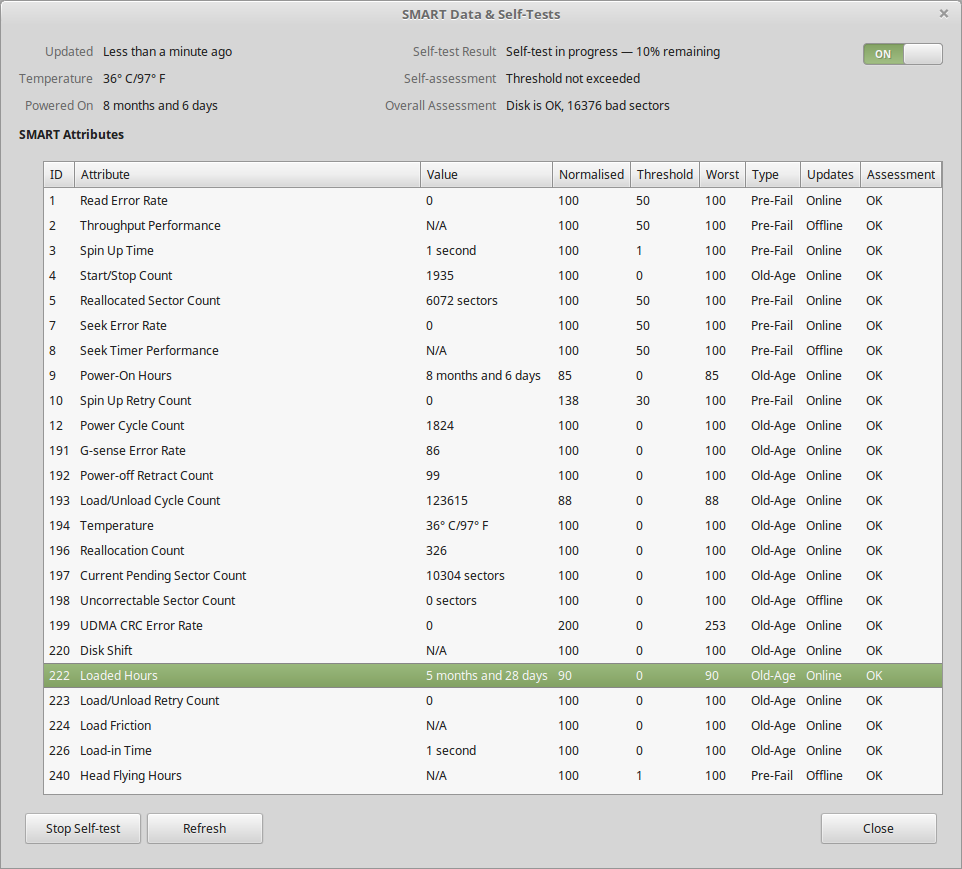
After the couple of hours an extended test takes, the firmware managed to find a total of 16,376 bad sectors, of which 10K+ were still pending reallocation. Just after the test finished, the disk began making the usual clicking sound of the head actuator losing lock on the servo tracks. Yet SMART was still insisting that the disk was OK! In total about 3 hours between first power up & the disk failing entirely. This is possibly the most sudden failure of a disk I’ve seen so far, but SMART didn’t even twig from the huge number of sector reallocations that something was amiss. I don’t believe the platters are at fault here, it’s most likely to be either a head fault or preamp failure, as I don’t think platters can catastrophically fail this quickly. I expected SMART to at least flag that the drive was in a bad state once it’s self-test completed, but nope.
Internals
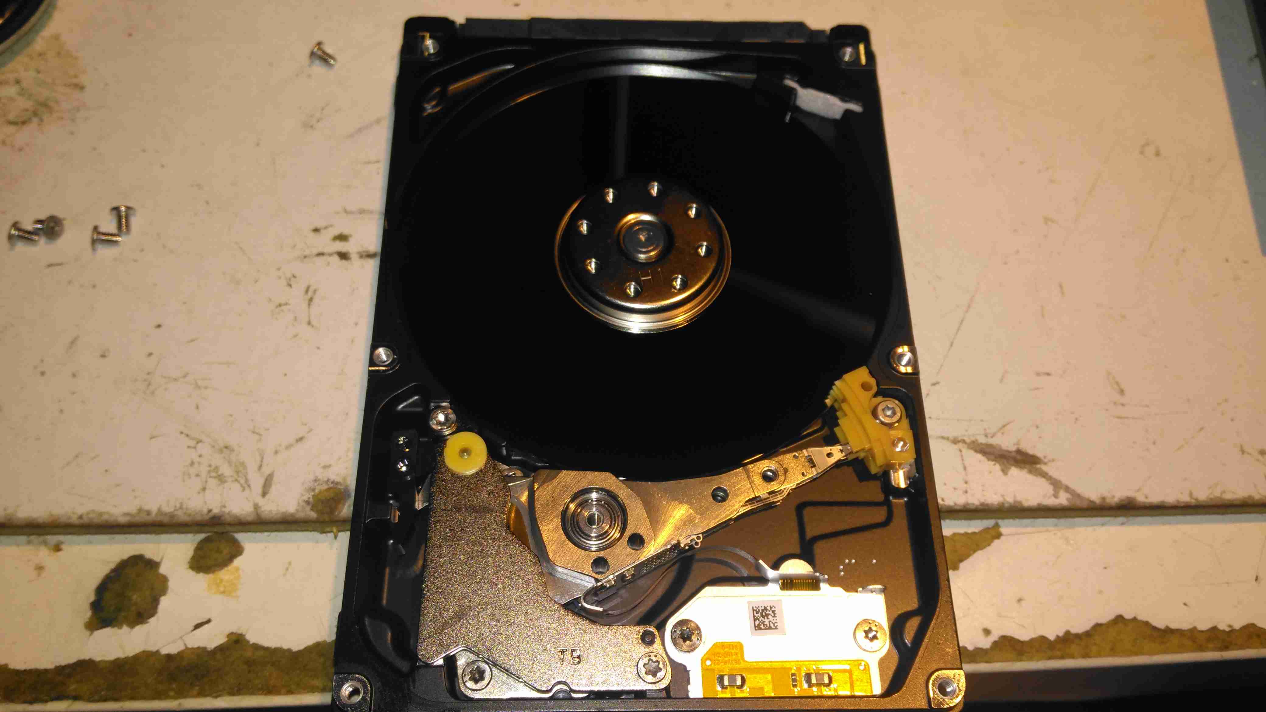
After pulling the lid on this disk, to see if there’s any evidence of a head crashing into a platter, there’s nothing – at least on a macroscopic scale, the single platter is pristine. I’ve seen disks crash to the point where the coating has been scrubbed from the platters so thoroughly that they’ve been returned to the glass discs they started off as, with the enclosure packed full of fine black powder that used to be data layer, but there’s no indication of mechanical failure here. Electronic failure is looking very likely.
Clearly, relying on SMART to alert when a disk is about to take a dive is an unwise idea, replacing drives after a set period is much better insurance if they are used for critical applications. Of course, current backups is always a good idea, no matter the age of drive.
This is the teardown of a Zebra P330i plastic card printer, used for creating ID cards, membership cards, employee cards, etc. I got this as a faulty unit, which I will detail later on.
This printer supports printing on plastic cards from 1-30mils thick, using dye sublimation & thermal transfer type printing methods. Interfaces supplied are USB & Ethernet. The unit also has the capability to be fitted with a mag stripe encoder & a smart card encoder, for extra cost.
Print Engine
On the left here is the print engine open, the blue cartridge on the right is a cleaning unit, using an adhesive roller to remove any dirt from the incoming card stock.
This is extremely important on a dye sublimation based printing engine as any dirt on the cards will cause printing problems.
Cards In Feeder
Here on the right is the card feeder unit, stocked with cards. This can take up to 100 cards from the factory.
The blue lever on the left is used to set the card thickness being used, to prevent misfeeds. There is a rubber gate in the intake port of the printer which is moved by this lever to stop any more than a single card from being fed into the print engine at any one time.
Card Feeder Belt
Here is the empty card feeder, showing the rubber conveyor belt. This unit was in fact the problem with the printer, the drive belt from the DC motor under this unit was stripped, preventing the cards from feeding into the printer.
Print Head
Here is a closeup of the print head assembly. The brown/black stripe along the edge is the row of thin-film heating elements. This is a 300DPI head.
Print Station
This is under the print head, the black roller on the left is the platen roller, which supports the card during printing. The spool in the center of the picture is the supply spool for the dye ribbon.
In the front of the black bar in the bottom center, is a two-colour sensor, used to locate the ribbon at the start of the Yellow panel to begin printing.
LCD PCB
Inside the top cover is the indicator LCD, the back of which is pictured right.
This is a 16×1 character LCD from Hantronix. This unit has a parallel interface.
LCD
Front of the LCD, this is white characters on a blue background.
Roller Drive Belts
Here is the cover removed from the printer, showing the drive belts powering the drive rollers. There is an identical arrangement on the other side of the print engine running the other rollers at the input side of the engine.
Mains Filter
Here the back panel has been removed from the entire print engine, complete with the mains input wiring & RFI filtering.
This unit has excellent build quality, just what is to be expected from a £1,200+ piece of industrial equipment.
Main Frame With Motors
The bottom of the print engine, with all the main wiring & PCB removed, showing the main drive motors. The left hand geared motor operates the head lift, the centre motor is a stepper, which operates the main transmission for the cards. The right motor drives the ribbon take up spindle through an O-Ring belt.
Feeder Drive Motor
Card feeder drive motor, this connects to the belt assembly through a timing belt identical to the roller drive system.
All these DC geared motors are 18v DC, of varying torque ratings.
Power Supply
Here is the main power supply, a universal input switch-mode unit, outputting 24v DC at 3.3A.
PSU Label
PSU info. This is obviously an off the shelf unit, manufactured by Hitek. Model number FUEA240.
Print Engine Rear
The PSU has been removed from the back of the print engine, here is shown the remaining mechanical systems of the printer.
Print Engine Components
A further closeup of the print engine mechanical bay, the main stepper motor is bottom centre, driving the brass flywheel through another timing belt drive. The O-Ring drive on the right is for the ribbon take up reel, with the final motor driving the plastic cam on the left to raise/lower the print head assembly.
The brass disc at the top is connected through a friction clutch to the ribbon supply reel, which provides tension to keep it taut. The slots in the disc are to sense the speed of the ribbon during printing, which allows the printer to tell if there is no ribbon present or if it has broken.
RFID PCB
Here is a further closeup, showing the RFID PCB behind the main transmission. This allows the printer to identify the ribbon fitted as a colour or monochrome.
The antenna is under the brass interrupter disc on the left.
I/O Daughterboard
The I/O daughterboard connects to the main CPU board & interfaces all the motors & sensors in the printer.
Main PCB
Here is the main CPU board, which contains all the logic & processing power in the printer.
CPU
Main CPU. This is a Freescale Semiconductor part, model number MCF5206FT33A, a ColdFire based 32-bit CPU. Also the system ROM & RAM can be seen on the right hand side of this picture.
Ethernet Interface
Bottom of the Ethernet interface card, this clearly has it’s own RAM, ROM & FPGA. This is due to this component being a full Parallel interface print server.
Ethernet Interface Top
Top of the PCB, showing the main processor of the print server. This has a ferrite sheet glued to the top, for interference protection.
This is a little security measure you get with Internet Banking with the Co-Op, generates codes to confirm your identity using your bank card. About the size of a pocket calculator, this is the keypad & screen.
Card Slot
The rear of the unit, the card slots into the top, manufactured by Gemalto Digital Security.
Card Contacts
Outer back cover removed, showing the 8 contacts for the chip on the bank card, the 2 contacts below that switch on power when a card is inserted. Power comes from 2 lithium coin cells in the compartment on the lower left.
PCB Rear
PCB removed from the casing, showing the internal components. Two large pads at top left are battery connections, while the only IC on the board is the main CPU, under the card connector. 6MHz oscillator & 32Khz crystal on board for processing & timekeeping. LCD screen connection at far right.
Keypad Contacts
Reverse side of the PCB, with the keypad contacts. LCD on right, with programming interface pads at side of keypad.
Tip Jar
If you’ve found my content useful, please consider leaving a donation by clicking the Tip Jar below!
All collected funds go towards new content & the costs of keeping the server online.