Posted on Leave a comment

Is SMART Really Useful?

Being in technology for a long time, I have seen my fair share of disk failures. However I have never seen a single instance where SMART has issued a sufficient warning to backup any data on a failing disk. The following is an example of this in action.

Toshiba MQ01ABD050
Toshiba MQ01ABD050

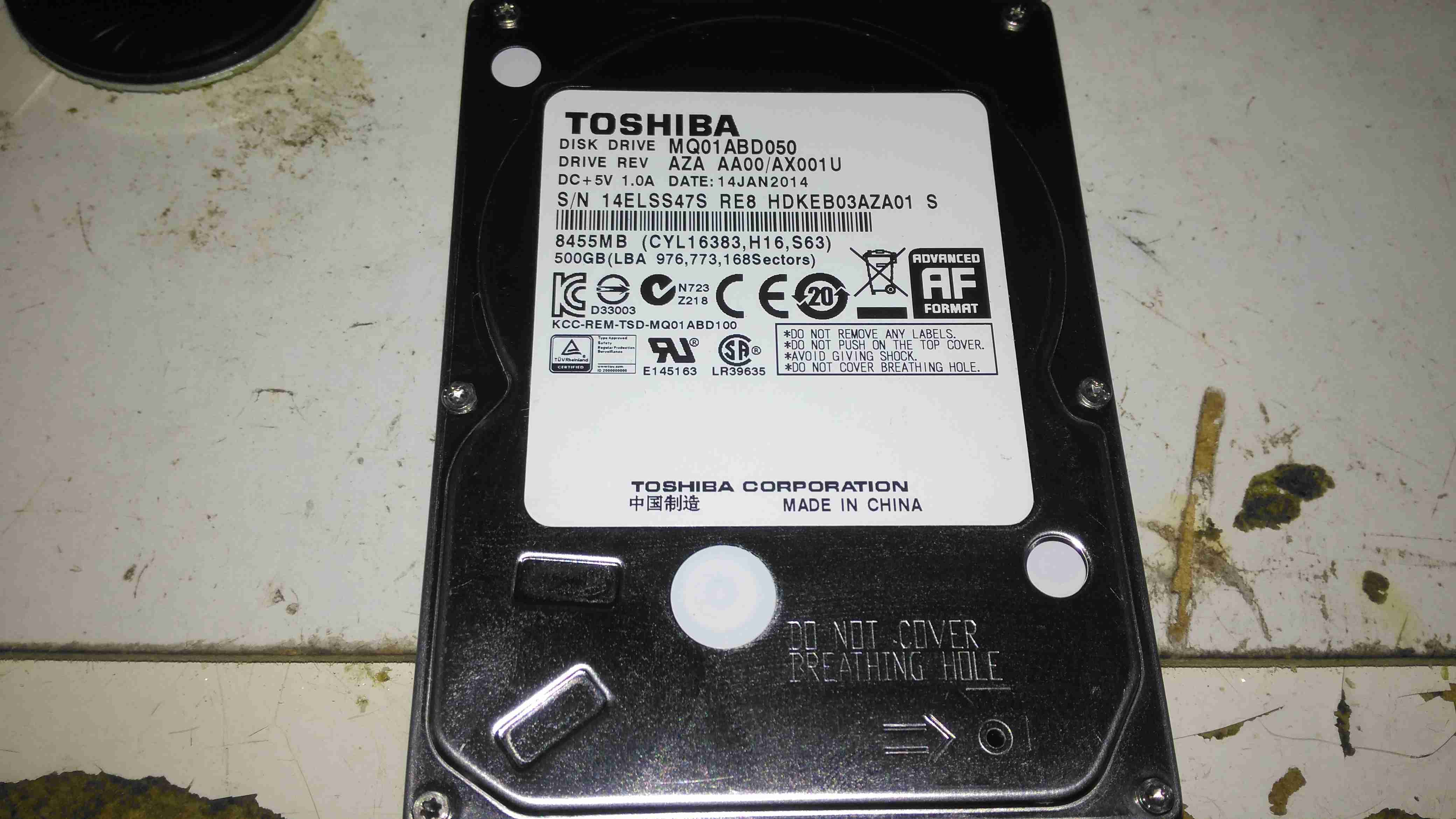
Here is a 2.5″ Toshiba MQ01ABD050 500GB disk drive. This unit was made in 2014, but has a very low hour count of ~8 months, with only ~5 months of the heads being loaded onto the platters, since it has been used to store offline files. This disk was working perfectly the last time it was plugged in a few weeks ago, but today within seconds of starting to transfer data, it began slowing down, then stopped entirely. A quick look at the SMART stats showed over 4000 reallocated sectors, so a full scan was initiated.

SMART Test Failure
SMART Test Failure

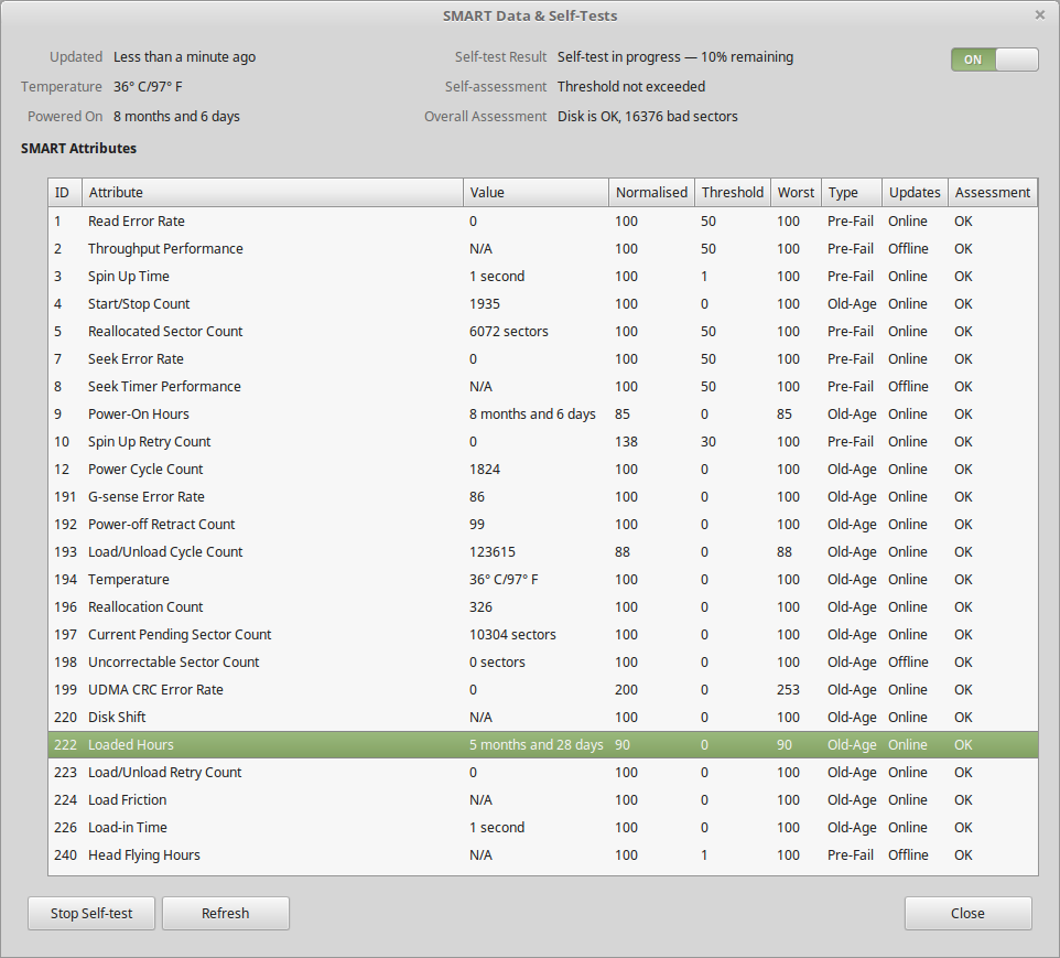
After the couple of hours an extended test takes, the firmware managed to find a total of 16,376 bad sectors, of which 10K+ were still pending reallocation. Just after the test finished, the disk began making the usual clicking sound of the head actuator losing lock on the servo tracks. Yet SMART was still insisting that the disk was OK! In total about 3 hours between first power up & the disk failing entirely. This is possibly the most sudden failure of a disk I’ve seen so far, but SMART didn’t even twig from the huge number of sector reallocations that something was amiss. I don’t believe the platters are at fault here, it’s most likely to be either a head fault or preamp failure, as I don’t think platters can catastrophically fail this quickly. I expected SMART to at least flag that the drive was in a bad state once it’s self-test completed, but nope.

Internals
Internals

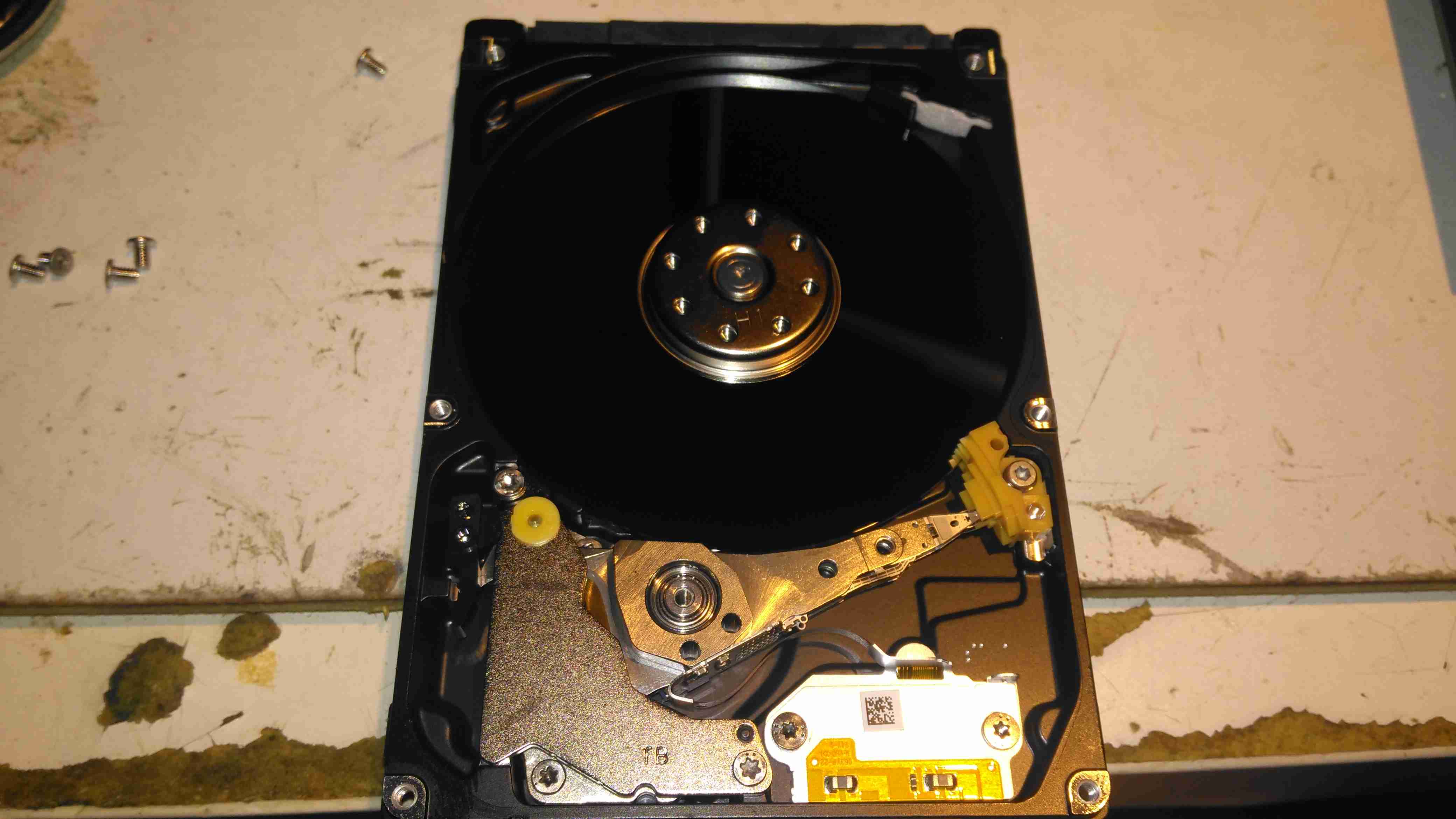
After pulling the lid on this disk, to see if there’s any evidence of a head crashing into a platter, there’s nothing – at least on a macroscopic scale, the single platter is pristine. I’ve seen disks crash to the point where the coating has been scrubbed from the platters so thoroughly that they’ve been returned to the glass discs they started off as, with the enclosure packed full of fine black powder that used to be data layer, but there’s no indication of mechanical failure here. Electronic failure is looking very likely.

Clearly, relying on SMART to alert when a disk is about to take a dive is an unwise idea, replacing drives after a set period is much better insurance if they are used for critical applications. Of course, current backups is always a good idea, no matter the age of drive.

Posted on Leave a comment

Another Viewfinder CRT

Here’s another viewfinder CRT, removed from a 1980’s vintage VHS camera I managed to get cheap from eBay.

This unit is very similar to the last one I posted about, although there are a few small differences in the control circuitry.

Viewfinder Schematic
Viewfinder Schematic – Click to Embiggen

Here’s the schematic, showing all the functional blocks of the viewfinder circuitry. An integrated viewfinder IC is used, which generates all the required scan waveforms for the CRT.
On the left is the input connector, with the power & video signals. Only pins 2 (GND), 3 (Composite video), & 4 (+8v) are needed here. Pin 1 outputs a horizontal sync signal for use elsewhere in the camera, while pin 5 fed the recording indicator LED.

To make connection easier,  I have rearranged the wires in the input connector to a more understandable colour scheme:

Input Connector
Input Connector

Red & Blue for power input, & a coax for the video. For the video GND connection, I have repurposed the Rec. LED input pin, putting a shorting link across where the LED would go to create a link to signal ground. Keeping this separate from the power GND connection reduces noise on the CRT.

Viewfinder CRT Assembly

Here’s the complete assembly liberated from it’s plastic enclosure.

PCB Closeup
PCB Closeup

Closeup of the control PCB. The 3 potentiometers control the CRT brightness, focus & vertical size.

M01KGG007WB CRT
M01KGG007WB CRT

The tiny CRT. Only ~60mm in length, with an 18mm screen size. This tube runs on +2294v final anode voltage. Much higher than I expected.

Electron Gun Closeup

The electron gun assembly, with the cathode, focus & final anode cups.

Phosphor Screen
Phosphor Screen

This screen is just a little bigger than a UK 5p piece! A marvel of precision engineering.


Posted on Leave a comment

ICL Barcode Scanner

Top
Top

An ICL barcode scanner from the 80s is shown here. This is the top of the unit with cover on.

Cover Removed
Cover Removed

Plastic cover removed from the unit showing internal components. Main PSU on left, scan assembly in center. Laser PSU & Cooling fan on right. Laser tube at top.

Scan Motor
Scan Motor

Closeup of laser scan motor. This unit scans the laser beam rapidly across the glass plate to read the barcode.

Controller PCB
Controller PCB

View of the bottom of the unit, showing the controller PCB in the centre.

Scan Motor Driver
Scan Motor Driver

The 3-phase motor driver circuit for the scan motor. 15v DC powered.

Laser Unit
Laser Unit

This is the laser unit disconnected from the back of the scanner. HT PSU is on right hand side, beam emerges from optics on left.

Laser Unit Label
Laser Unit Label

This unit is date stamped 1987. The oldest laser unit i own.

Tube PSU
Tube PSU

Laser tube power supply. Input voltage: 24v DC. Output: 1.8kV 4mA.

Laser PSU Board
Laser PSU Board

Rear of HT PSU. Obviously the factory made a mistake or two 🙂

Laser Tube Mounting
Laser Tube Mounting

Top cover removed from the laser unit here shows the 1mW He-Ne tube. Manufactured by Aerotech.

Tube Label
AeroTech He-Ne Tube

Tube label. Manufactured July 1993. Model LT06XR.

Plasma
Plasma

Here the tube has been removed from it’s mount to show the bore down the centre while energized.

OC Mirror
OC Mirror

OC end of the tube shown here lasing.

Beam
Beam

Beam output from the optics on the laser unit.

Tube Optics
Tube Optics

Optics built into the laser unit. Simple turning mirror on adjustable mount & collimating lens assembly.

Scan Lines
Scan Lines

Kind of hard to see but the unit is running here & projecting the scan lines on the top glass.

Laser Tube Mounting
Laser Tube Mounting

Laser tube mounting. A combo of spring clips & hot glue hold this He-Ne tube in place