Posted on Leave a comment

Another Viewfinder CRT

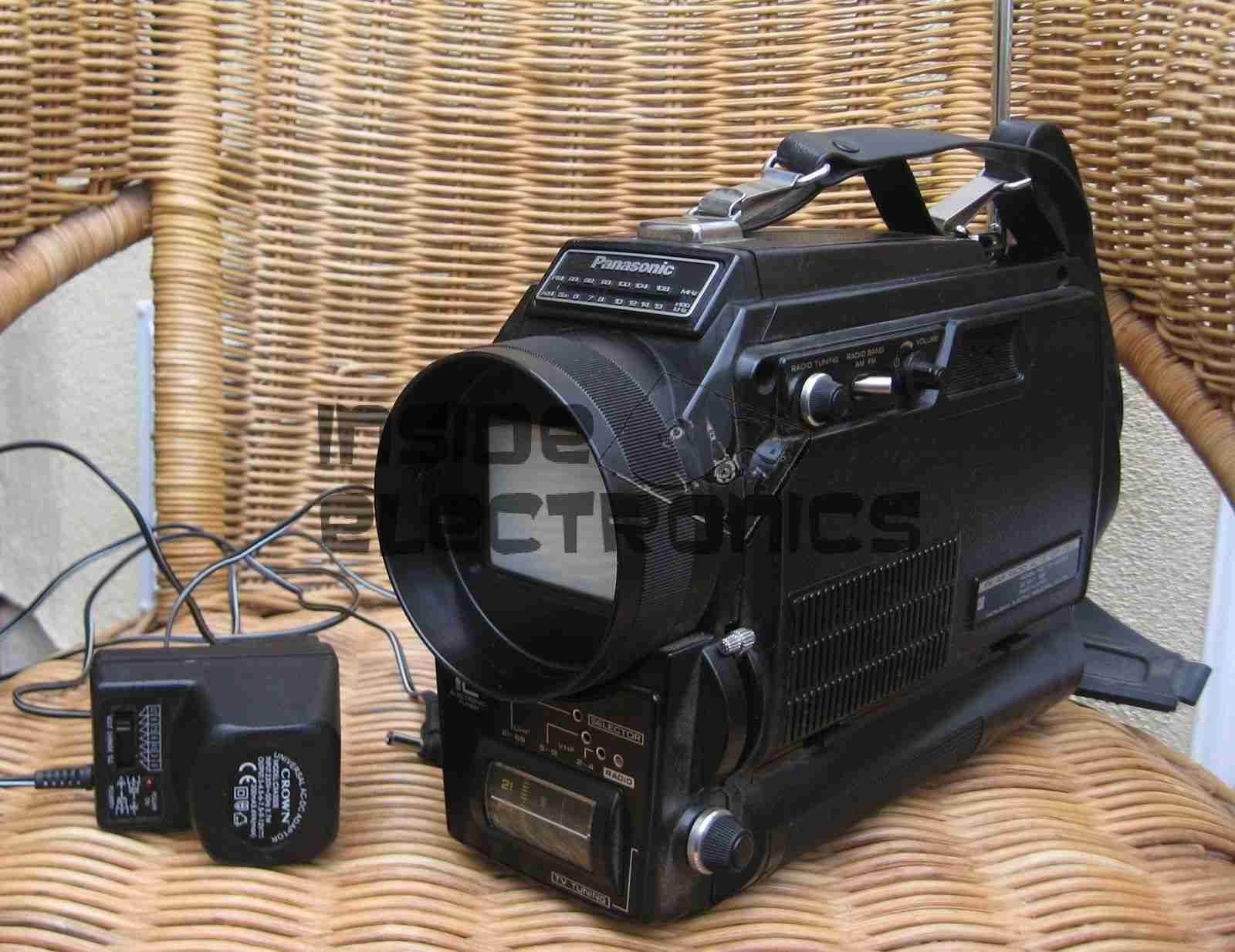
Here’s another viewfinder CRT, removed from a 1980’s vintage VHS camera I managed to get cheap from eBay.

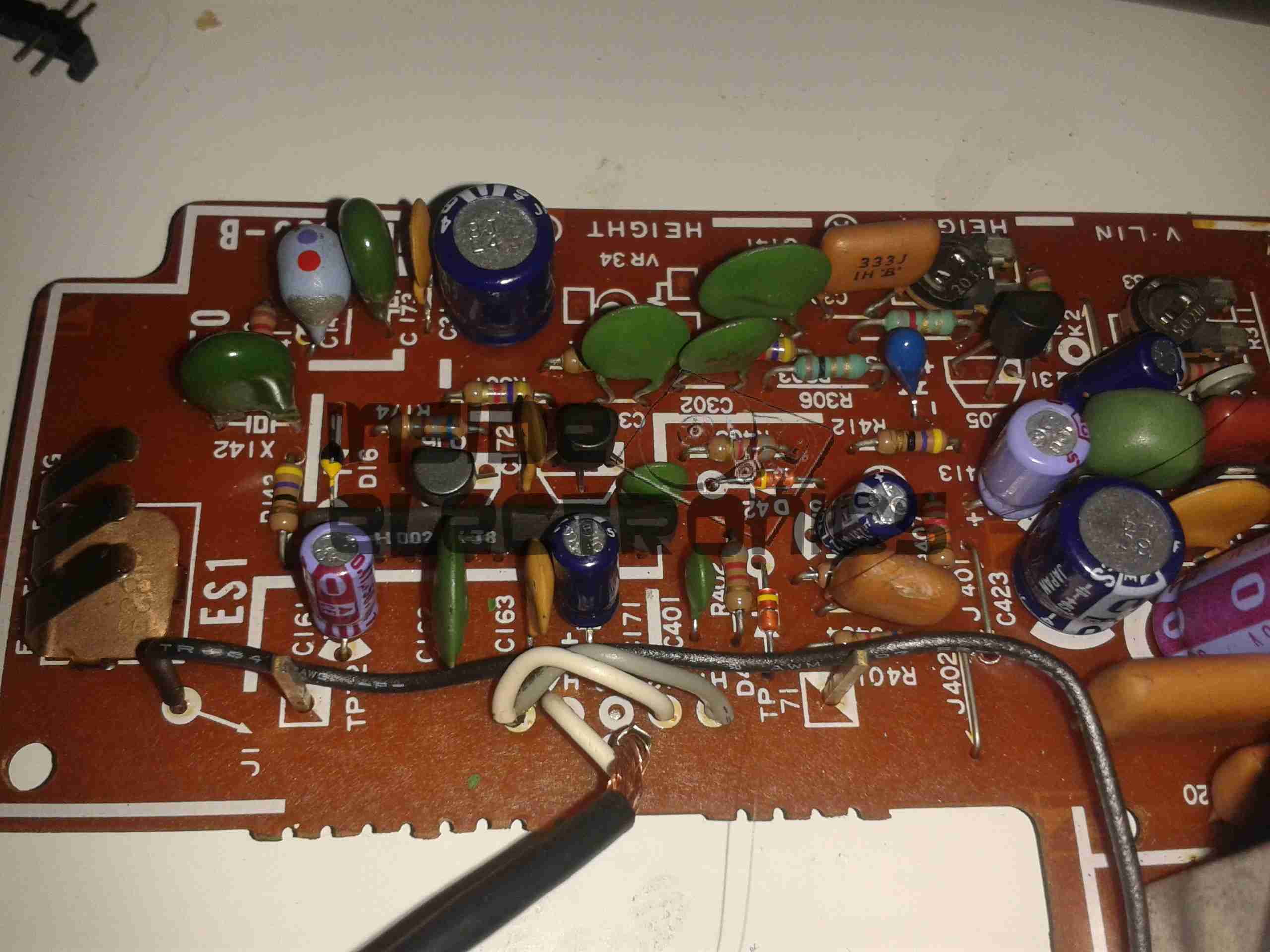
This unit is very similar to the last one I posted about, although there are a few small differences in the control circuitry.

Viewfinder Schematic
Viewfinder Schematic – Click to Embiggen

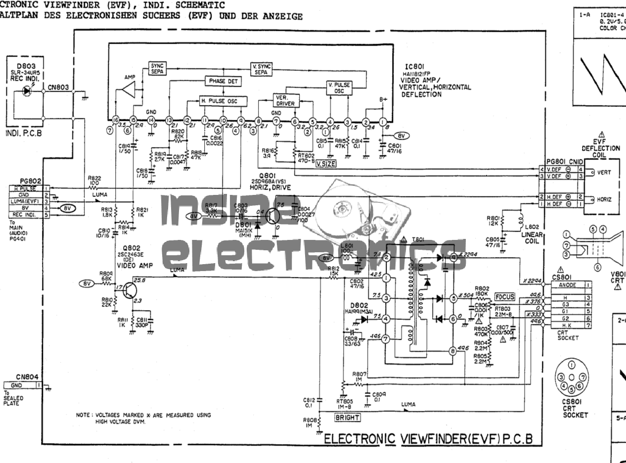
Here’s the schematic, showing all the functional blocks of the viewfinder circuitry. An integrated viewfinder IC is used, which generates all the required scan waveforms for the CRT.
On the left is the input connector, with the power & video signals. Only pins 2 (GND), 3 (Composite video), & 4 (+8v) are needed here. Pin 1 outputs a horizontal sync signal for use elsewhere in the camera, while pin 5 fed the recording indicator LED.

To make connection easier,  I have rearranged the wires in the input connector to a more understandable colour scheme:

Input Connector
Input Connector

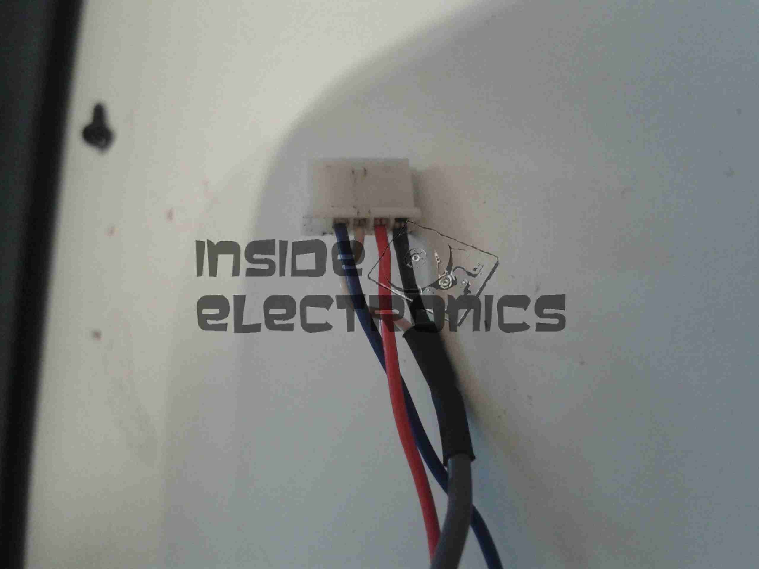
Red & Blue for power input, & a coax for the video. For the video GND connection, I have repurposed the Rec. LED input pin, putting a shorting link across where the LED would go to create a link to signal ground. Keeping this separate from the power GND connection reduces noise on the CRT.

Viewfinder CRT Assembly

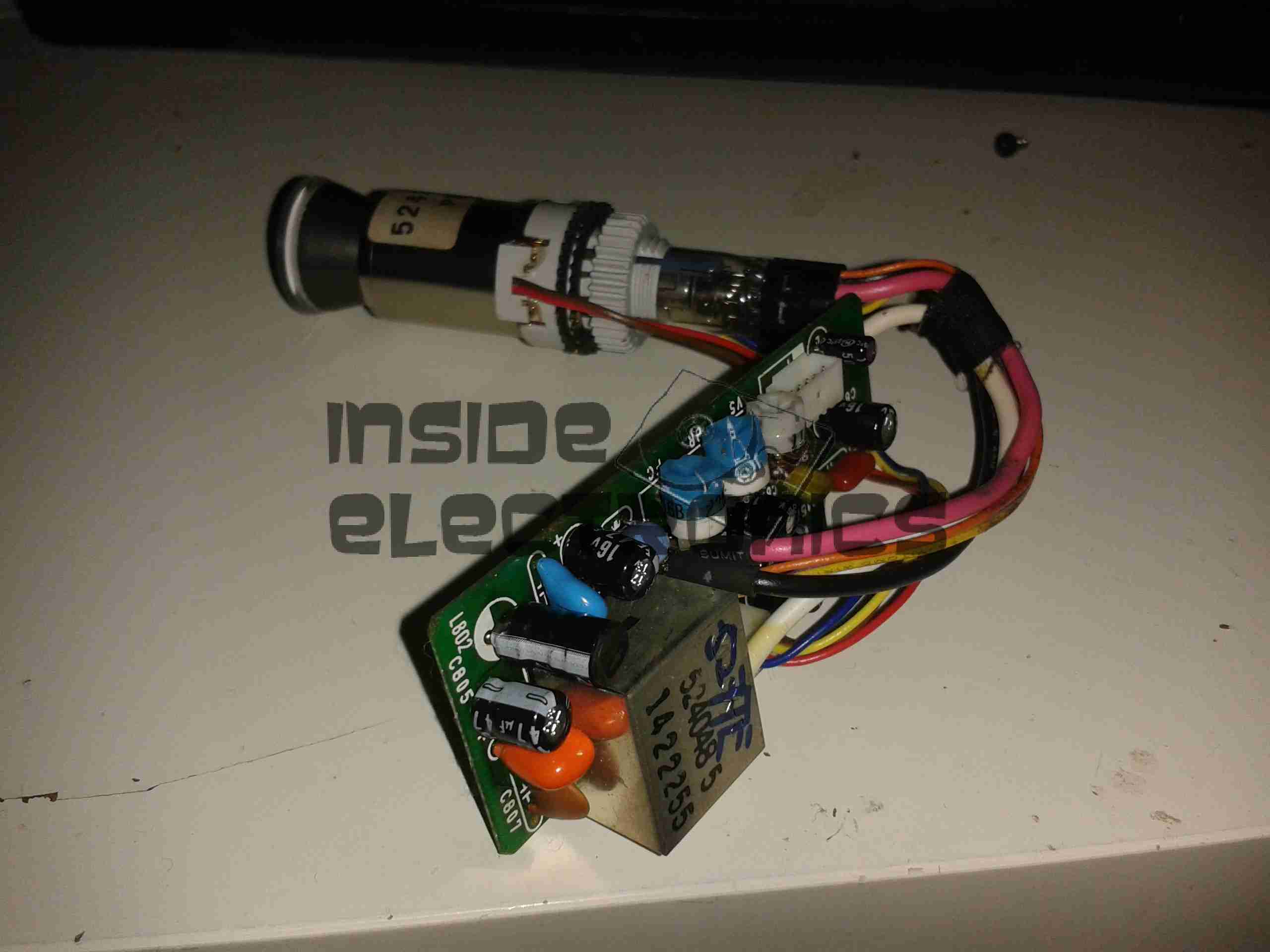
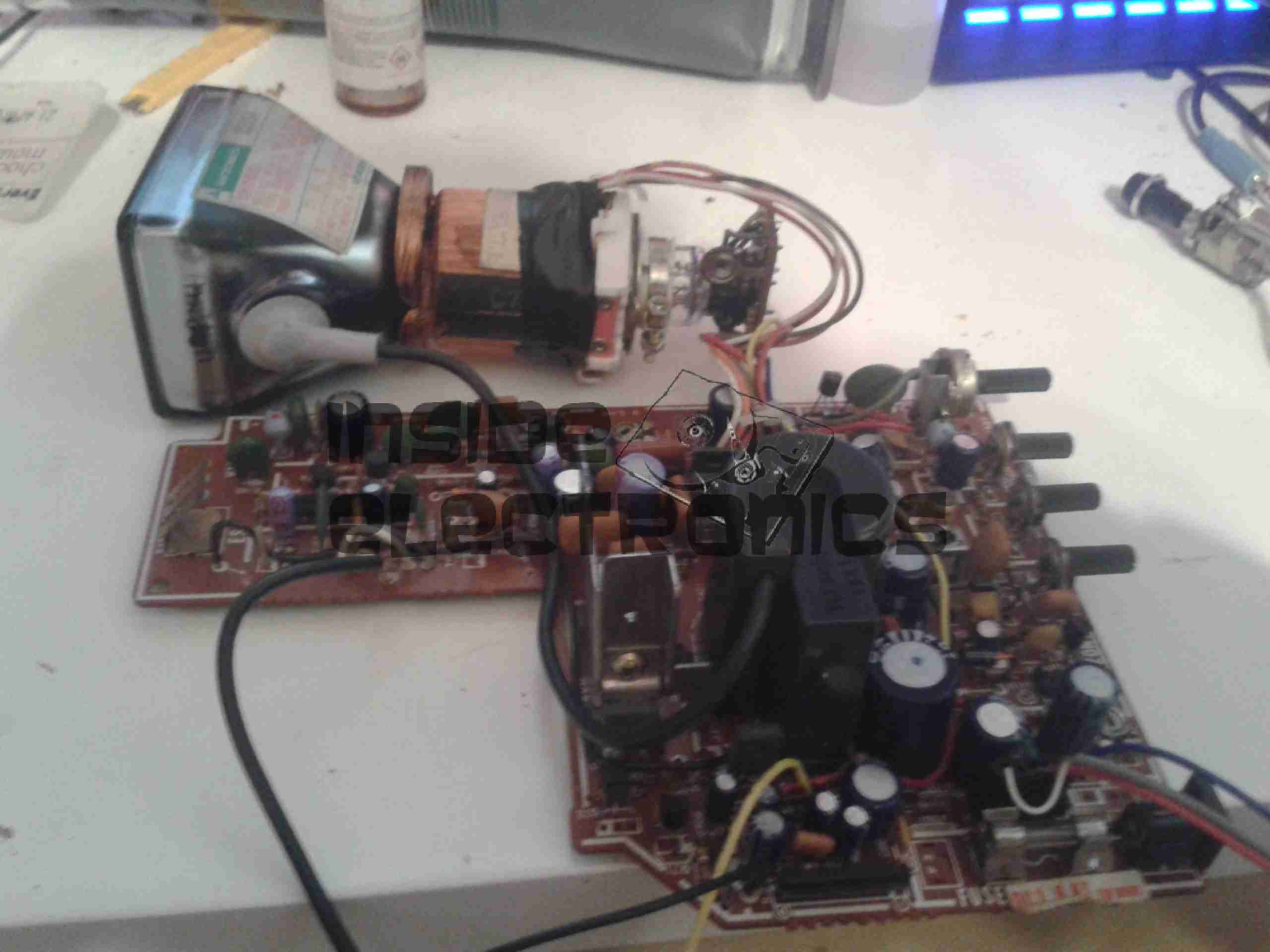
Here’s the complete assembly liberated from it’s plastic enclosure.

PCB Closeup
PCB Closeup

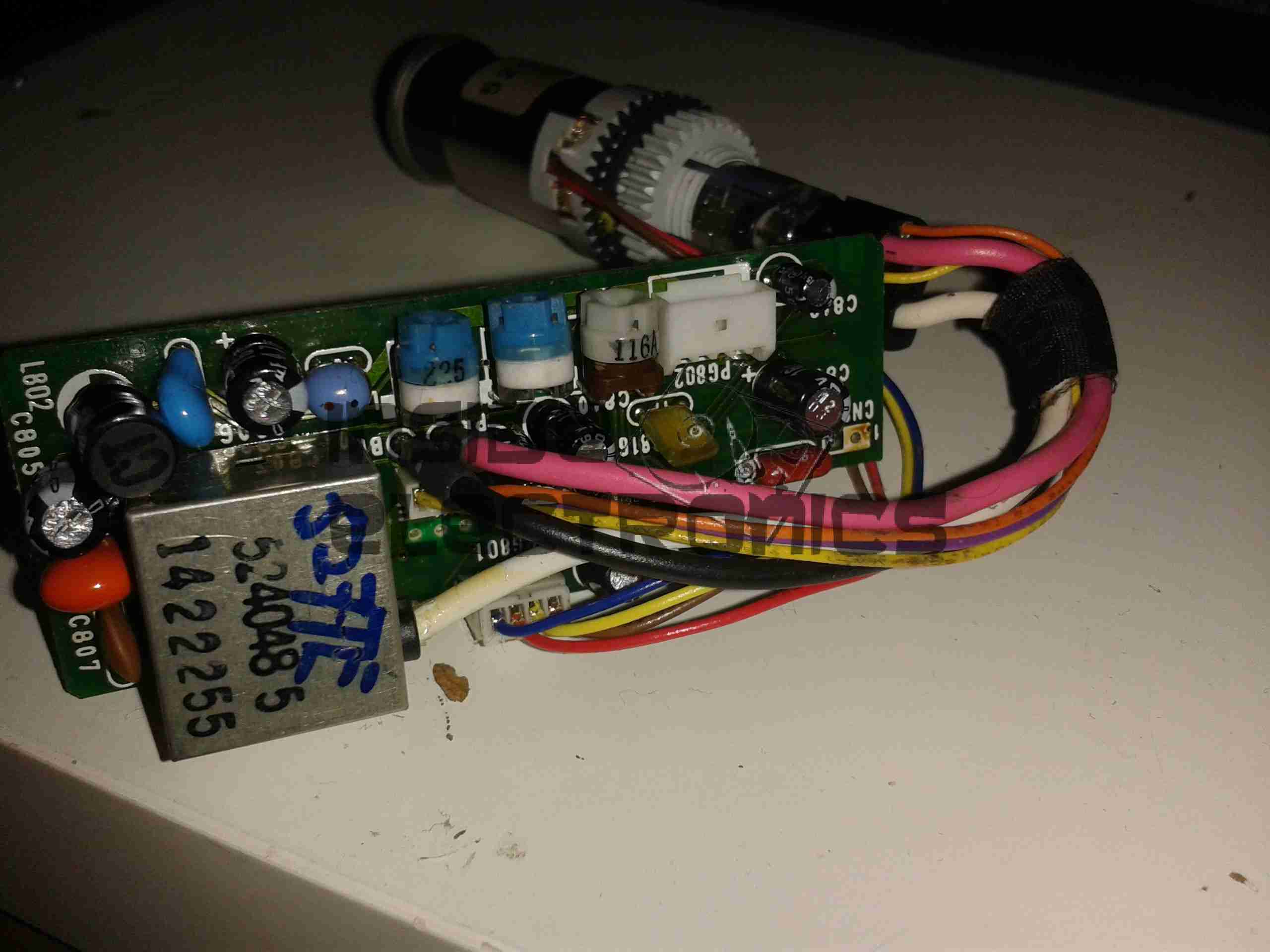
Closeup of the control PCB. The 3 potentiometers control the CRT brightness, focus & vertical size.

M01KGG007WB CRT
M01KGG007WB CRT

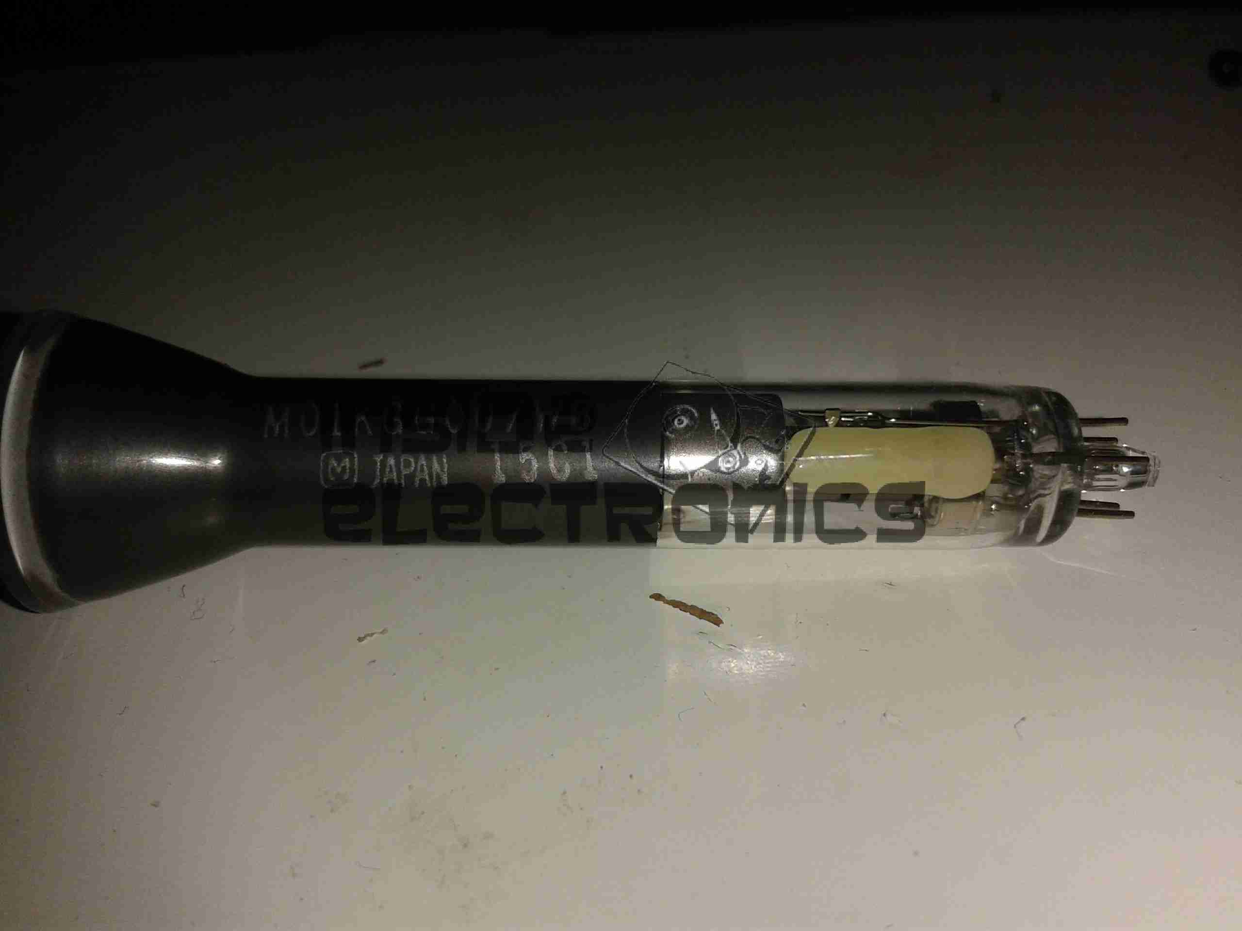
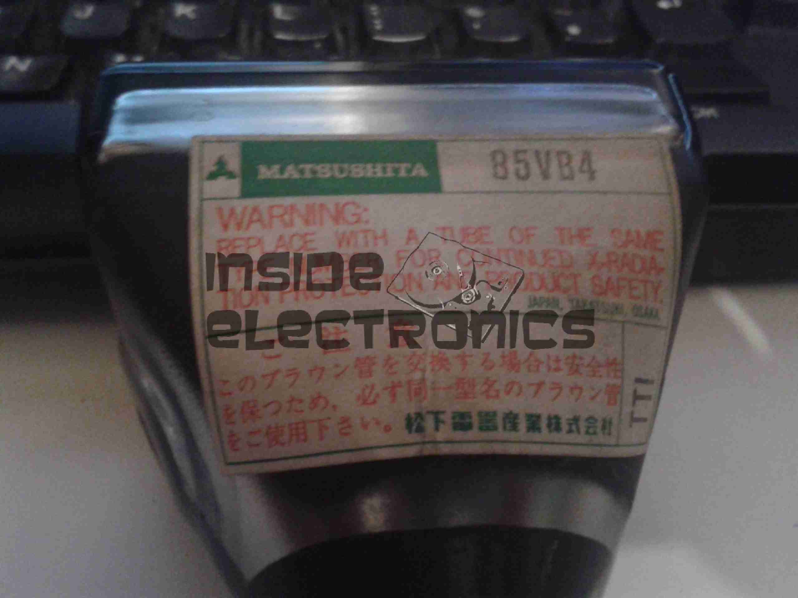
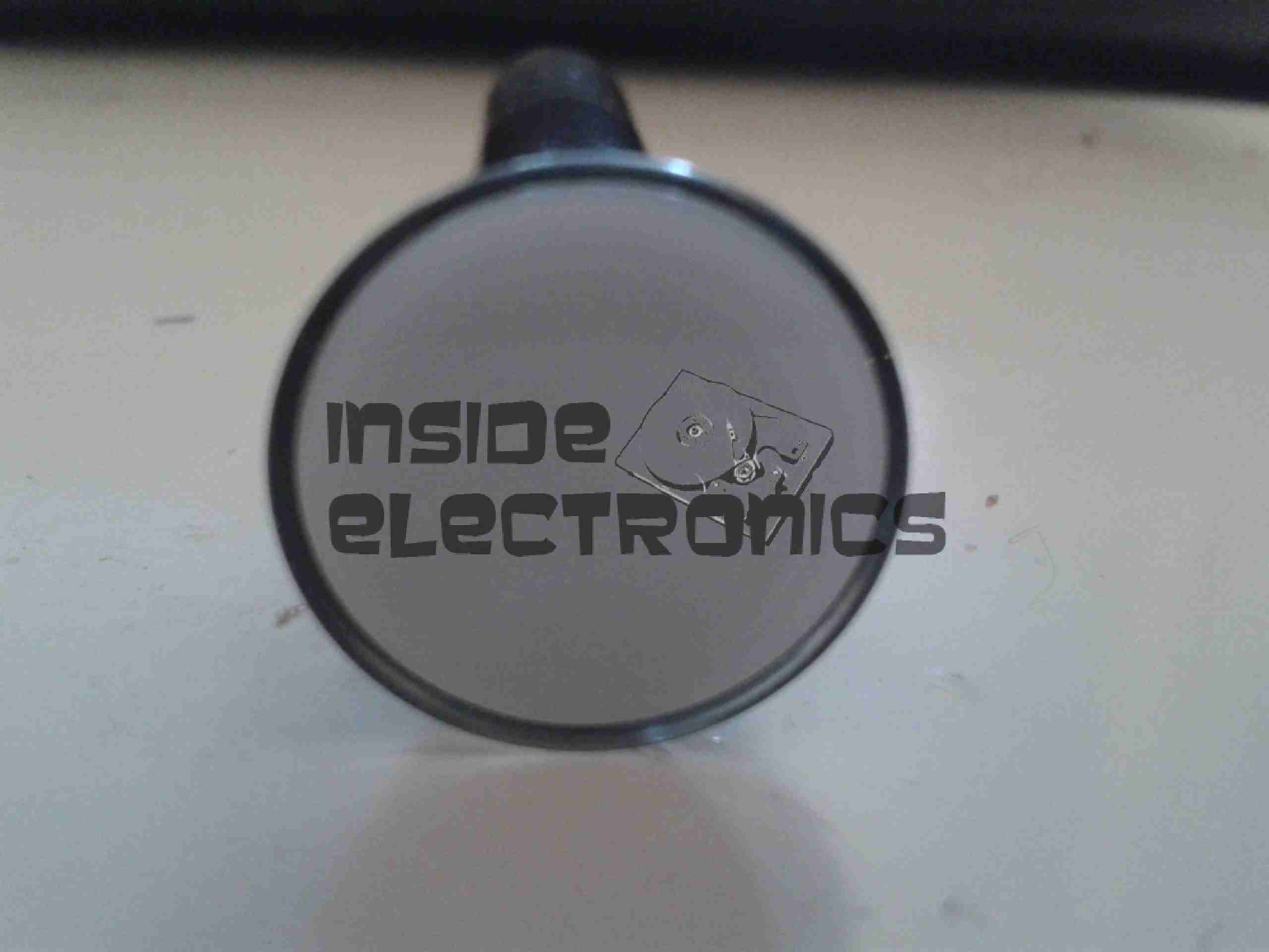
The tiny CRT. Only ~60mm in length, with an 18mm screen size. This tube runs on +2294v final anode voltage. Much higher than I expected.

Electron Gun Closeup

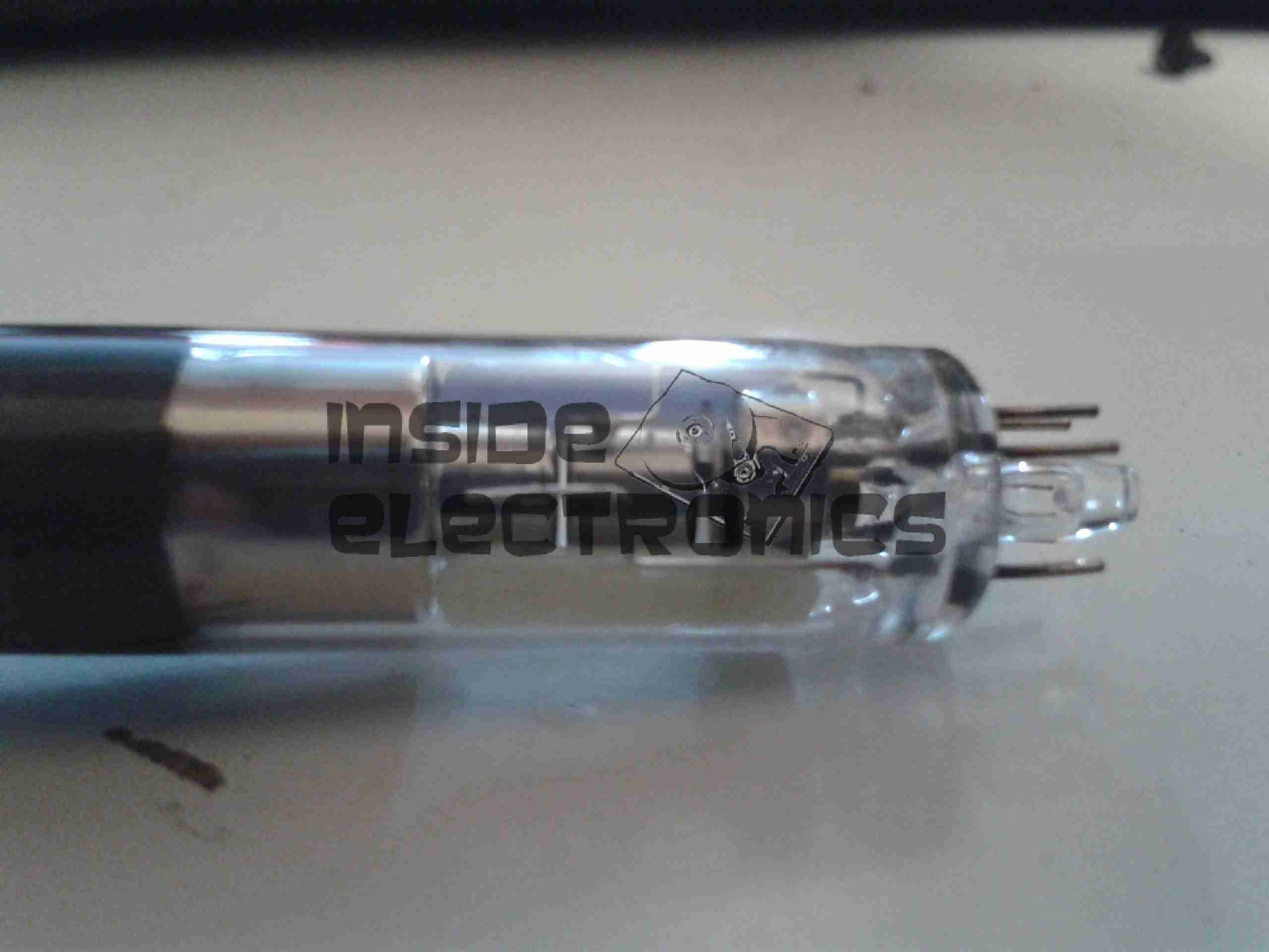
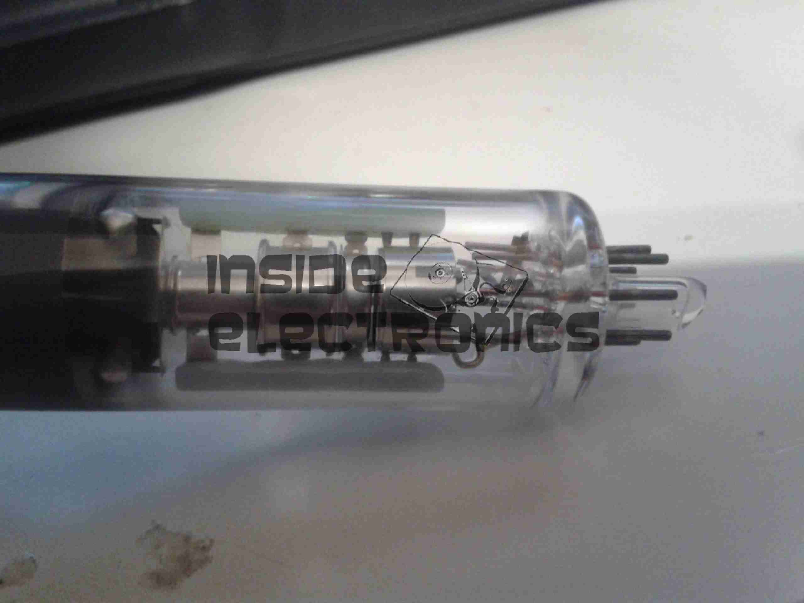
The electron gun assembly, with the cathode, focus & final anode cups.

Phosphor Screen
Phosphor Screen

This screen is just a little bigger than a UK 5p piece! A marvel of precision engineering.


Posted on 7 Comments

3″ CRT Composite Monitor

CRT Module

I recently managed to score a 3″ B&W portable TV on eBay, a Panasonic TR-3000G. As these old units are now useless, thanks to the switch off of analogue TV signalling, I figured I could find a composite signal internally & drive the CRT with an external source.

Panasonic TR-3000G
Panasonic TR-3000G

Here’s the TV in it’s native state. Running from 9v DC, or 6 D size cells. I’m guessing from somewhere around the 1970’s. Here is the CRT & associated drive circuitry, removed from the casing:

CRT Module
CRT Module

After dissecting the loom wiring between the CRT board & the RF/tuner board, I figured out I had to short out Pins 1,2 & 5 on the H header to get the CRT to operate straight from the power switch. This board also generates the required voltages & signals to drive the RF tuner section. I have removed the loom from this, as the PCB operates fine without. It doesn’t seem to be fussy about power input either: it’s specified at 9v, but seems to operate fine between 7.5v & 14.5v DC without issue.

Video Connections
Video Connections

Tracing the wiring from the tuner PCB revealed a length of coax snaking off to the section marked Video/Sync. I successfully found the composite input!

Running OSMC
Running OSMC

A quick bit of wiring to a Raspberry Pi, & we have stable video! For such an old unit, the picture quality is brilliant, very sharp focus.

Matsushita 85VB4 CRT

Closeup of the CRT itself. I haven’t been able to find much data on this unit, but I’m guessing it’s similar to many commercial viewfinder CRTs.

Electron Gun Closeup

Amazingly, there isn’t a single IC in the video circuitry, it’s all discrete components. This probably accounts for the large overall size of the control PCB. Viewfinder CRTs from a few years later on are usually driven with a single IC & a few passives that provide all the same functions.