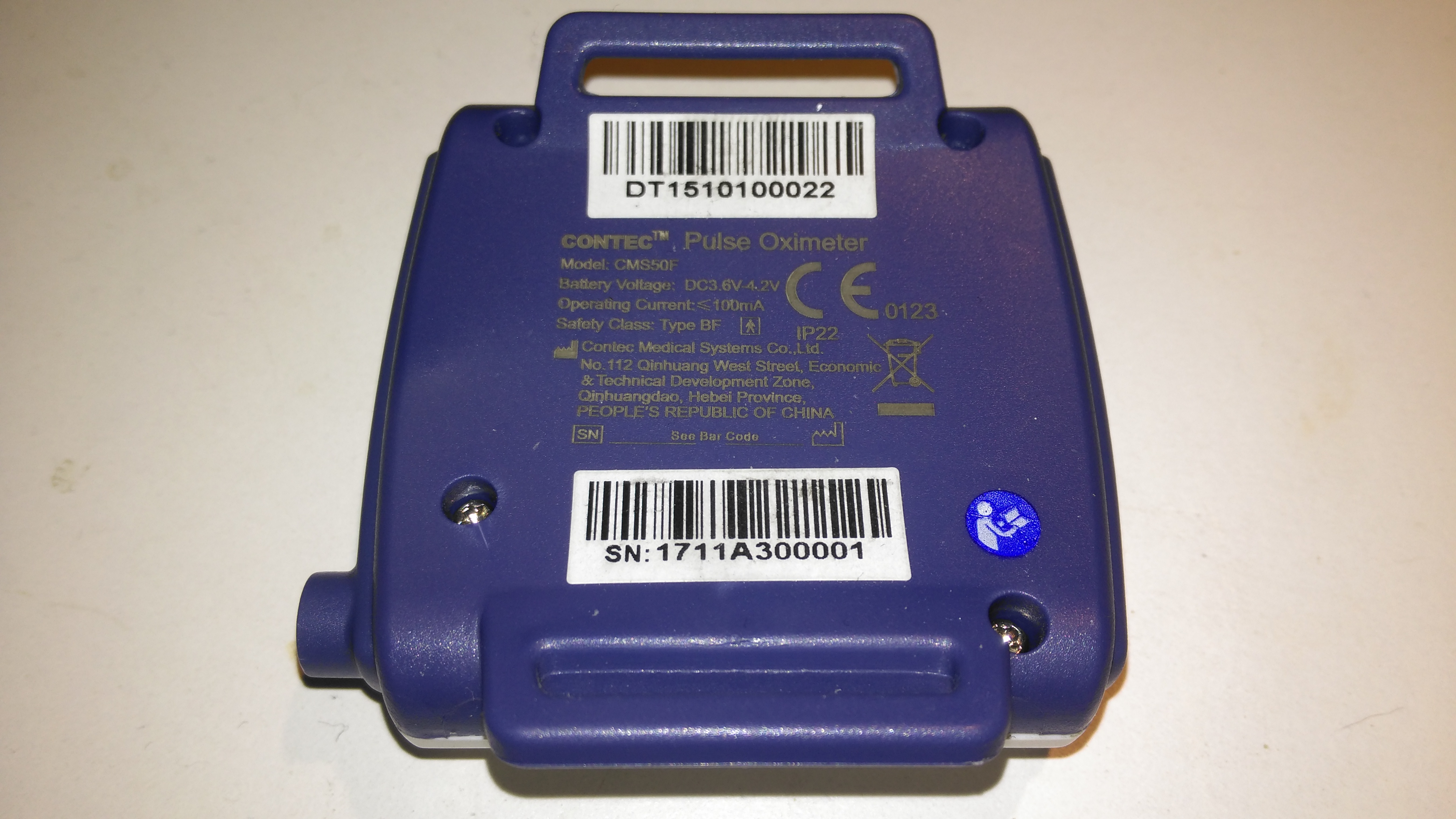
The rear has the specifications, laser-marked into the plastic. The serial numbers are just sticky labels though, and will come off easily with use.
Contec CMS-50F
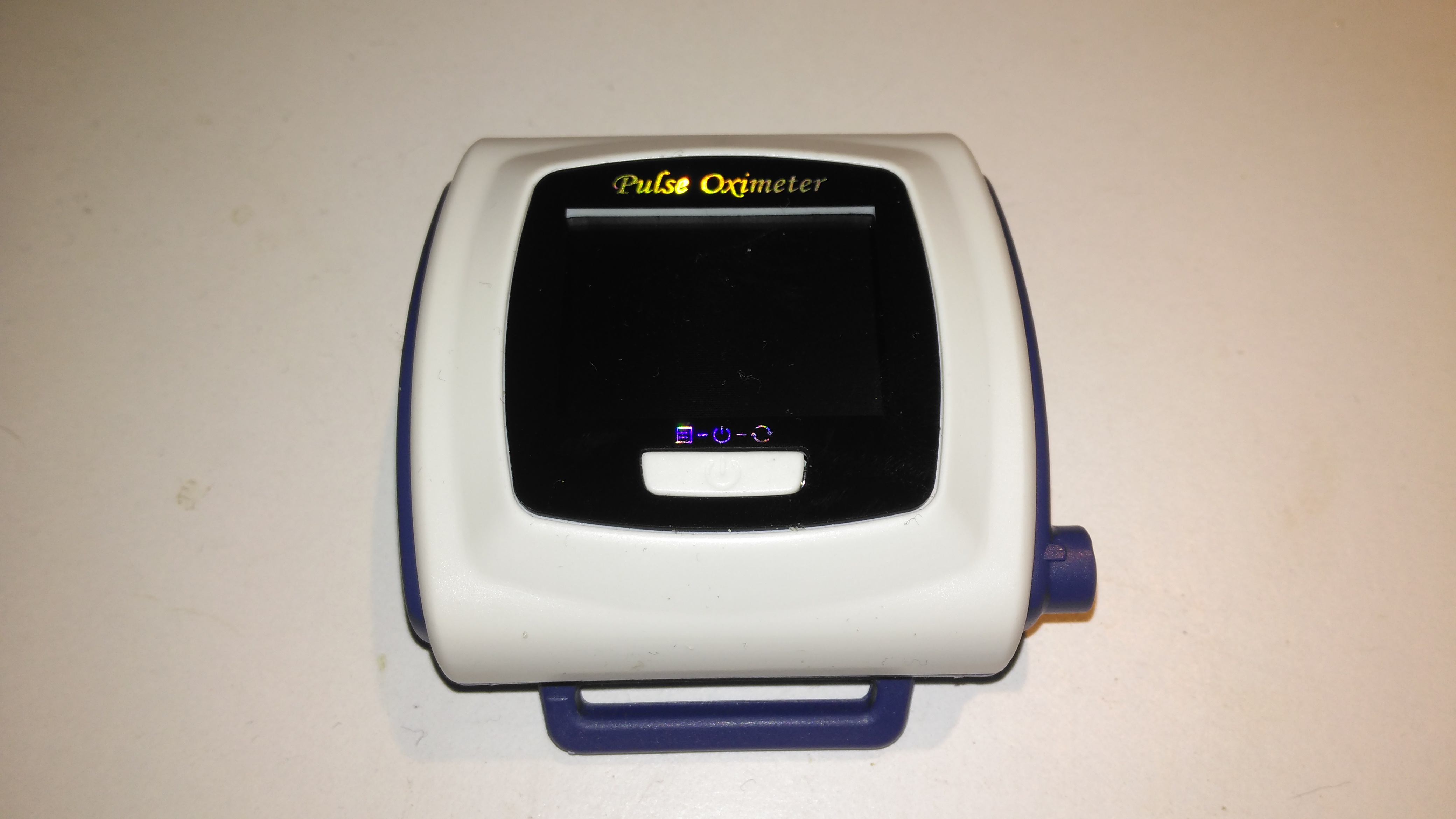
This is the Contec CMS-50F wrist-mounted pulse oximeter unit, which has the capability to record data continuously to onboard memory, to be read out at a later time via a USB-Serial link. There is software supplied with the unit for this purpose, although it suffers from the usual Chinese quality problems. The hardware of this unit is rather well made, the firmware has some niggles but is otherwise fully functional, however the PC software looks completely rushed, is of low quality & just has enough functionality to kind-of pass as usable.
Top Cover Removed
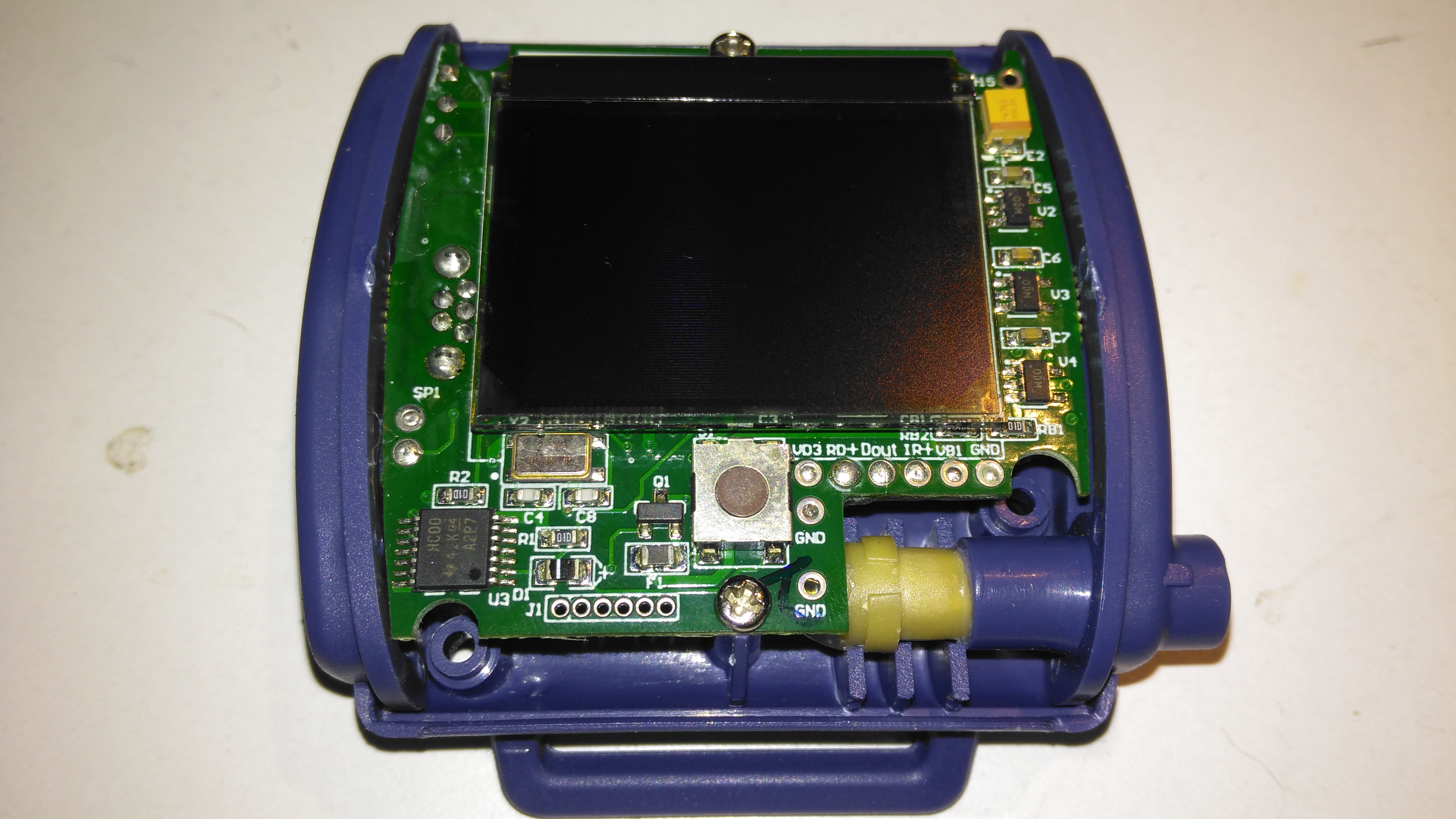
A total of 4 screws hold the casing together, once these are removed the top comes off. The large colour OLED display covers nearly all of the board here. The single button below is the user interface. The connection to the probe is made via the Lemo-style connector on the lower right.
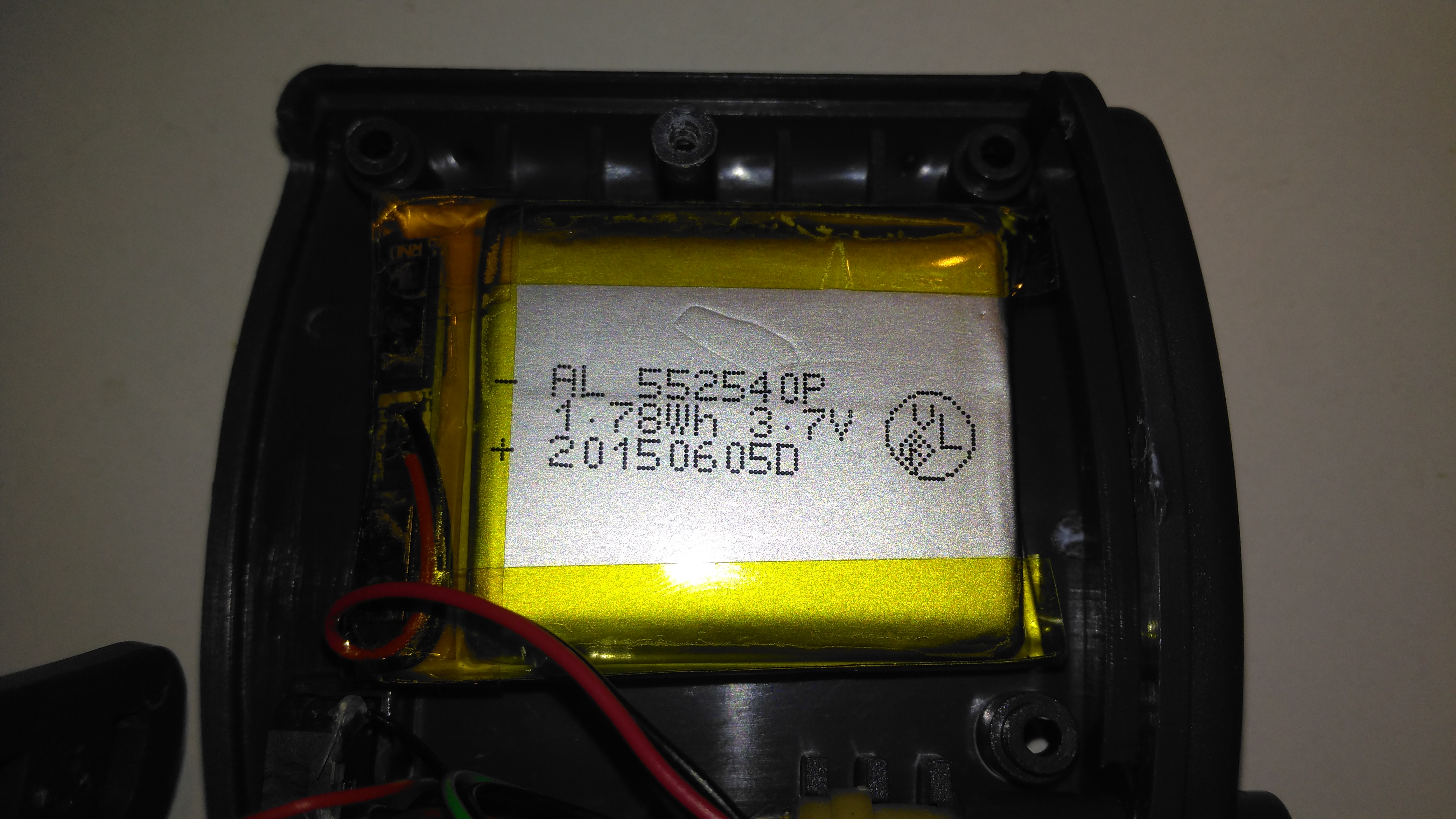
Lithium Cell
Power is provided by a relatively large lithium-ion cell, rated at 1.78Wh.
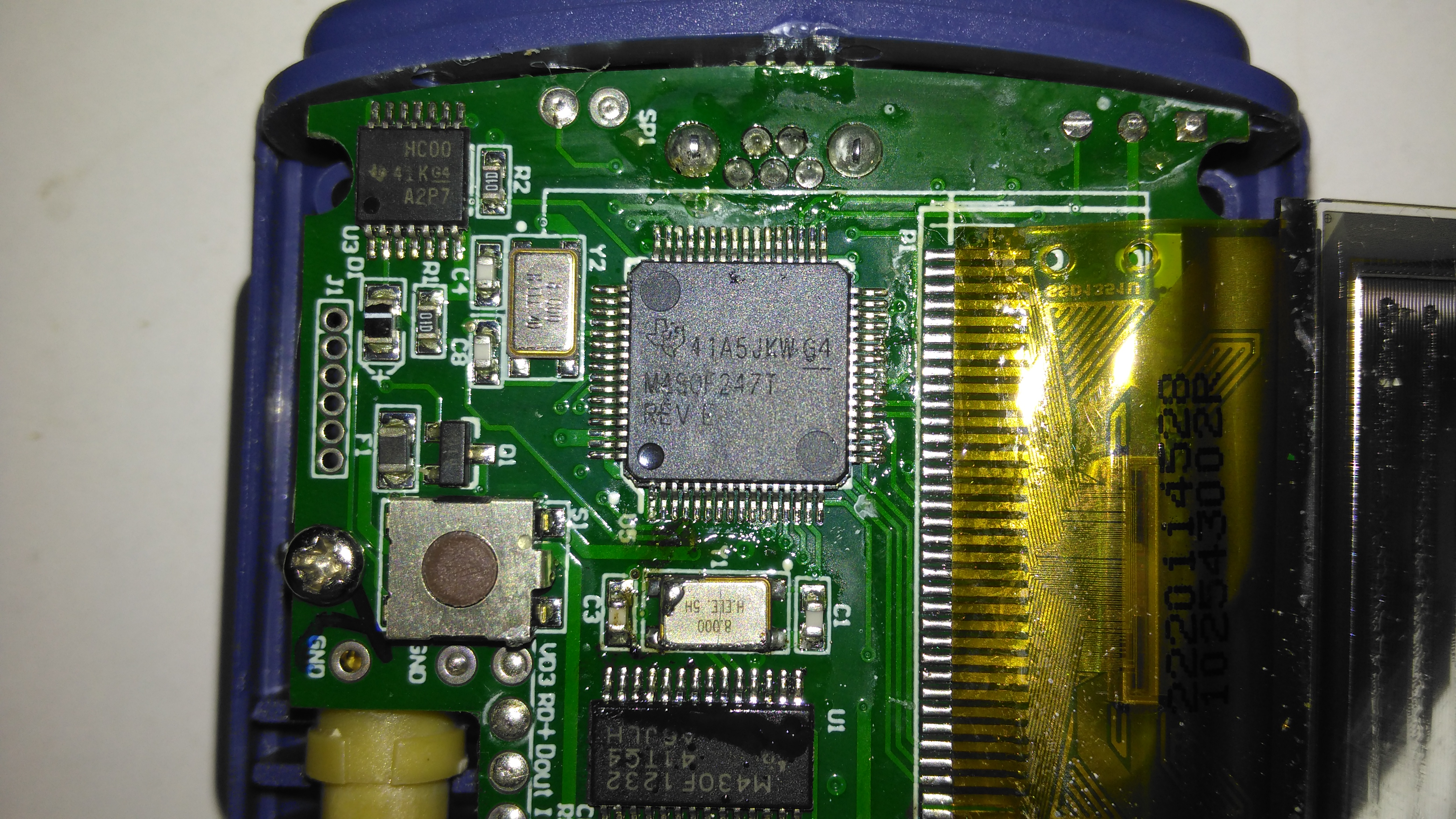
Main Processor
All the heavy lifting work of the LCD, serial comms, etc are handled by this large Texas Instruments microcontroller, a MSP430F247. The clock crystal is just to the left, with the programming pins. I’m not sure of the purpose of the small IC in the top left corner, I couldn’t find any reference to the markings.
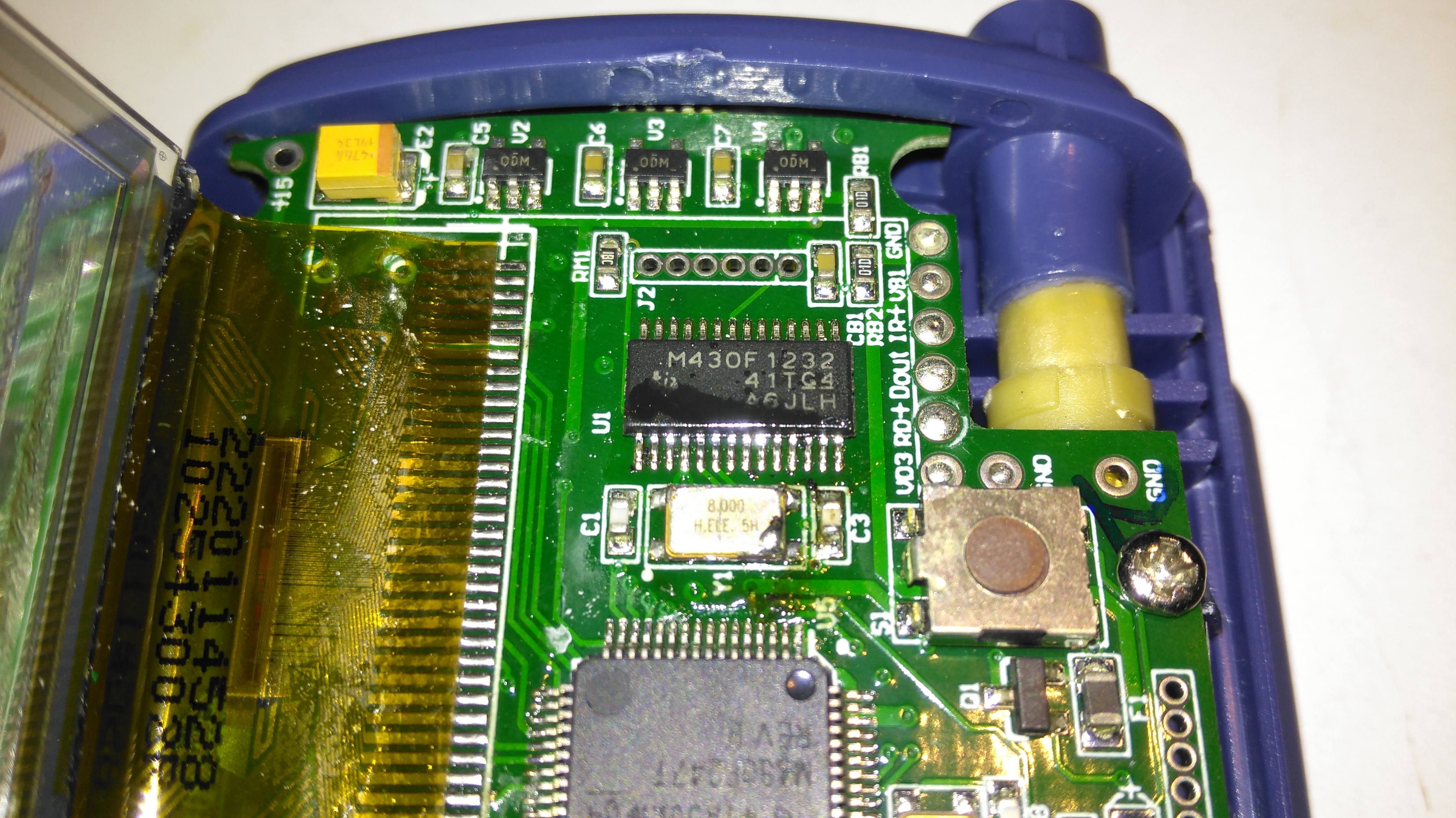
Aux Processor
The actual pulse oximetry sensor readings seem to be dealth with by a secondary microcontroller, a Texas Instruments M430F1232 Mixed-Signal micro. This has it’s own clock crystal just underneath. The connections to the probe socket are to the right of this µC, while the programming bus is broken out to vias just above. The final devices on this side of the board are 3 linear regulators, supplying the rails to run all the logic in this device.
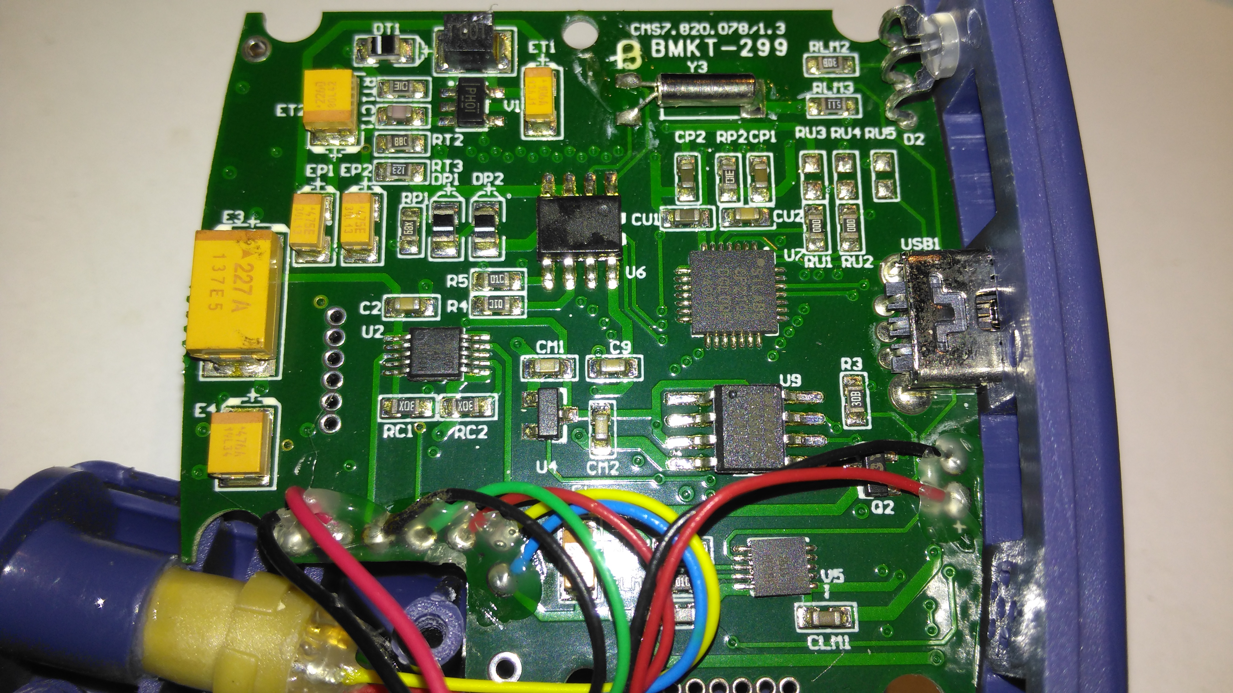
Main PCB Rear
The rear of the PCB has the SiLabs CL2102 USB-Serial interface IC, the large Winbond 25X40CLNIG 512KByte SPI flash for recording oximetry data, and some of the power support components. The RTC crystal is also located here at the top of the board. Up in the top left corner is a Texas Instruments TPS61041 Boost converter, with it’s associated components. This is probably supplying the main voltage for the OLED display module.
For accurate measurements, you’ll need an optical instrument such as a monochromator or spectrophotometer or optical spectrum analyzer. But to simply see the complexity of the discharge spectrum inside the bore of a He-Ne laser tube, it’s much easier and cheaper.
(Spectra for various elements and compounds can be easily found by searching the Web. The NIST Atomic Spectra Database has an applet which will generate a table or plot of more spectral lines than you could ever want.)
Instant Spectroscope for Viewing Lines in He-Ne Discharge
It is easy to look at the major visible lines. All it takes is a diffraction grating or prism. I made my instant spectroscope from the diffraction grating out of some sort of special effects glasses – found in a box of cereal, no less! – and a monocular (actually 1/2 of a pair of binoculars).
If you missed the Kellogg’s option, diffraction gratings can be purchased from places like Edmund Scientific. You don’t need anything fancy – any of the inexpensive ‘transmission replica gratings’ on a flat rigid substrate or mounted between a pair of plane glass plates will be fine. In a pinch, a CD disc or other optical media will work but only as a reflection grating so mounting may be a problem. A spectroscope can also be made with a prism of course but a diffraction grating is likely to be less expensive and better for this application since it is much lighter and easier to mount.
The plasma tube of a bare He-Ne laser is an ideal light source since it provides its own slit as the glow discharge is confined to the long narrow capillary bore. However, this approach can also be used with other lasers as long as the beam can be focused to a spot on a wall or screen. This will produce a ‘bright spot spectra’ instead of politically correct lines but you can’t have everything. 🙂
The diffraction grating can be used by itself but the additional optics will provide magnification and other benefits for people with less than perfect eyeballs.
Glue the diffraction grating to a cardboard sleeve that can be slipped over the (or one) objective of a monocular, binocular, or small telescope – or the telephoto lens of your camera. Orient it so that the dispersion will be vertical (since your slit will be horizontal).
Operate the HeNe tube on a piece of black velvet or paper. This will result in optimum contrast. This is best done in a darkened room where the only source of light is the laser tube itself. Just don’t trip and zap yourself on the high voltage!
A diffraction grating produces several images. The zero’th order will be the original image seen straight ahead. The important ones are the first order spectra. Tip the instrument up or down to see these. The dispersion direction – order of the colours – will depend on which way it is tipped.
Any distance beyond the closest focus of your instrument will work but being further away will reduce the effective width of the ‘slit’ resulting in the ability to distinguish more closely spaced lines.
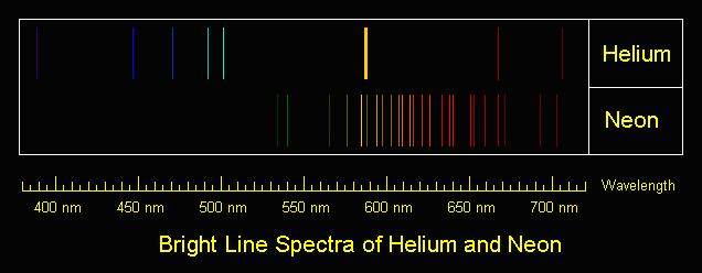
The shear number of individual spectral lines present in the discharge is quite amazing. You will see the major red, orange, yellow, and green lines as well as some far into the blue and violet portions of the spectrum and toward the IR as well.
Bright Line Spectra of Helium and Neon
All of those shown will be present as well as many others not produced by the individual gas discharges. There are numerous IR lines as well but, of course, these will not be visible.
Place a white card in the exit beam and note where the single red output line of the He-Ne tube falls relative to the position and intensity of the numerous red lines present in the gas discharge.
As an aside, you may also note a weak blue/green haze surrounding the intense main red beam (not even with the spectroscope). This is due to the blue/green (incoherent) spectral lines in the discharge being able to pass through the output mirror which has been optimized to reflect well (>99 percent) at 632.8 nm and is relatively transparent at wavelengths some distance away from these (shorter and longer but you would need an IR sensor to see the longer ones). Since it is not part of the lasing process, this light diverges rapidly and is therefore only visible close to the tube’s output mirror.
Dynamic Measurement of Discharge Spectra
The following is trivial to do if you have a recording spectrometer and external mirror He-Ne laser. For an internal mirror He-Ne laser tube, it should be possible to rock one of the mirrors far enough to kill lasing without permanently changing alignment. If you don’t have proper measuring instruments, don’t worry, this is probably in the “Gee wiz, that’s neat but of marginal practical use” department. 🙂
(From: George Werner (glwerner@sprynet.com).)
Here is an effect I found many years ago and I don’t know if anyone has pursued it further.
We had a recording spectrometer in our lab which we used to examine the incoherent light coming from the laser discharge. This spectrum when lasing was slightly different from the spectrum when not lasing, which one can expect since energy levels are redistributed. As with most detectors, ours used a chopper in the spectrometer light beam and a lock-in amplifier.
Instead of putting the chopper in the path of light going to the spectrometer, I put it in the path of the internal laser beam, so that instead of an open/closed signal going to the amplifier it was a lasing/not-lasing signal. What was recorded then was three kinds of spectrum lines: some deflected positive in the normal way, others deflected negative, and the third group were those that were unaffected by chopping, in which case when we passed over the line we only saw an increase in the noise level. Setting up such a test is easy. The hard part is interpreting the data in a meaningful way.
Other Colour Lines in Red He-Ne Laser Output
When viewing spectral lines in the actual beam of a red He-Ne laser, you may notice some very faint ones far removed from the dominant 632.8 nm line we all know and love. (This, of course, also applies to other colour He-Ne lasers.)
For He-Ne lasers, the primary line (usually 632.8 nm) is extremely narrow and effectively a singularity given any instrumentation you are likely to have at your disposal. Any other lines you detect in the output are almost certainly from two possible sources but neither is actual laser emission:
Plasma discharge – there are many strong emission lines in the actual discharge – and none of them are actually at the 632.8nm lasing wavelength! These extend from the mid-IR through the violet.Close to the output mirror, you may see some of this light seeping through especially at wavelengths in the green, blue, and violet, for which the dielectric mirrors are nearly perfectly transparent. However, such light will be quite divergent and diffuse and won’t be visible at all more than a couple of inches from the mirror.
Superradiance – As we know, He-Ne lasers can be made to operate at a variety of wavelengths other than the common 632.8nm red. The physics for these is still applicable in a red He-Ne tube but the mirrors do not have the needed reflectivity at these other wavelengths and therefore the resonator gain is too low to support true laser action. However, stimulated emission can still take place in superradiance mode – one pass down the tube and out, exiting easily for the green wavelength in particular since the dielectric mirrors are quite transparent in that region of the spectrum.The result will be a weak green beam that can sometimes be observed with a spectroscope in a very dark room room. It isn’t really quite as coherent or monochromatic as the beam from a true green He-Ne laser and probably has much wider divergence but nonetheless may be present. It may be easier to see this by using your spectroscope to view the bright spot from the laser on a white card rather than by deflecting the beam and trying to locate the green dot off to one side.Note: I have not been able to detect this effect on the short He-Ne tubes I have checked.
Since the brightness of the discharge and superradiance output should be about the same from either mirror, using the non-output end (high reflector) should prove easier (assuming it isn’t painted over or otherwise covered) since the red beam exiting from this mirror will be much less intense and won’t obscure the weak green beam.
Note that argon and krypton ion lasers are often designed for multiline output where all colours are coherent and within an order of magnitude of being equal to each other in intensity or with a knob to select an individual wavelength. Anything like this is only rarely done with He-Ne lasers because it is very difficult (and expensive) due to the low gain of the non-red lines.
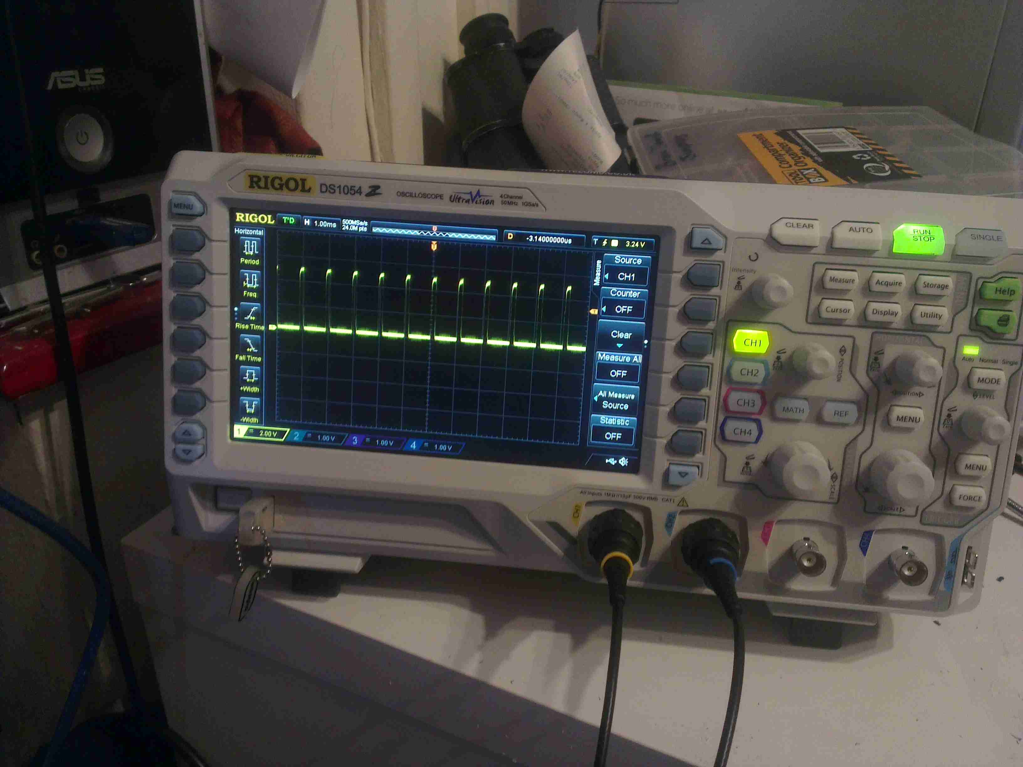
Alas, my old trusty Hameg HM303 30MHz oscilloscope has finally died. I’ve had this scope for many years, an eBay buy when I noticed they were going cheap.
It’s been replaced with a brand new Rigol DS1054Z, a 4-channel 50MHz DSO.
Scope
This is a big jump from the old analogue CRT scope I was using, it’s certainly going to be a steep learning curve!
System Info
I chose this scope through the help of the EEVBlog & it’s associated forums. Through this I discovered that I could upgrade the scope with a key to enable some extra features! In the above screenshot, the key has been applied, and the model number now shown is the DS1104Z.
This is the next scope up in the model chain, with many more triggering options, serial decoders, higher memory depth, recording & 100MHz bandwidth. While I rarely need to measure anything higher than in the kHz range, these options will definitely come in useful! The list of installed options is below:
Installed Options
And now for some sample waveforms, the scope has the option to save screenshots to USB flash disks, so when I make posts with waveforms in the future, the need to photo the screen of the scope is gone!
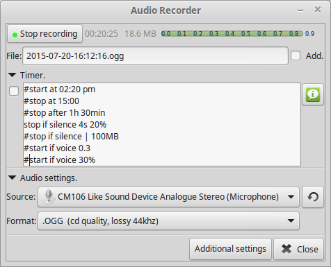
Since my new Wouxun has audio output jacks, I figured it would be useful to have the ability to record what my rig hears, if anything interesting comes on the air.
Under Linux, I use an application called, (creatively enough), Audio Recorder.
Recorder Screenshot
Using a simple connection to the mic input on a USB soundcard, I can capture everything the radio hears. Unfortunately this doesn’t work for outgoing audio, so it’s not much good at capture of my personal QSOs. For this I will have to set up another radio to act as the main receiver.
At some point in the future I will implement this with a Raspberry Pi as the audio capture server.
GB3MR currently has a big issue with a couple of pirates blocking use of the repeater, and while I’ve not heard anything from them in a few days, today has been much different.
I didn’t manage to get a full recording in this instance, but here’s some of the interference that’s being transmitted. In this case it sounds like there’s a licensed station or two trying to break through but not getting very far. (Sure I heard a callsign or two in there somewhere, whether they’re valid is another thing). Happy listening 🙂
Luckily it’s not difficult to obliterate the pirate signal when a valid QSO is in progress, and it’s not much of an inconvenience. They must be using a wet piece of string to get such a bad signal in 😉
Here’s another viewfinder CRT, removed from a 1980’s vintage VHS camera I managed to get cheap from eBay.
This unit is very similar to the last one I posted about, although there are a few small differences in the control circuitry.
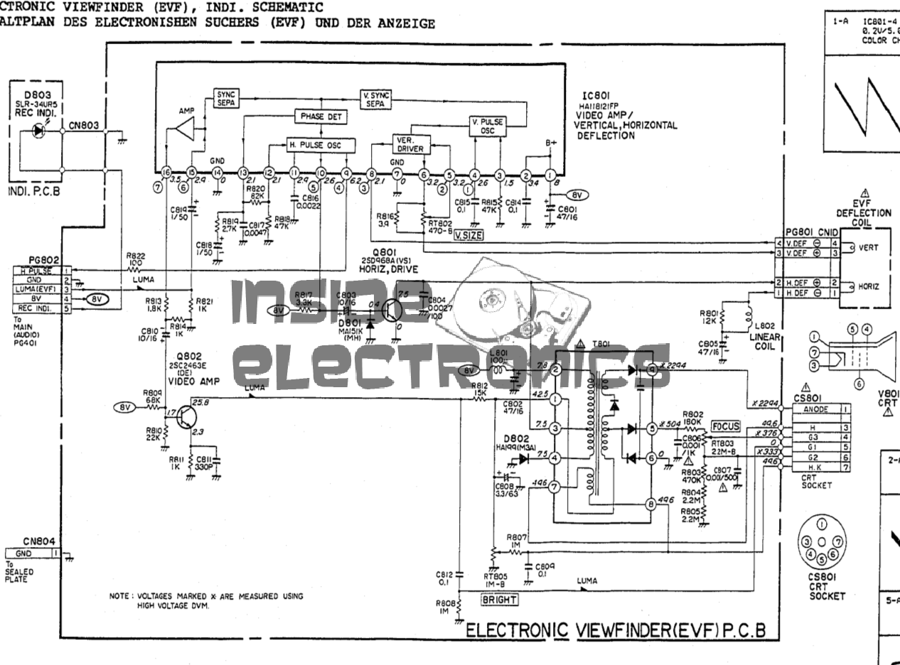
Viewfinder Schematic – Click to Embiggen
Here’s the schematic, showing all the functional blocks of the viewfinder circuitry. An integrated viewfinder IC is used, which generates all the required scan waveforms for the CRT.
On the left is the input connector, with the power & video signals. Only pins 2 (GND), 3 (Composite video), & 4 (+8v) are needed here. Pin 1 outputs a horizontal sync signal for use elsewhere in the camera, while pin 5 fed the recording indicator LED.
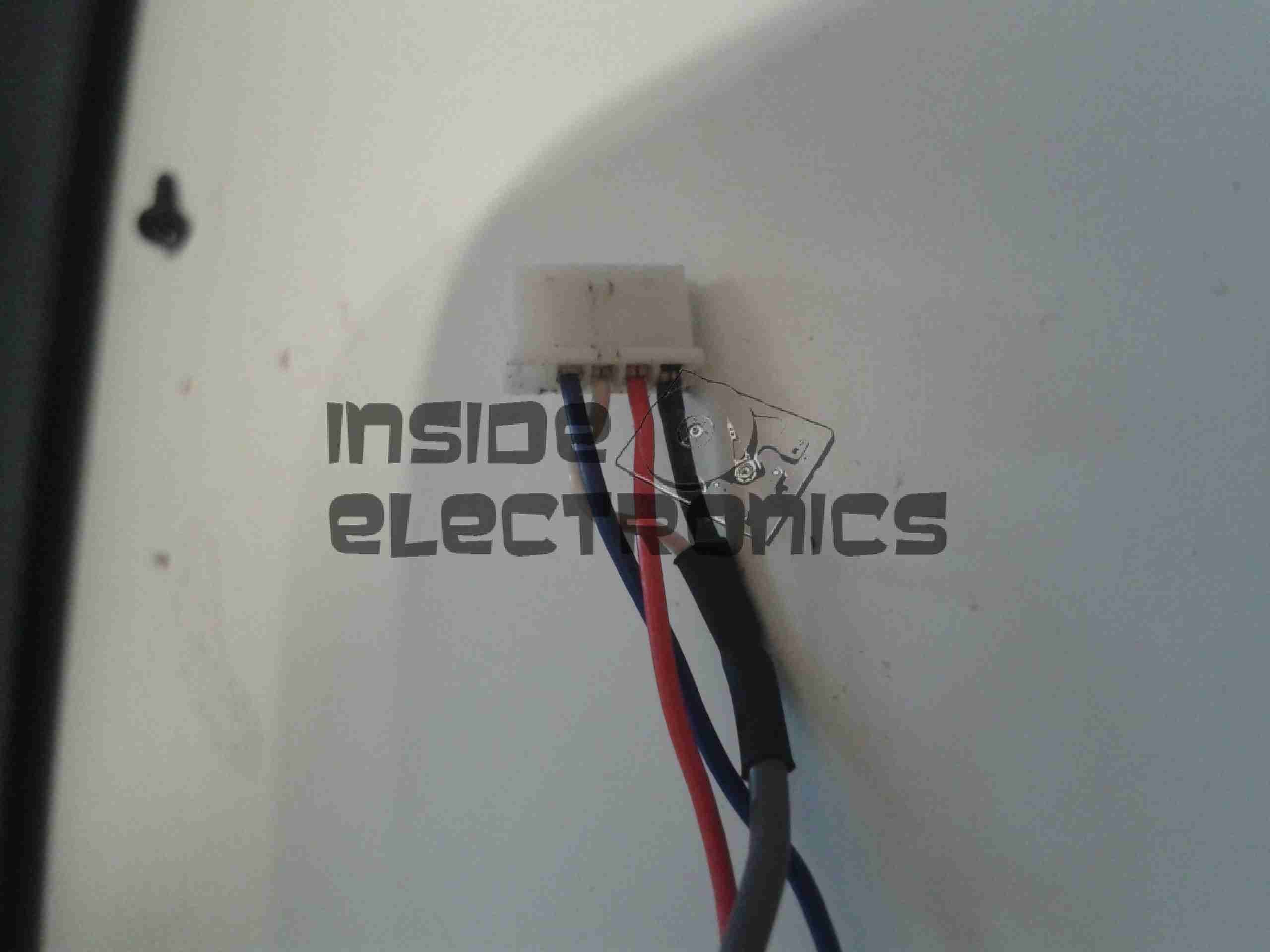
To make connection easier, I have rearranged the wires in the input connector to a more understandable colour scheme:
Input Connector
Red & Blue for power input, & a coax for the video. For the video GND connection, I have repurposed the Rec. LED input pin, putting a shorting link across where the LED would go to create a link to signal ground. Keeping this separate from the power GND connection reduces noise on the CRT.
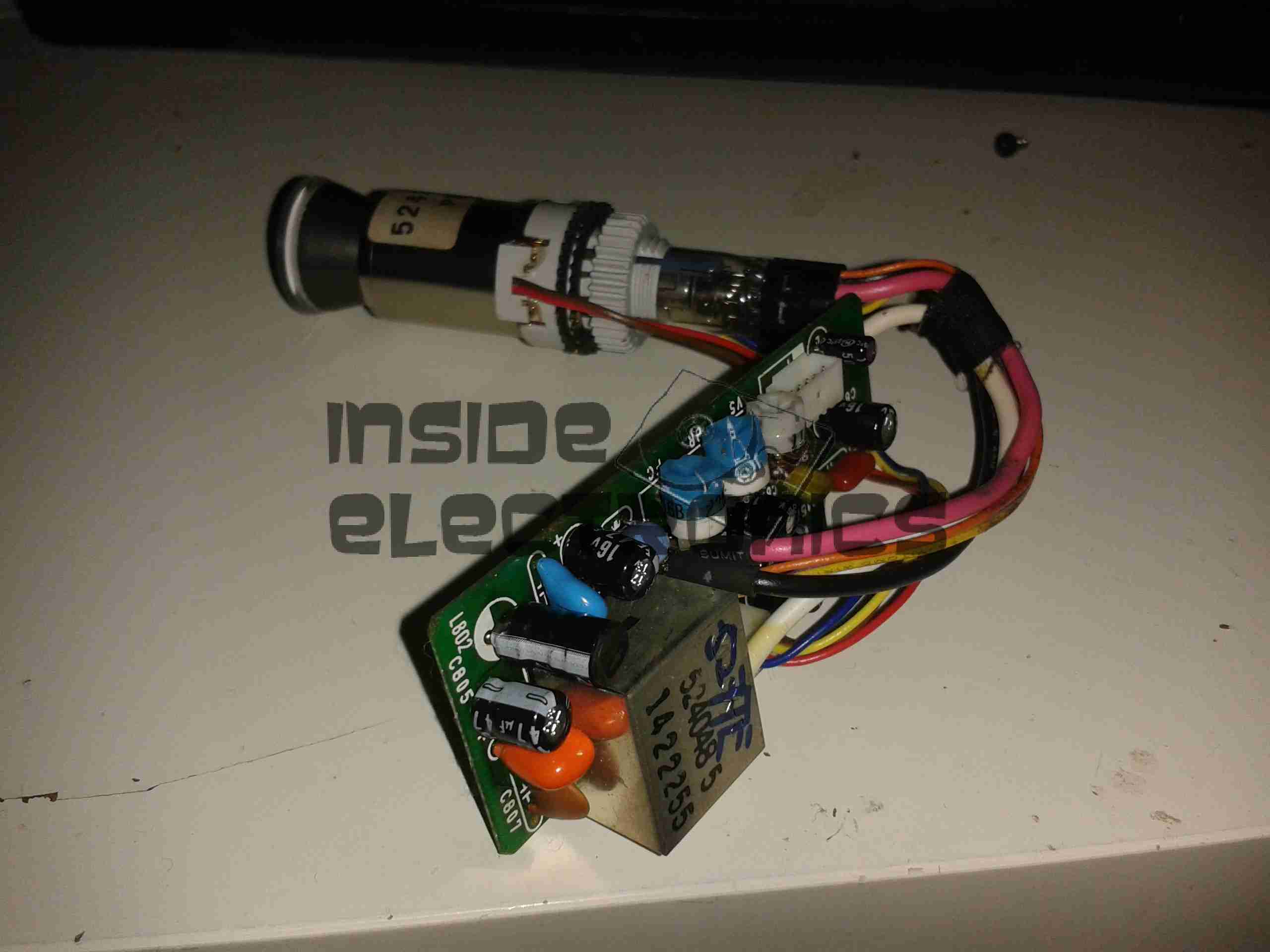
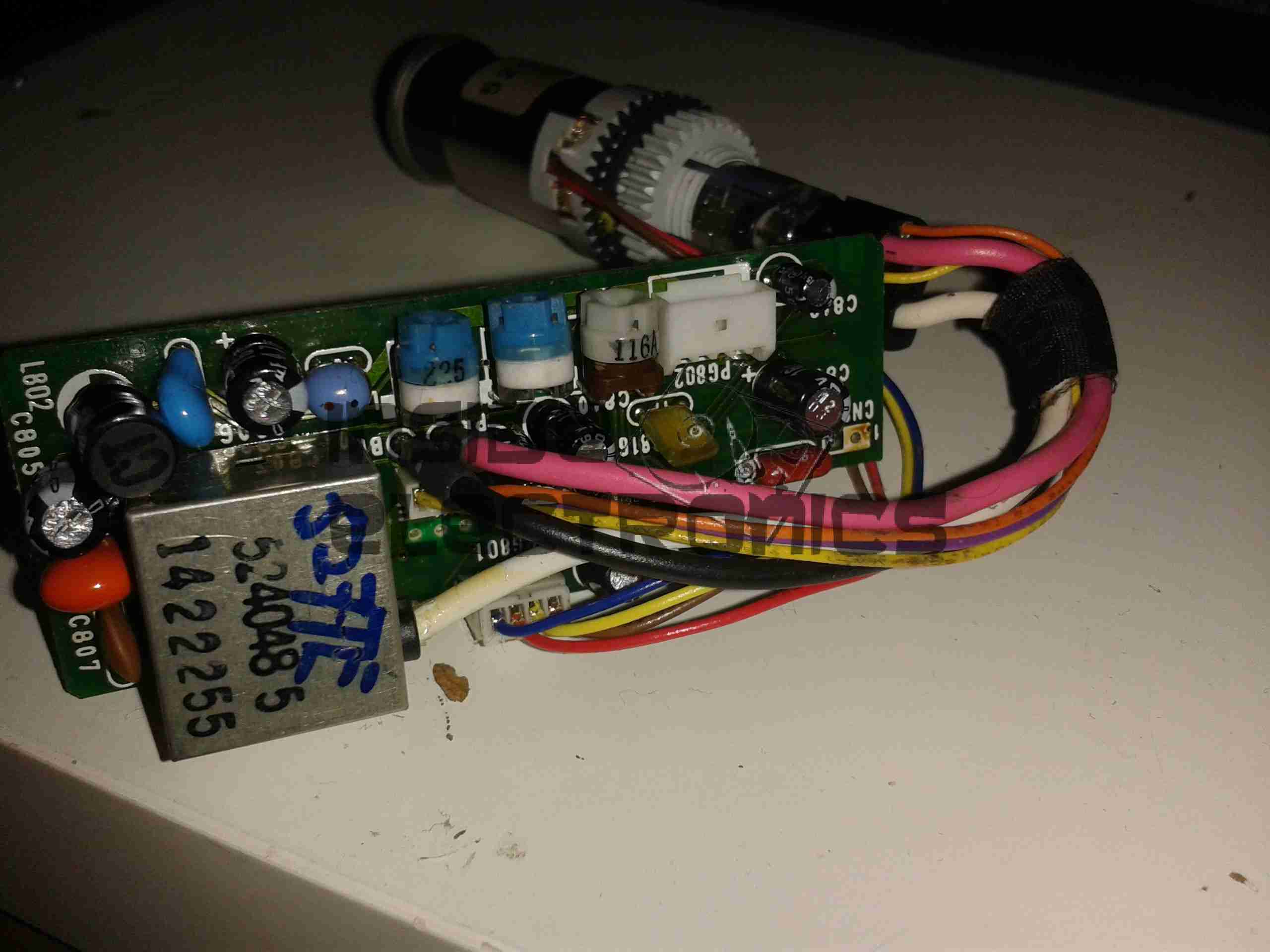
Viewfinder CRT Assembly
Here’s the complete assembly liberated from it’s plastic enclosure.
PCB Closeup
Closeup of the control PCB. The 3 potentiometers control the CRT brightness, focus & vertical size.
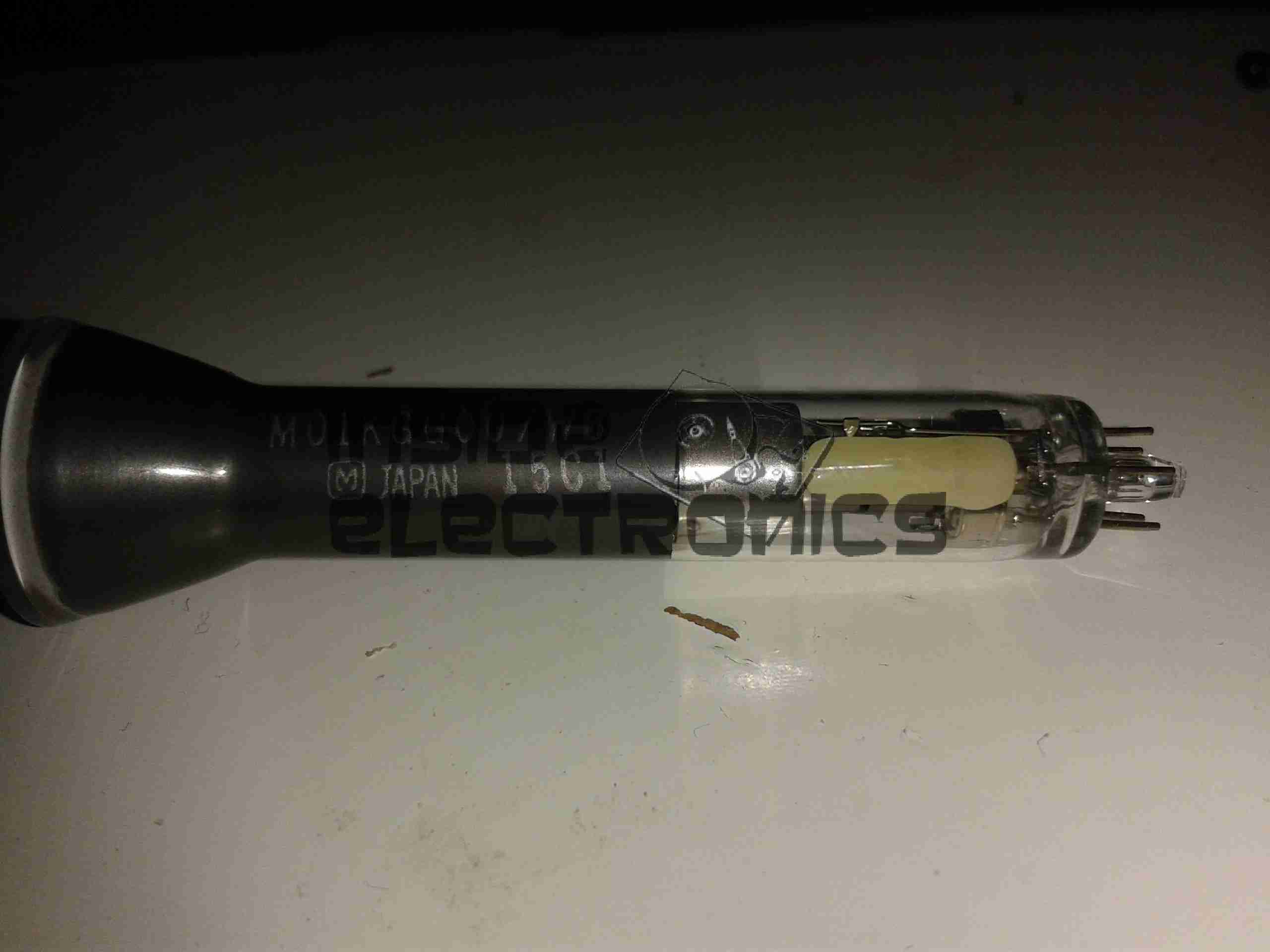
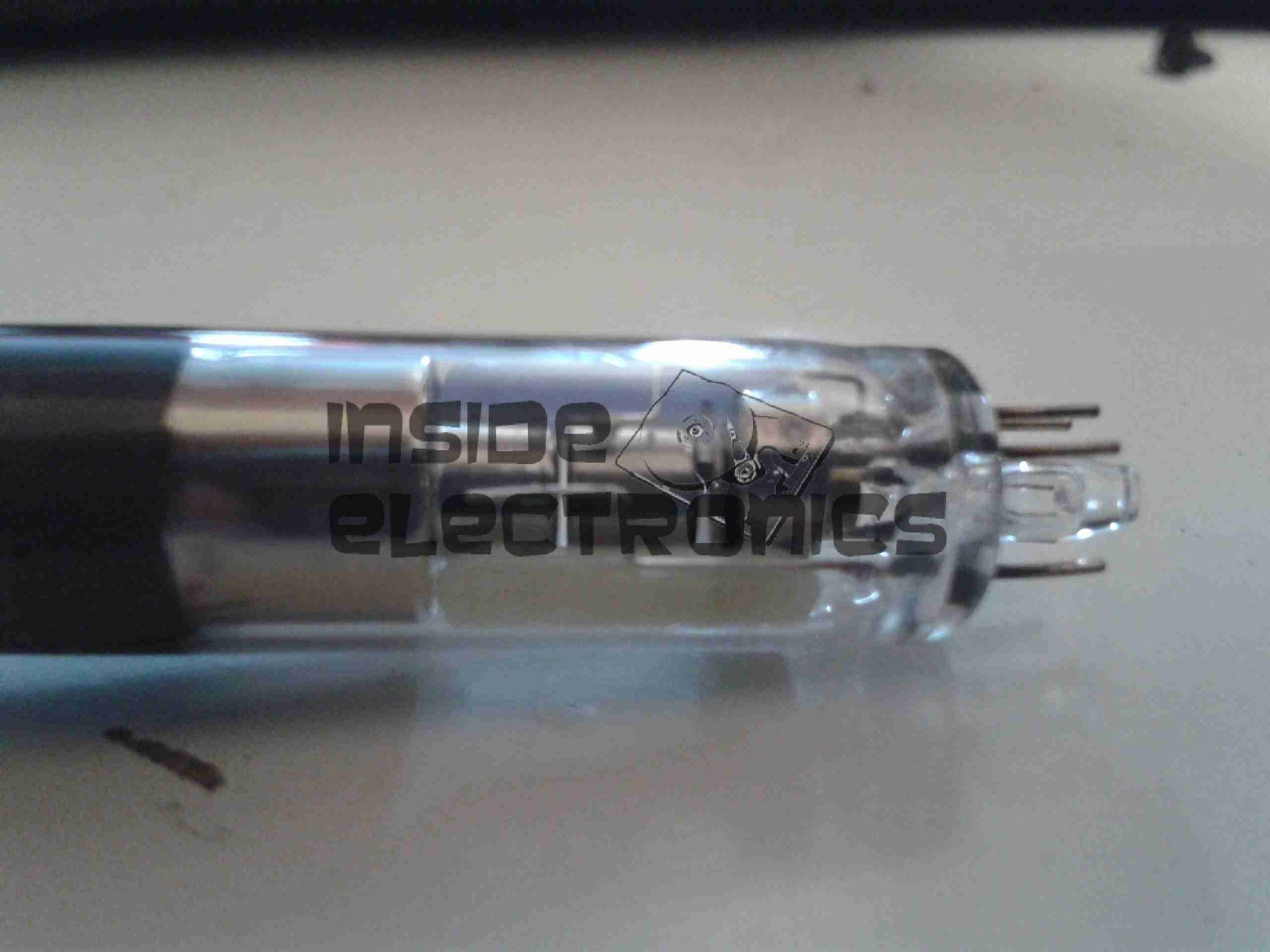
M01KGG007WB CRT
The tiny CRT. Only ~60mm in length, with an 18mm screen size. This tube runs on +2294v final anode voltage. Much higher than I expected.
Electron Gun Closeup
The electron gun assembly, with the cathode, focus & final anode cups.
Phosphor Screen
This screen is just a little bigger than a UK 5p piece! A marvel of precision engineering.
Here is a Sanyo tape recorder, with built in voice activation. Takes standard audio cassettes.
Here visible is the speaker on the left, microphone is on the right of the tape window. The tape counter is at the top.
Back Removed
Back cover removed from the unit, showing the PCB & the connections. The IC is the controller/amplifier.
PCB
Top of the PCB, control switches, volume potentiometer & microphone/headphone sockets on the right. DC power jack top left. Switch bottom centre senses what mode the tape drive is in.
Tape Deck
Rear of the tape deck, main drive motor is bottom right, driving the capstan through a drive belt. This drives the tape spools through a series of gears & clutches. Belt going to top left drives the tape counter.
Drive
Front of the tape drive. Read/write head is top centre. Blue head is bulk erase head used during recording.
Speaker
Main speaker. 8Ω 0.25W.
Counter
Simple mechanical tape counter.
Tip Jar
If you’ve found my content useful, please consider leaving a donation by clicking the Tip Jar below!
All collected funds go towards new content & the costs of keeping the server online.