IPL hair removal is rather similar to laser hair removal – high energy photons are directed into the hair follicle to heat the cells up until death occurs, stopping the hair from growing. These units use high-energy Xenon flash tubes to do the job, and operate in exactly the same fashion as a camera flash. Here are the internals of such a device.
Mainboard
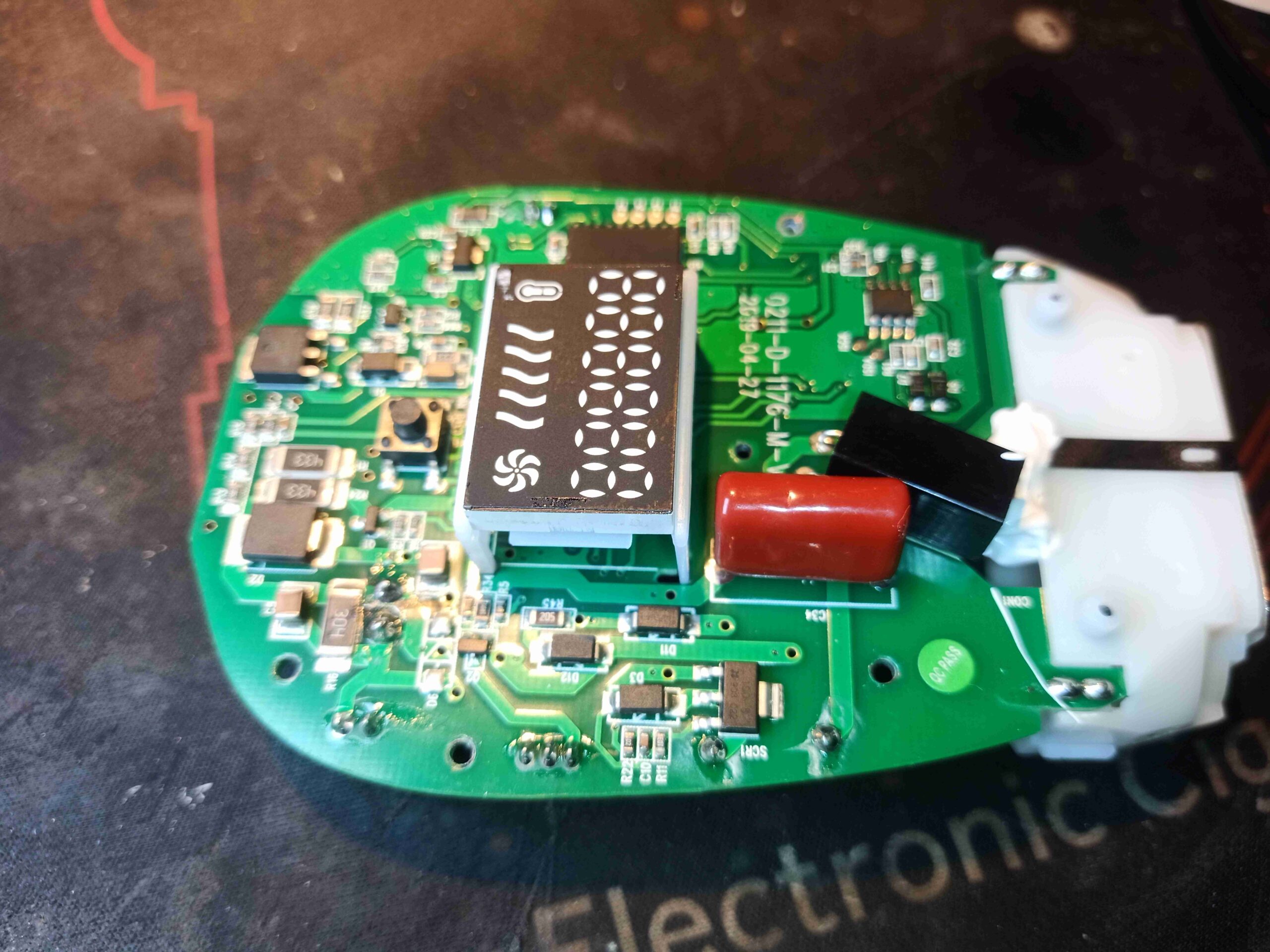
The mainboard in the top of the unit deals with all the functions of the device. There’s a main microcontroller, which in this case is an unmarked IC. The UI is a simple LED display, showing the number of shots on the tube remaining. These units come with 500,000 shots programmed in. The limit is to prevent the Xenon tube from exploding when it reaches end of life. In the case of these devices, after the counter reaches zero, the unit is disposed of. The trigger transformer is visible at the right of the board, along with it’s capacitor. This is triggered by a small Thyristor at the bottom edge of the board just to the right of the LED display. There are some power handling components on the left side, along with the main switching FET & gate drive IC for the high voltage supply.
There are several power settings, and the power itself is varied by the voltage on the main capacitor, from around 270v to 400v. There’s no dedicated switching IC here – The microcontroller generates a 65kHz square wave, from 0-50% duty cycle to drive the main switching FET. There’s a resistive feedback network to regulate the boost converter’s output voltage.
Mainboard Bottom
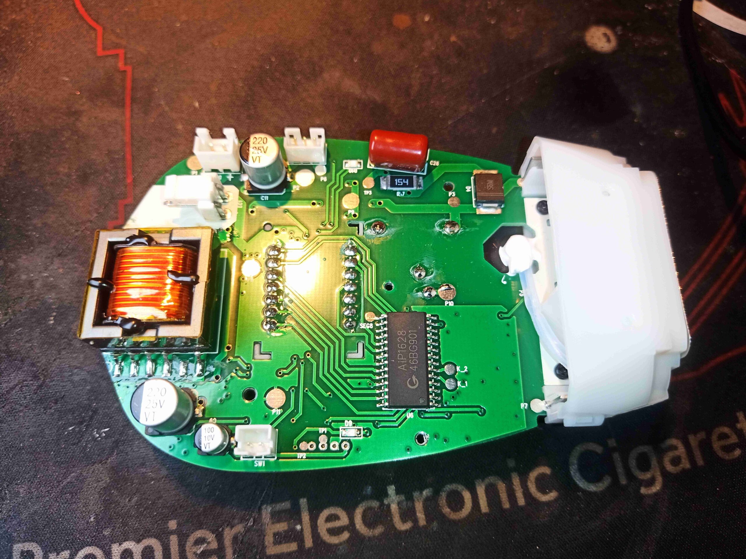
There’s less on the bottom of the PCB, apart from the connections to the PSU, cooling fan, capacitor & trigger button, there is the transformer for the HV supply. At the lower centre, is the driver IC for the LED display.
Flashtube
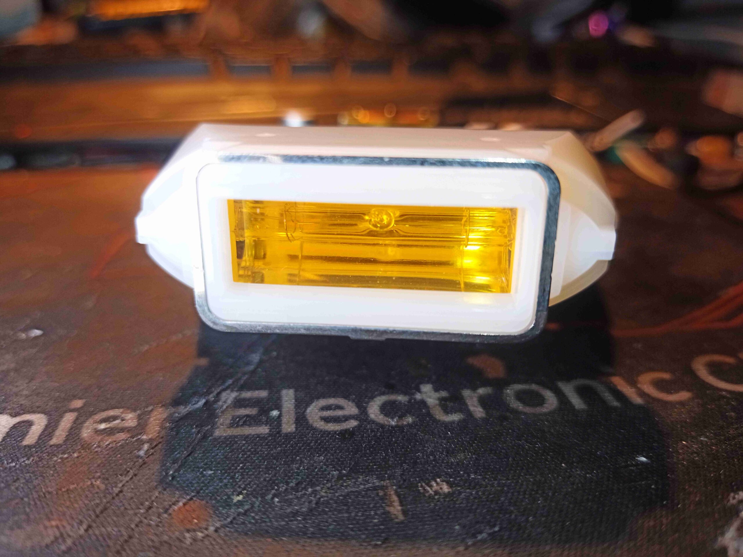
The flash tube is mostly hidden inside a plastic shroud with an amber filter glass on the front to provide the correct light spectrum. The metal ring around the outside edge is part of a capacitive detection mechanism that prevents the tube firing unless it’s placed against skin. I have no doubt that the intensity of light from these devices could quite easily cause eye damage. Even absorbing the energy into the skin is slightly painful – hitting black tattoo ink with it feels like a needle prick!
Cooling Blower
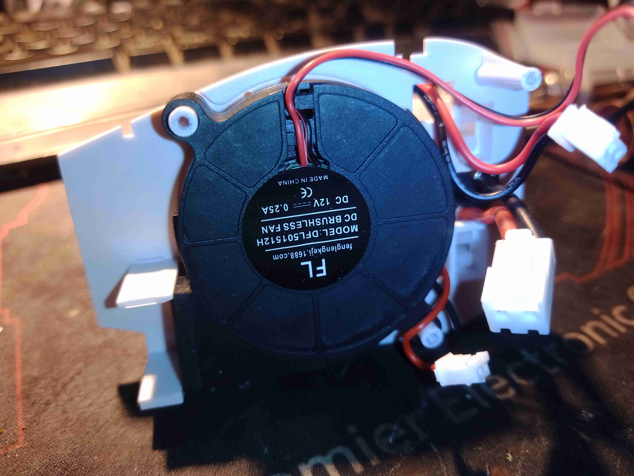
Since the flash tube passes such a large pulse of energy, it is force cooled by this small blower which sits under the mainboard, and directs air into a slot in one end of the tube housing. The other end allows the air to exhaust back out, taking the heat with it. This fan runs continually while the device is powered on. This fan shifts an impressive amount of air for it’s size.
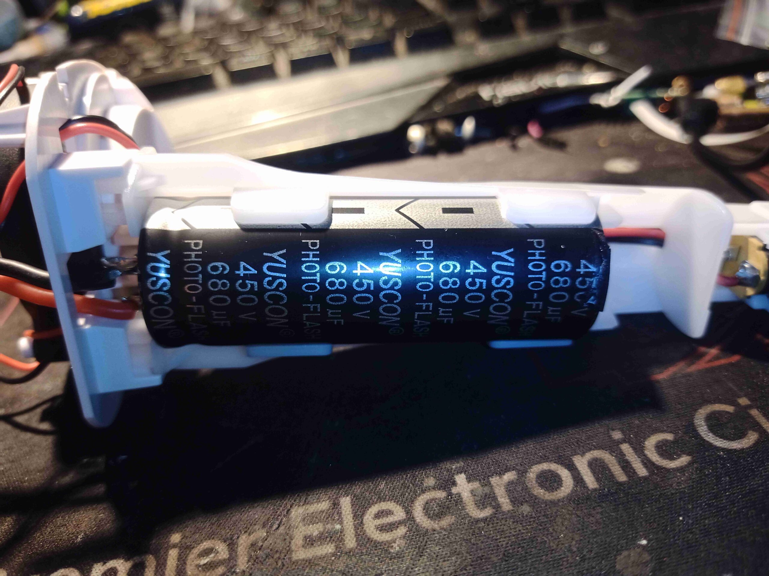
Flash Capacitor
Finally, there is the main storage capacitor for the flash tube. This sits down in the handle, and is massive at 450v 680µF, providing 69 Joules of energy at full charge. In the case of this unit, the energy is variable from 25-55J.
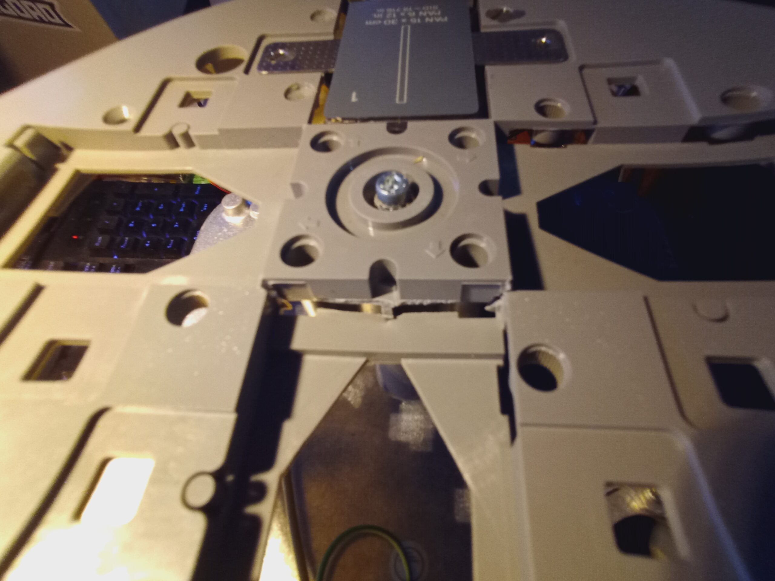
On the front of the head is the filter carousel. In this case it’s only fitted with a 2.5mm Aluminium filter. These are used to filter out the low-energy X-Rays from the beam, reducing the overall dose to the patient of radiation that does not contribute to the resulting image, as these lower energy rays are totally absorbed.
Top Cover Removed
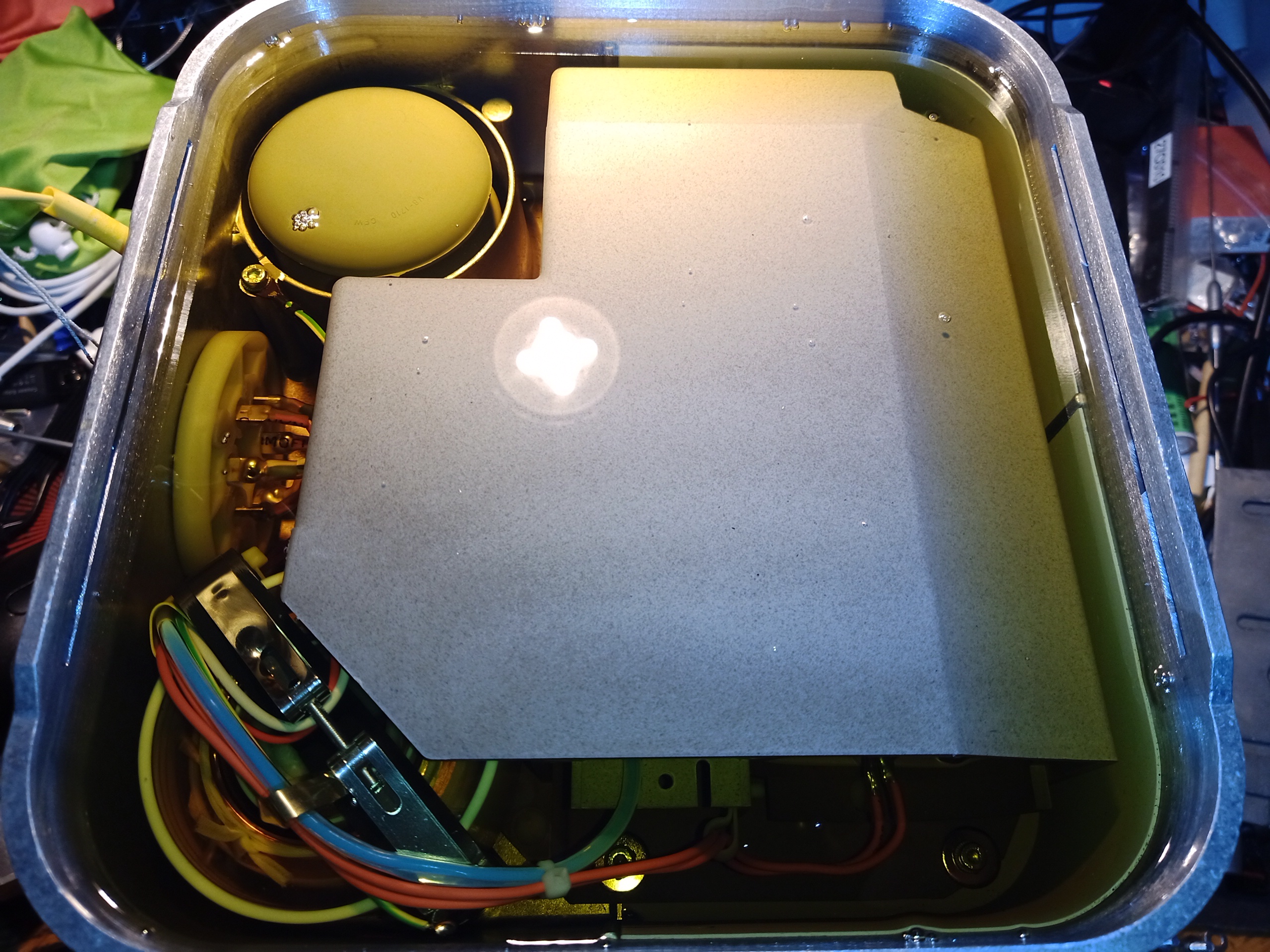
Removing a lot of cap screws later & the O-Ring sealed cover comes off the head. Unsurprisingly, this is full of dielectric mineral oil for insulation & cooling. There’s not much to see yet, as most of the components are hidden inside the plastic housings. The expansion bellows is at the top left, and the main HV transformer bottom left.
Wiring Feedthrough
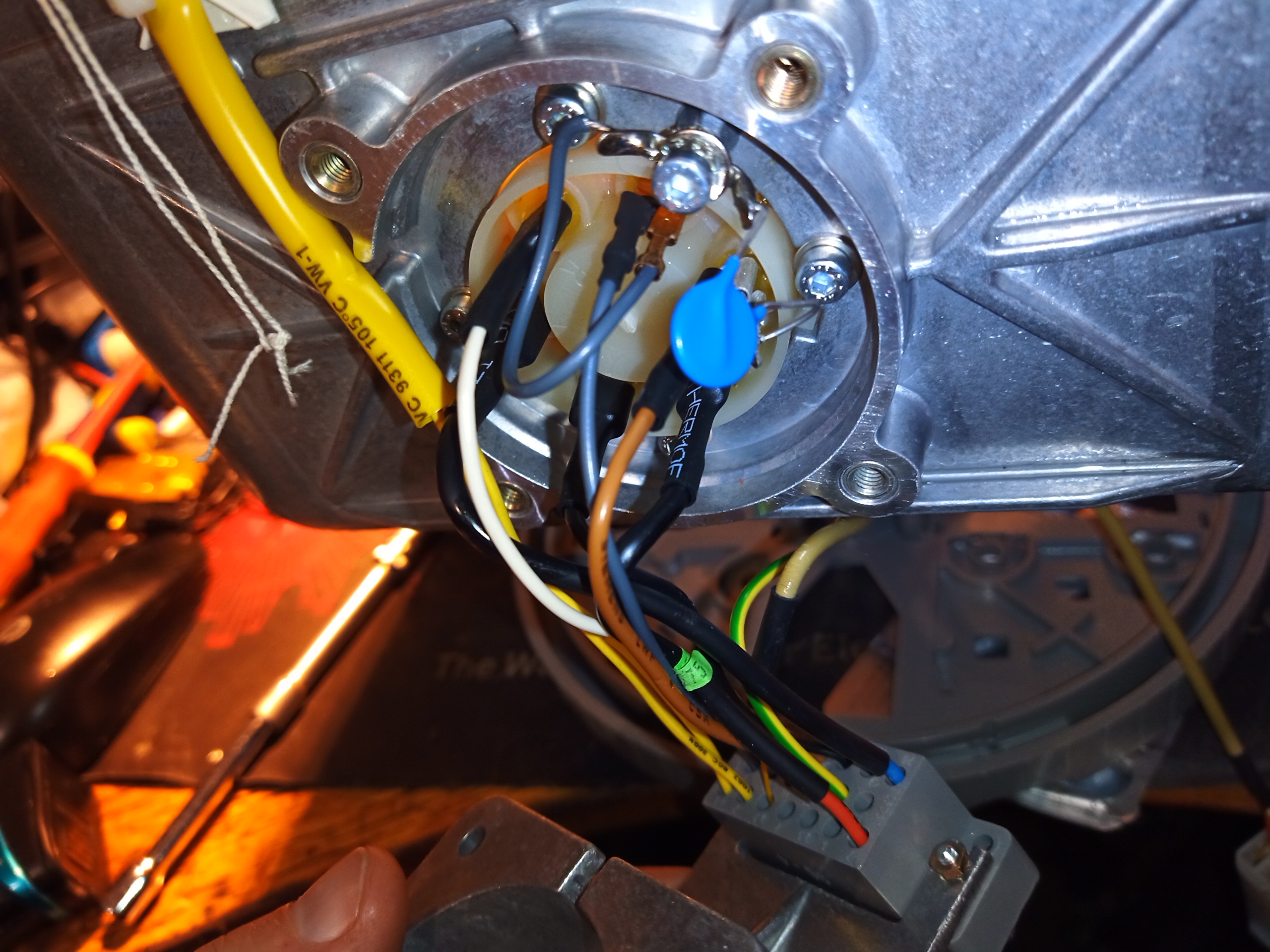
All the wiring to the head is fed through this plastic plug in the side, which is O-Ring sealed into the casting to prevent oil leaking out.
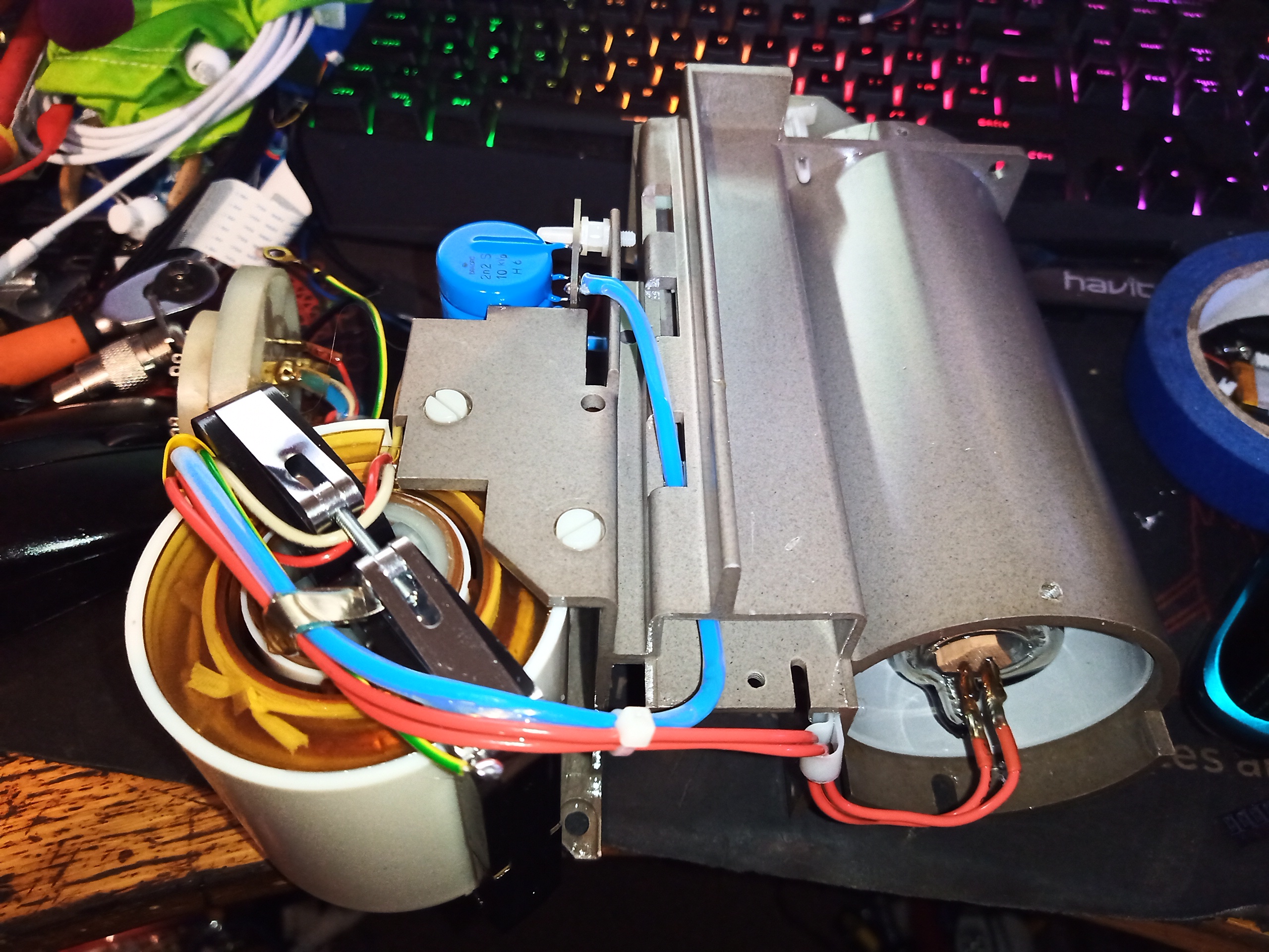
Tube Assembly
A clean bottle, syringe & some oily mess later, I manage to get the core out of the housing. This unit had about 3L of oil! The main HV transformer is hanging off the lower left corner of the plastic frame here, with the rest of the PSU behind it. The X-Ray tube is hiding within a metal shield in the tube to the right. There are no primary drive components present in the head – all of that is in the rest of the X-Ray machine.
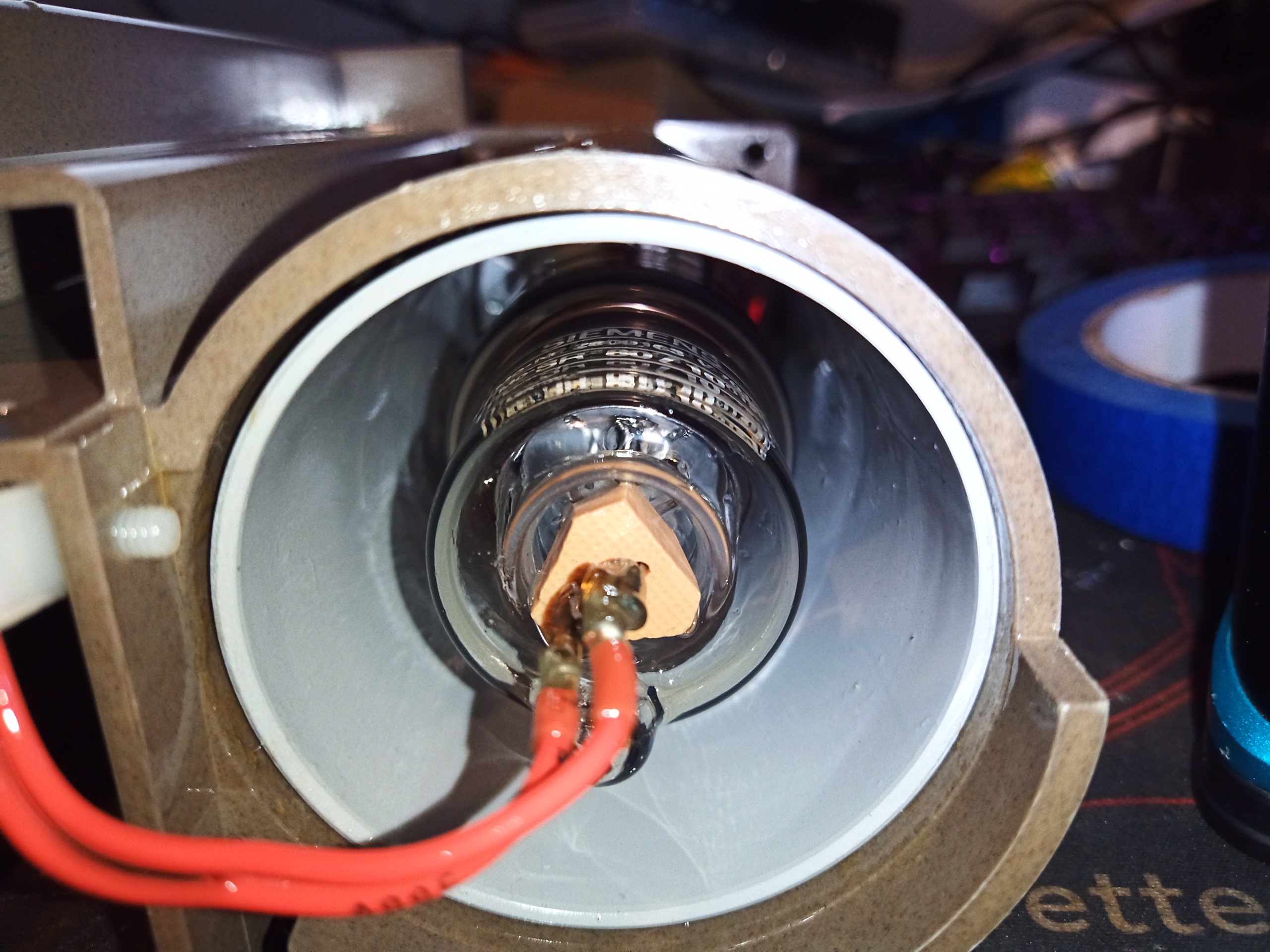
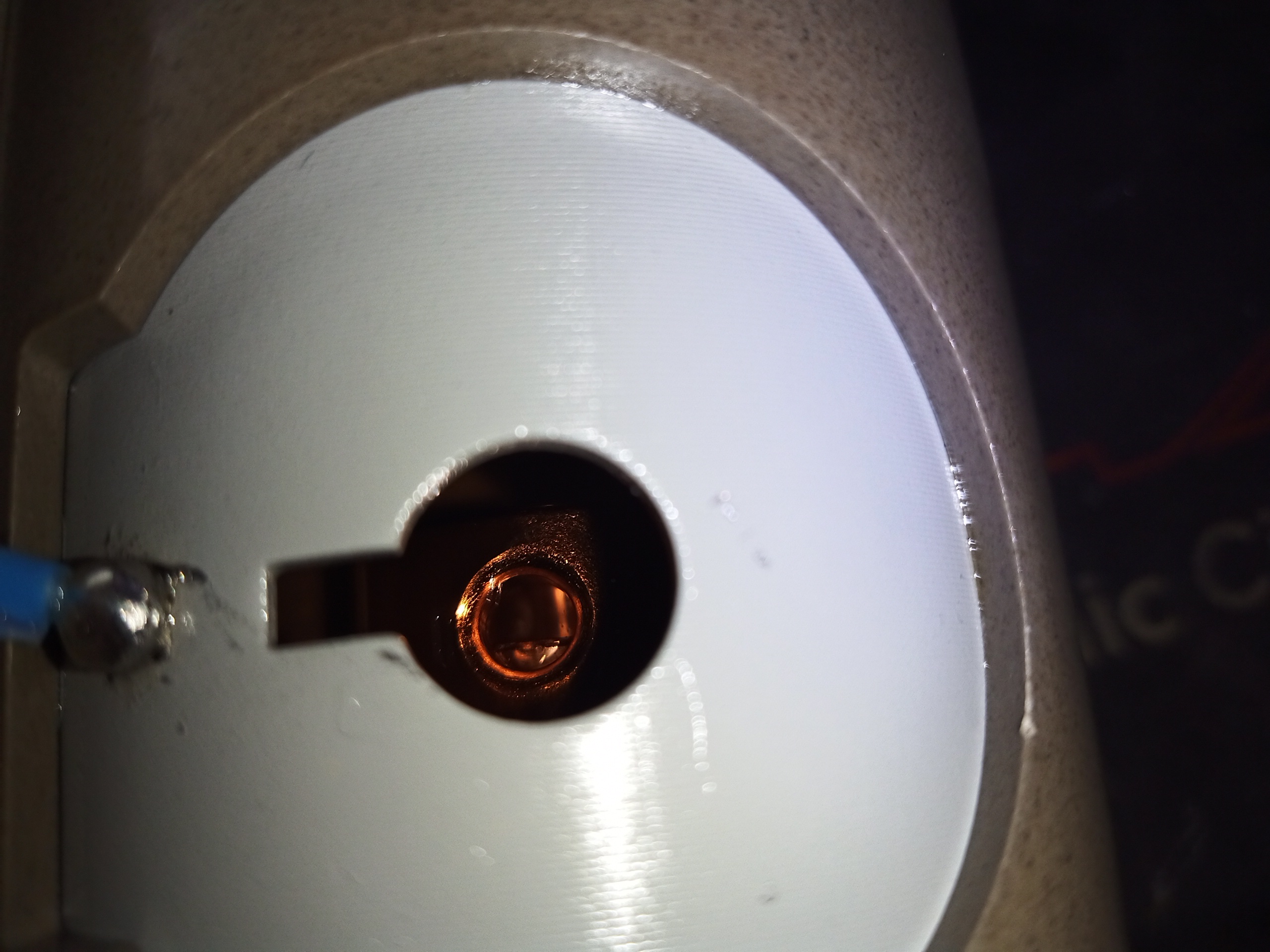
X-Ray Tube Sleeve
A look down filament end of the X-Ray tube. There’s a shield around this, likely to help stop stray X-Rays, and to provide some electric field strength distribution, as this is connected to centre of the HV PSU’s voltage multiplier, biasing it at around +40kV.
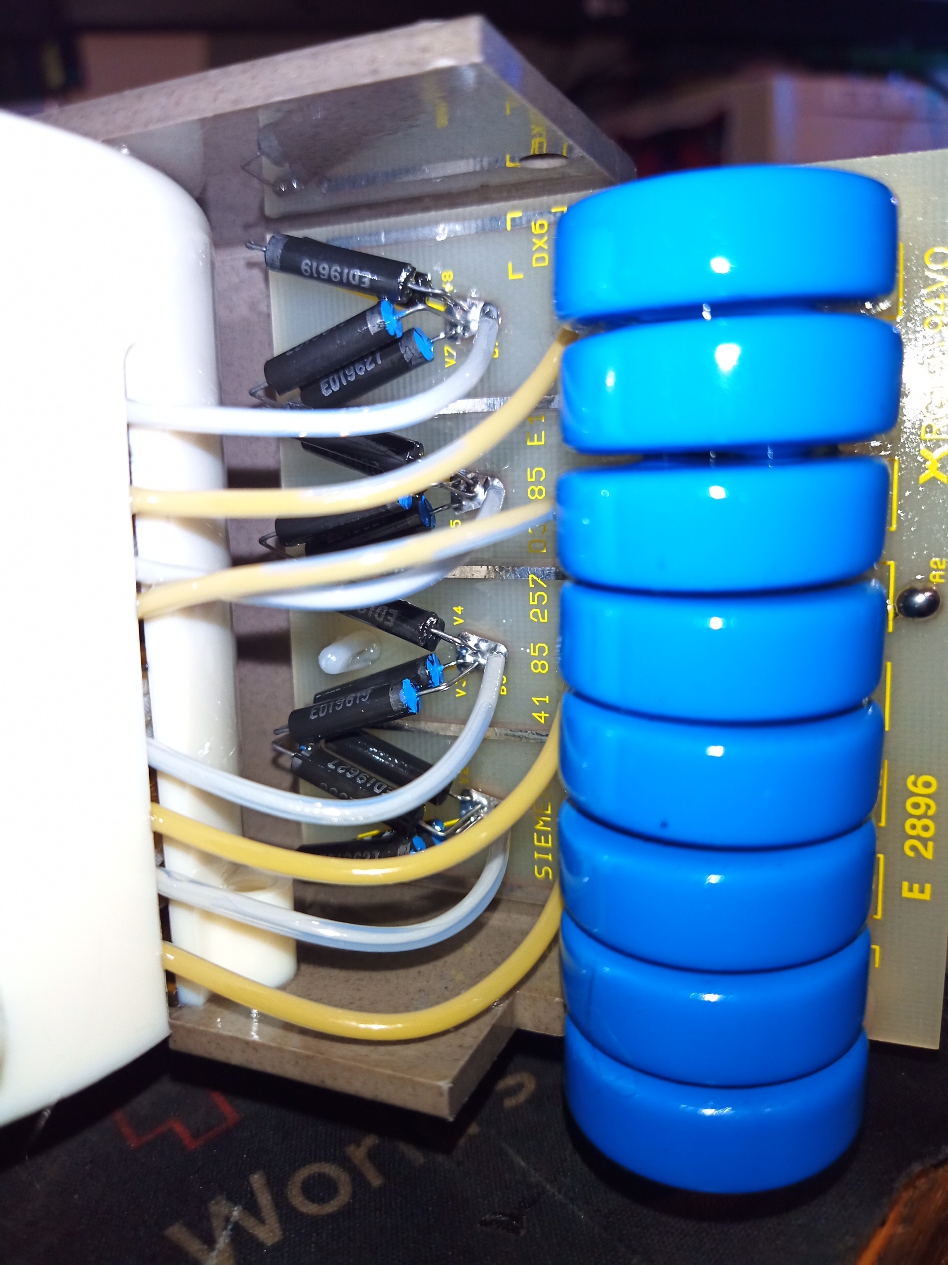
Voltage Multiplier
Behind the transformer lies the rest of the PSU – a 4-stage voltage multiplier. There are 4 separate secondary windings on the transformer, each feeding a voltage doubler. This is to keep the high-voltage stress on the transformer windings to a minimum, as the windings themselves only see 10kV per section, instead of the full output voltage of 80kV. This is increased to 20kV per section by the full-wave doubler, and as these are all in series the output end has the full 80kV.
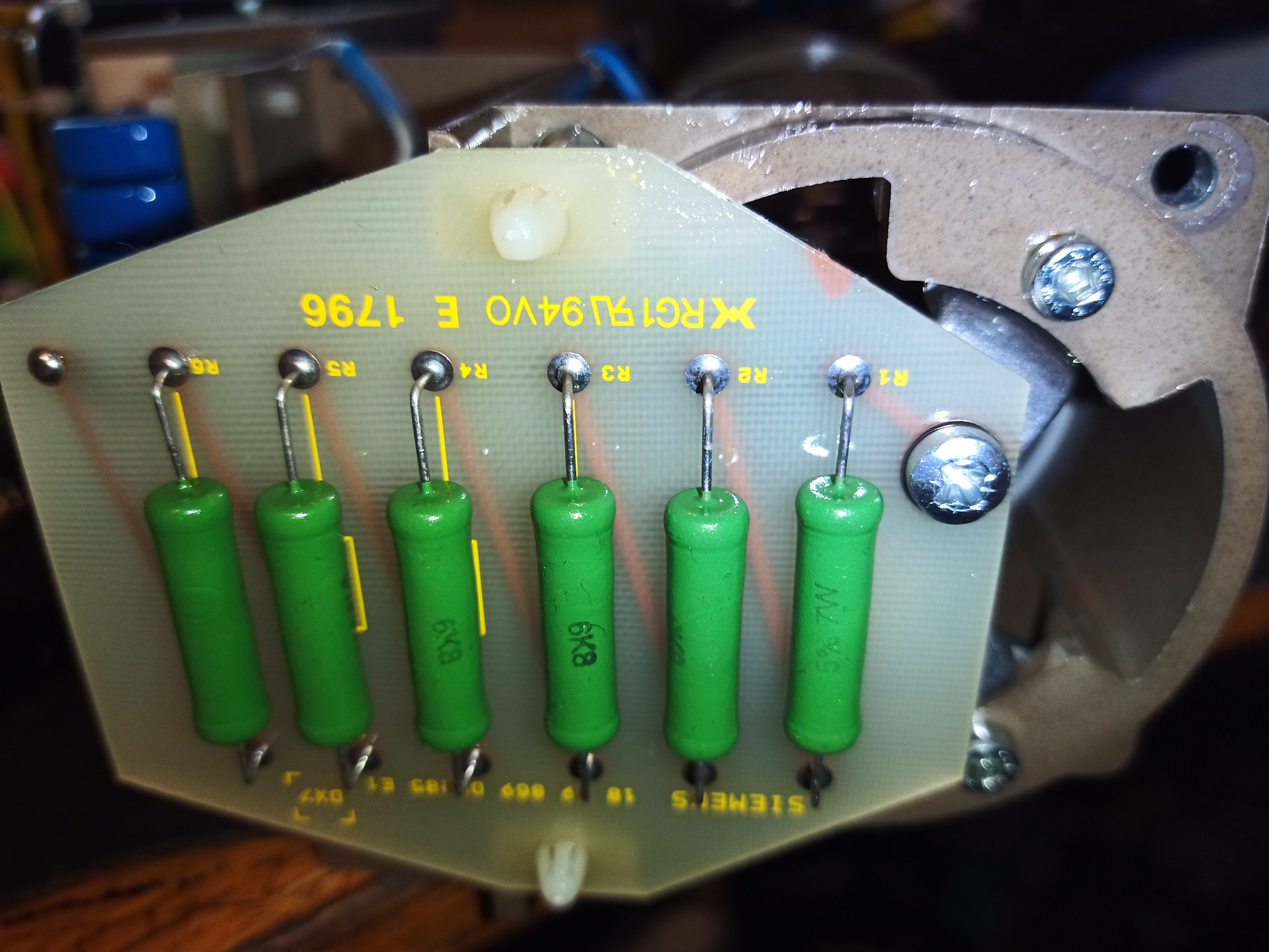
Ballast Resistor PCB
Over at the anode end of the X-Ray tube, is this board with 6x 6.8kΩ resistors in a series string for 40.8kΩ total. As this is in series with the tube anode, I presume it’s there for current limiting. At full power of 80kV 10mA, this stack will be dropping almost 500v & 4W of power.
X-Ray Aperture
At the bottom of the unit is the aperture where the X-Rays emerge. The connection to the centre of the voltage multiplier is also visible here.
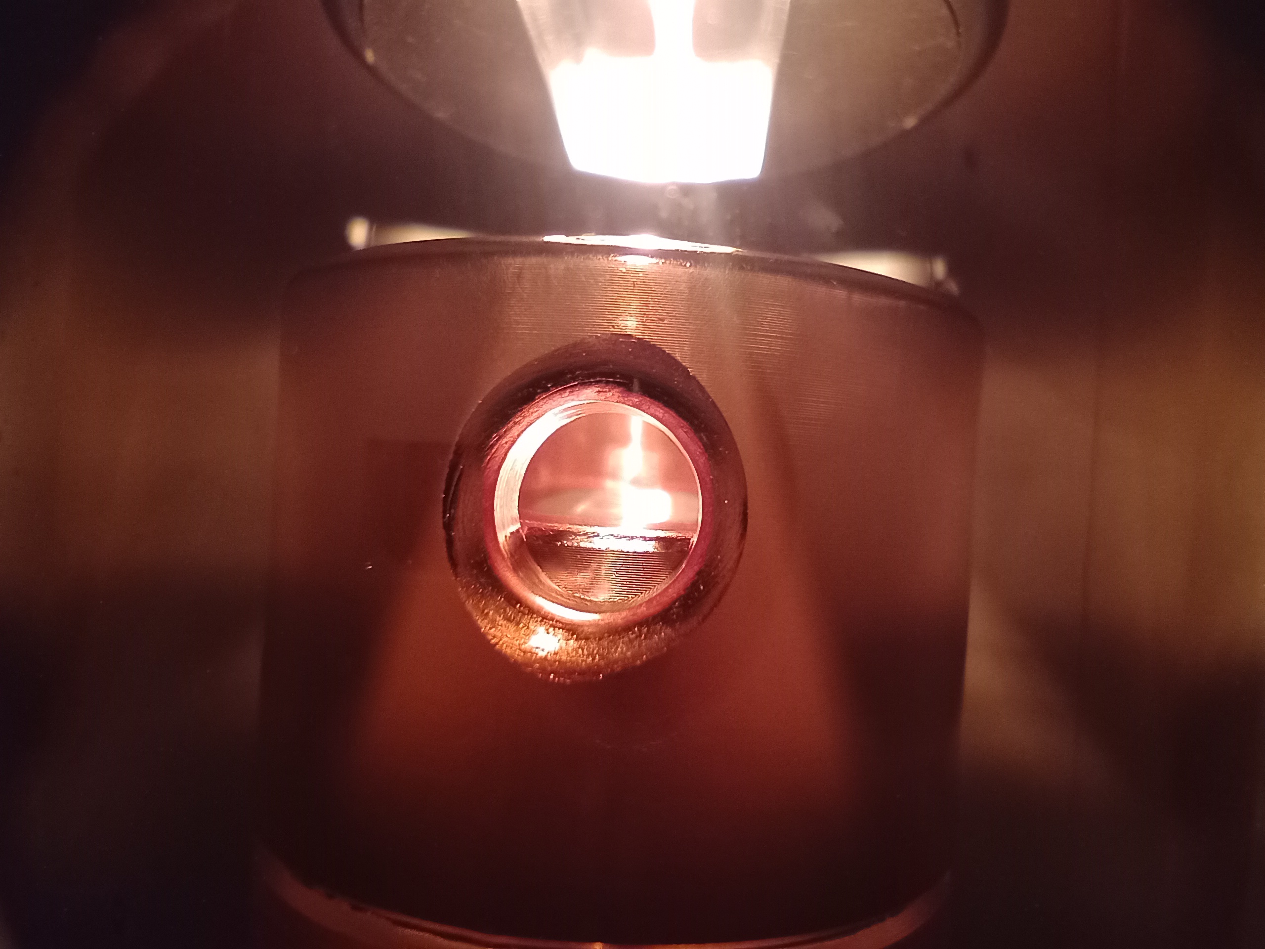
Filament Powered
Here is the view through the side of the tube with the filament powered at 4v. Filament current is about 2.6A. The copper heatsink block surrounding the Tungsten target is visible in the centre of the picture. The target is probably alloyed with Rhenium to give better longevity.
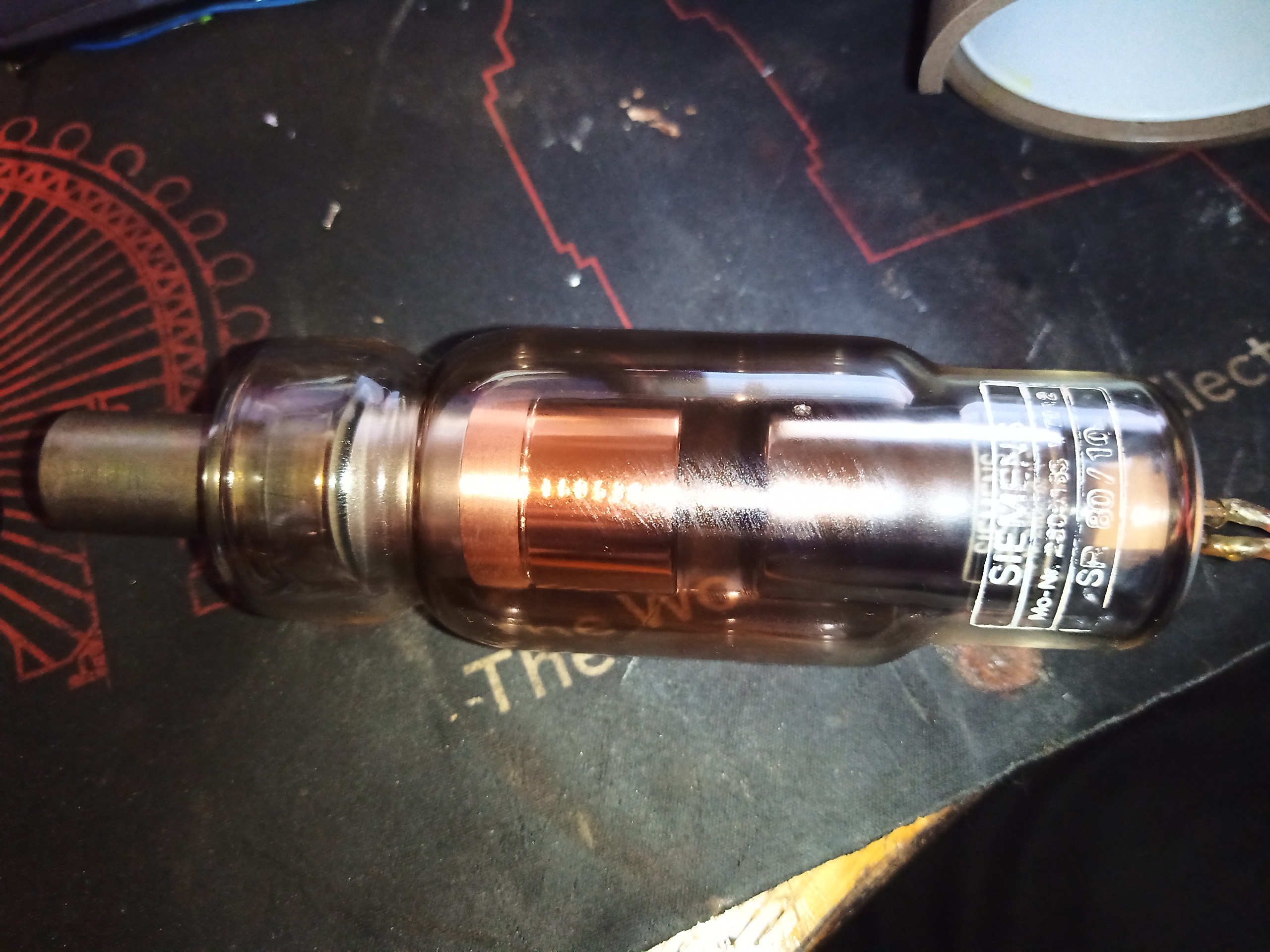
X-Ray Tube
The tube is held into the frame by a single bolt in the middle of the anode spider. Removing this bolt allows the tube to come out, and it’s heavy. This is not that surprising, since the anode of the tube is a solid chunk of Tungsten & copper!
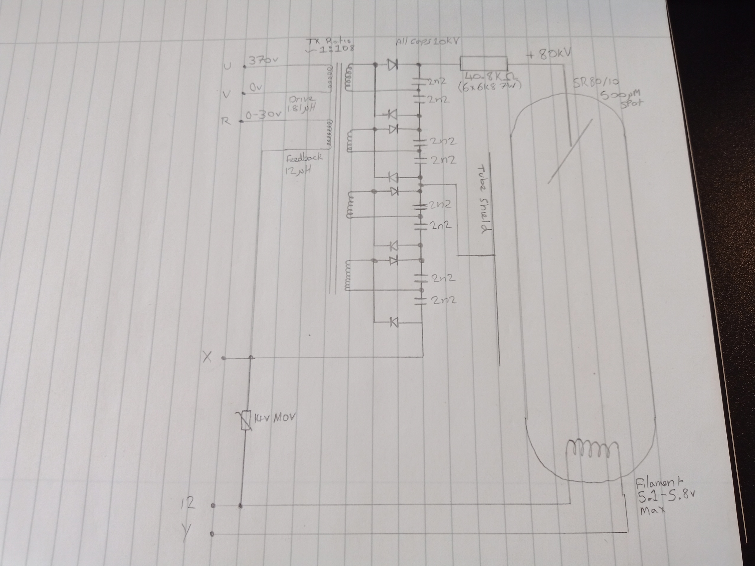
Orthophos 3 Head Schematic
Finally, here is the internal schematic of the head itself, with the pinout marked. The operating frequency of the transformer is 35kHz, and it is my understanding that these are operated in resonant mode. There’s no filament transformer, the drive for this is supplied externally. Output voltage feedback is via an auxiliary winding on the transformer.
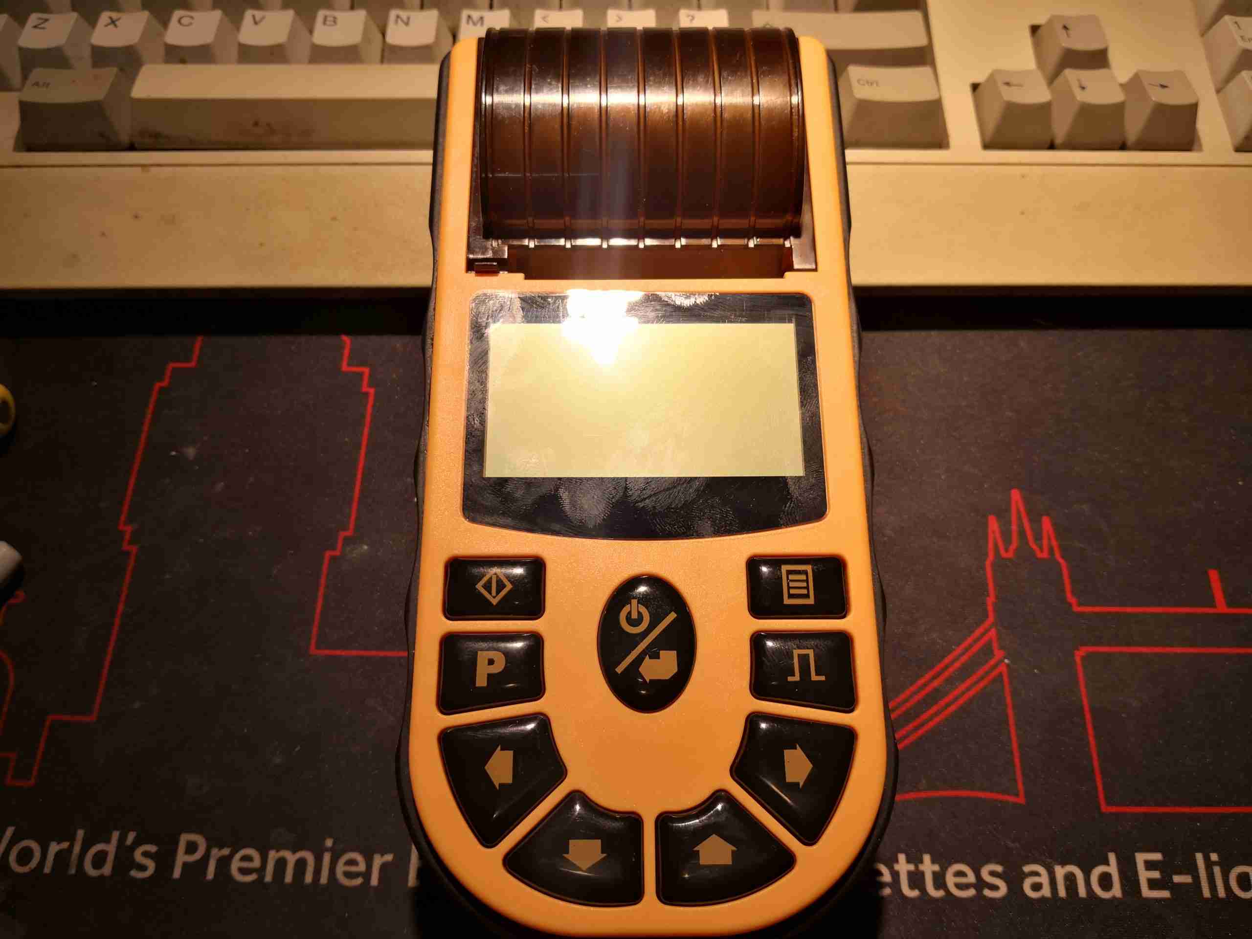
I figured it was about time I added to the medical kit, and since Contec, who makes my SPO² meter seems to have a decent level of manufacturing quality, one of their ECG machines seemed like a good choice. This is the ECG80A handheld Electrocardiograph. This is a single channel, 12 lead unit – meaning it’s a full 12 lead ECG, but it records one lead at a time, in sequence.
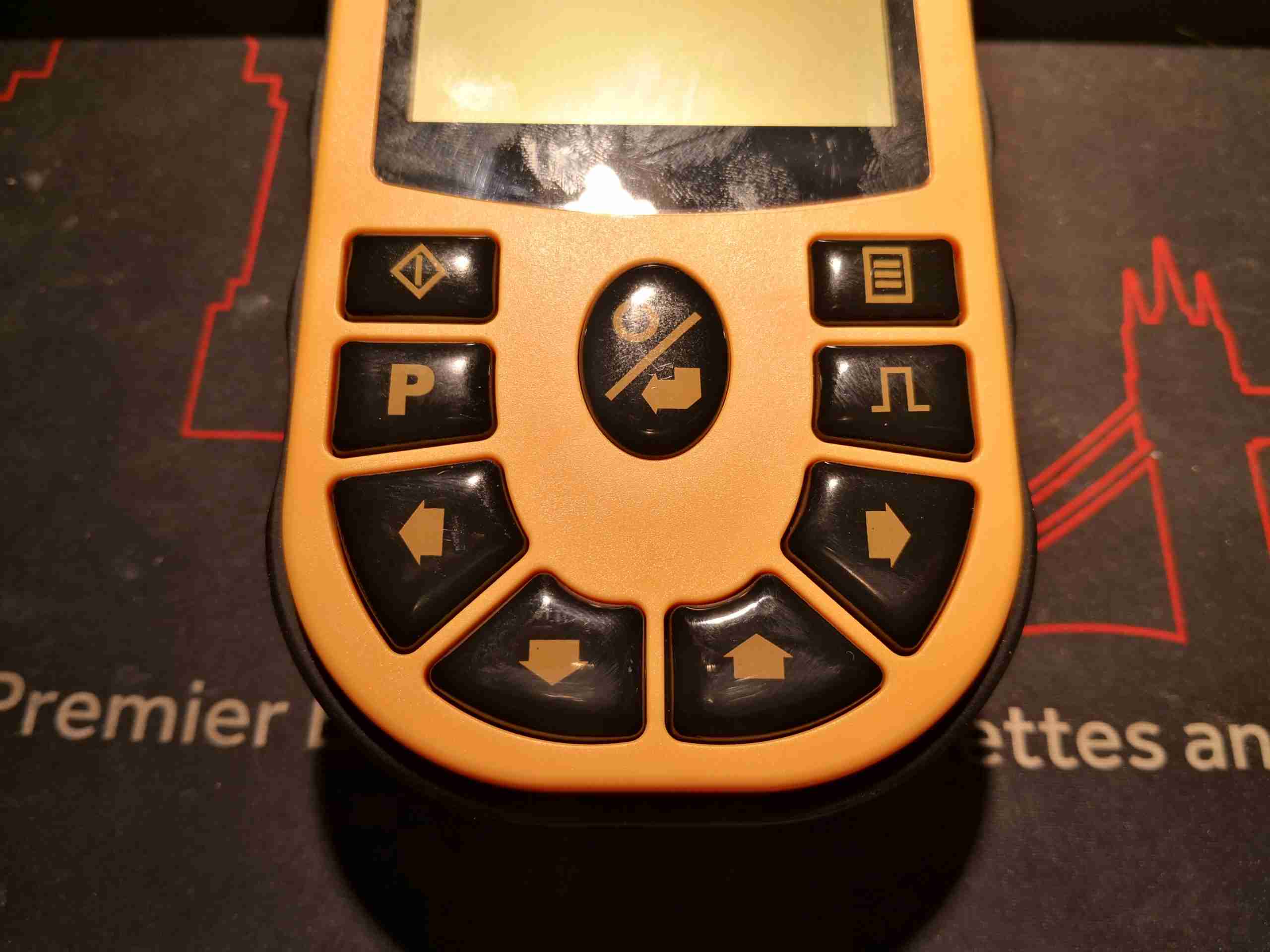
Control Buttons
Control is via the front panel, with some large buttons.
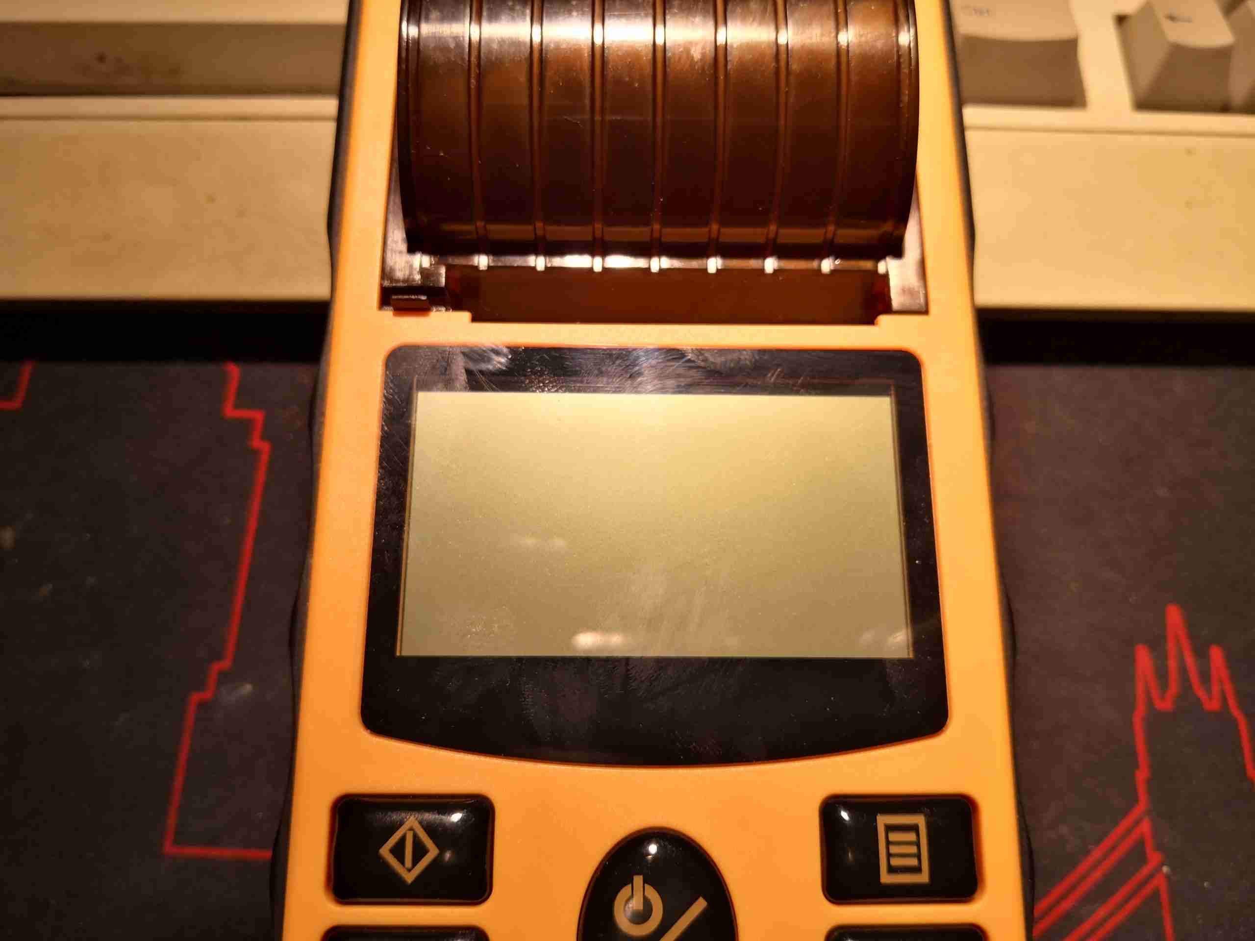
LCD Display
Readout is provided on a dot-matrix LCD, which is brightly backlit. There’s a thermal printer for rhythm strips, printing onto 50mm wide paper rolls.
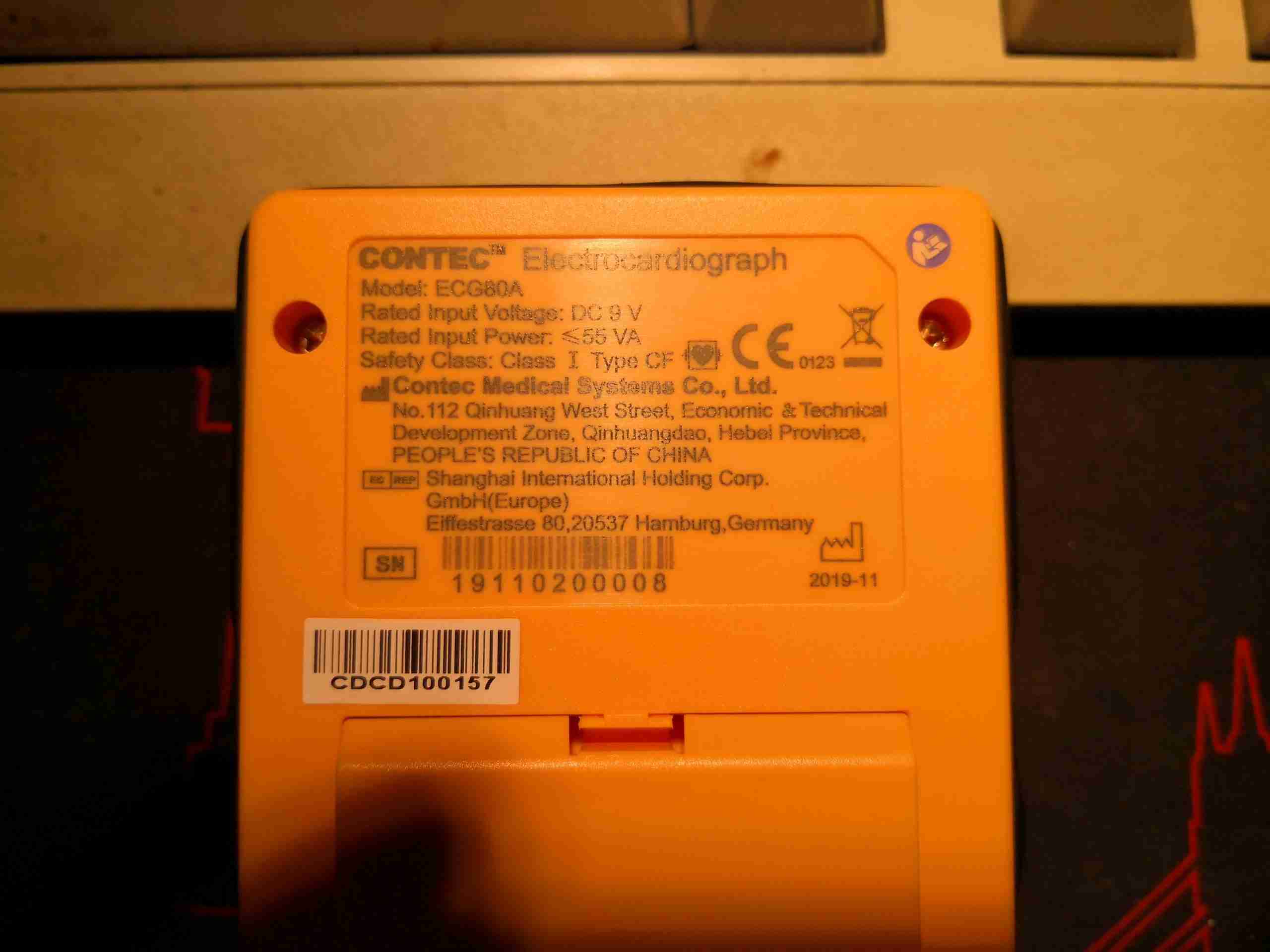
Labelling
The rear has the laser-marked rating plate, with all the specifications & regulatory markings. From the serial numbering, it looks like my unit was manufactured on 3/11/19, and was the 8th unit off the production line. Underneath can be seen the top of the battery pack, which just clips into place. There aren’t any markings on this at all, but I do know from the manual it’s a 7.4v 2S Li-Ion pack, energy capacity is another unknown, but there is very little weight to the battery, so it can’t be that large.
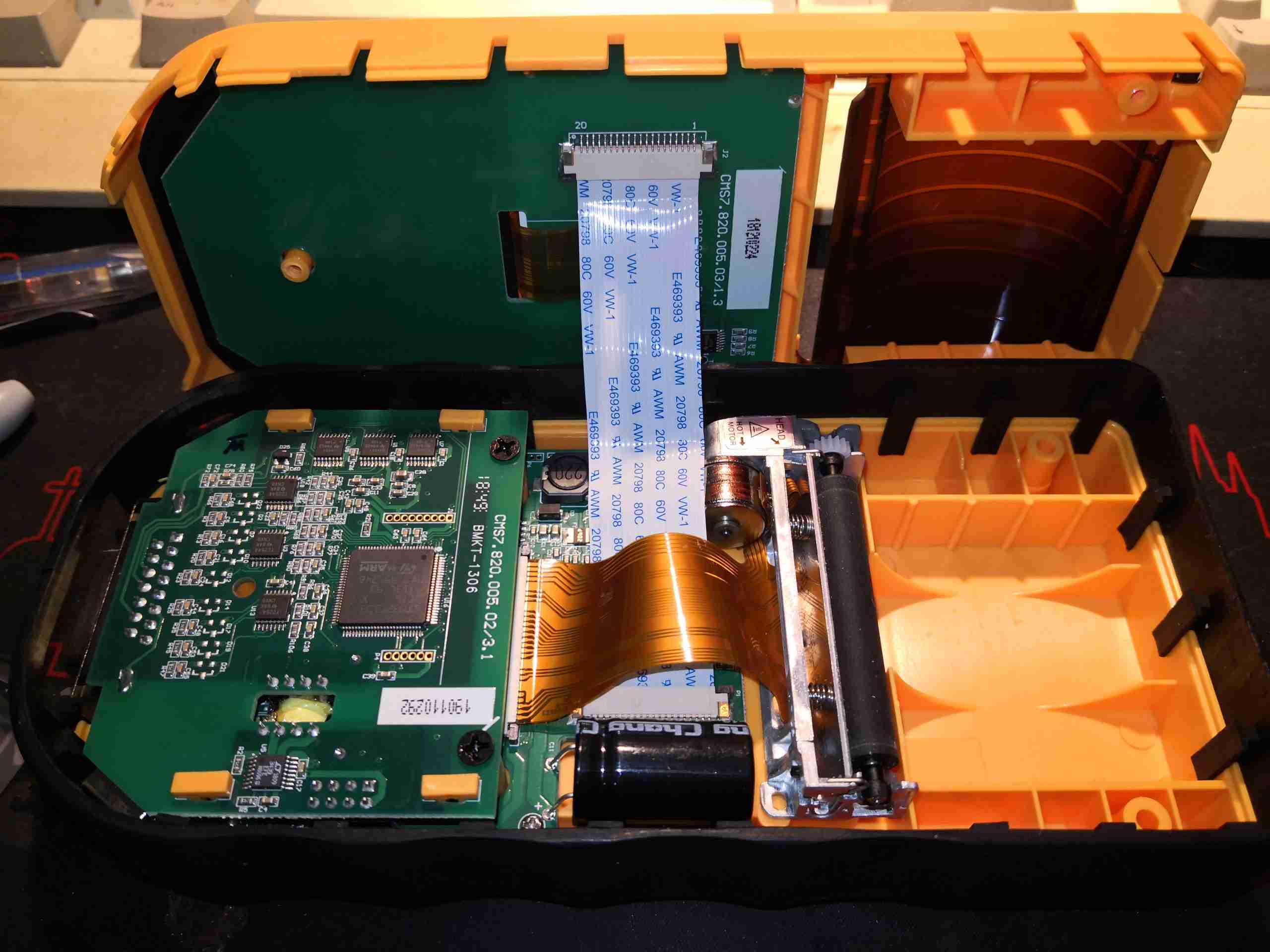
Internals
3 Philips screws hold the unit together, and once those are removed, the shell halves separate. The FFC to the LCD & button pad is currently keeping things connected together.
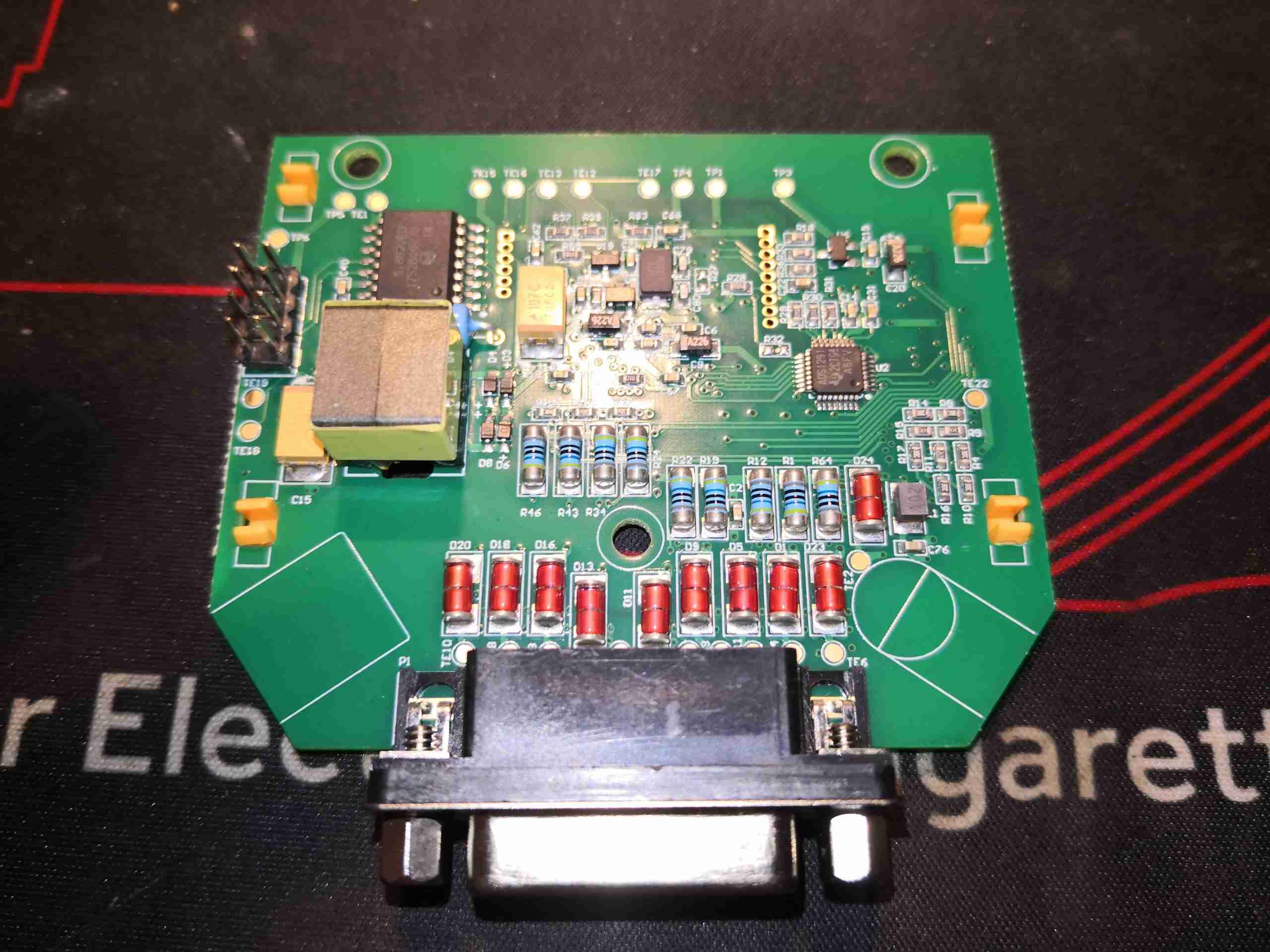
Acquisition PCB
The first of 3 PCBs inside the shell is the acquisition PCB, with all the patient-connected circuitry. The DB-15 connector is on the right hand side, where the ECG leadset connects.
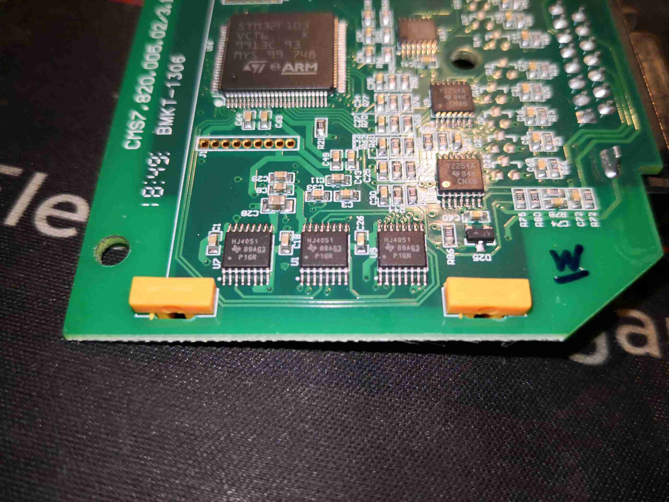
Signal Switching
The bottom edge of the PCB has a trio of HJ4051 high speed analog multiplexers, which are switching the ECG leads onto the Ultra-Low Power Op-Amps on the right, a trio of TCL2254A devices from Texas Instruments, before being sent on to the ADC.
Acquisition PCB Bottom
The bottom of the PCB has the DB-25 connector, along with the input protection diodes & resistors. This array of protection components serves two purposes – protection of the instrument against defibrillator voltages & protection of the patient from electrical shock by the instrument.
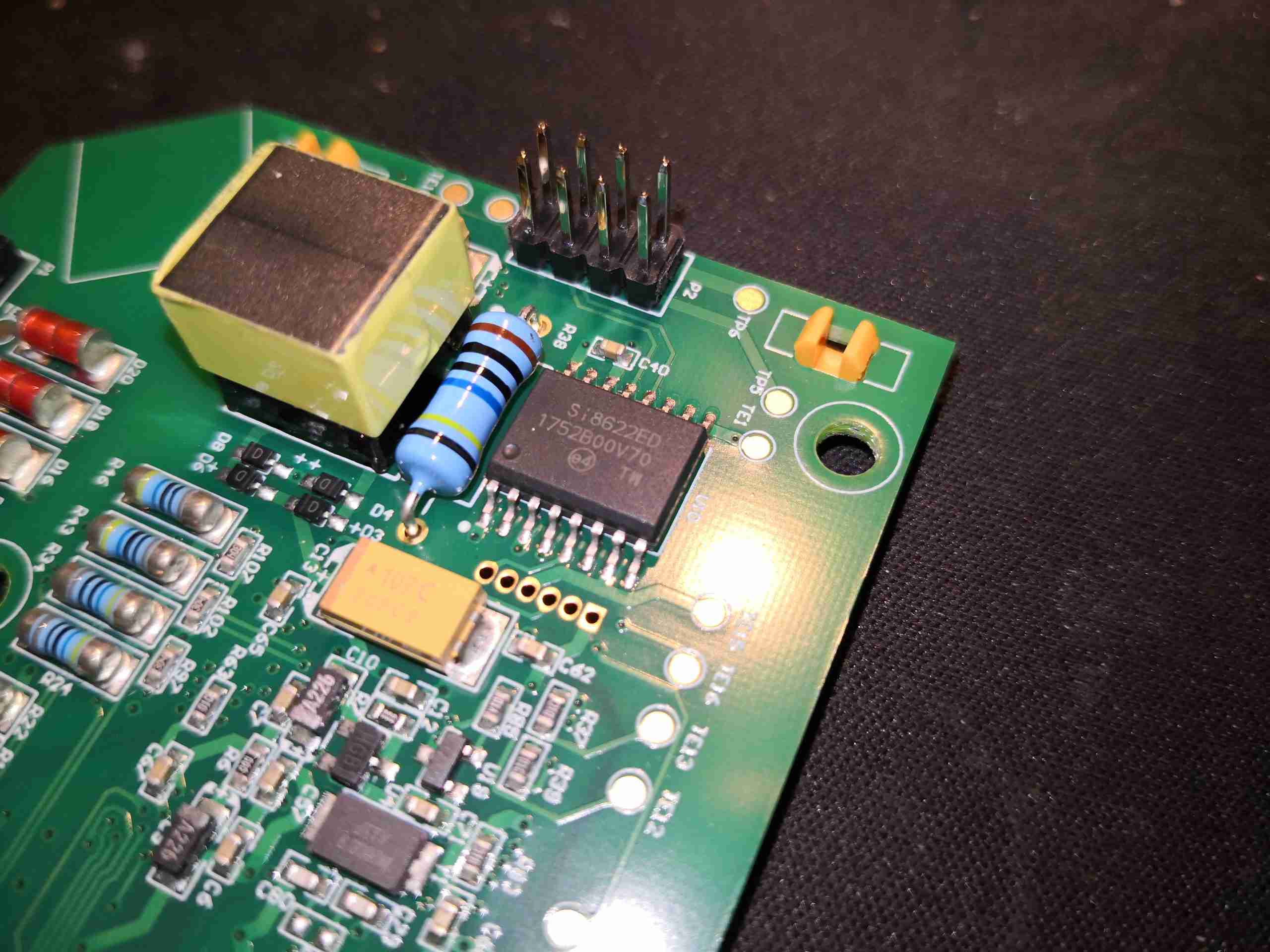
Signal Isolation
A 5kV isolation barrier is provided between the rest of the unit & the acquisition board, both for the data path & power path. The isolation transformer is visible on the left here, next to the 8-pin header that connects to the main PCB. There’s a 100MΩ resistor across the isolation barrier, probably for ESD bonding. To the right of that is a SiLabs Si8622ED single channel digital isolator IC.
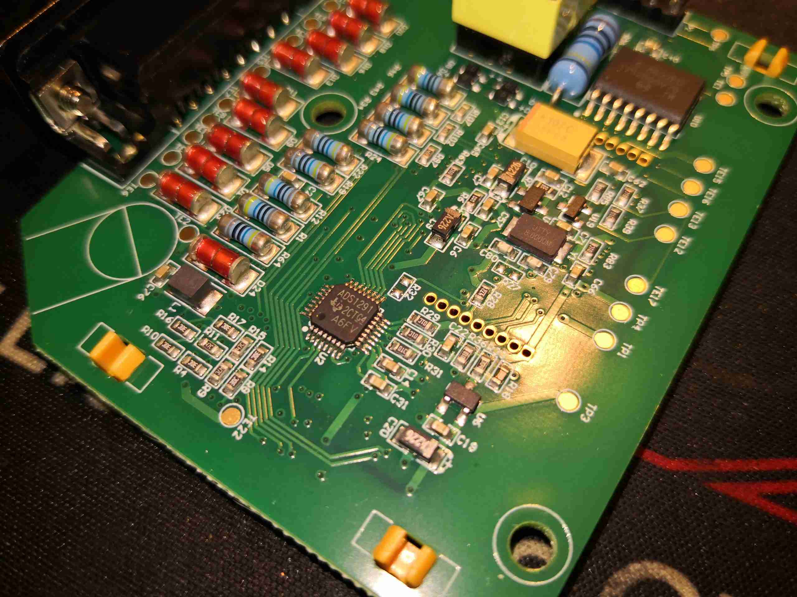
ADC
The final bit of conversion of the input waveform is performed by a Texas Instruments ADS1291, a 2-channel 24-bit Analogue front-end specifically designed for Bioelectrical measurement such as ECG. This contains a ΔΣ ADC, and a pair of Programmable Gain Amplifiers on the input, together with some multiplexing. This communicates via SPI to the host microcontroller.
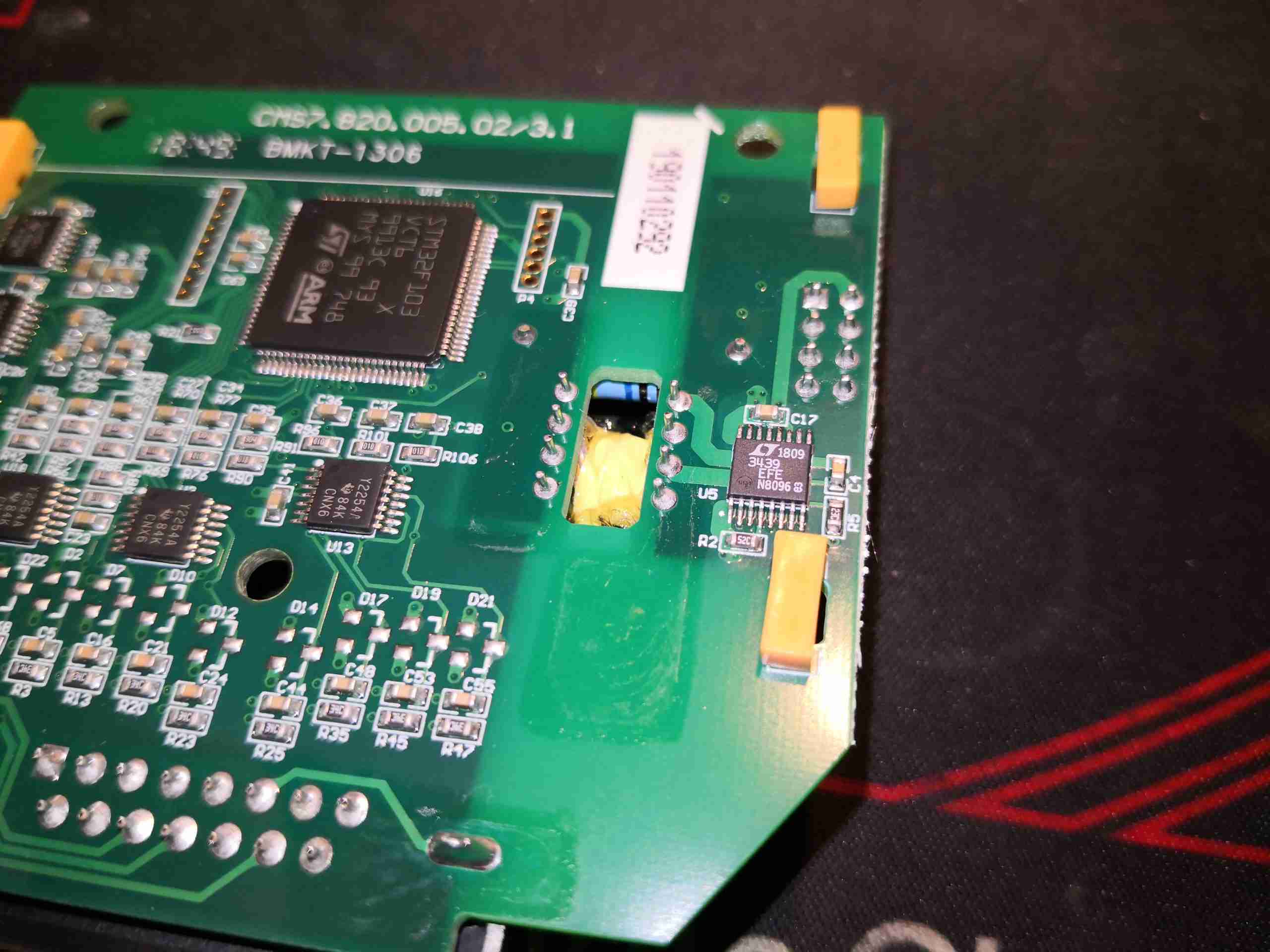
Isolated Power Supply
Power is transferred across the isolation gap through the transformer, driven by a Linear Tech LT3439 slew-rate controlled ultra low noise isolated switching supply driver.
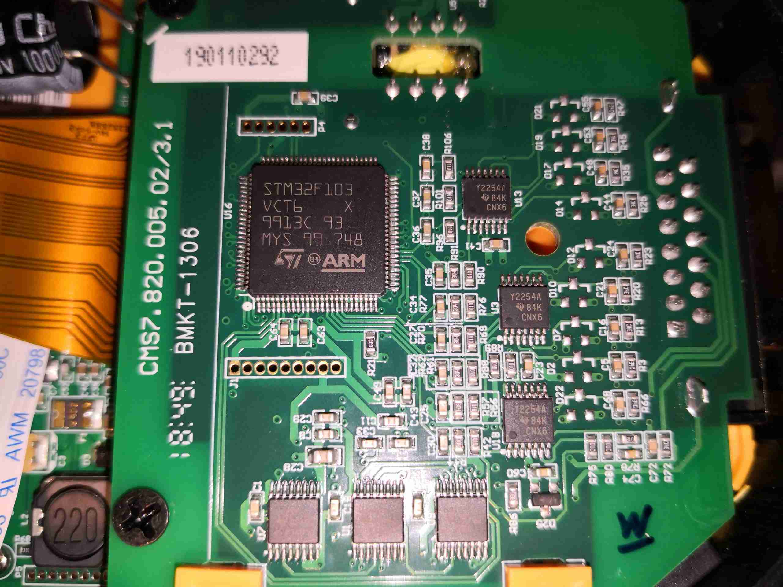
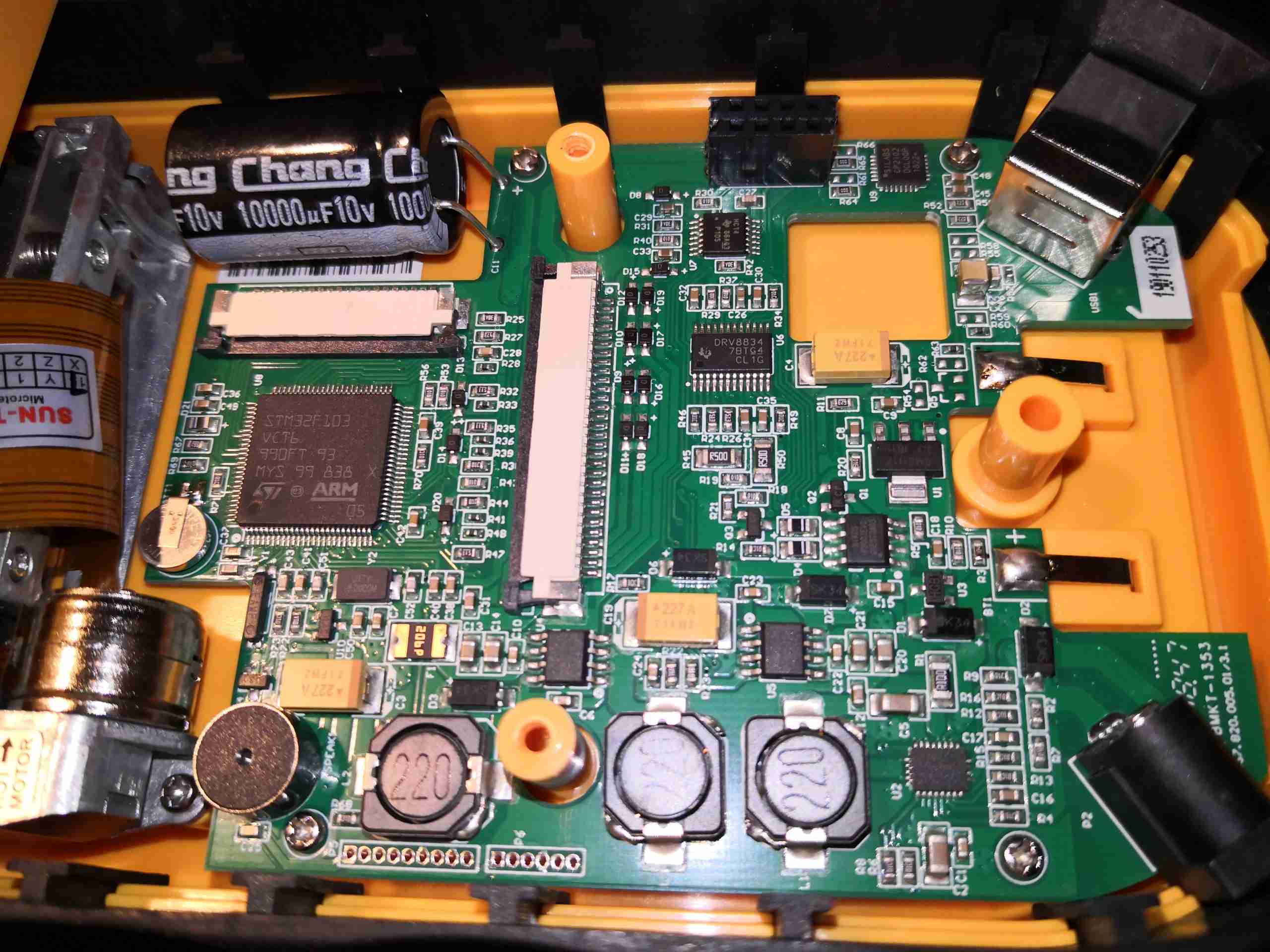
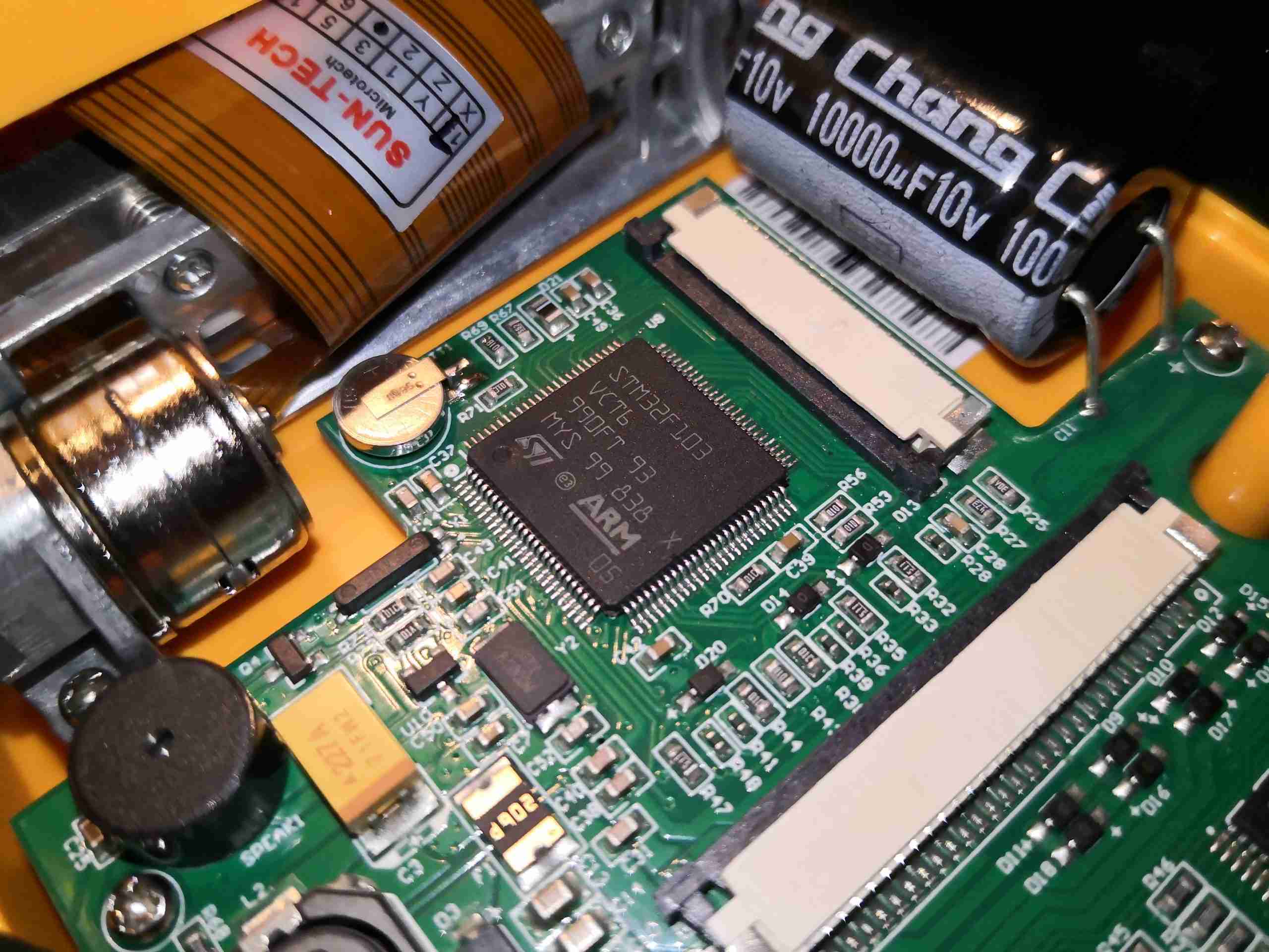
Mainboard
Underneath the acquisition board is the main PCB itself, with the rest of the support electronics. On the lower edge of the board are the power supplies, the main microcontroller on the left, another STM32F103, USB Serial communications top right, and DC input bottom right.
Main CPU
Here’s the main microcontroller with it’s support components. This will be receiving a datastream from the acquisition microcontroller, probably I²C considering the single-channel digital isolation, and further decoding this for either display on the LCD, printing on the thermal paper or sending as a datastream over USB Serial to a PC.
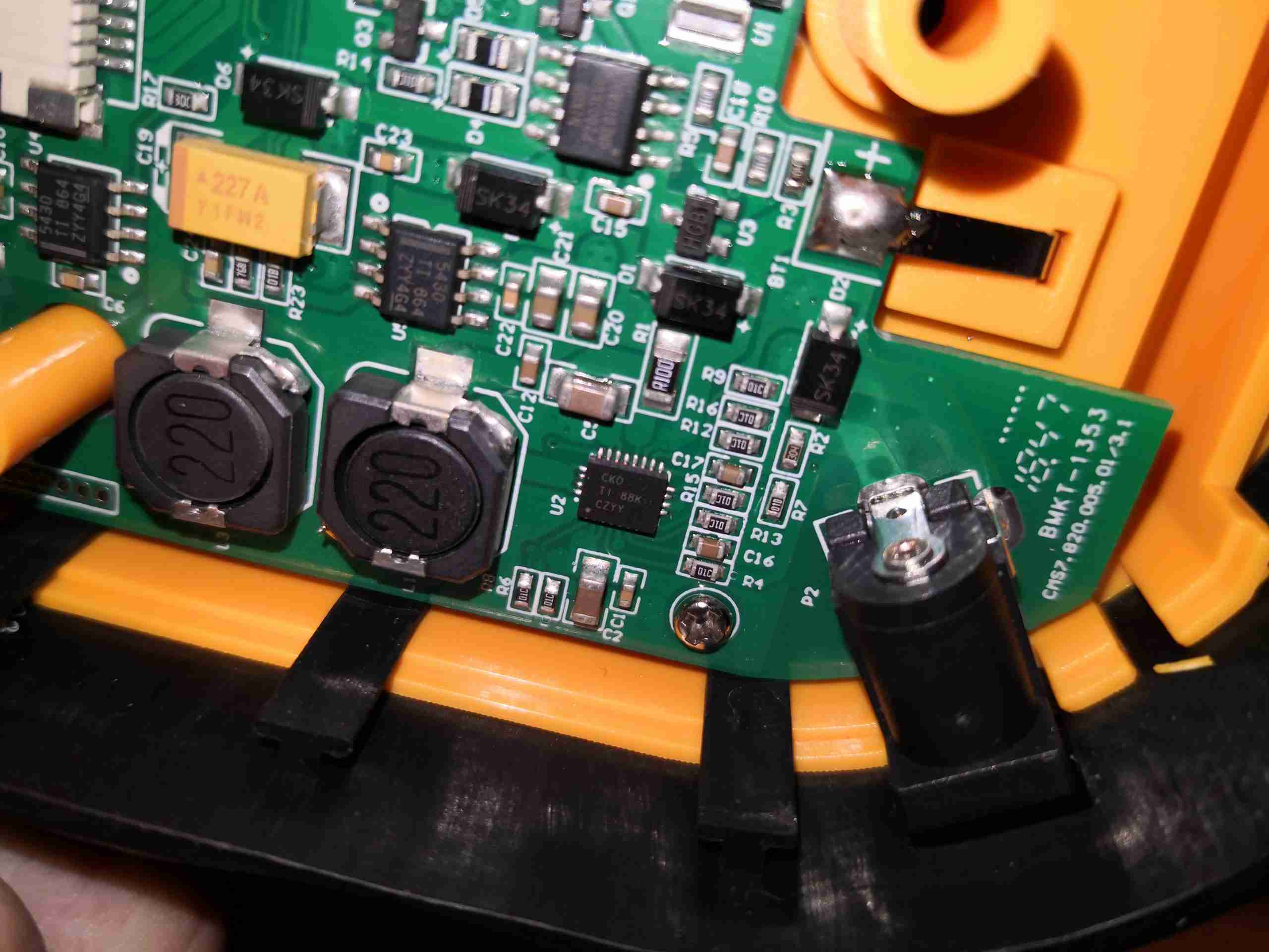
Power Supplies
The onboard 2S 7.4v Lithium Ion battery is handled by a Texas Instruments bq24103A Synchronous switched-mode charge management IC here, just to the left of the barrel jack. It’s inductor is just to the left of the IC. This is a fairly nice chip, with support for up to 3 series cells with full auto sensing.
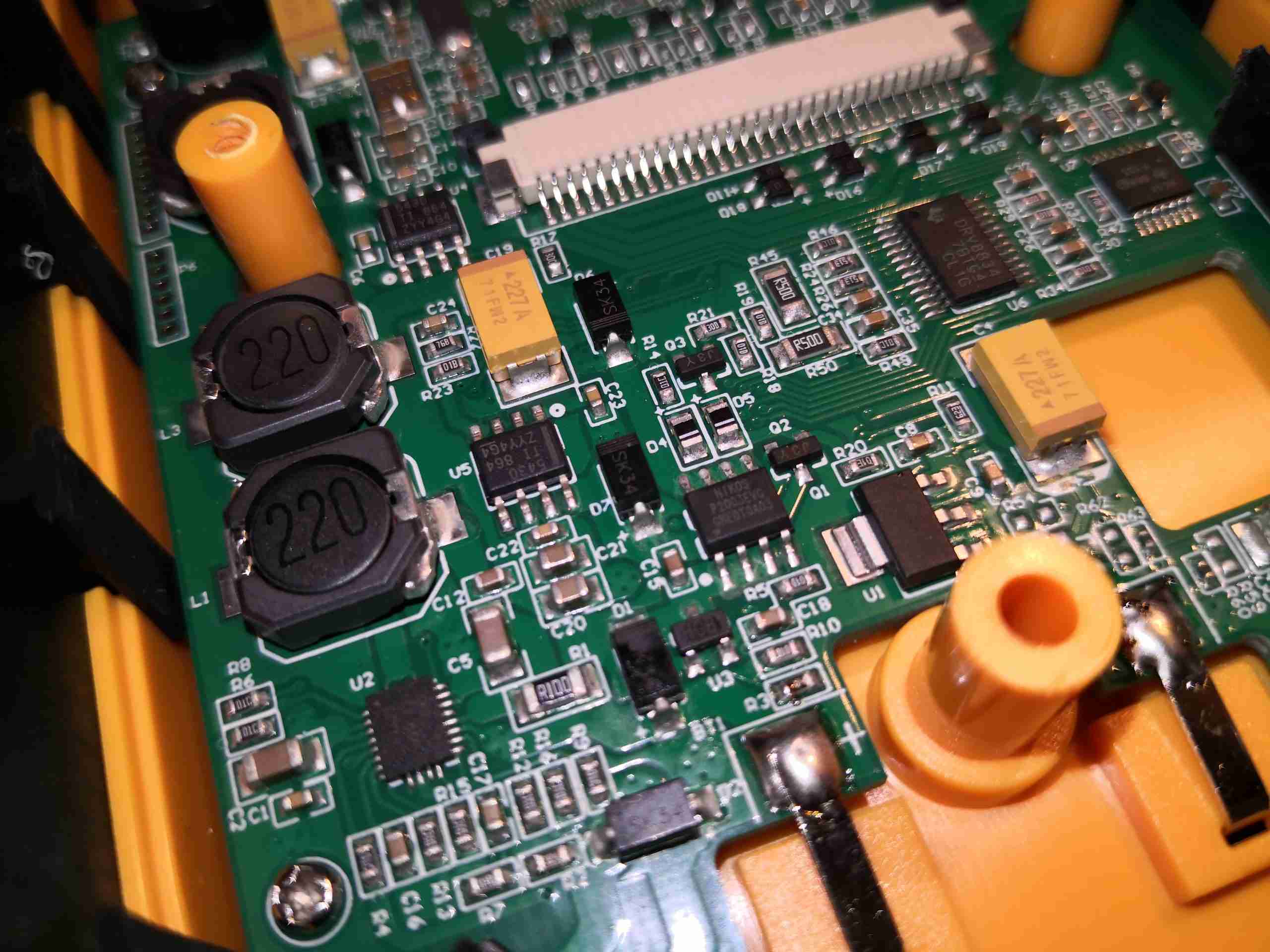
DC-DC Converters
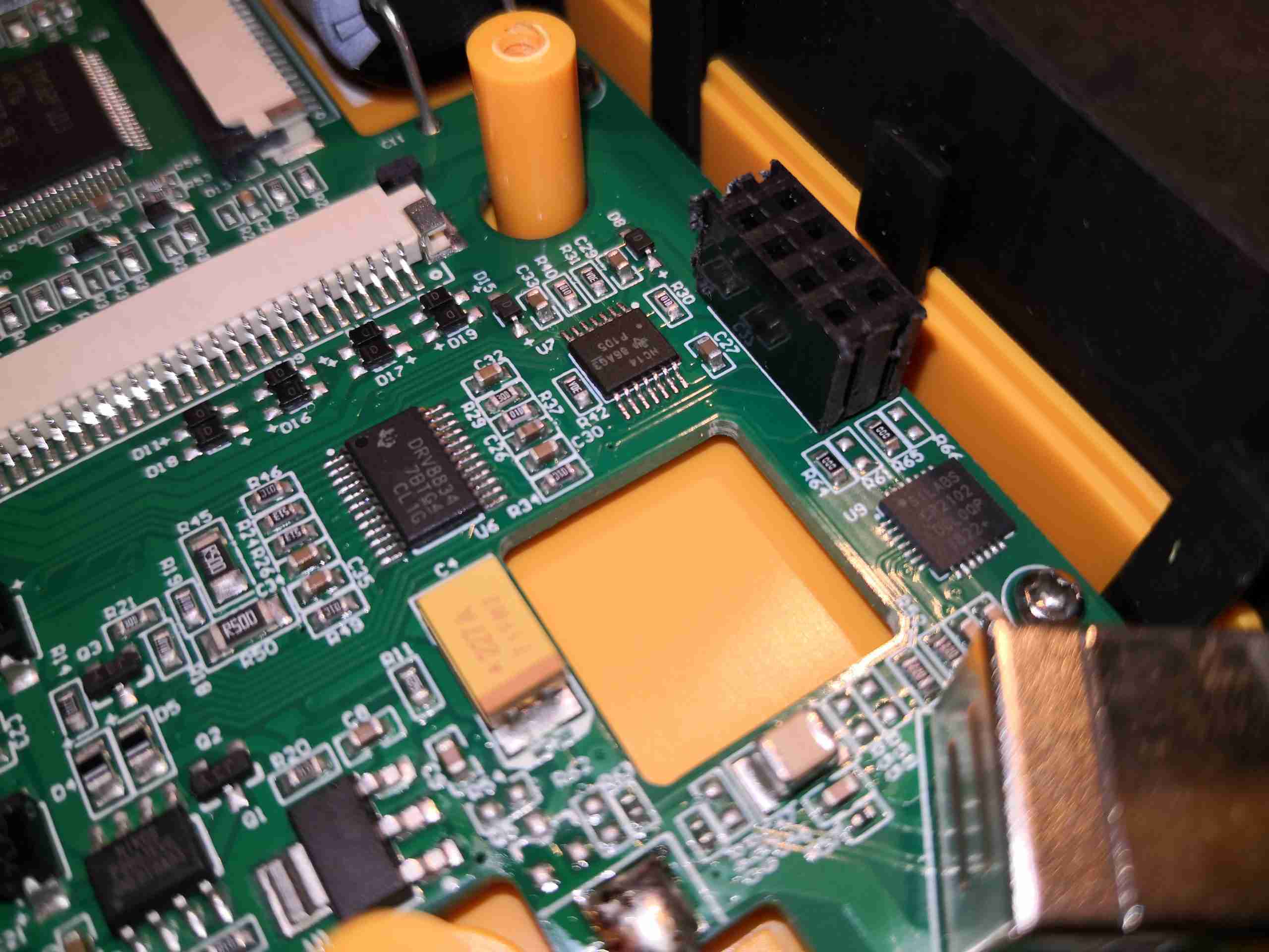
Other power supply rails are dealt with via a pair of TPS5430 buck converters, again from TI. Their associated inductors are along the left side of the board. There’s also an LM1117-3.3 linear regulator for a low-noise supply, possibly for the microcontroller power rail. There’s also a few discrete switching components, and a DRV8834 bipolar stepper driver for the printer.
USB Interface
Finally, in the corner of the board is the USB connector, with a SiLabs CP2102 USB UART IC. This interface is used with the optional PC Software. The routed hole in the PCB is clearancing for the isolation transformer of the acquisition board.
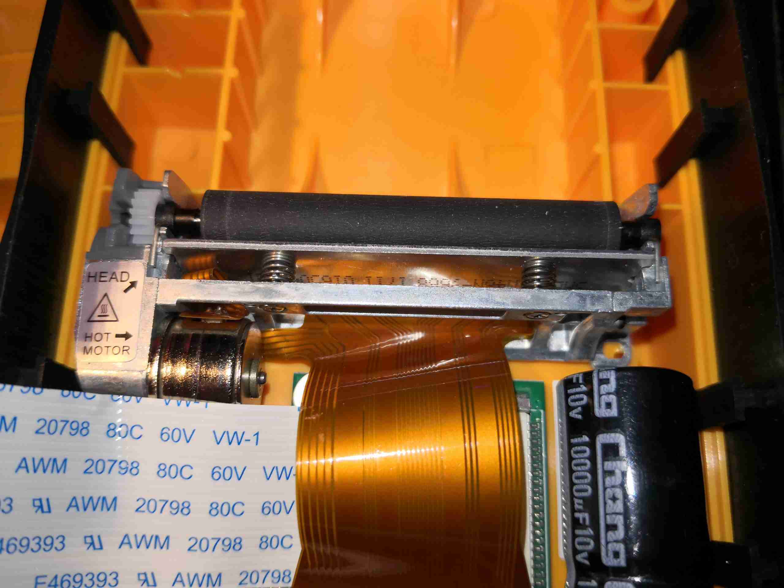
Printer Module
Here’s the printer module, at the top of the shell. There’s a tiny stepper motor on the lower left that moves the paper past the print head, which is the bar mounted on springs across the centre. The odd thing with this is to load the paper, the black rubber pinch roller has to be completely removed from the printer, the paper placed across the print head, and the roller clipped back into place – instead of the roller being mounted on the front cover like on most thermal printers.
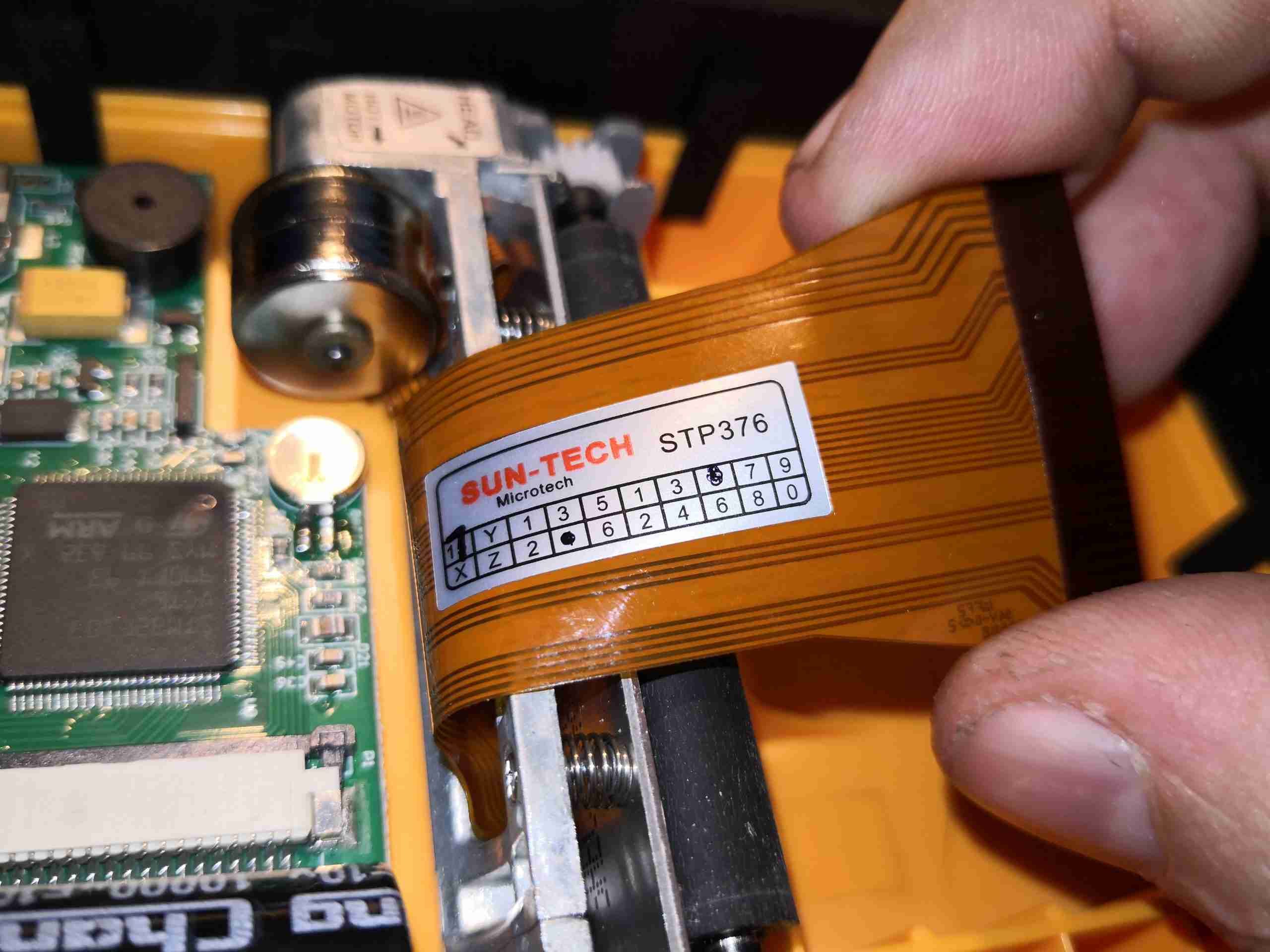
Printer Label
The printer module is manufactured by Sun-Tech, the STP376. I’ve not managed to find any information on this at all, either the manufacturer, or the part number. I did find a SunTech, in the medical sector, but their logo is very different from the labelling here.
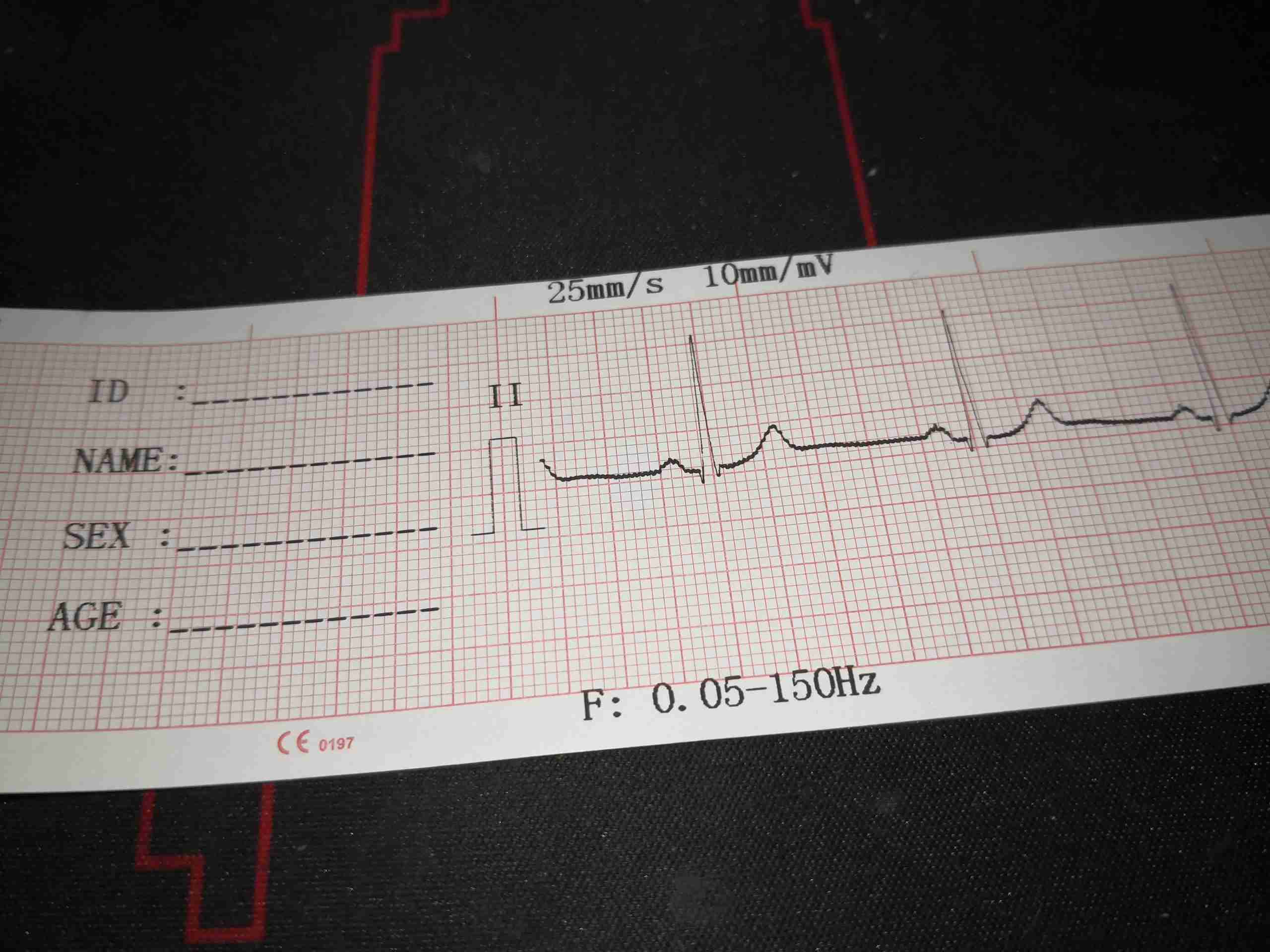
Lead II Example Printout
Here’s an example of the print quality of the unit, which just so happens to be lead II taken from me! It’s pretty good overall, with nice clear printing. There is a little interference on the trace that can be seen, but that’s not the ECG’s fault – this trace was obtained in a relatively EMC-noisy environment. The unit first prints a section for patient details, then the lead ident & 1mV calibration mark, then the actual trace. Machine settings are printed in the top & bottom margins, showing the print speed, sensitivity setting, and any applied frequency settings. There is a little bit of interference on the A full 12-lead printout is roughly 3 seconds per lead in sequence, and takes up about 1.2m of paper at standard 25mm/s speed setting.
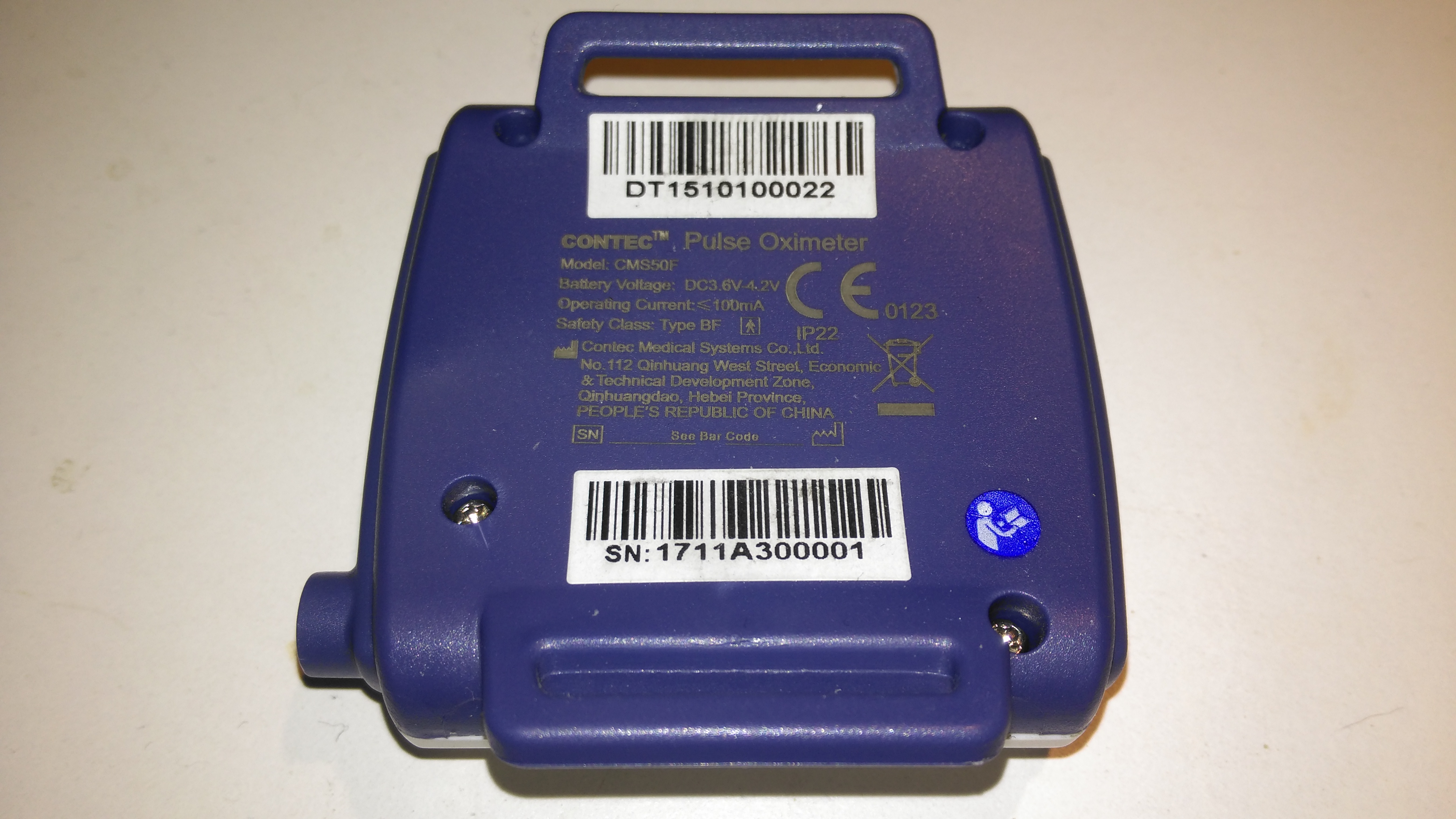
The rear has the specifications, laser-marked into the plastic. The serial numbers are just sticky labels though, and will come off easily with use.
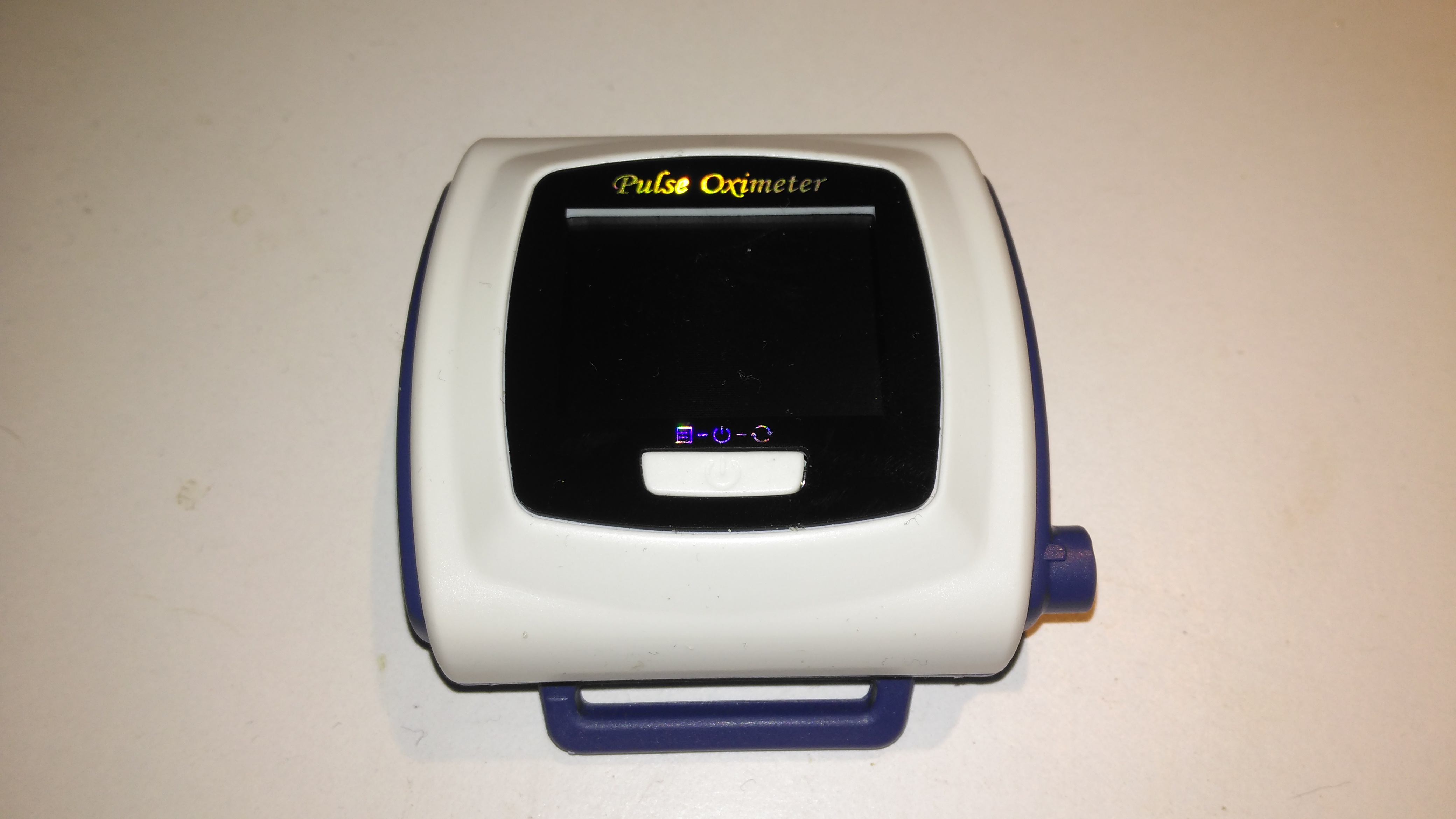
Contec CMS-50F
This is the Contec CMS-50F wrist-mounted pulse oximeter unit, which has the capability to record data continuously to onboard memory, to be read out at a later time via a USB-Serial link. There is software supplied with the unit for this purpose, although it suffers from the usual Chinese quality problems. The hardware of this unit is rather well made, the firmware has some niggles but is otherwise fully functional, however the PC software looks completely rushed, is of low quality & just has enough functionality to kind-of pass as usable.
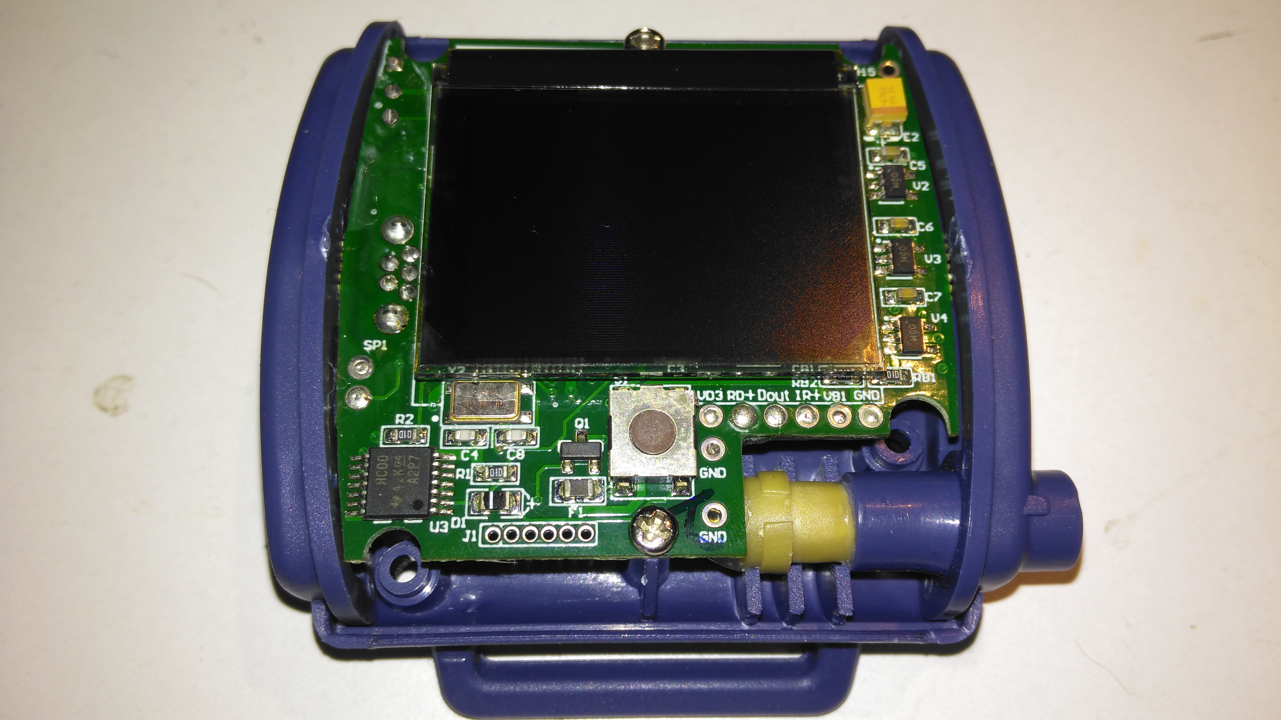
Top Cover Removed
A total of 4 screws hold the casing together, once these are removed the top comes off. The large colour OLED display covers nearly all of the board here. The single button below is the user interface. The connection to the probe is made via the Lemo-style connector on the lower right.
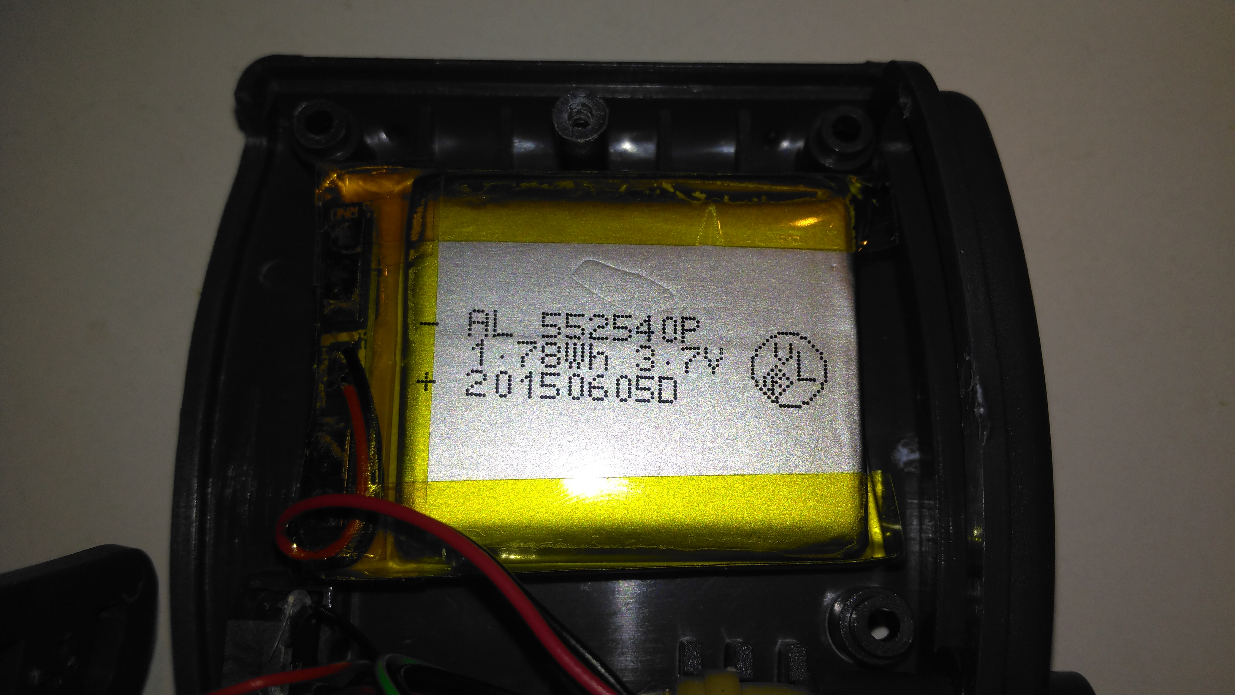
Lithium Cell
Power is provided by a relatively large lithium-ion cell, rated at 1.78Wh.
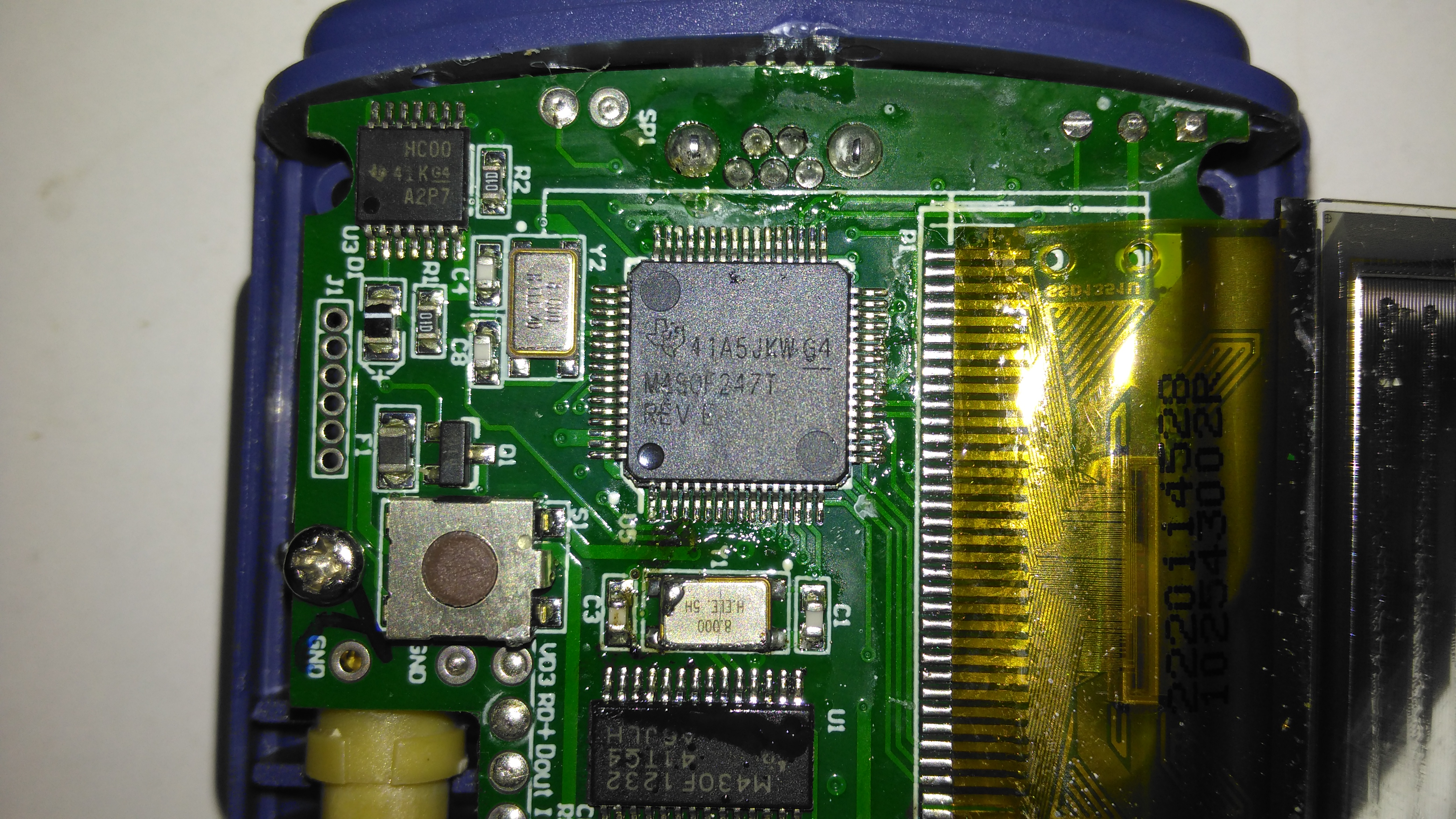
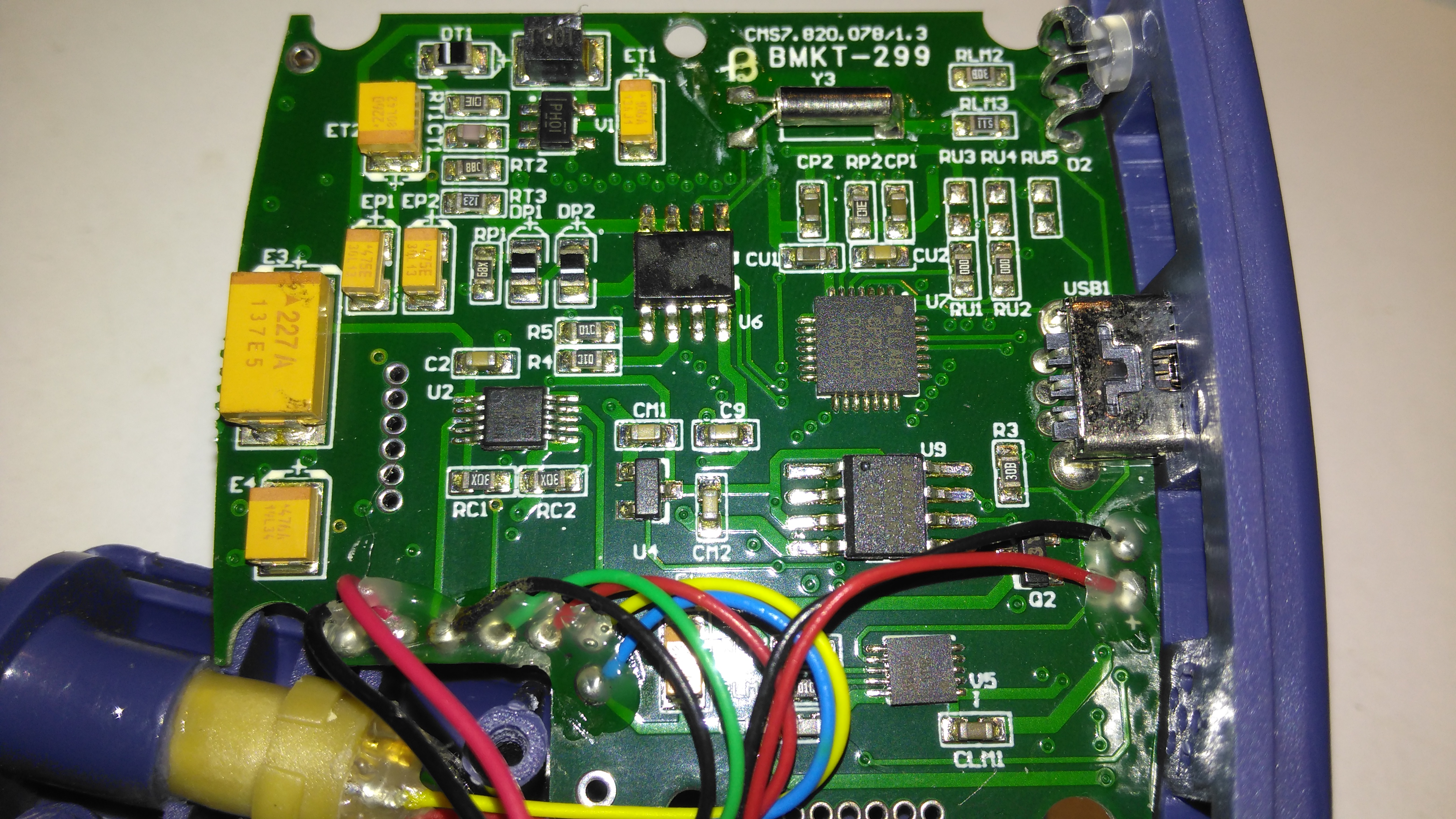
Main Processor
All the heavy lifting work of the LCD, serial comms, etc are handled by this large Texas Instruments microcontroller, a MSP430F247. The clock crystal is just to the left, with the programming pins. I’m not sure of the purpose of the small IC in the top left corner, I couldn’t find any reference to the markings.
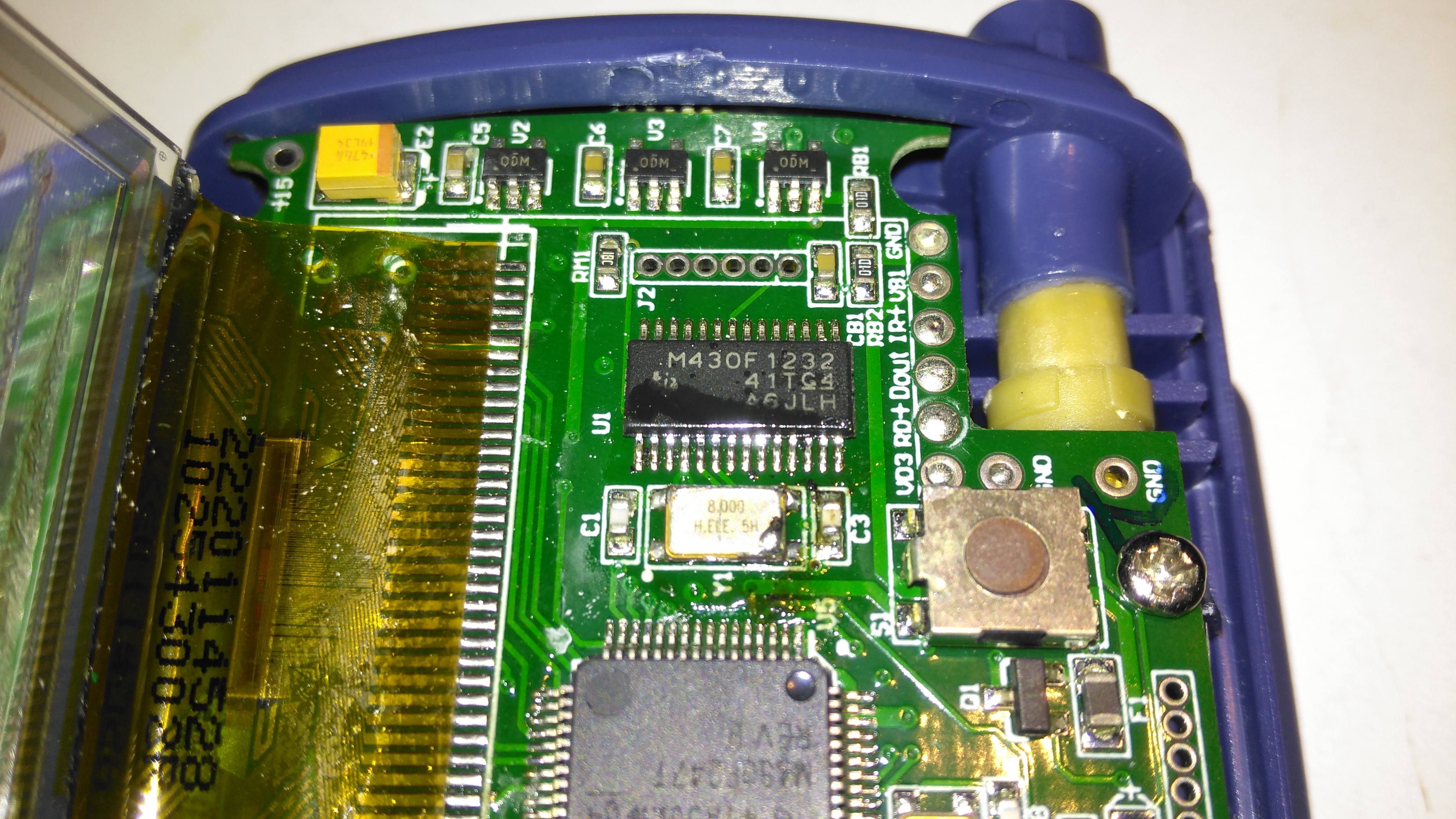
Aux Processor
The actual pulse oximetry sensor readings seem to be dealth with by a secondary microcontroller, a Texas Instruments M430F1232 Mixed-Signal micro. This has it’s own clock crystal just underneath. The connections to the probe socket are to the right of this µC, while the programming bus is broken out to vias just above. The final devices on this side of the board are 3 linear regulators, supplying the rails to run all the logic in this device.
Main PCB Rear
The rear of the PCB has the SiLabs CL2102 USB-Serial interface IC, the large Winbond 25X40CLNIG 512KByte SPI flash for recording oximetry data, and some of the power support components. The RTC crystal is also located here at the top of the board. Up in the top left corner is a Texas Instruments TPS61041 Boost converter, with it’s associated components. This is probably supplying the main voltage for the OLED display module.
Here’s a piece of medical equipment that in recent years has become extremely cheap, – a Pulse Oximeter, used to determine the oxygen saturation in the blood. These can be had on eBay for less than £15.
Powered On
This one has a dual colour OLED display, a single button for powering on & adjusting a few settings. These cheap Oximeters do have a bit of a cheap plastic feel to them, but they do seem to work pretty well.
Pulse Oximeter
After a few seconds of being applied to a finger, the unit gives readings that apparently confirm that I’m alive at least. 😉 The device takes a few seconds to get a baseline reading & calibrate the sensor levels.
Main PCB Top
The plastic casing is held together with a few very small screws, but comes apart easily. here is the top of the main board with the OLED display panel. There appears to be a programming header & a serial port on the board as well. I’ll have to poke at these pads with a scope to see if any useful data is on the pins.
Main PCB Bottom
The bottom of the board has all the main components of the system. The microcontroller is a STM32F03C8T6, these are very common in Chinese gear these days. There’s a small piezo beeper & the main photodiode detector is in the centre.
There is an unpopulated IC space on the board with room for support components. I suspect this would be for a Bluetooth radio, as there’s a space at the bottom left of the PCB with no copper planes – this looks like an antenna mounting point. (The serial port on the pads is probably routed here, for remote monitoring).
At the top left are a pair of SGM3005 Dual SPDT analogue switches. These will be used to alternate the red & IR LEDs on the other side of the shell.
A 4-core FFC goes off to the other side of the shell, bringing power from the battery & supplying the sensing LEDs.
Battery Compartment
Power is supplied by a pair of AAA cells in the other shell.
Dual LED
The sensor LEDs are tucked in between the cells, this dual-diode package has a 660nm red LED & a 940nm IR LED.
Tip Jar
If you’ve found my content useful, please consider leaving a donation by clicking the Tip Jar below!
All collected funds go towards new content & the costs of keeping the server online.