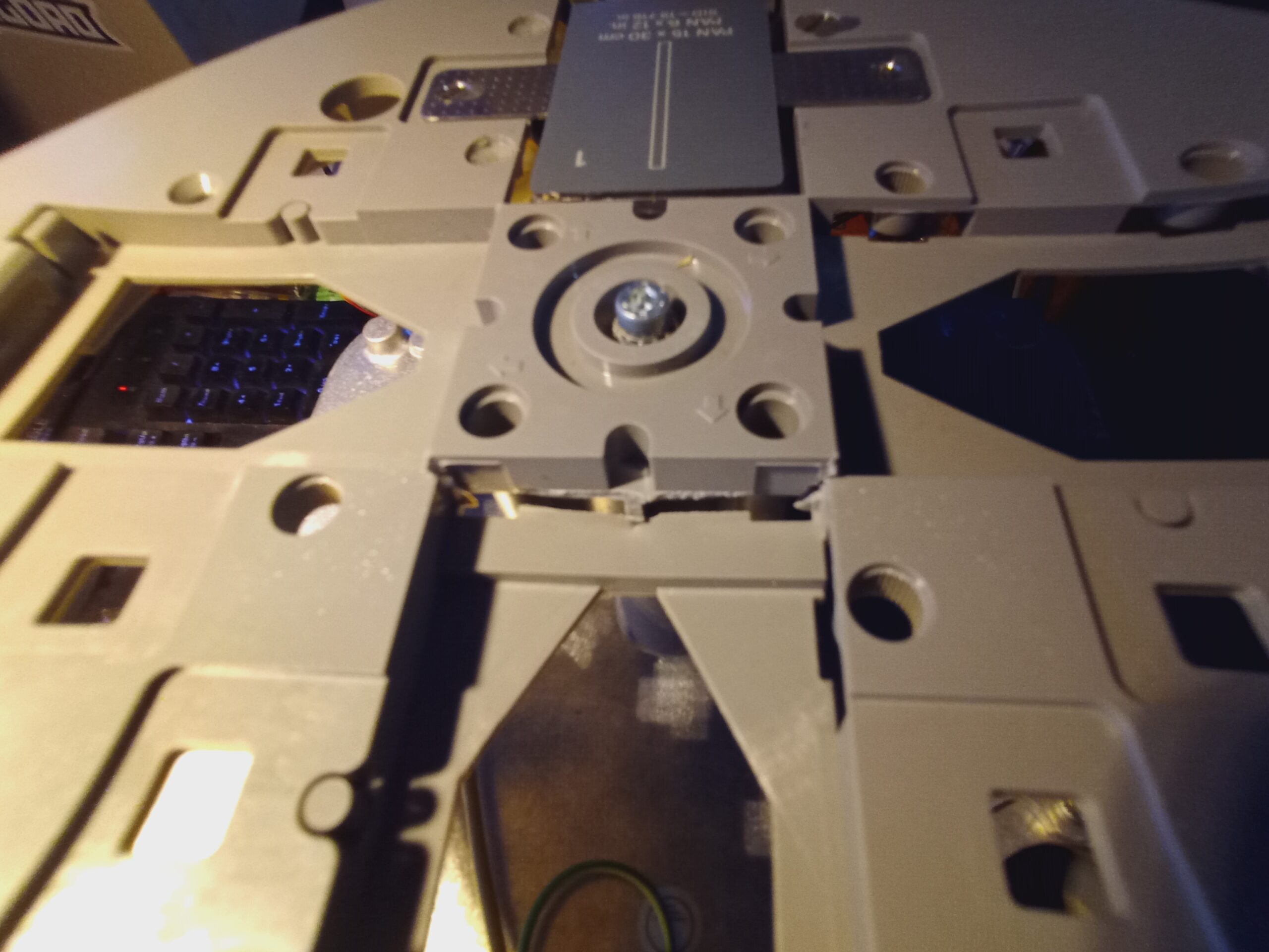
On the front of the head is the filter carousel. In this case it’s only fitted with a 2.5mm Aluminium filter. These are used to filter out the low-energy X-Rays from the beam, reducing the overall dose to the patient of radiation that does not contribute to the resulting image, as these lower energy rays are totally absorbed.
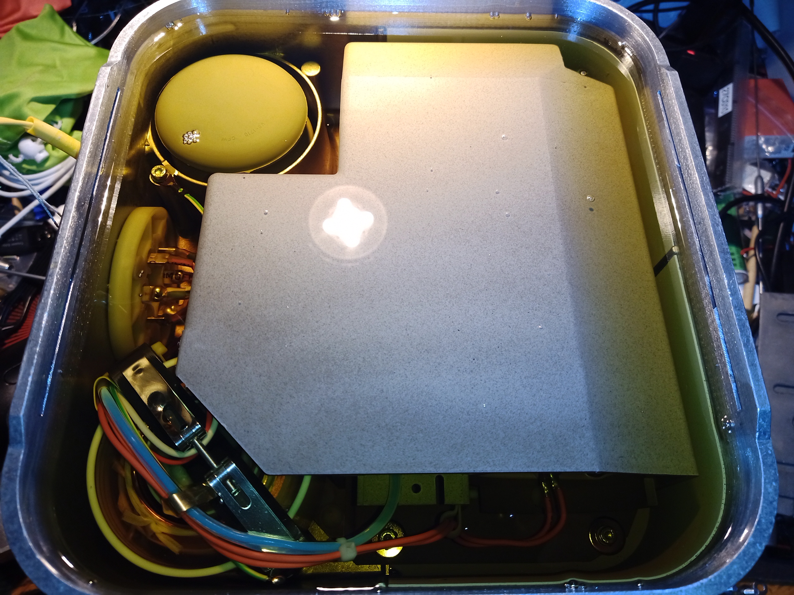
Removing a lot of cap screws later & the O-Ring sealed cover comes off the head. Unsurprisingly, this is full of dielectric mineral oil for insulation & cooling. There’s not much to see yet, as most of the components are hidden inside the plastic housings. The expansion bellows is at the top left, and the main HV transformer bottom left.
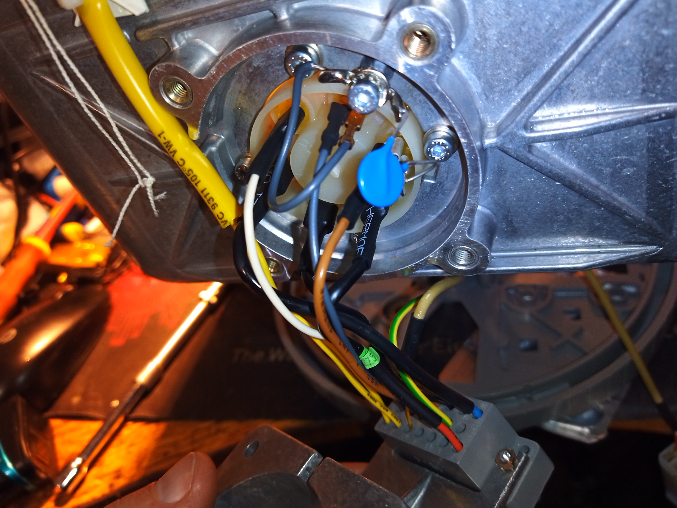
All the wiring to the head is fed through this plastic plug in the side, which is O-Ring sealed into the casting to prevent oil leaking out.
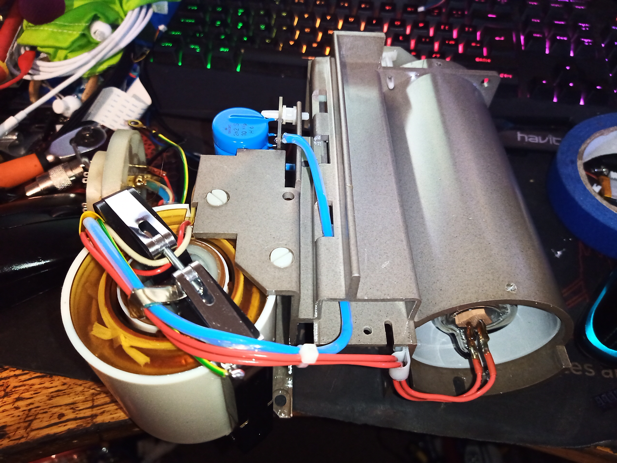
A clean bottle, syringe & some oily mess later, I manage to get the core out of the housing. This unit had about 3L of oil! The main HV transformer is hanging off the lower left corner of the plastic frame here, with the rest of the PSU behind it. The X-Ray tube is hiding within a metal shield in the tube to the right. There are no primary drive components present in the head – all of that is in the rest of the X-Ray machine.
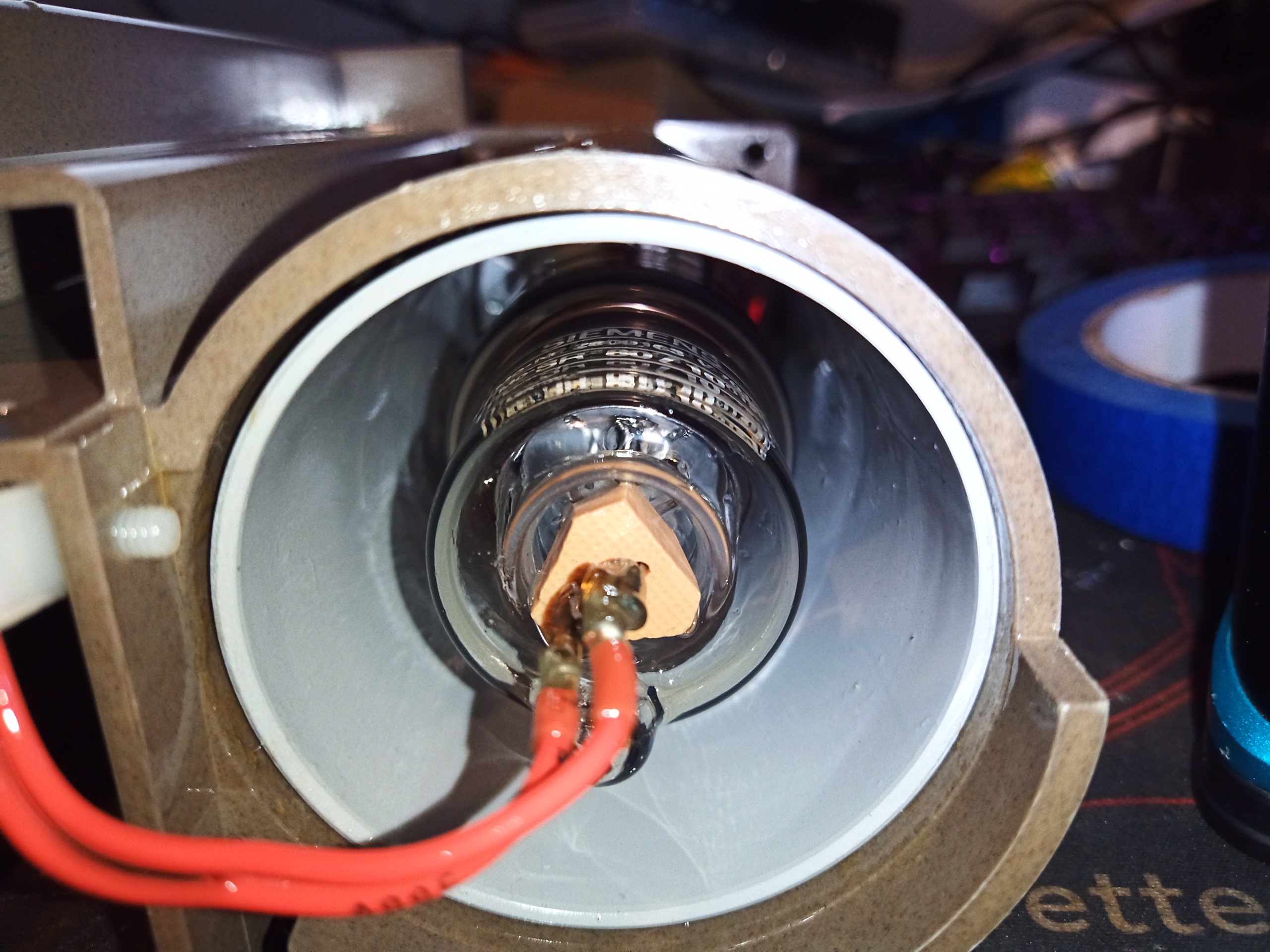
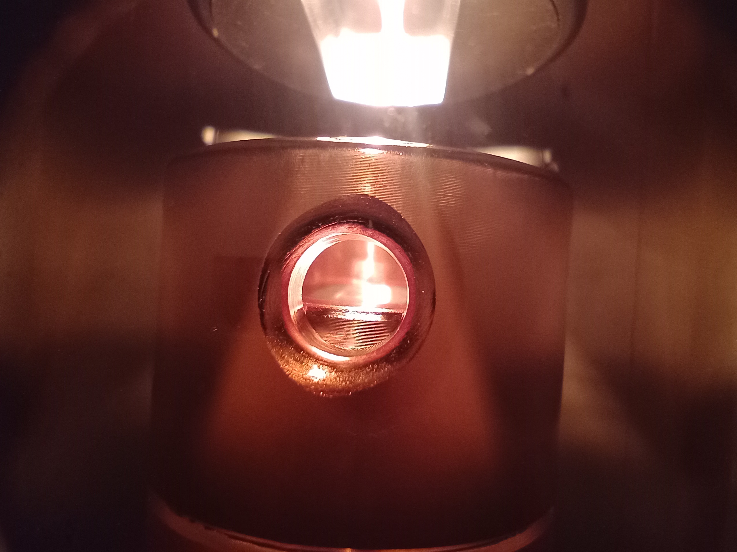
A look down filament end of the X-Ray tube. There’s a shield around this, likely to help stop stray X-Rays, and to provide some electric field strength distribution, as this is connected to centre of the HV PSU’s voltage multiplier, biasing it at around +40kV.
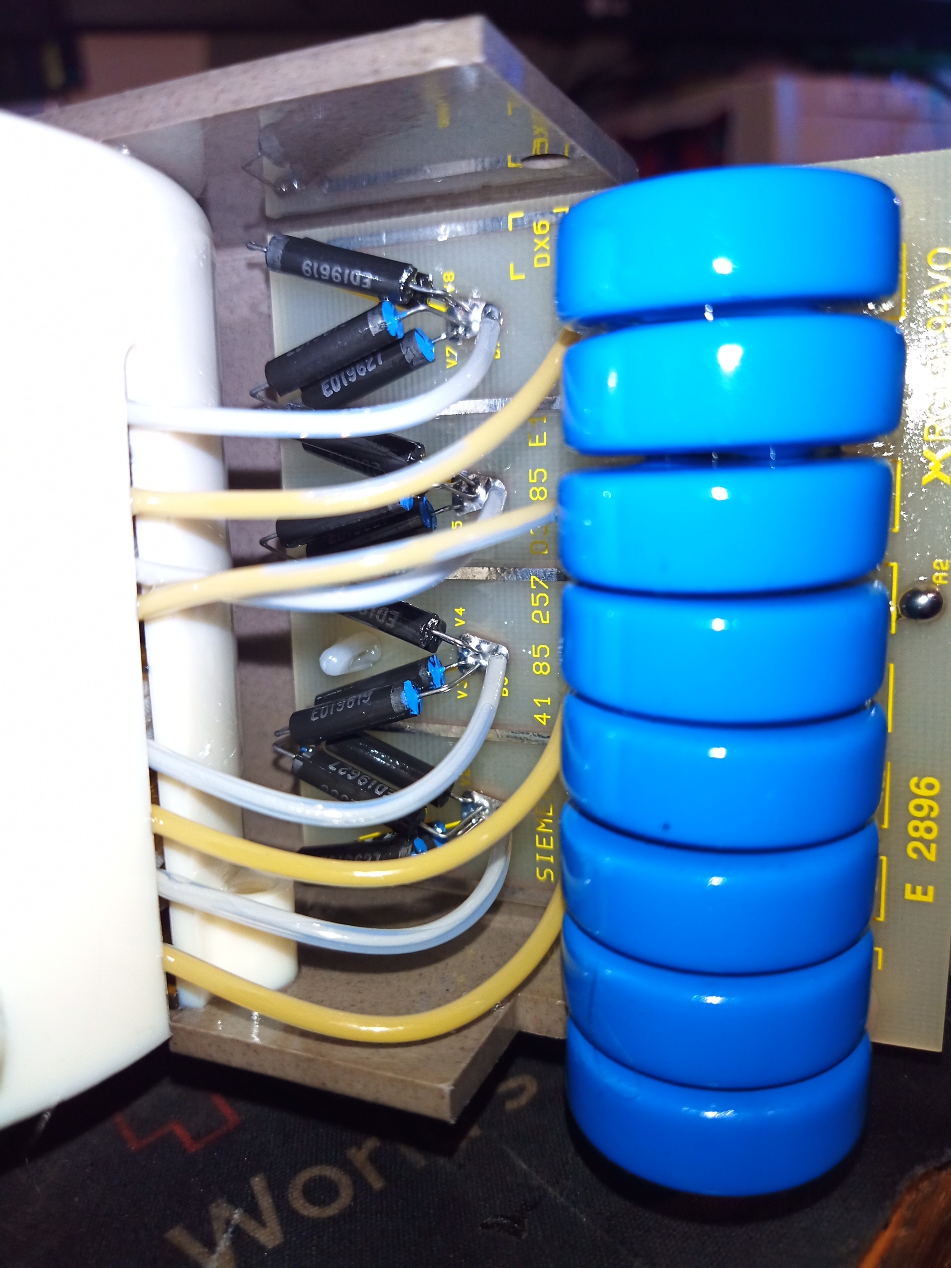
Behind the transformer lies the rest of the PSU – a 4-stage voltage multiplier. There are 4 separate secondary windings on the transformer, each feeding a voltage doubler. This is to keep the high-voltage stress on the transformer windings to a minimum, as the windings themselves only see 10kV per section, instead of the full output voltage of 80kV. This is increased to 20kV per section by the full-wave doubler, and as these are all in series the output end has the full 80kV.
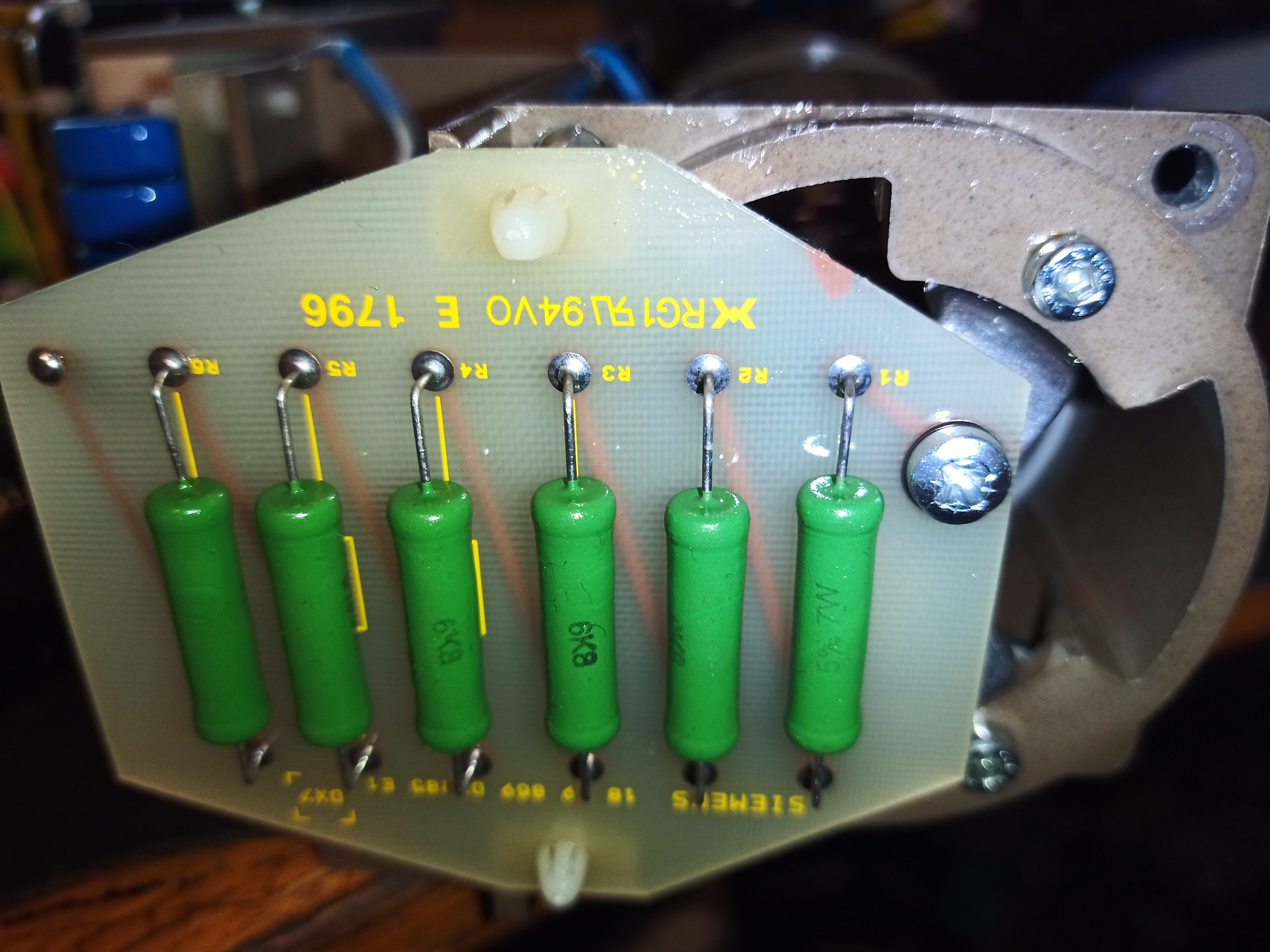
Over at the anode end of the X-Ray tube, is this board with 6x 6.8kΩ resistors in a series string for 40.8kΩ total. As this is in series with the tube anode, I presume it’s there for current limiting. At full power of 80kV 10mA, this stack will be dropping almost 500v & 4W of power.
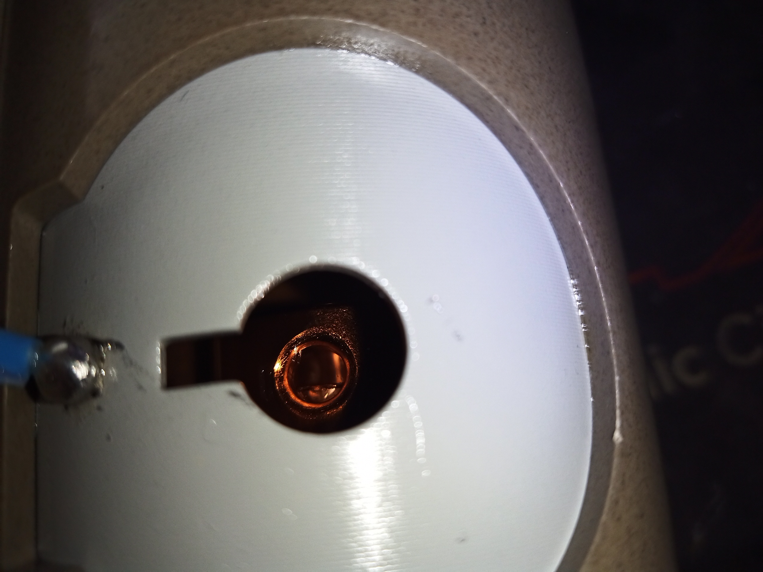
At the bottom of the unit is the aperture where the X-Rays emerge. The connection to the centre of the voltage multiplier is also visible here.
Here is the view through the side of the tube with the filament powered at 4v. Filament current is about 2.6A. The copper heatsink block surrounding the Tungsten target is visible in the centre of the picture. The target is probably alloyed with Rhenium to give better longevity.
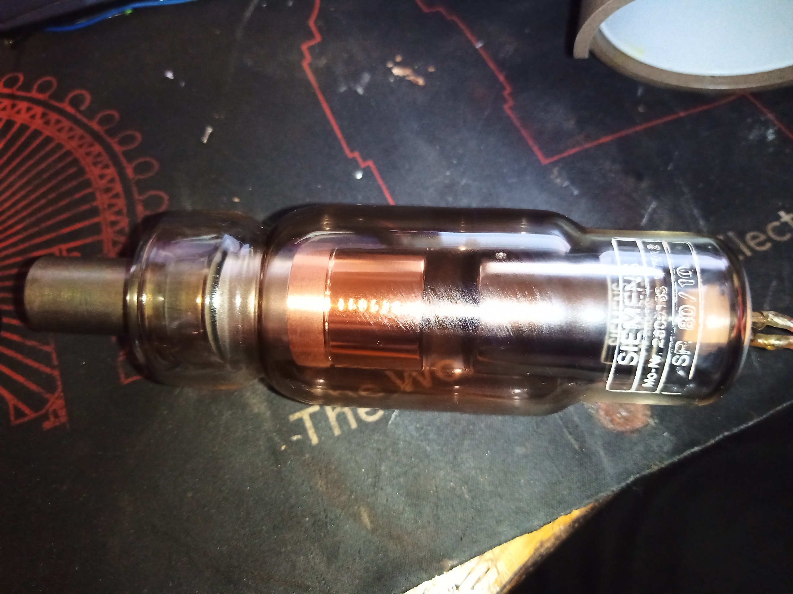
The tube is held into the frame by a single bolt in the middle of the anode spider. Removing this bolt allows the tube to come out, and it’s heavy. This is not that surprising, since the anode of the tube is a solid chunk of Tungsten & copper!
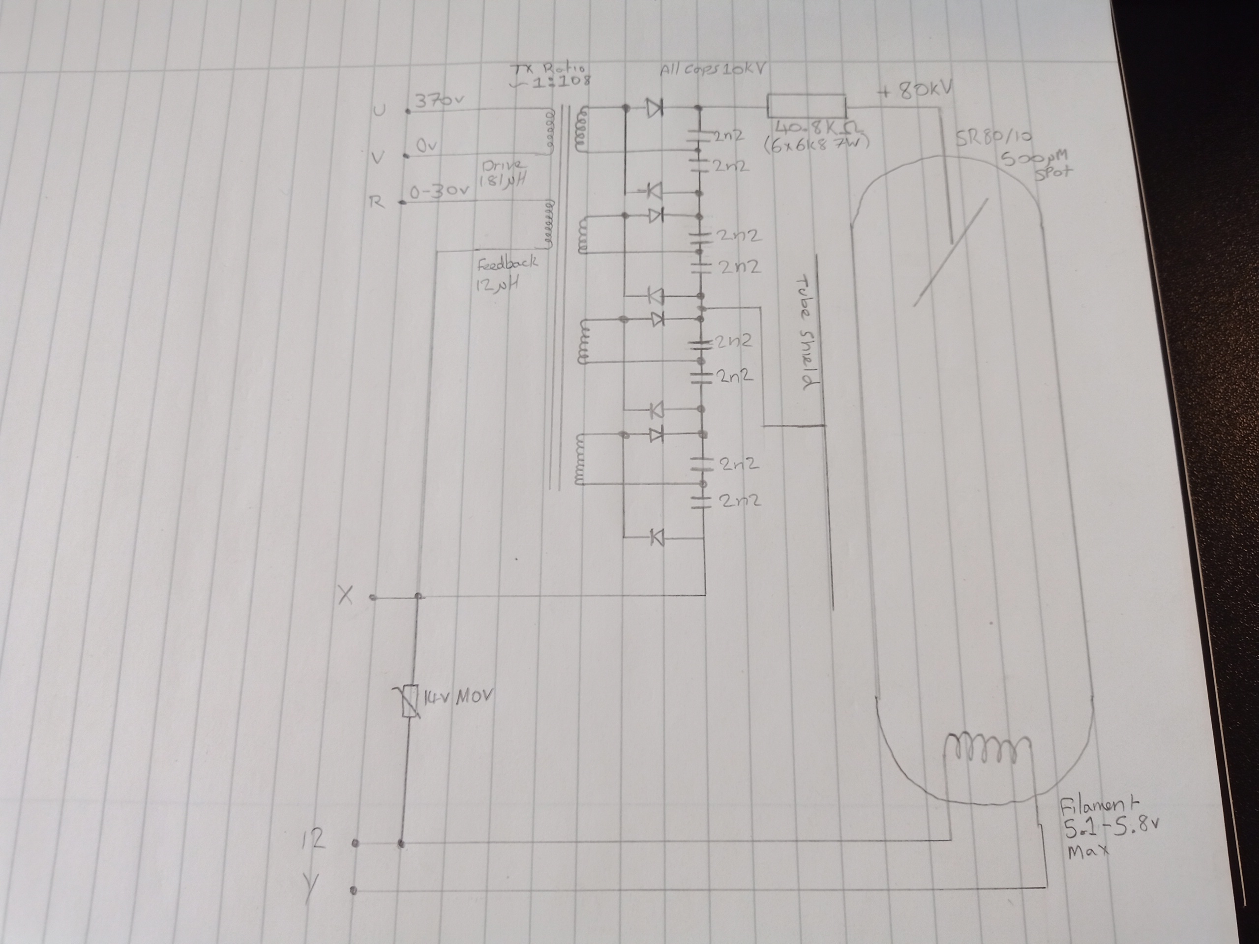
Finally, here is the internal schematic of the head itself, with the pinout marked. The operating frequency of the transformer is 35kHz, and it is my understanding that these are operated in resonant mode. There’s no filament transformer, the drive for this is supplied externally. Output voltage feedback is via an auxiliary winding on the transformer.
