IPL hair removal is rather similar to laser hair removal – high energy photons are directed into the hair follicle to heat the cells up until death occurs, stopping the hair from growing. These units use high-energy Xenon flash tubes to do the job, and operate in exactly the same fashion as a camera flash. Here are the internals of such a device.
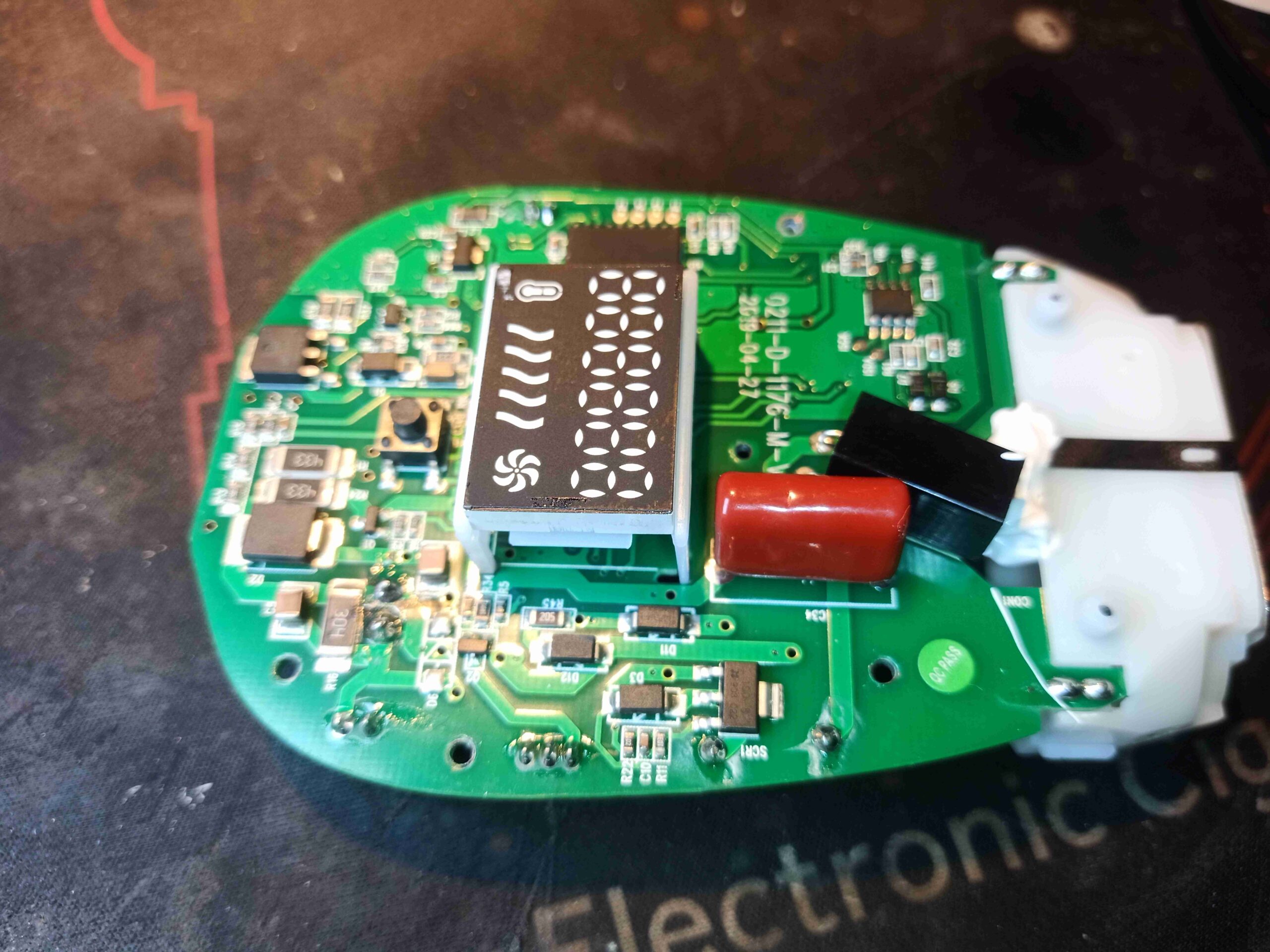
The mainboard in the top of the unit deals with all the functions of the device. There’s a main microcontroller, which in this case is an unmarked IC. The UI is a simple LED display, showing the number of shots on the tube remaining. These units come with 500,000 shots programmed in. The limit is to prevent the Xenon tube from exploding when it reaches end of life. In the case of these devices, after the counter reaches zero, the unit is disposed of. The trigger transformer is visible at the right of the board, along with it’s capacitor. This is triggered by a small Thyristor at the bottom edge of the board just to the right of the LED display. There are some power handling components on the left side, along with the main switching FET & gate drive IC for the high voltage supply.
There are several power settings, and the power itself is varied by the voltage on the main capacitor, from around 270v to 400v. There’s no dedicated switching IC here – The microcontroller generates a 65kHz square wave, from 0-50% duty cycle to drive the main switching FET. There’s a resistive feedback network to regulate the boost converter’s output voltage.
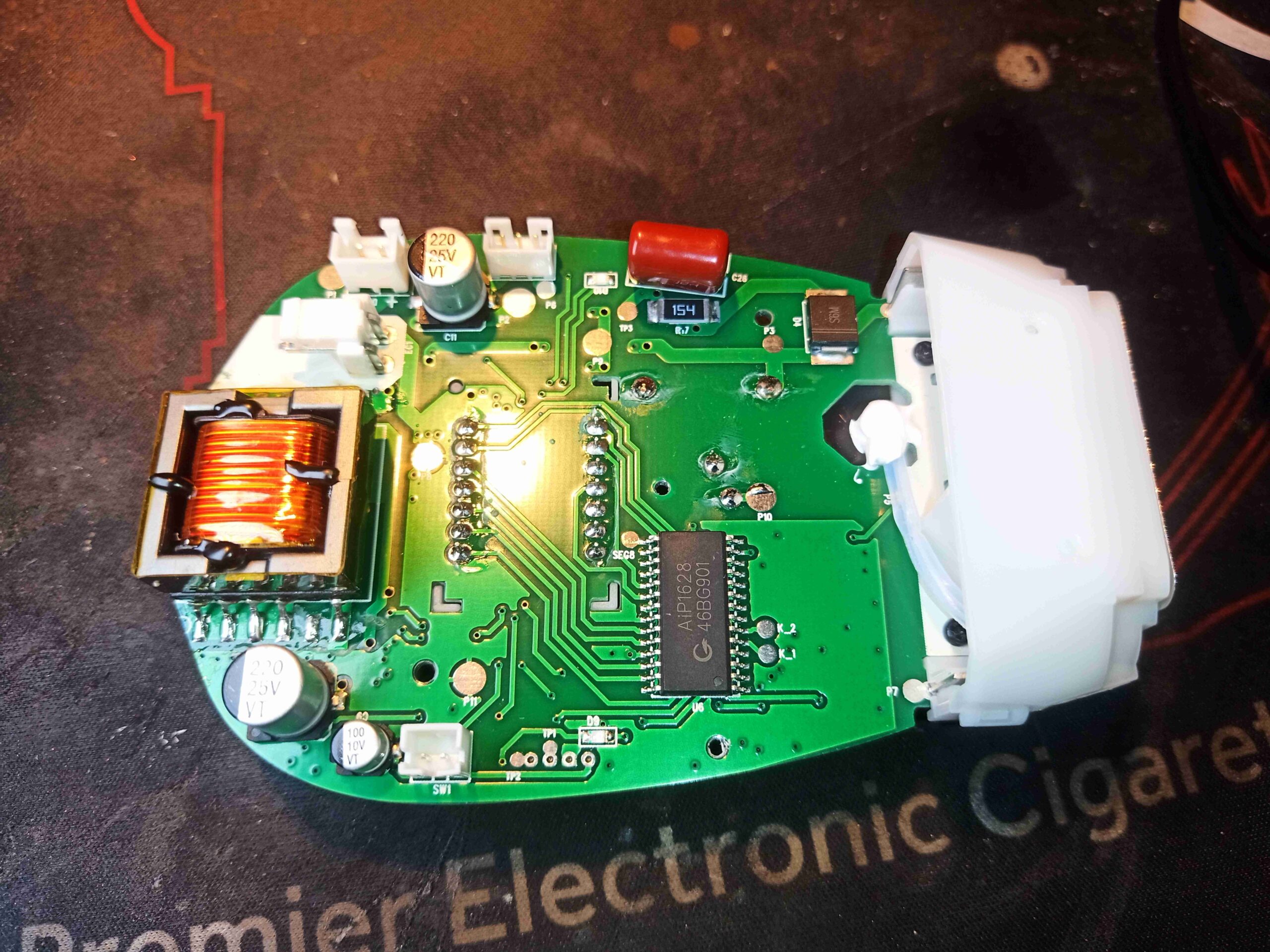
There’s less on the bottom of the PCB, apart from the connections to the PSU, cooling fan, capacitor & trigger button, there is the transformer for the HV supply. At the lower centre, is the driver IC for the LED display.
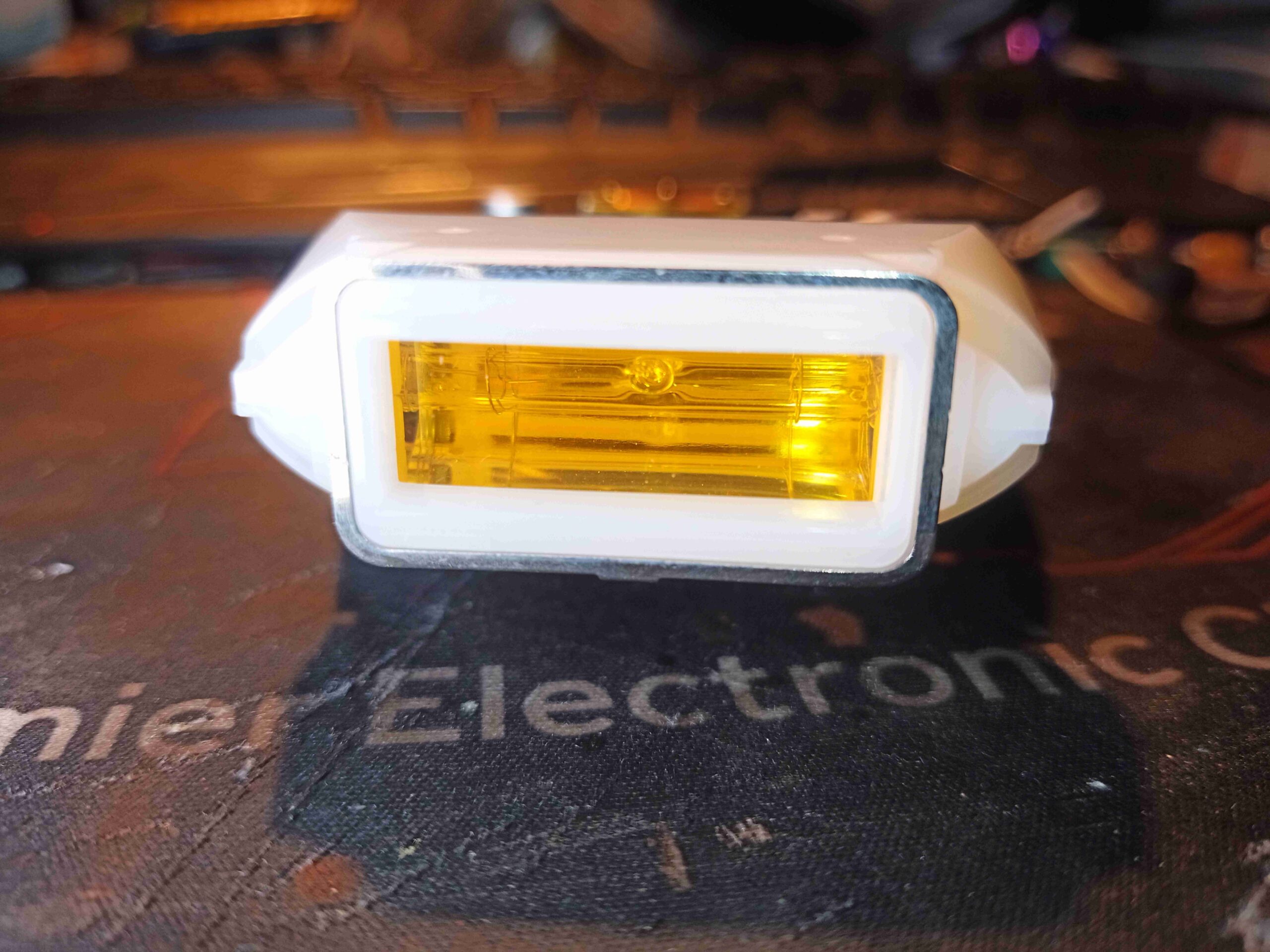
The flash tube is mostly hidden inside a plastic shroud with an amber filter glass on the front to provide the correct light spectrum. The metal ring around the outside edge is part of a capacitive detection mechanism that prevents the tube firing unless it’s placed against skin. I have no doubt that the intensity of light from these devices could quite easily cause eye damage. Even absorbing the energy into the skin is slightly painful – hitting black tattoo ink with it feels like a needle prick!
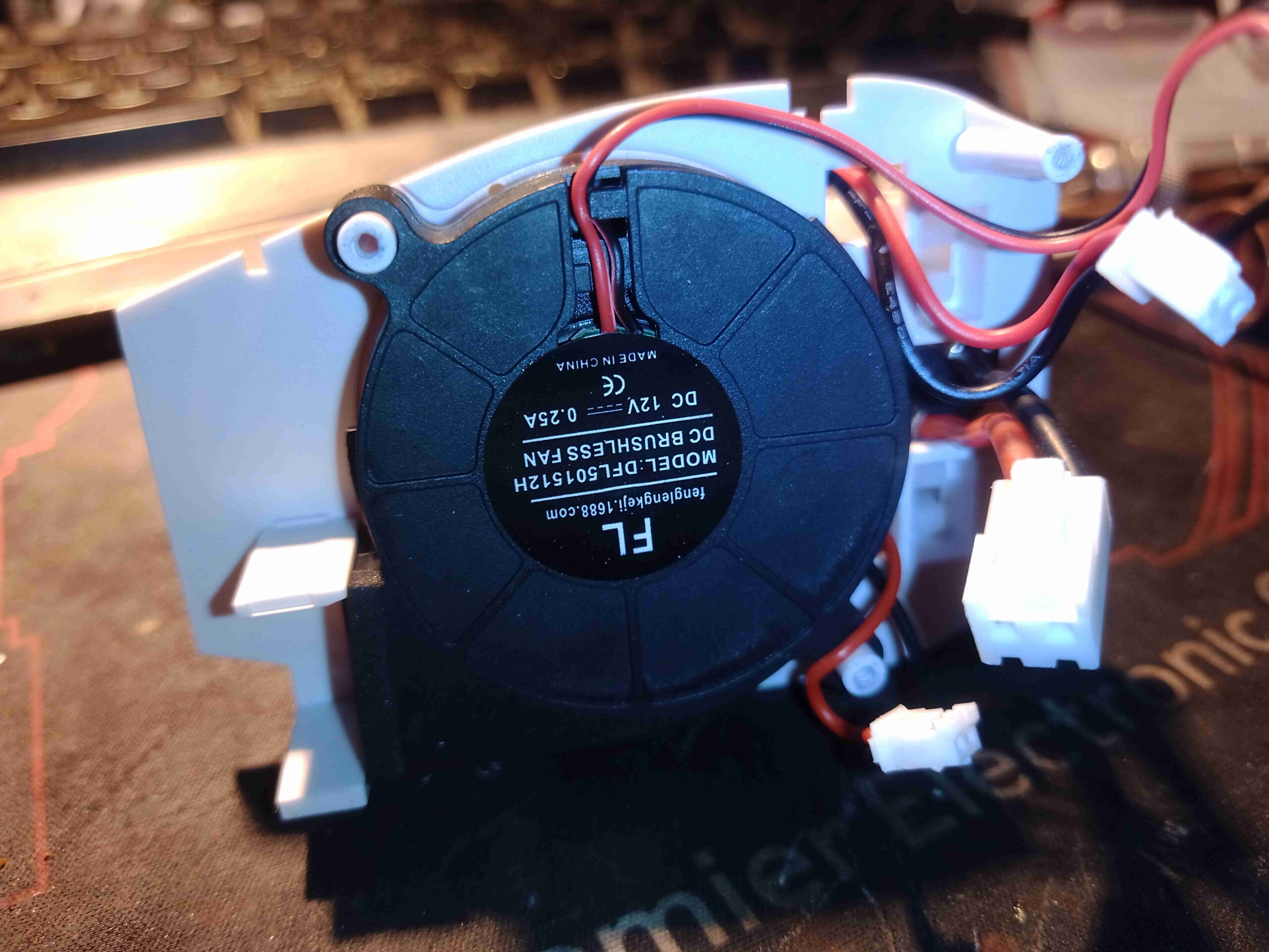
Since the flash tube passes such a large pulse of energy, it is force cooled by this small blower which sits under the mainboard, and directs air into a slot in one end of the tube housing. The other end allows the air to exhaust back out, taking the heat with it. This fan runs continually while the device is powered on. This fan shifts an impressive amount of air for it’s size.
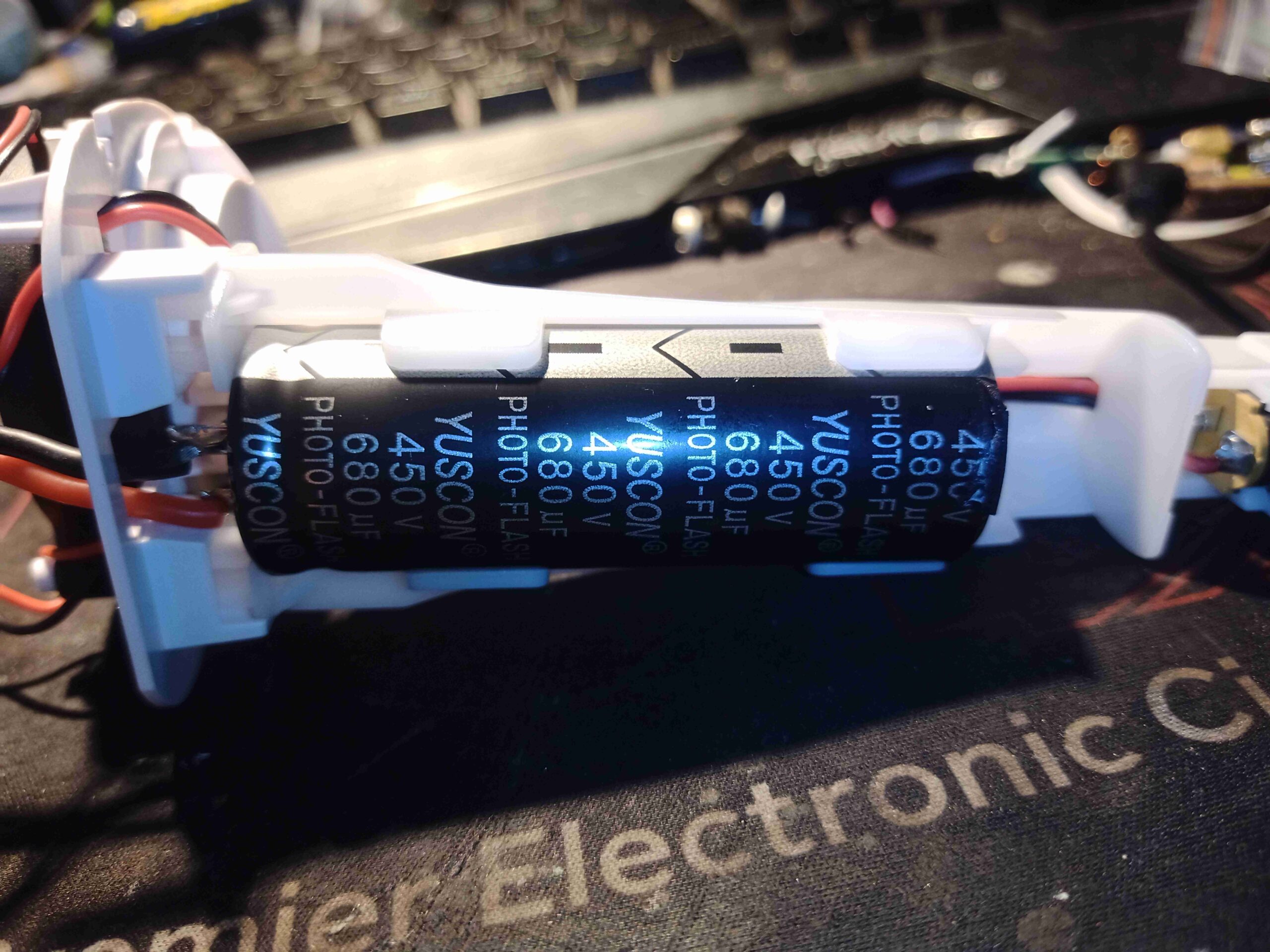
Finally, there is the main storage capacitor for the flash tube. This sits down in the handle, and is massive at 450v 680µF, providing 69 Joules of energy at full charge. In the case of this unit, the energy is variable from 25-55J.

Very interesting!
Thanks for the teardown.
I was wondering – how did you get it open? Did you split the sides first, or pull off the endcap where the flash tube is?
I want to remove the filter to use this as a flash in long exposures, and it’d be all yellow!
End cap first if I recall correctly!