Posted on Leave a comment

OLED Pulse Oximeter Teardown

OLED Pulse Oximeter
OLED Pulse Oximeter

Here’s a piece of medical equipment that in recent years has become extremely cheap, – a Pulse Oximeter, used to determine the oxygen saturation in the blood. These can be had on eBay for less than £15.

Powered On
Powered On

This one has a dual colour OLED display, a single button for powering on & adjusting a few settings. These cheap Oximeters do have a bit of a cheap plastic feel to them, but they do seem to work pretty well.

Pulse Oximeter
Pulse Oximeter

After a few seconds of being applied to a finger, the unit gives readings that apparently confirm that I’m alive at least. 😉 The device takes a few seconds to get a baseline reading & calibrate the sensor levels.

Main PCB Top
Main PCB Top

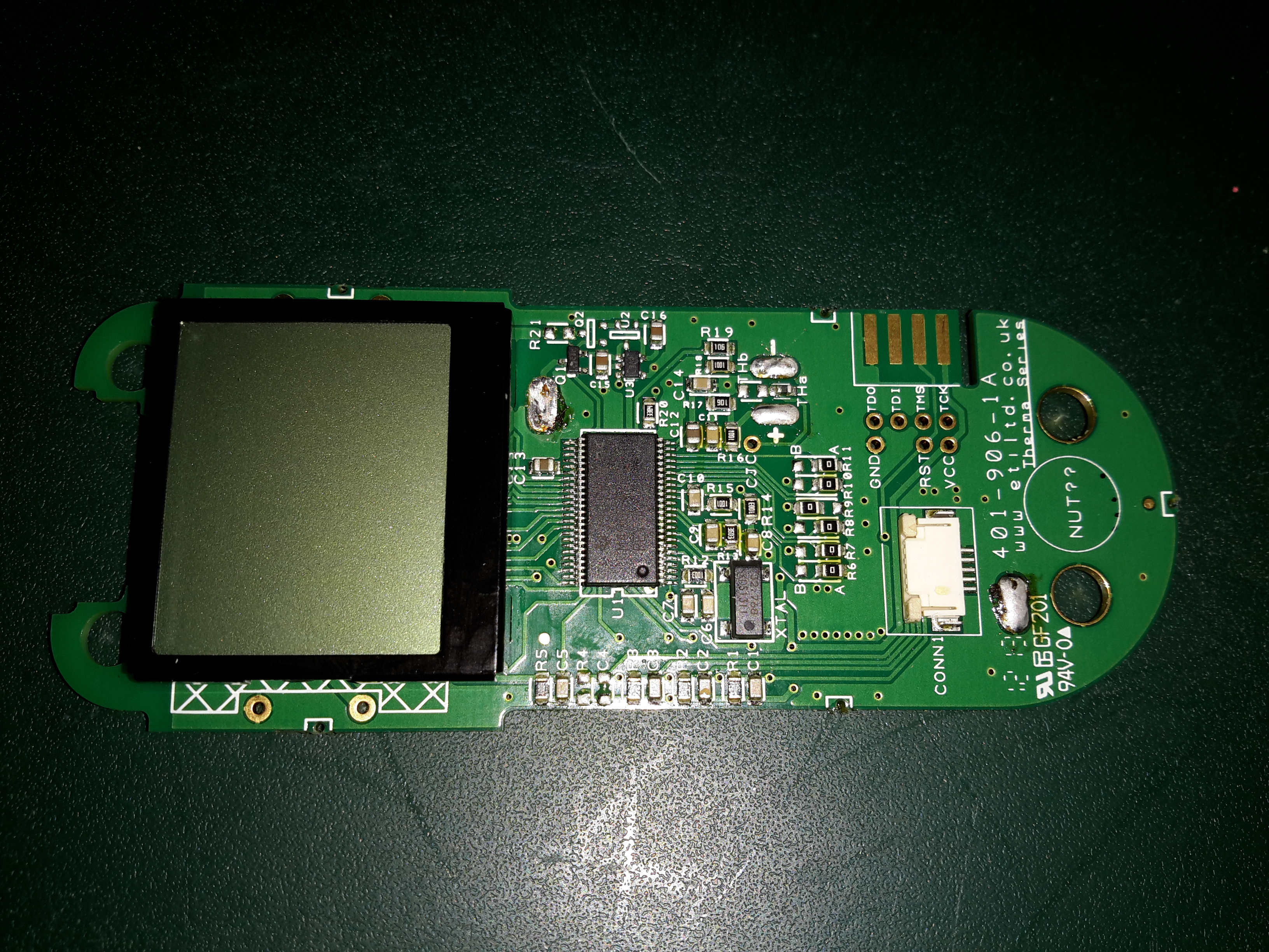
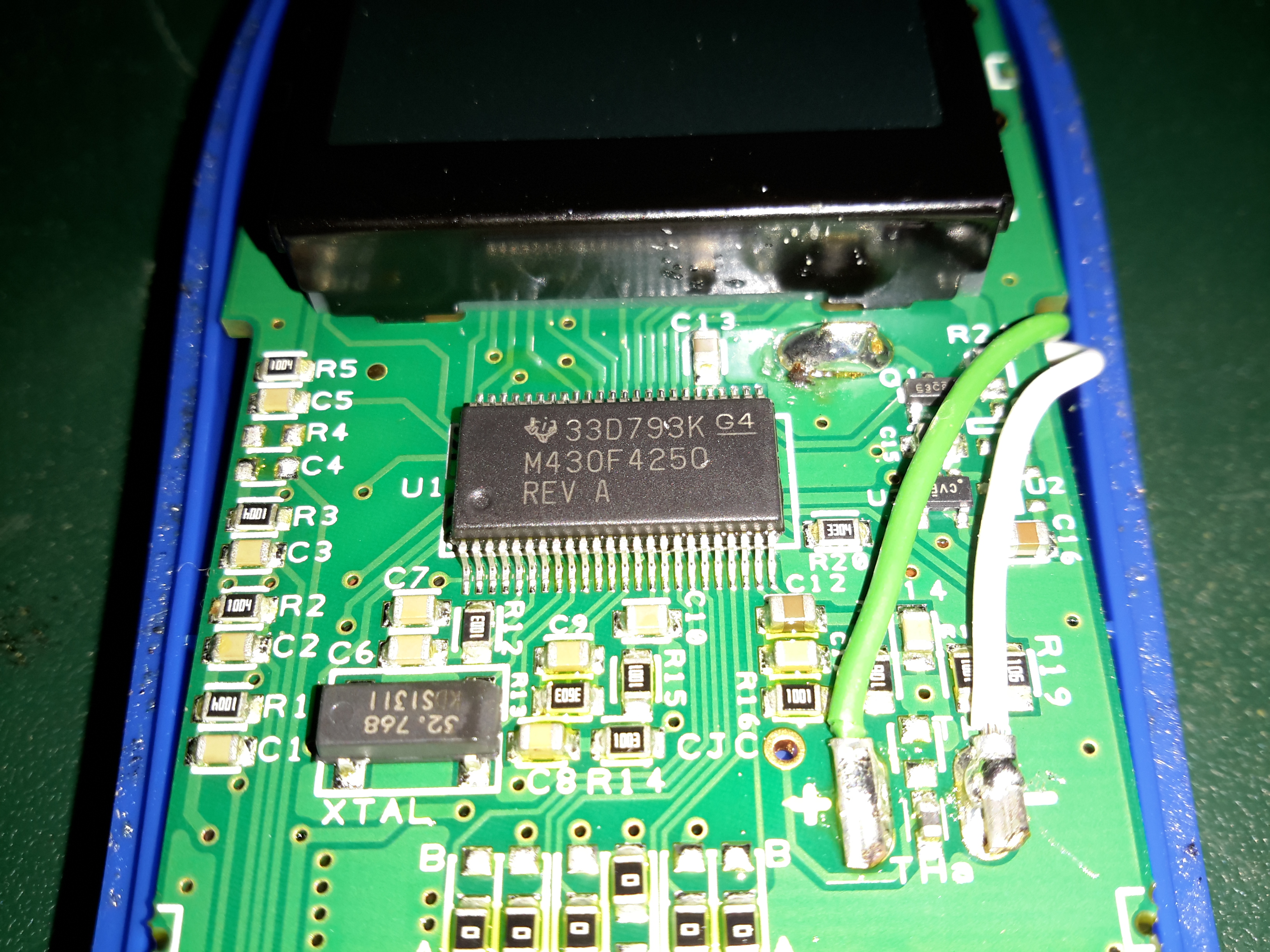
The plastic casing is held together with a few very small screws, but comes apart easily. here is the top of the main board with the OLED display panel. There appears to be a programming header & a serial port on the board as well. I’ll have to poke at these pads with a scope to see if any useful data is on the pins.

Main PCB Bottom
Main PCB Bottom

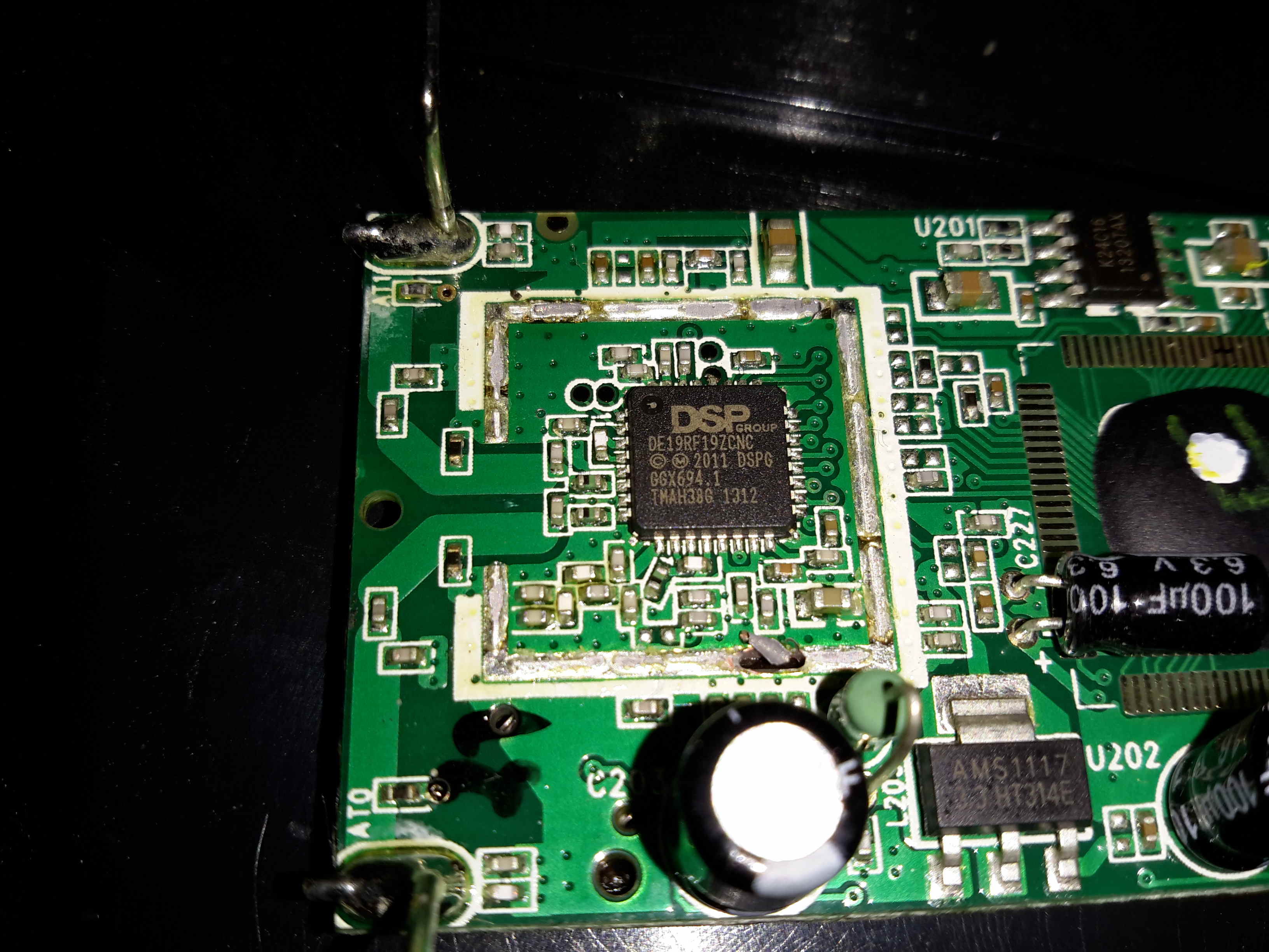
The bottom of the board has all the main components of the system. The microcontroller is a STM32F03C8T6, these are very common in Chinese gear these days. There’s a small piezo beeper & the main photodiode detector is in the centre.
There is an unpopulated IC space on the board with room for support components. I suspect this would be for a Bluetooth radio, as there’s a space at the bottom left of the PCB with no copper planes – this looks like an antenna mounting point. (The serial port on the pads is probably routed here, for remote monitoring).
At the top left are a pair of SGM3005 Dual SPDT analogue switches. These will be used to alternate the red & IR LEDs on the other side of the shell.
A 4-core FFC goes off to the other side of the shell, bringing power from the battery & supplying the sensing LEDs.

Battery Compartment
Battery Compartment

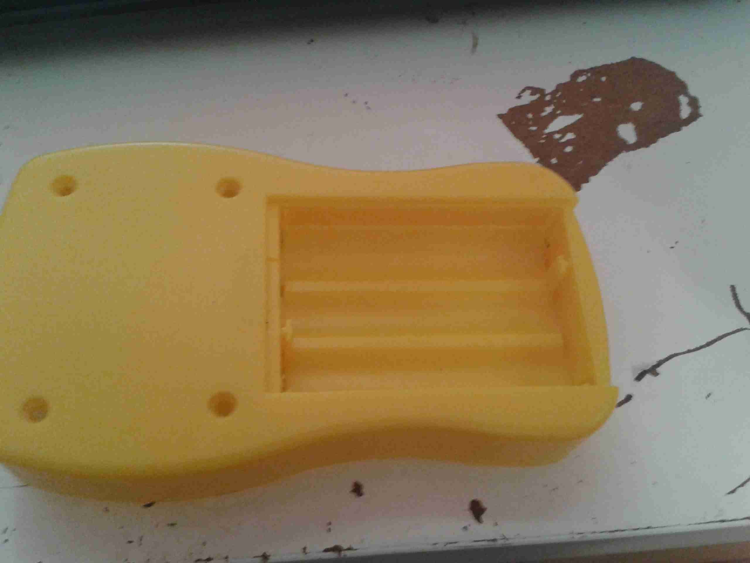
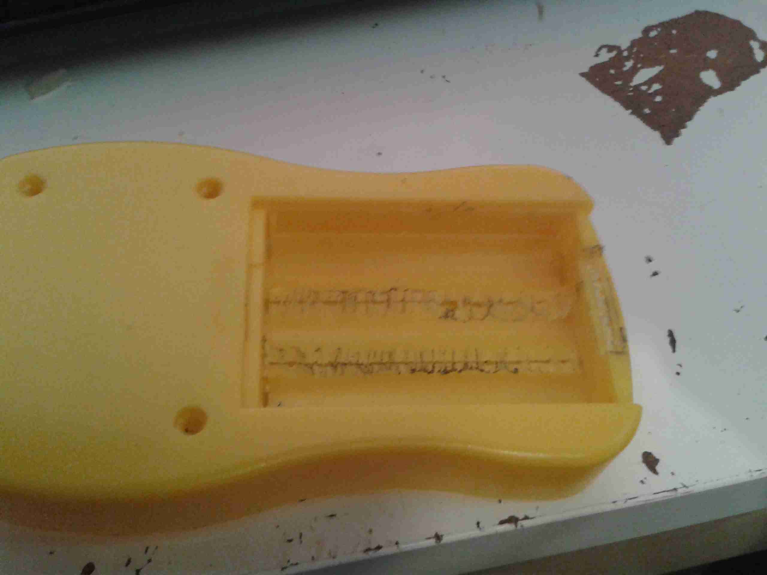
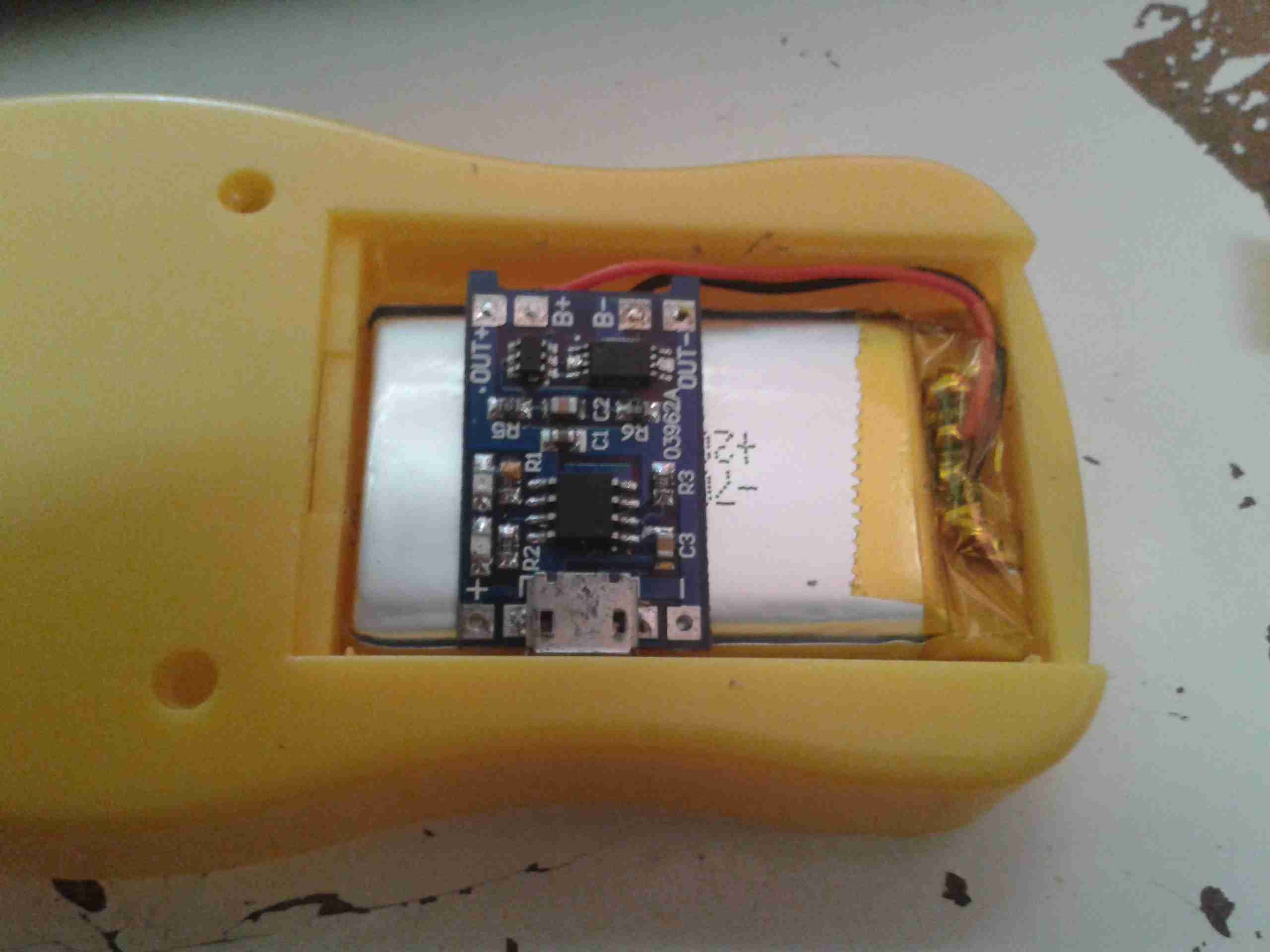
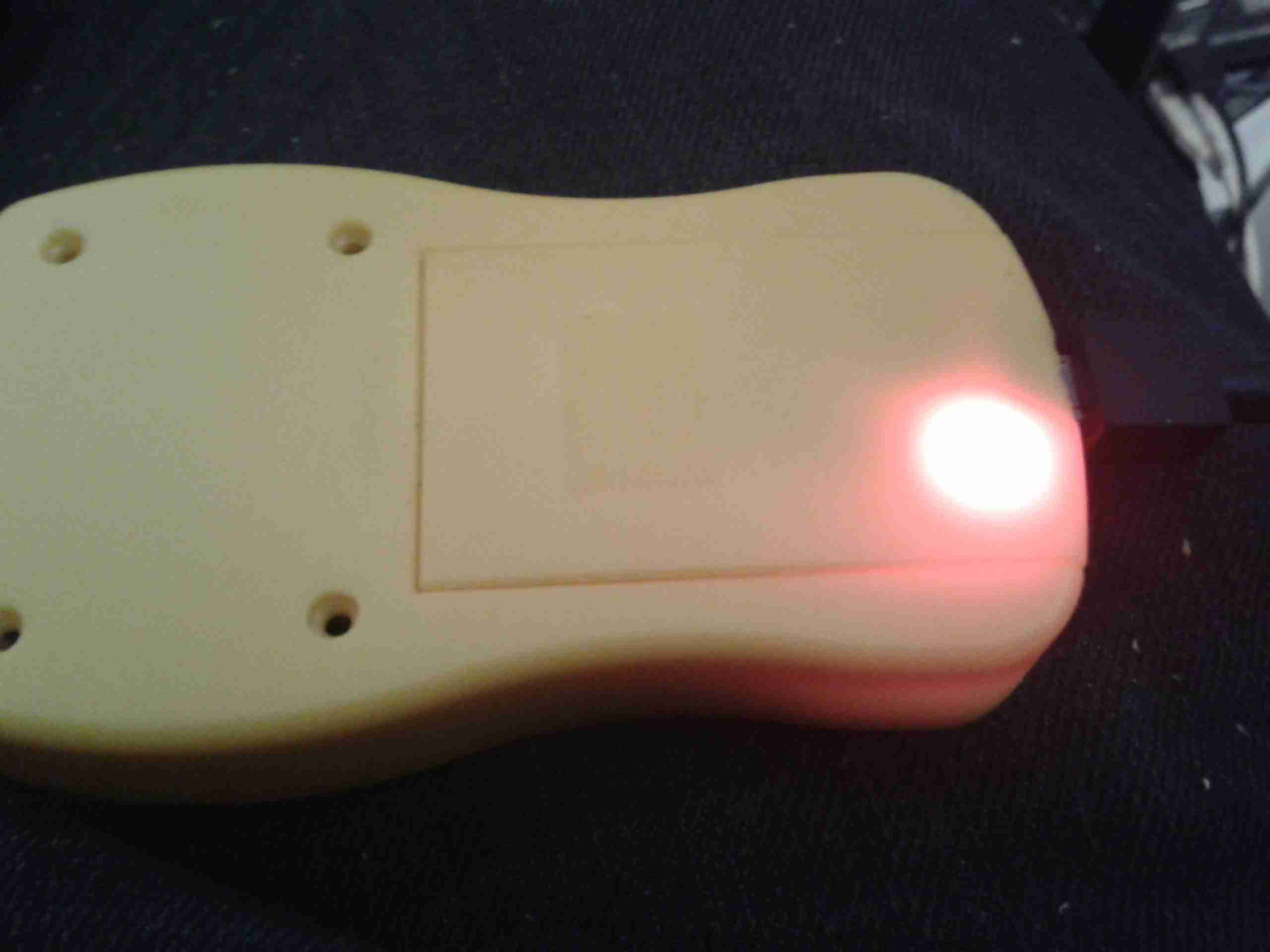
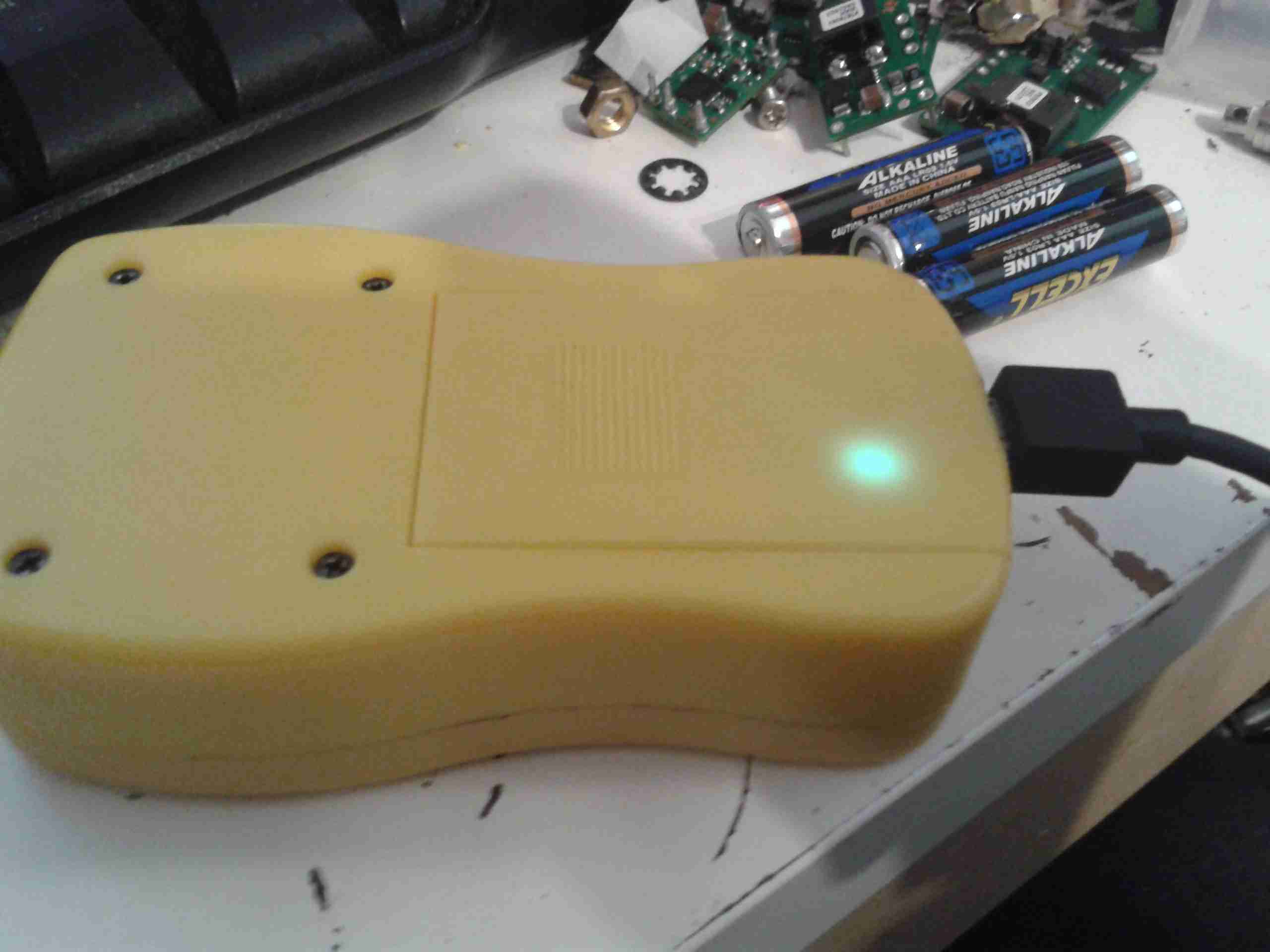
Power is supplied by a pair of AAA cells in the other shell.

Dual LED
Dual LED

The sensor LEDs are tucked in between the cells, this dual-diode package has a 660nm red LED & a 940nm IR LED.

Posted on Leave a comment

Motorola Cordless DECT Phone Teardown

Motorola DECT Phone
Motorola DECT Phone

Another random teardown from the junk box time!
Here’s an old Motorola DECT landline phone, no use to me as I’ve not used a landline for many years.

Battery Compartment
Battery Compartment

Not much on the back, other than the battery compartment for a pair of AAA rechargables. The base unit contains the charger.

Main PCB
Main PCB

Here’s the main PCB removed from it’s casing. There’s not really much going on, one of the main ICs, which is probably a microcontroller, is a COB device, so no part numbers from there. There’s a row of pads for programming the device at the factory. The RF section is on a dedicated IC, a DE19RF19ZCNC from DSP Group. I couldn’t find much on this part, but it’s one of a range of DECT/VoIP DSP devices.


Base Unit PCB
Base Unit PCB

Inside the base unit is a similar board, just without the keypad. Main microcontroller is again a COB device, the RF IC is under the shield.

Main Chipset
Main Chipset

Removing the shield reveals the same IC as in the handset, only this PCB has a pair of antennas.

Posted on Leave a comment

ETI Thermamite Catering Thermometer

Catering Thermometer

Here’s another bit of commercial gear, a catering thermometer. These are used to check the internal temperature of foods such as meat, to ensure they’re cooked through.

This was given to me with some damage, the battery cover is missing & the plastic casing itself is cracked.

Battery Compartment
Battery Compartment

Power is provided by 3 AAA cells, for 4.5v

Main PCB
Main PCB

There’s not much to these units, the large LCD at the top is driven by the IC in the centre. A programming header is also present on the board near the edge.

Microcontroller
Microcontroller

The core logic is taken care of with a Texas Instruments M430F4250 MSP430 Mixed-Signal Microcontroller. This MCU has onboard 16-bit Sigma-Delta A/D converter, 16-bit D/A converter & LCD driver. Clock is provided by a 32.768kHz crystal.
The probe itself is just a simple thermistor bonded into a stainless steel rod.

Posted on Leave a comment

GY561 Frequency & Power Meter LiPo Conversion

From the factory, the GY561 meter uses alkaline AAA cells for power. As these are not rechargable, and I don’t carry any other devices that take such batteries, I figured I’d replace them with a single Lithium Polymer cell that I can charge via USB.

Battery Compartment
Battery Compartment

Here’s the battery compartment, with the original spring terminals removed.
I searched eBay for a suitable sized cell, and settled on a 1000mAh type, with dimensions of 47mm x 28mm x 7mm.

This size cell required a small amount of modification to the battery compartment to make it fit properly with the associated charge & protection circuitry.

Modified Compartment

Here’s the modifications made to the compartment, I’ve ground away the plastic to make the bottom flat, and the plastic tabs that retained the original spring terminals.

Modifications
Modifications

After grinding away the original battery spring holders with a dremel, the cell fits perfectly in the available space. The small PCB on the top of the cell is the USB charger & protection.

Charger
Charger

The charger is located in a slot cut in the bottom of the casing, so the USB port is accessible from outside the compartment.

Wiring
Wiring

Here’s the rest of the wiring completed, with the power wires going through holes in the bottom of the battery compartment to join onto the PCB where the original terminals were located. I have insulated the solder joints on the control PCB with some Kapton tape to prevent any shorts against the lithium cell.

Battery Cover
Battery Cover

A small cutout was also required in the battery cover to allow the USB connector to poke out. This was easy to do on the soft plastic with a Dremel tool.

Charging Port
Charging Port

With the battery cover installed, the USB port is nicely recessed into the edge.

Charging LED
Charging LED

The indicator LEDs on the charging & control board show nicely through the plastic, here’s the unit on charge. When the charge is complete, another LED lights as shown below.

Charging Complete
Charging Complete
Posted on Leave a comment

Motorola V360v

Front
Front

Here is a more modern phone, the Motorola V360v. Features include Dual screens, 640×480 VGA camera, full col

our TFT Main LCD, SD-Micro slot.
Here on the back the grey scale LCD can be seen, with the camera lens to the right of the Motorola logo

Keypad
Keypad

Here the phone is opened showing the keypad & the full colour TFT LCD display.

Battery Compartment
Battery Compartment

Here the battery is removed from the unit, showing the SIM connector. The antenna cover is still on at the bottom.

Antenna
Antenna

The antenna cover has been removed in this shot, the antenna is the white section at the bottom, With the loudspeaker & the external antenna connector hidden at the right.

PCB
PCB

Here is the main PCB. Parts from left are the Bluetooth module at the top, supplied by Broadcom, the SD Card socket at the bottom. Main CPU next to that is the Freescale SC29343VKP. Above right of the CPU is the Freescale SC13890P23A Charger, Power & Audio IC. Below is the SIM card socket. Under the main CPU is the Intel Flash memory IC. ICs inside the shields are the RF sections for transmit & receive.

Cover Removed
Cover Removed

Rear of the display unit showing the monochrome LCD. The camera module on the bottom left. Ear speaker on the far right of the unit.

Main LCD
Main LCD

Main colour TFT LCD.

Camera
Camera

Camera module removed from the LCD unit.

Vibra-Motor
Vibra-Motor

The vibration motor attached to one of the LCD looms.

Posted on Leave a comment

HP Photosmart 375

Top
Top

This is a HP PhotoSmart 375 portable photo printer. With built in card reader, screen & PictBridge.
Top of the printer showing the UI Buttons & Screen.

Front
Front

Front of the unit, card reader slots at the top, Pictbridge USB connector at top left. Paper out slot at bottom. Cartridge door is on the right.

Cartridge Door
Cartridge Door

Here the cartridge door is open. Takes HP 95 Tri-Colour Inkjet Cartridge.

Battery Compartment
Battery Compartment

Battery compartment on the bottom of the unit. A Li-Ion battery pack can be installed here for mobile photo printing.

Bottom Label
Bottom Label

Specifications label.

USB + Power
USB + Power

Power adaptor & USB connection for PC use.

Paper Tray
Paper Tray

Rear door opened. Showing the paper feed tray.

Paper Feeder
Paper Feeder

Rear door has been removed in this shot. Paper feed roller & platen roller can be seen here.

Rear Cover Paper Feeder

Paper holder attached to rear door.

Top Cover
Top Cover

Bottom of the top cover, with connections for the buttons & LCD panel.

Main PCB
Main PCB

This is the main PCB of the unit. Controls all aspects of the printer. CPU in center, card reader sockets are along bottom edge. various support circuitry surrounds the CPU.

Rear
Rear

Rear shell has been removed here. Showing the main frame & the carriage drive motor on the left.

Carriage Drive
Carriage Drive

Closeup of the carriage drive motor & timing belt system. All the motors in this printer are DC servo motors, not steppers.

Main Drive Motor
Main Drive Motor

Main drive motor, feeds paper, drives rollers, operates cleaning mechanism for the inkjets.

Shaft Encoder
Shaft Encoder

Mainshaft encoder. Main drive motor is bottom right hand side with timing belt drive.

CPU
CPU

Closeup of the CPU. This is a Phillips ARM chip, unknown spec.

Card Reader Sockets
Card Reader Sockets

Detail of the card reader sockets, this unit takes all current types of Flash memory card.

HP 95 Tri-color Inkjet Print Cartridge