![Top Top](http://www.experimental-engineering.co.uk/wp-content/uploads/2010/08/04082010036-300x225.jpg)
This is a HP PhotoSmart 375 portable photo printer. With built in card reader, screen & PictBridge.
Top of the printer showing the UI Buttons & Screen.
![Front Front](http://www.experimental-engineering.co.uk/wp-content/uploads/2010/08/04082010037-300x225.jpg)
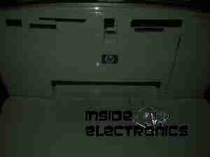
Front of the unit, card reader slots at the top, Pictbridge USB connector at top left. Paper out slot at bottom. Cartridge door is on the right.
![Cartridge Door Cartridge Door](http://www.experimental-engineering.co.uk/wp-content/uploads/2010/08/04082010038-300x225.jpg)
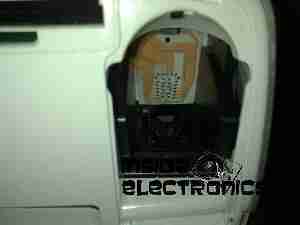
Here the cartridge door is open. Takes HP 95 Tri-Colour Inkjet Cartridge.
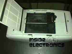
![Battery Compartment Battery Compartment](http://www.experimental-engineering.co.uk/wp-content/uploads/2010/08/04082010039-300x225.jpg)
Battery compartment on the bottom of the unit. A Li-Ion battery pack can be installed here for mobile photo printing.
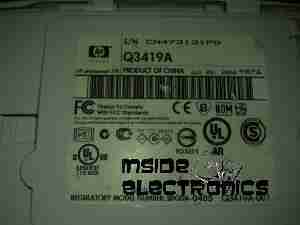
![Bottom Label Bottom Label](http://www.experimental-engineering.co.uk/wp-content/uploads/2010/08/04082010040-300x225.jpg)
Specifications label.
![USB + Power USB + Power](http://www.experimental-engineering.co.uk/wp-content/uploads/2010/08/04082010041-300x225.jpg)
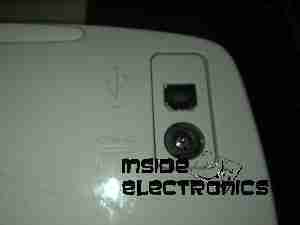
Power adaptor & USB connection for PC use.
![Paper Tray Paper Tray](http://www.experimental-engineering.co.uk/wp-content/uploads/2010/08/04082010042-300x225.jpg)
Rear door opened. Showing the paper feed tray.
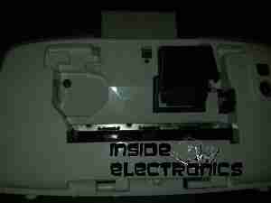
![Paper Feeder Paper Feeder](http://www.experimental-engineering.co.uk/wp-content/uploads/2010/08/04082010043-300x225.jpg)
Rear door has been removed in this shot. Paper feed roller & platen roller can be seen here.
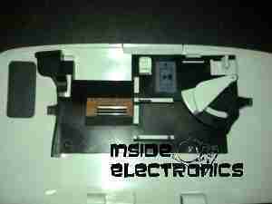
![Rear Cover Paper Feeder Rear Cover Paper Feeder](http://www.experimental-engineering.co.uk/wp-content/uploads/2010/08/04082010044-300x225.jpg)
Paper holder attached to rear door.
![Top Cover Top Cover](http://www.experimental-engineering.co.uk/wp-content/uploads/2010/08/04082010045-300x225.jpg)
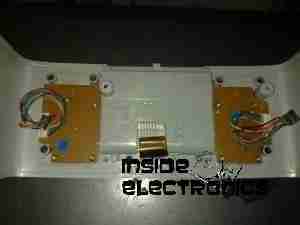
Bottom of the top cover, with connections for the buttons & LCD panel.
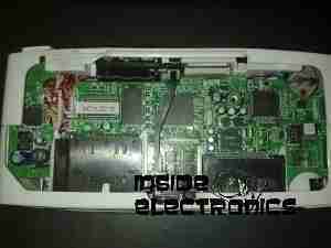
![Main PCB Main PCB](http://www.experimental-engineering.co.uk/wp-content/uploads/2010/08/04082010046-300x225.jpg)
This is the main PCB of the unit. Controls all aspects of the printer. CPU in center, card reader sockets are along bottom edge. various support circuitry surrounds the CPU.
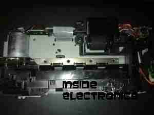
![Rear Rear](http://www.experimental-engineering.co.uk/wp-content/uploads/2010/08/04082010047-300x225.jpg)
Rear shell has been removed here. Showing the main frame & the carriage drive motor on the left.
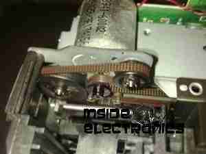
![Carriage Drive Carriage Drive](http://www.experimental-engineering.co.uk/wp-content/uploads/2010/08/04082010048-300x225.jpg)
Closeup of the carriage drive motor & timing belt system. All the motors in this printer are DC servo motors, not steppers.
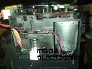
![Main Drive Motor Main Drive Motor](http://www.experimental-engineering.co.uk/wp-content/uploads/2010/08/04082010051-300x225.jpg)
Main drive motor, feeds paper, drives rollers, operates cleaning mechanism for the inkjets.
![Shaft Encoder Shaft Encoder](http://www.experimental-engineering.co.uk/wp-content/uploads/2010/08/04082010050-300x225.jpg)
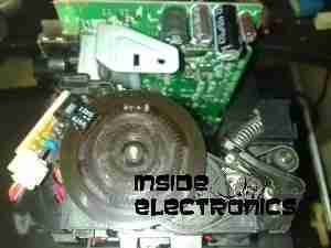
Mainshaft encoder. Main drive motor is bottom right hand side with timing belt drive.
![CPU CPU](http://www.experimental-engineering.co.uk/wp-content/uploads/2010/08/04082010052-300x225.jpg)
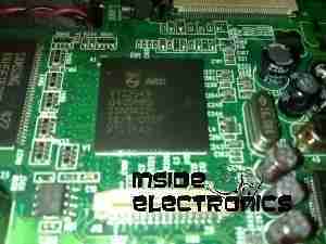
Closeup of the CPU. This is a Phillips ARM chip, unknown spec.
![Card Reader Sockets Card Reader Sockets](http://www.experimental-engineering.co.uk/wp-content/uploads/2010/08/04082010056-300x225.jpg)
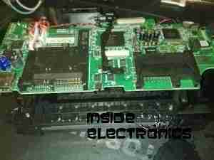
Detail of the card reader sockets, this unit takes all current types of Flash memory card.