Posted on 7 Comments

Maplin/Refrakta XR-E LED Torch

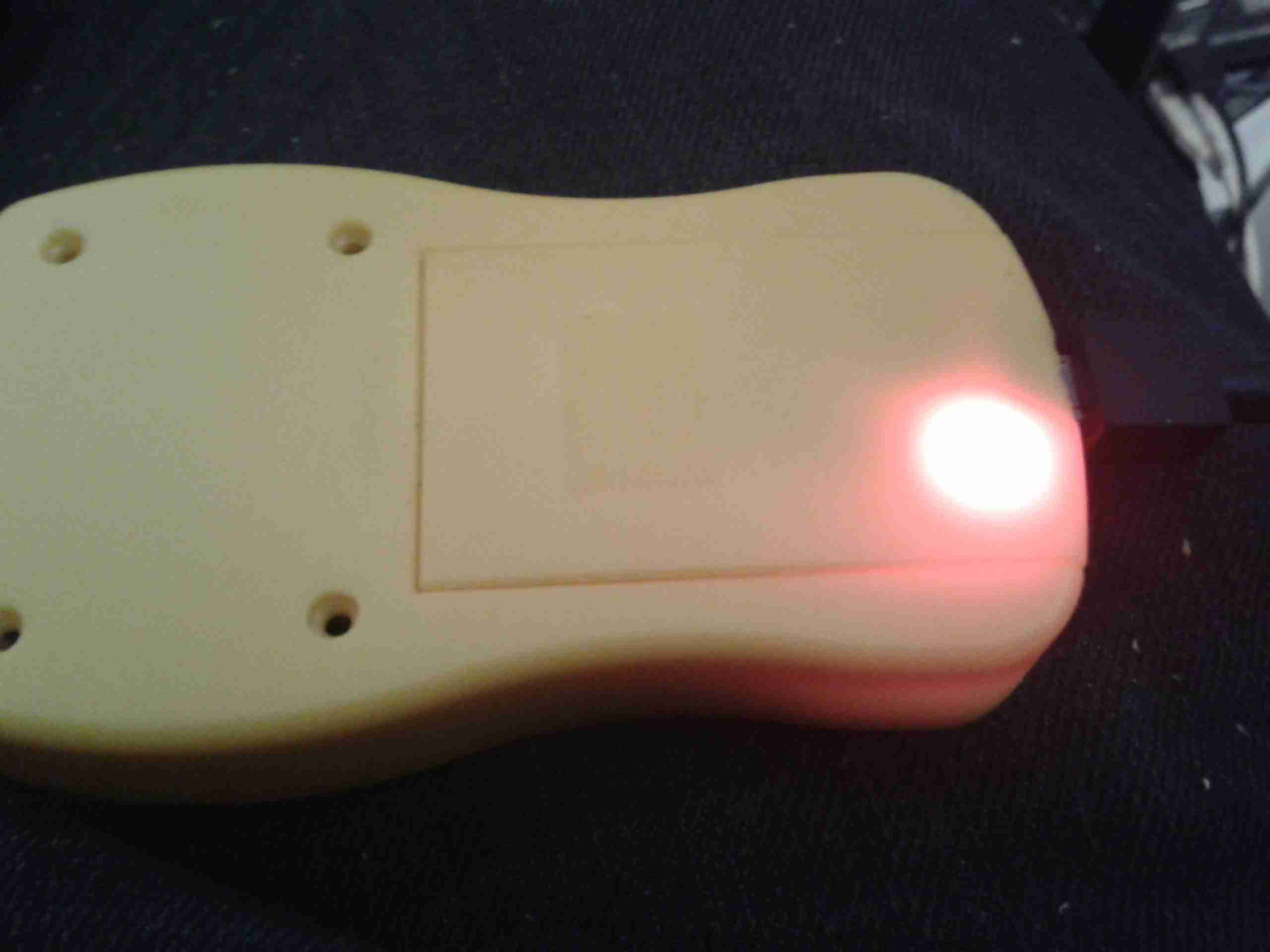
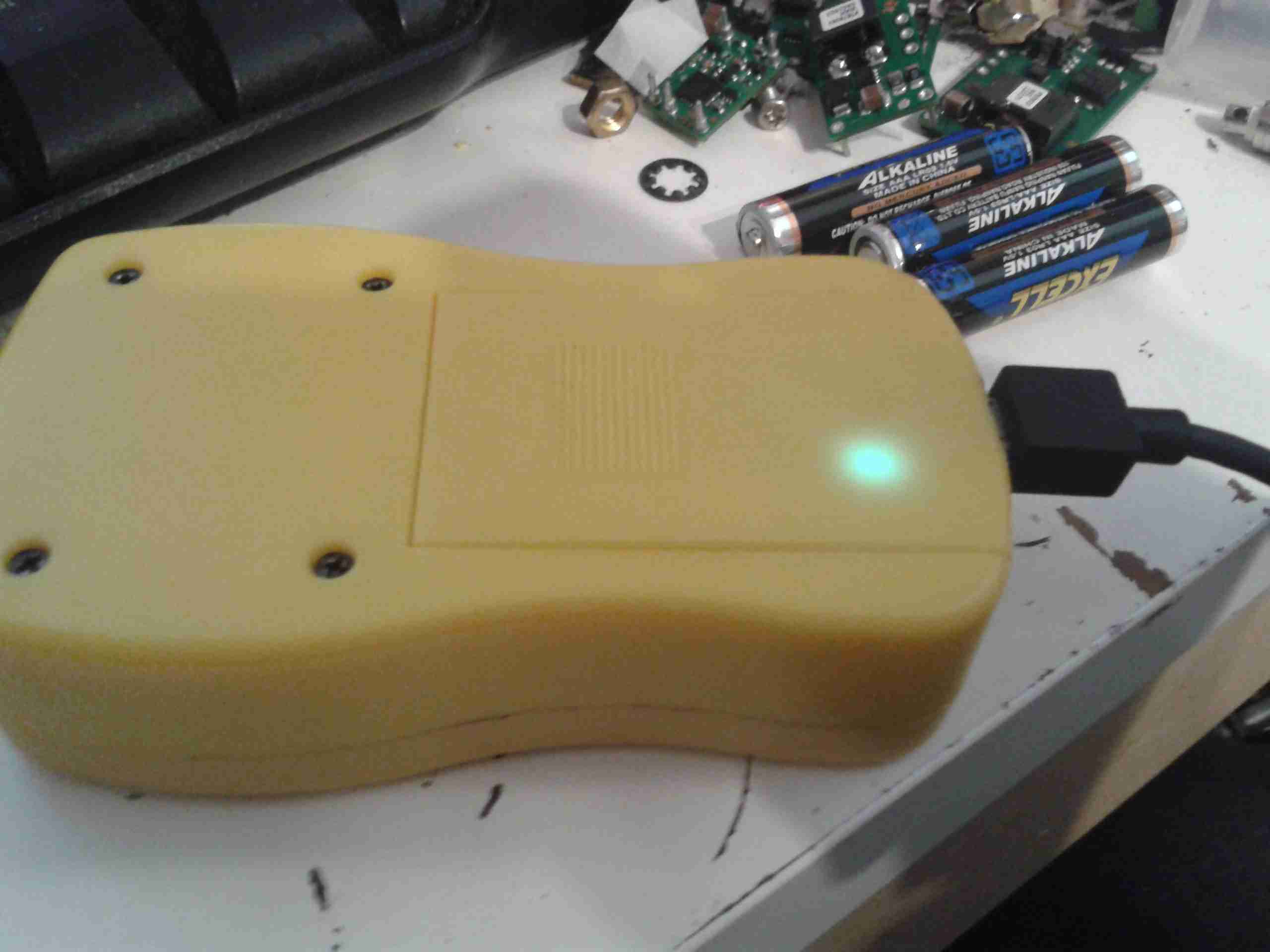
Following on from the teardown & analysis of the charger, here’s the torch itself under the spotlight.

LED Torch
LED Torch

Here’s the torch itself, it’s a sturdy device, made of aluminium. Power is provided by a single 18650 Li-Ion cell.

Charging Port
Charging Port

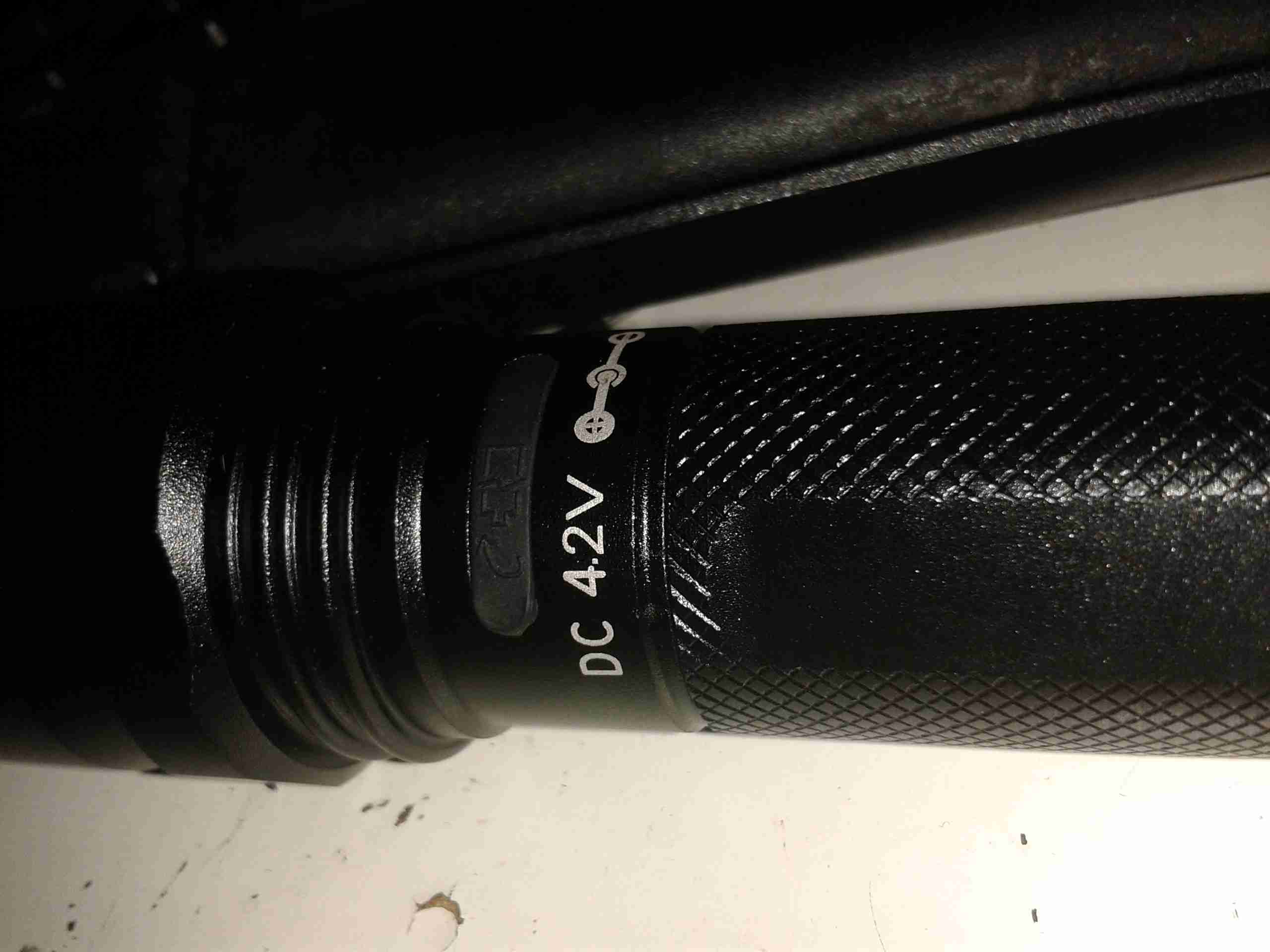
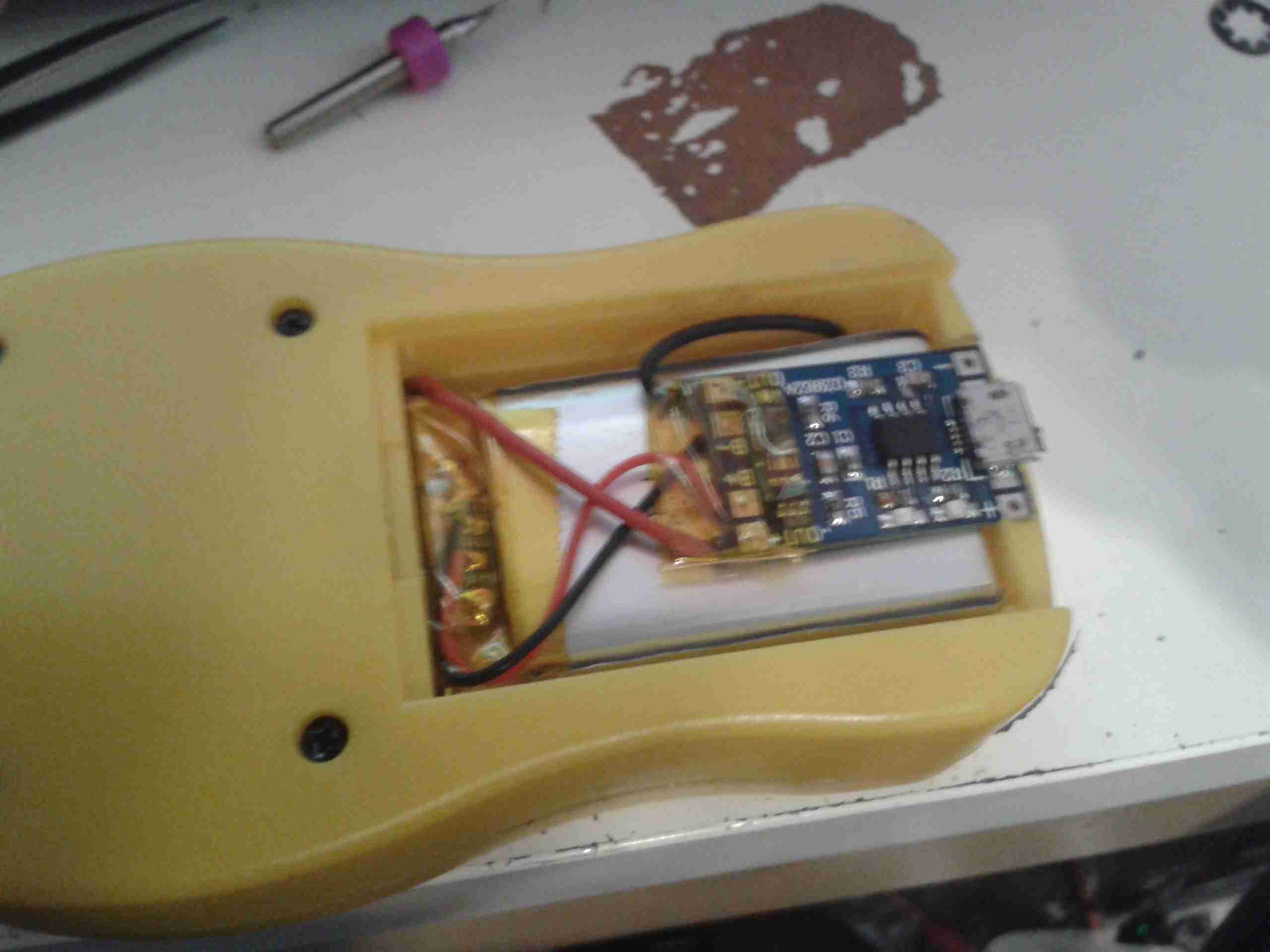
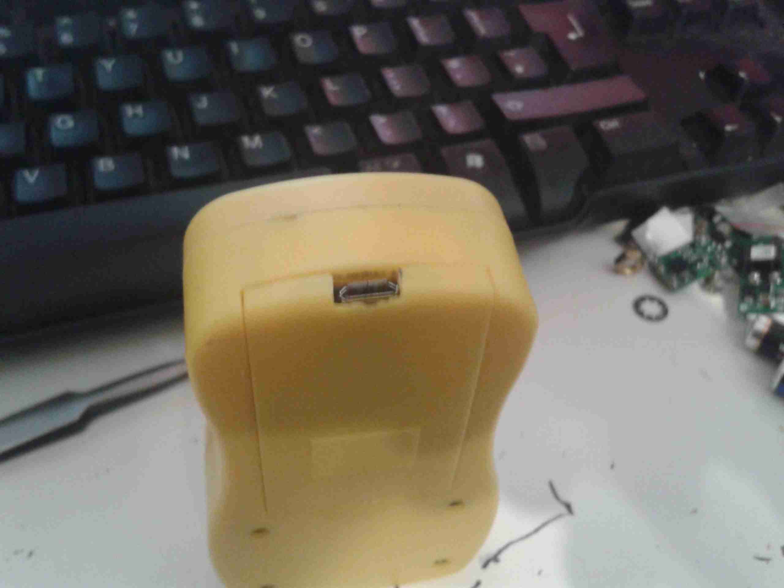
Here’s the charging port on the torch, there’s no electronics in here for controlling the charge, the socket is simply connected directly to the Li-Ion cell, and requires a proper external charger.

LED Pill
LED Pill

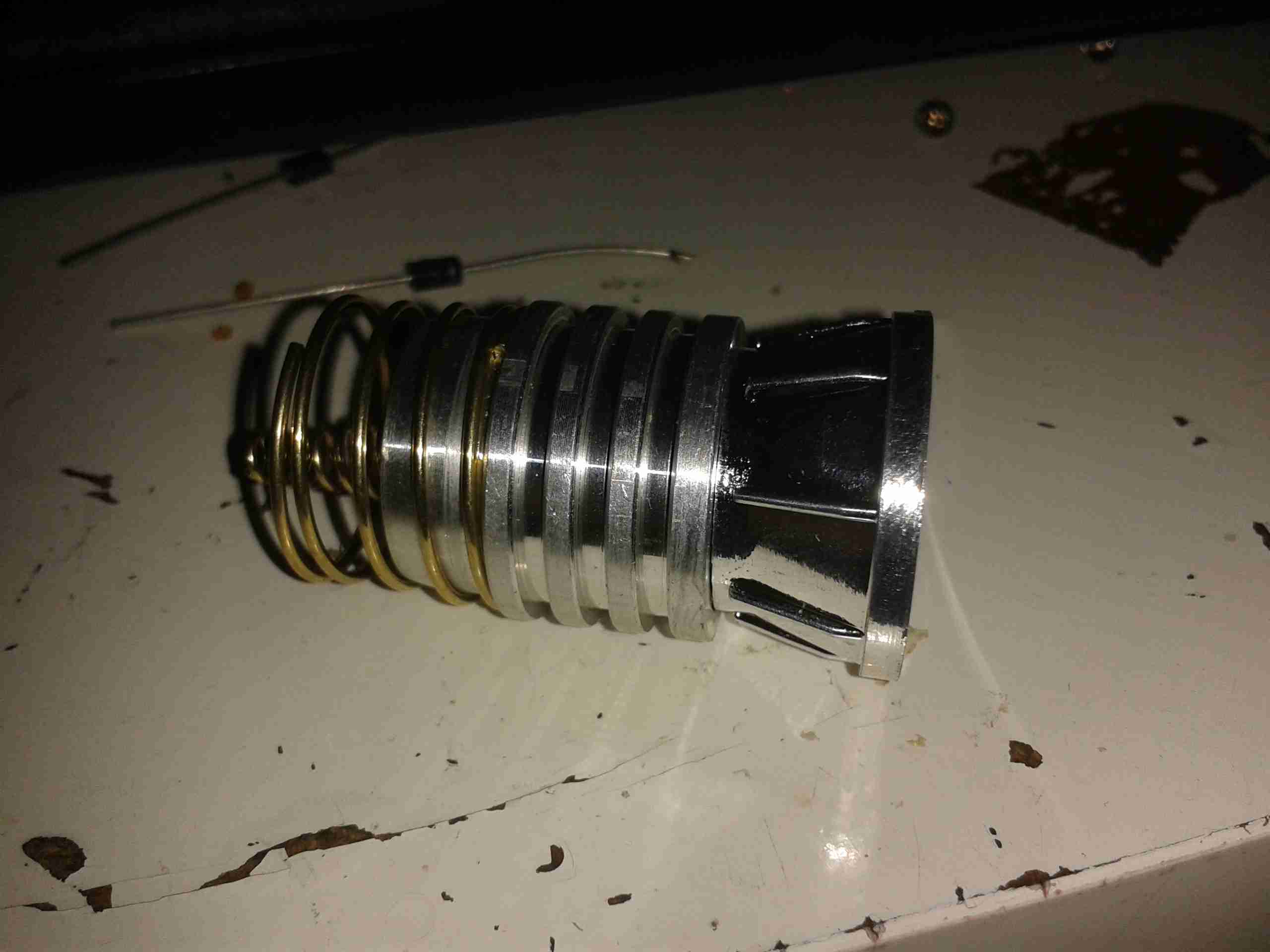
Unscrewing the lens gives access to the LED core, this also unscrews from the torch body itself, leaving the power switch & the battery in the body.

LED Module
LED Module

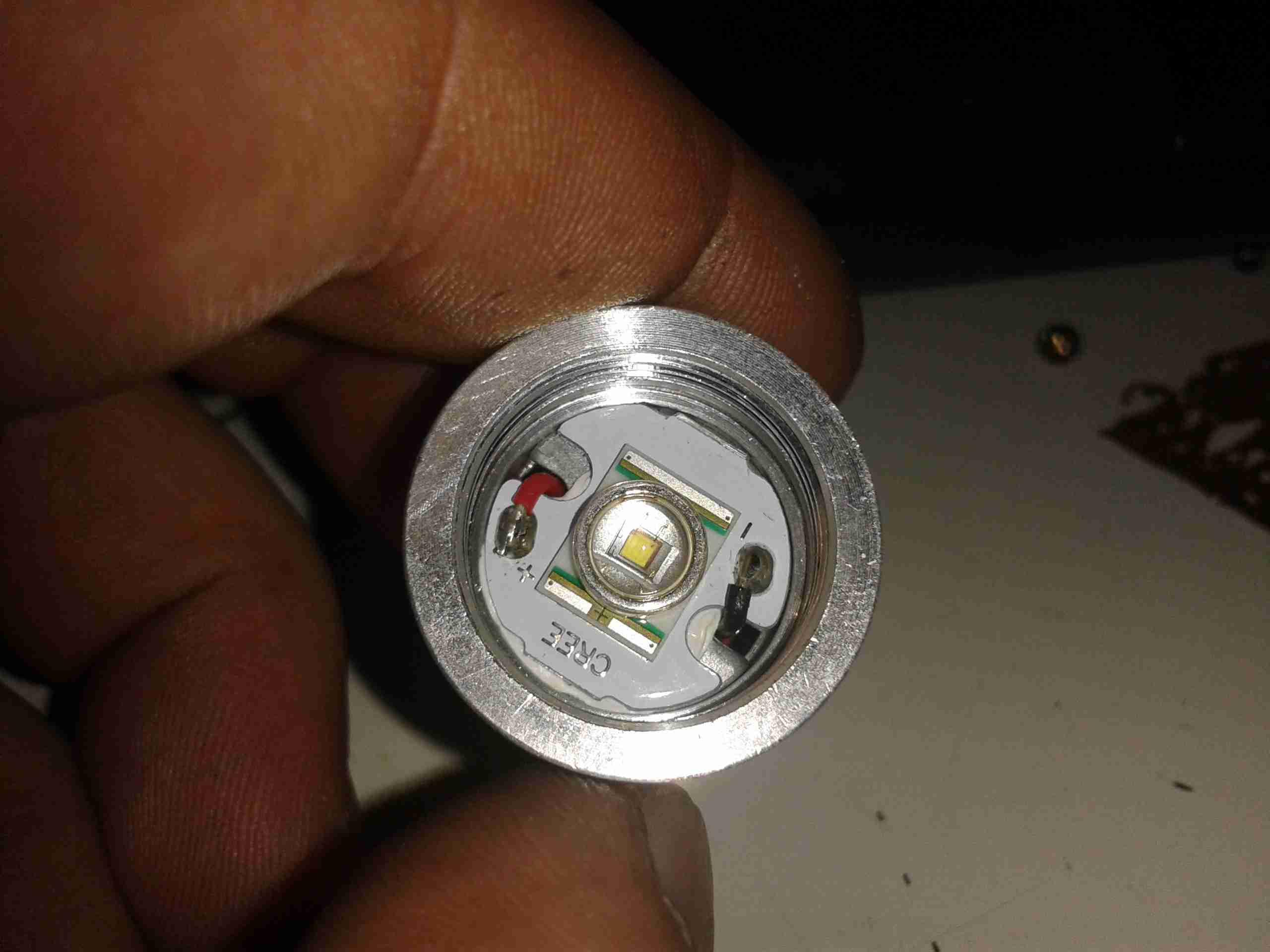
Unscrewing the aluminised plastic reflector reveals the LED itself. Being a new device, I expected an XM-L or XM-L2 Cree LED in here, but it’s actually an XR-E model, a significantly older technology, rated at max 1A of drive current.

LED Back
LED Back

Popping the control PCB out from the pill reveals a lot of empty space, but the back of the LED is completely covered by a heatsinking plate, which is conducting heat to the main body of the torch.

Control PCB
Control PCB

Not much to see on the control PCB, just a bunch of limiting resistors, and a multi-mode LED driver IC in a SOT-23 package. There’s no proper constant-current LED driver, and as the battery discharges the torch will dim, until the low voltage cutout on the cell turns things off completely.

Posted on Leave a comment

GY561 Frequency & Power Meter LiPo Conversion

From the factory, the GY561 meter uses alkaline AAA cells for power. As these are not rechargable, and I don’t carry any other devices that take such batteries, I figured I’d replace them with a single Lithium Polymer cell that I can charge via USB.

Battery Compartment
Battery Compartment

Here’s the battery compartment, with the original spring terminals removed.
I searched eBay for a suitable sized cell, and settled on a 1000mAh type, with dimensions of 47mm x 28mm x 7mm.

This size cell required a small amount of modification to the battery compartment to make it fit properly with the associated charge & protection circuitry.

Modified Compartment

Here’s the modifications made to the compartment, I’ve ground away the plastic to make the bottom flat, and the plastic tabs that retained the original spring terminals.

Modifications
Modifications

After grinding away the original battery spring holders with a dremel, the cell fits perfectly in the available space. The small PCB on the top of the cell is the USB charger & protection.

Charger
Charger

The charger is located in a slot cut in the bottom of the casing, so the USB port is accessible from outside the compartment.

Wiring
Wiring

Here’s the rest of the wiring completed, with the power wires going through holes in the bottom of the battery compartment to join onto the PCB where the original terminals were located. I have insulated the solder joints on the control PCB with some Kapton tape to prevent any shorts against the lithium cell.

Battery Cover
Battery Cover

A small cutout was also required in the battery cover to allow the USB connector to poke out. This was easy to do on the soft plastic with a Dremel tool.

Charging Port
Charging Port

With the battery cover installed, the USB port is nicely recessed into the edge.

Charging LED
Charging LED

The indicator LEDs on the charging & control board show nicely through the plastic, here’s the unit on charge. When the charge is complete, another LED lights as shown below.

Charging Complete
Charging Complete