A while back I found myself in the need of an adjustable RF attenuator capable of high-GHz operation. As luck would have it I had an old Spectrum analyser on the shelf at work, which we had retired quite some time ago.
Spectrum analysers being quite capable test instruments, I knew that the input attenuation would be done with a standalone module that we could recover for reuse without too much trouble.
The attenuator module
Here’s the module itself, with the factory drive PCB removed from the bottom, showing the solenoids that operate the RF switches. There are test wires attached to them here to work out which solenoid switches which attenuation stage. In the case of this module, there are switches for the following:
Input select switch
AC/DC coupling
-5dB
-10dB
-20dB
-40dB
For me this means I have up to -75dB attenuation in 5dB steps, with optional switchable A-B input & either AC or DC coupling.
Drive is easy, requiring a pulse on the solenoid coil to switch over, the polarity depending on which way the switch is going.
Building a Control Board
Now I’ve identified that the module was reusable, it was time to spin up a board to integrate all the features we needed:
Onboard battery power
Pushbutton operation
Indication of current attenuation level
The partially populated board is shown at right, with an Arduino microcontroller for main control, 18650 battery socket on the right, and control buttons in the centre. The OLED display module for showing the current attenuation level & battery voltage level is missing at the moment, but it’s clear where this goes.
As there weren’t enough GPIO pins for everything on the Arduino, a Microchip MC23017 16-Bit I/O expander, which is controlled via an I²C bus. This is convenient since I’m already using I²C for the onboard display.
Driving the Solenoids
A closer view of the board shows the trip of dual H-Bridge drivers on the board, which will soon be hidden underneath the attenuator block. These are LB1836M parts from ON Semiconductor. Each chip drives a pair of solenoids.
Power Supplies
The bottom of the board has all the power control circuitry, which are modularised for ease of production. There’s a Lithium charge & protection module for the 18650 onboard cell, along with a boost converter to give the ~9v rail required to operate the attenuator solenoids. While they would switch at 5v, the results were not reliable.
Finishing off
A bit more time later, some suitable firmware has been written for the Arduino, and the attenuator block is fitted onto the PCB. The onboard OLED nicely shows the current attenuation level, battery level & which input is selected.
While sourcing the main propulsion hydraulic system for nb Tanya Louise in the summer, we thought that it would be convenient to have an on board generator that didn’t require dragging off the boat & highly explosive petrol to operate.
As the hydraulics were already being fitted, we decided to add a hydraulically driven generator to solve this issue.
And this is where the problems began…
We were referred to Mike Webb of hydraulicgenerators.co.uk to supply the equipment required for this part of the project, this was to include the alternator itself, hydraulic motor to drive the alternator, the required adaptor plates to mate the motor to the generator head & a control valve block to regulate the oil flow & pressure to the motor.
After a phone call to Mike on 16-07-2013 to discuss our requirements, we settled on a system. I received the following E-Mail the next day from Mike:
Good morning, reference our conversation, Martin from BSP has given me details as to what he will be supplying, on that basis and in light of the special price I have offered, this is what I propose to supply,
1 off New 8kVa – 7kW Hydraulic driven generator 220v single phase 50hz c/w flow control valve, pressure relief valve and on/off solenoid valve, Martin did say that the engine idle is between 1000 and 1200 rpm and max speed is 3600 rpm, valves will be rated accordingly. I have the alternator and parts available now, in order for me to be able to offer this at a significantly discounted price of £ 1.200.00 nett, I will need to utilise the components I have in stock now, so I will need payment asap, delivery will be approx. 7 days, primarily due to the fact that the coupling is fabricated to suit, I can either deliver the unit to you when ready or BSP or hold onto it until everything else is in place. The alternator is a Meccalte S20W that I bought for another customer a few weeks ago, but he cancelled and I don’t have, at this time, anyone else interested in it, so either I do a deal with you at the above price or wait until someone else comes along and wants the unit.
With regards to installation, let me know if you need any help, but it would be best to install when the engine is being installed and the rest of the system hosed up, I assume BSP will be sorting this, in which case I’ll liase with Martin.
I trust that this meets with your approval and look forward to hearing from you.
At this point an order was placed with Mike, & the money transferred so he could begin building the unit for us. As can be seen from the E-Mail, a lead time of 7 days was stated.
After a few phone calls over the following month, firstly being told that the custom parts to mate the generator to the motor had not come back from the engineers, I sent another E-Mail to Mike on 10-09-2013, and got no reply.
Following another phone call, I was told that the generator had been shipped, however Mike would not give me any tracking details for the shipment, and would not initially tell me who it was shipped with.
Again the generator didn’t turn up.
More phone calls ensued & I was told at this point that the shipping company had been confused by the address given, shipped back to Mike. At this point I was informed that the shipping company had actually LOST it. Several more phone calls later I was promised that a replacement generator would now ship no later than 08-10-2013. A follow up E-Mail two days later also generated no reply.
At this point I was beginning to wonder if I would ever see the goods we had paid for, but finally a shipment arrived from Mike
~15-10-2013, over TWO MONTHSafter our promised delivery date. However, even having been delivered, all was not well with the goods.
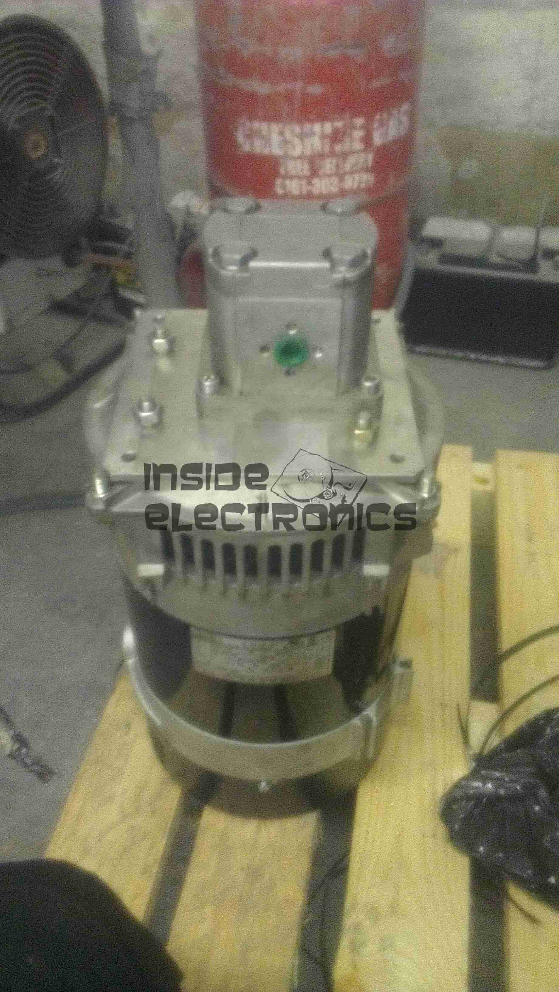
Generator Pallet
Above is the generator supplied. No mounting bracket, no integrated valve block, in short, nothing like what was described in Mike’s documentation & website. The original documentation is available here for reference: [download id=”5564″]
As can be seen, there is an open port on the side of the valve block. This is where the ON/OFF control solenoid valve is supposed to be located.
After several more unanswered E-Mails & phone calls, I had to get somewhat more forceful in my messages, as now Mike had begun outright lying about what was specified in the original order. In which that there was no solenoid valve required. So the following E-Mail was sent 21-10-2013:
Mike,
Having had a conversation with Martin, about him attempting to contact you regarding what you have supplied to us, I need this resolving ASAP now, as I am being held up by the fact that there is an open port on your valve block where the solenoid control valve is supposed to be located.
As it stands the valve block & therefore the generator you have supplied to us is useless for it’s intended purpose & I will be seeking legal advice on this matter if a resolution cannot be made this week, considering you have not replied to any E-Mail I have sent since the unit’s massively delayed arrived.
In your original correspondence it is certainly indicated that this valve was to be fitted, which was also Martin’s instruction to you.
I await your expedient response.
This threat of legal action actually spurred a response from Mike, who finally replied with the following on 25-10-2013:
Ben,
Sorry about all this, I have been away and down with a bug for the last week, I will sort this today and will have the required parts shipped to you on Monday for Tuesday delivery.
Regards
Mike
Another promise of a delivery date, so I waited a little longer, until the Friday of that week. Still no delivery. No surprise there then.
(I didn’t believe the story about illness either).
At this point I again attempted contact, but got nowhere, even with legal threats. So I’ve given up completely on this & been forced to source the parts elsewhere at extra cost.
This company is not the one to go to if you require a hydraulic generator unit for any application, as you’d be lucky to get any part of what you order on time, if at all.
Operations are run by an all out liar who seems to be happy to accept money but not ship the goods that had been paid for.
Mike having explained to me that the shipping company had lost a generator, and he would have to build me another one to replace it also does not make sense, as in the initial phone call & mail he stated that the Meccalte generator that we eventually received was a single unit that was specially ordered for another client, and the factory build date on the unit certainly gave away the fact that the generator head had been sat around for some considerable time before I came along & made a purchase.
Hopefully this post will get a high Google ranking, to ensure that anyone else who happens to be looking for a similar piece of equipment does not have the misfortune to trust this man.
We were referred to him on good faith & unfortunately in this case it did not go well.
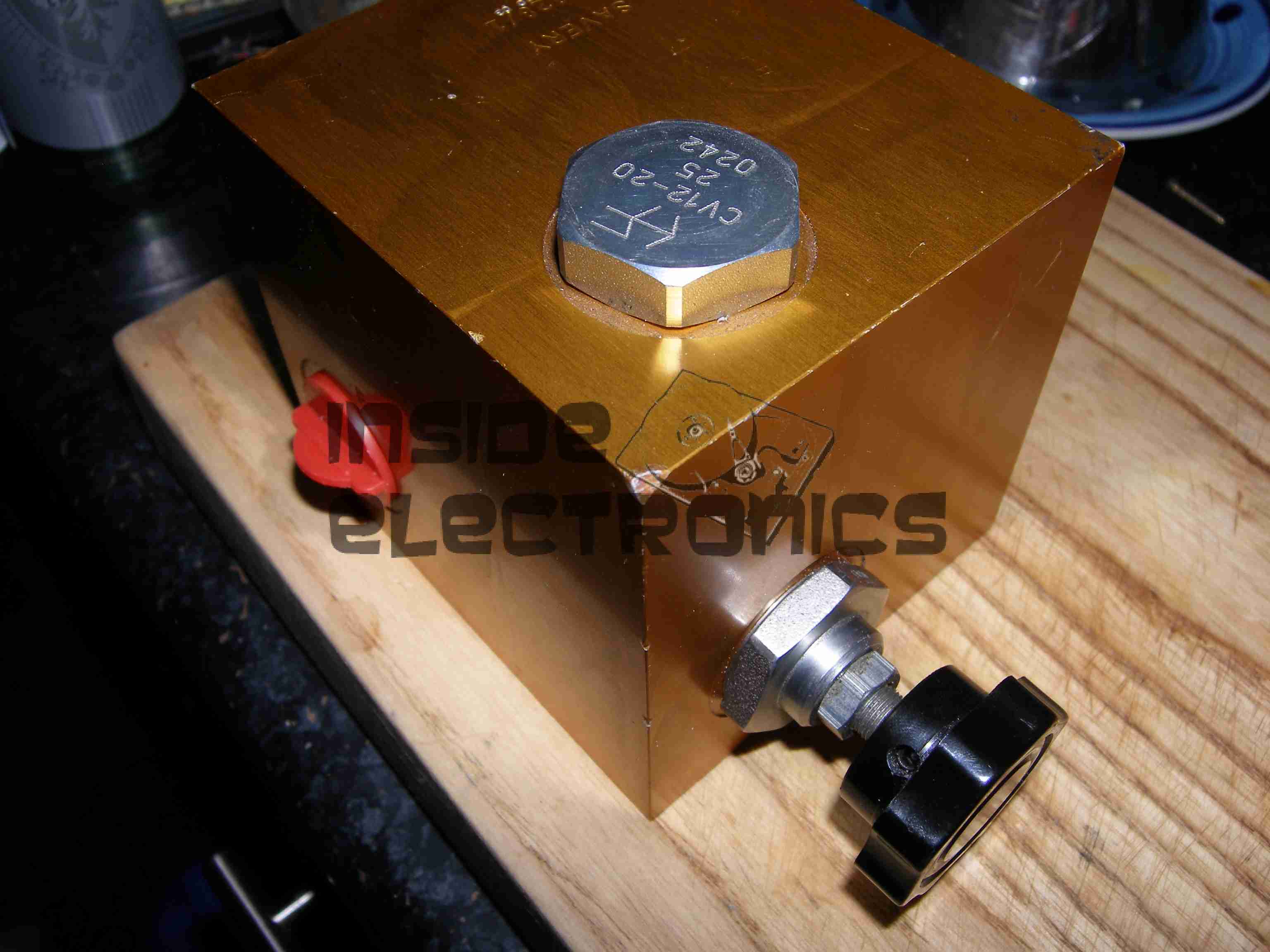
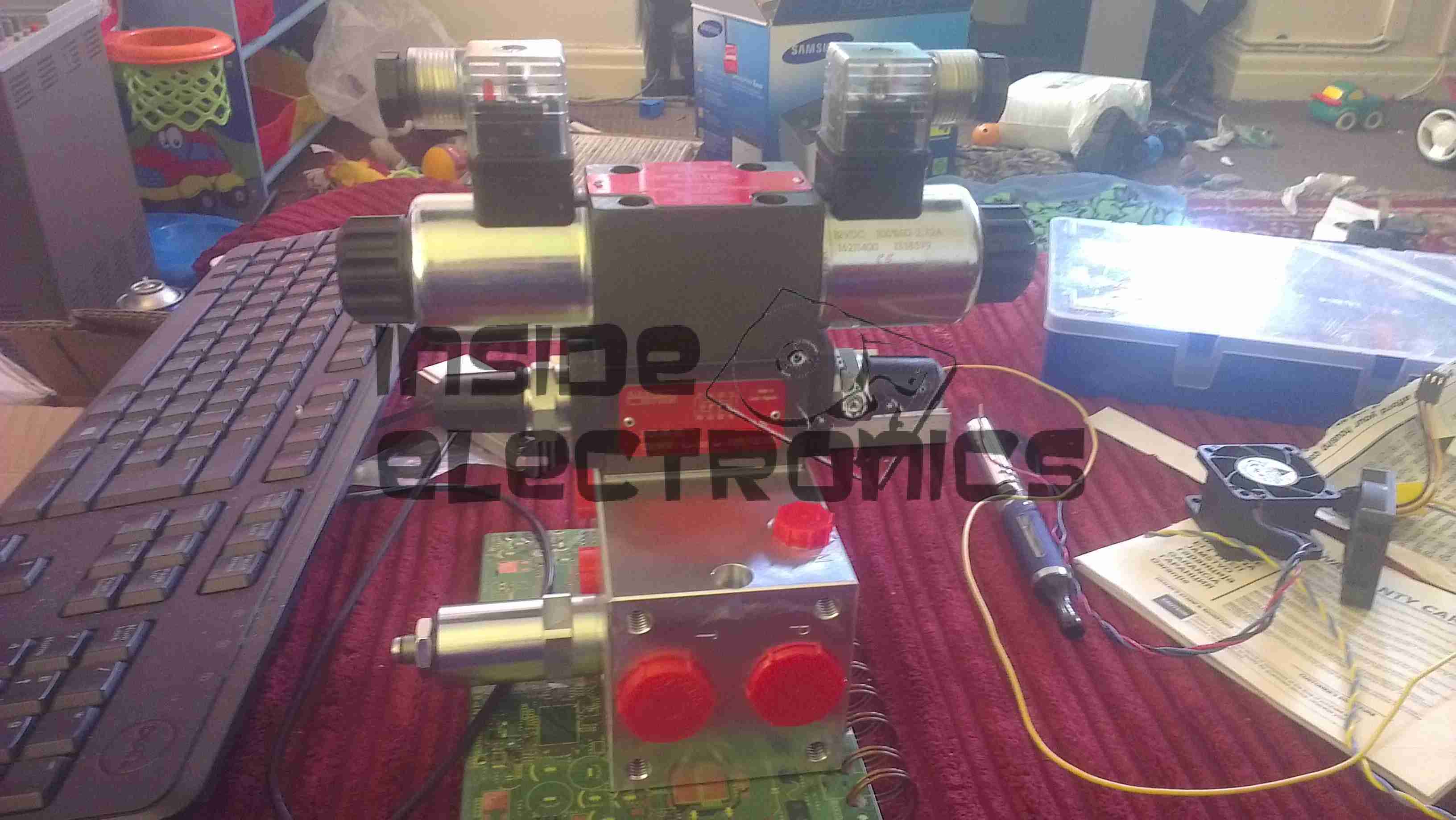
Finally, after months of messing about with the original seller of the generator unit, (Mike Webb from hydraulicgenerators.co.uk, more to come about the nightmare I had dealing with this man), we have had to purchase a new hydraulic control valve for the genset, as the original unit supplied was missing parts.
Thanks to Martin Bullock from BSP Hydraulics for supplying this at short notice!
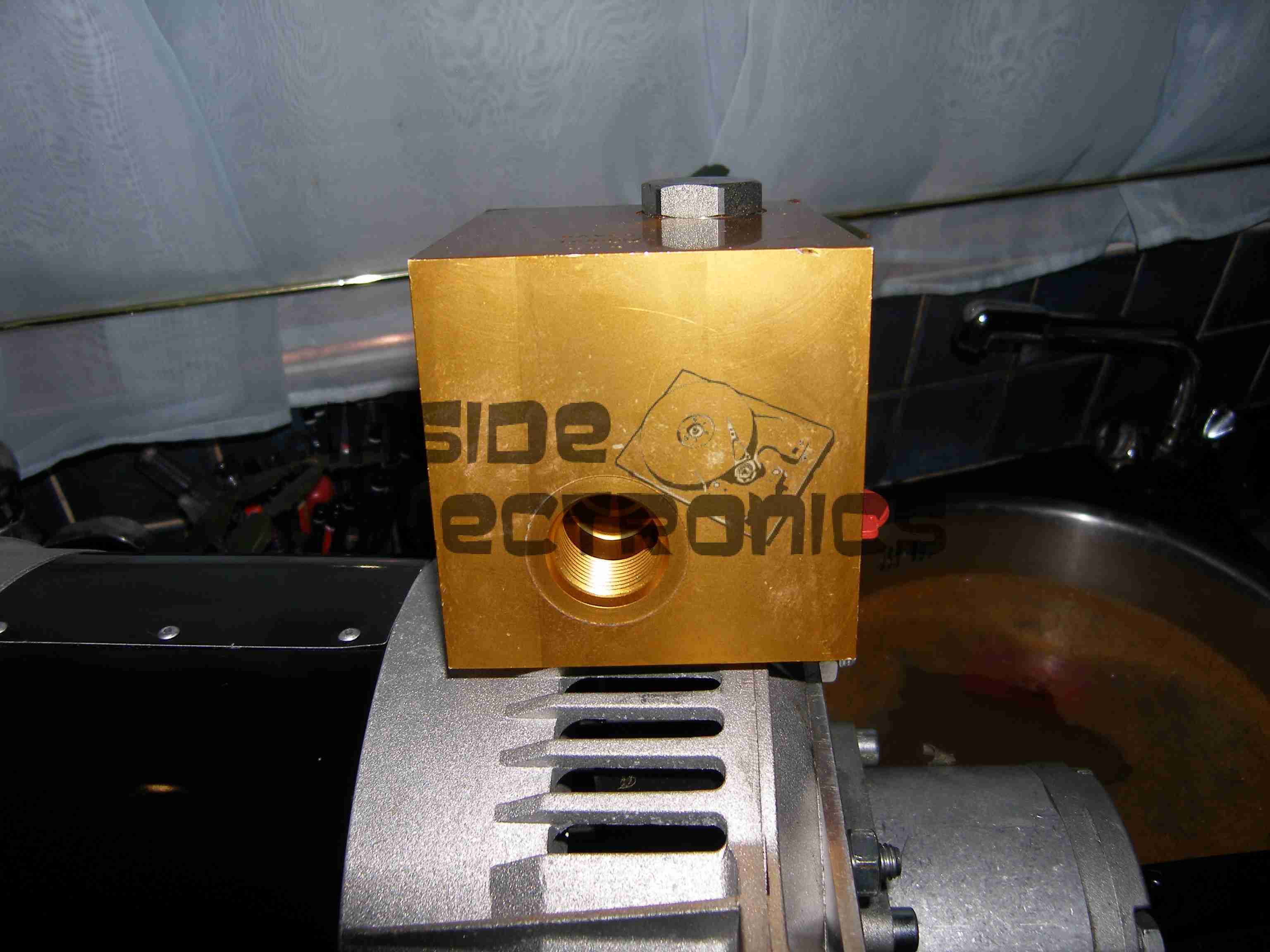
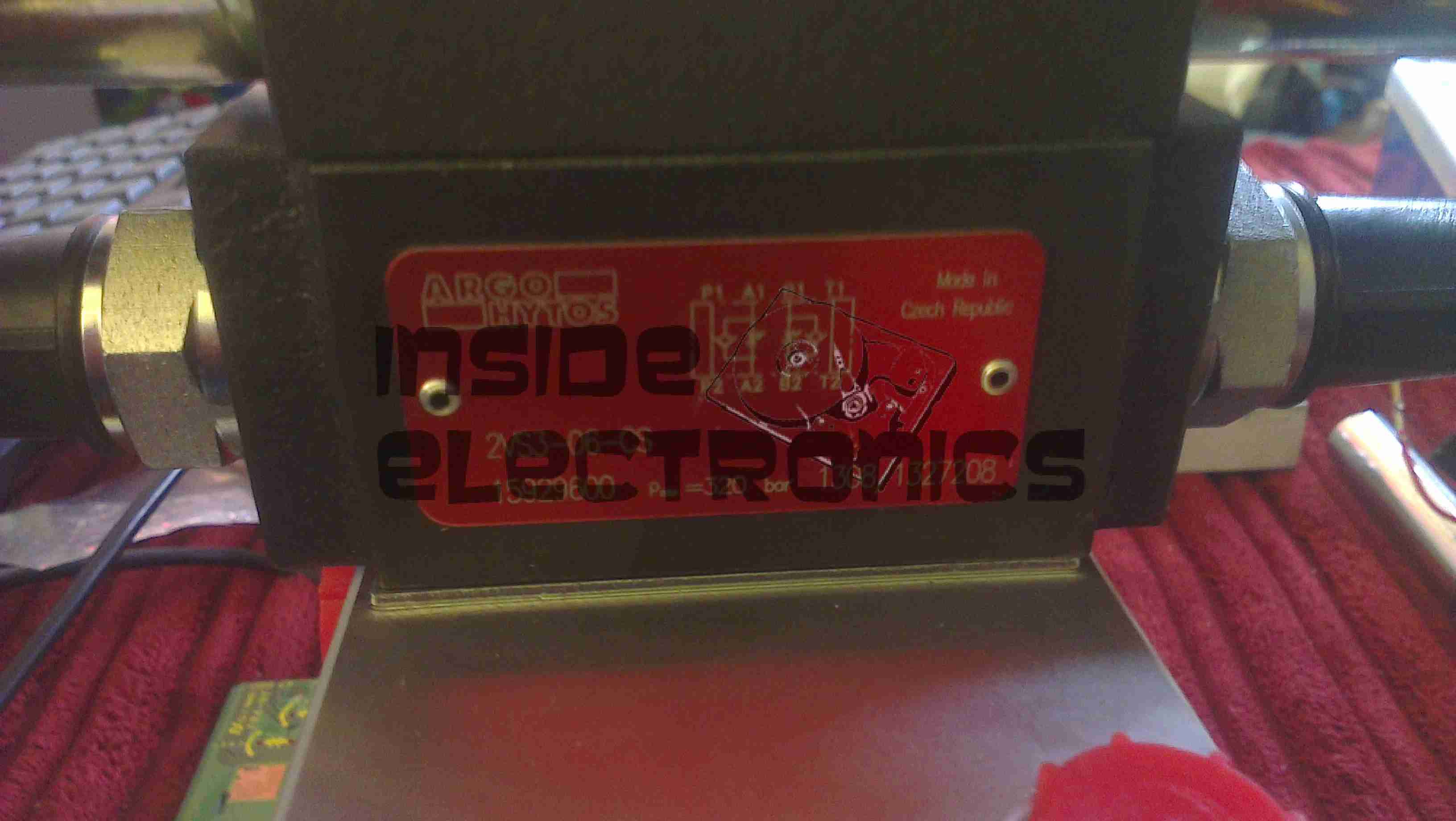
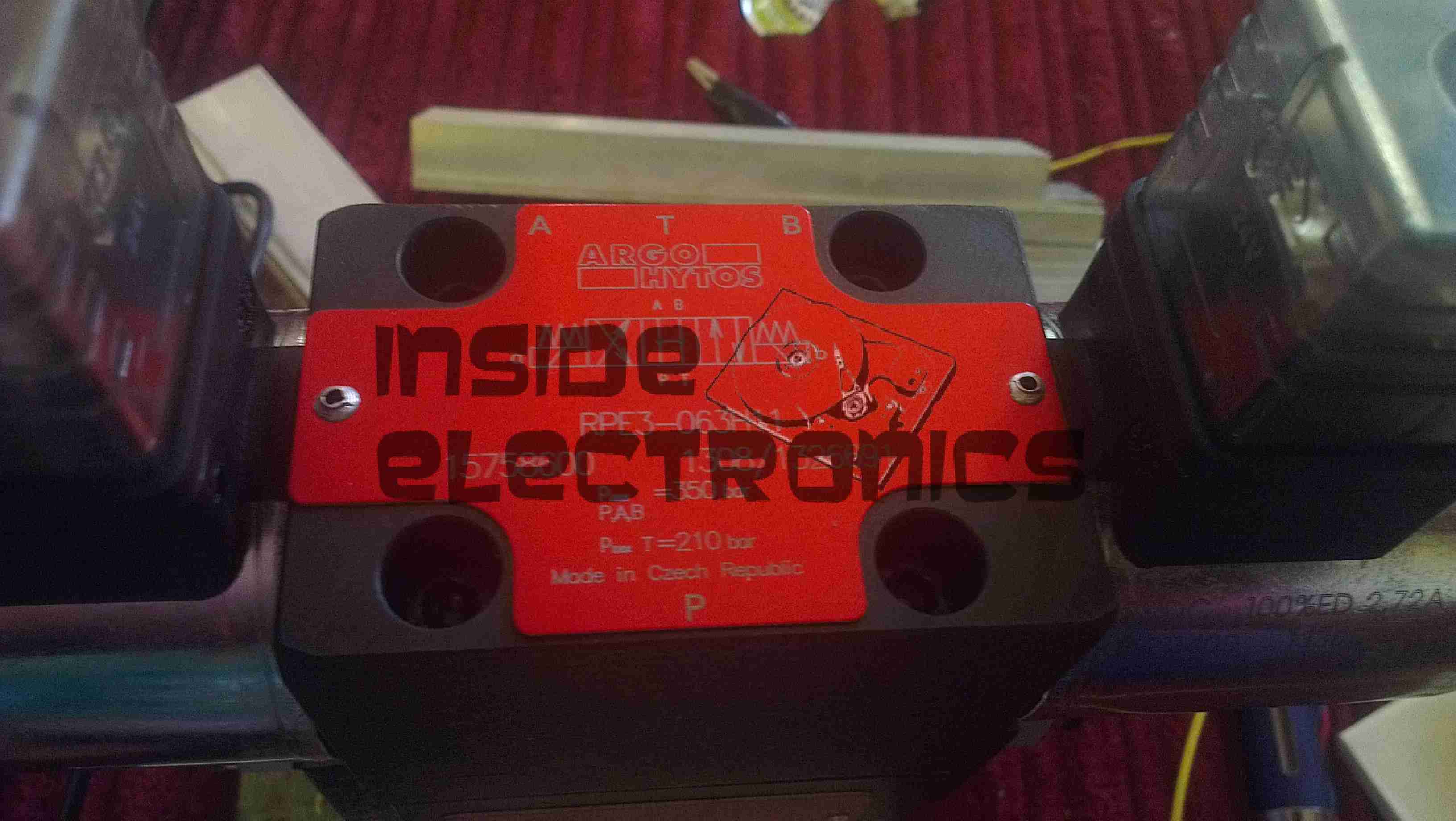
Flow Control ModuleSolenoid Spool ValveControl Valve Block
This unit contains a pressure relief valve, to set system operating pressure, a throttle/flow control valve to set generator motor speed & a solenoid controlled spool valve to control general oil flow to the generator. This last section effectively operates as an ON/OFF control.
System pressure will be ~175 Bar at 21 litres/minute.
More to come soon with the final assembly, hosing up & system commissioning.
This is a late 90’s business timeclock, used for maintaining records of staff working times, by printing the time when used on a sheet of card.
Front Internal
Here is the top cover removed, which is normally locked in place to stop tampering. The unit is programmed with the 3 buttons & the row of DIP switches along the top edge.
Instructions
Closeup of the settings panel, with all the various DIP switch options.
CPU & Display
Cover plate removed from the top, showing the LCD & CPU board, the backup battery normally fits behind this. The CPU is a 4-bit microcontroller from NEC, with built in LCD driver.
PSU & Drivers
Power Supply & prinhead drivers. This board is fitted with several NPN Darlington transistor arrays for driving the dox matrix printhead.
Printhead
Printhead assembly itself. The print ribbon fits over the top of the head & over the pins at the bottom. The drive hammers & solenoids are housed in the circular top of the unit.
Printhead Bottom
Bottom of the print head showing the row of impact pins used to create the printout.
Bottom of the solenoid assembly with the ribbon cable for power. There are 9 solenoids, to operate the 9 pins in the head.
Return Spring
Top layer of the printhead assembly, showing the leaf spring used to hold the hammers in the correct positions.
Hammers
Hammer assembly. The fingers on the ends of the arms push on the pins to strike through the ribbon onto the card.
Solenoids
The ring of solenoids at the centre of the assembly. These are driven with 3A darlington power arrays on the PSU board.
Gearbox Internals
There is only a single drive motor in the entire unit, that both clamps the card for printing & moves the printhead laterally across the card. Through a rack & pinion this also advances the ribbon with each print.
I bought one of these cheap HID kits from eBay to build a high-brightness work light that I could run from my central 12v supply.
At £14.99 I certainly wasn’t expecting anything more than the usual cheap Chinese construction. And that’s definitely what I got 😀
Potted PCB
The casing is screwed together with the cheapest of screws, with heads that are deformed enough to present a problem with removal.
As can be seen here, the inside of the unit is potted in rubber compound, mostly to provide moisture resistance, as these are for automotive use.
The ballast generates a 23kV pulse to strike the arc in the bulb, then supplies a steady 85v AC at 3A, 400Hz to maintain the discharge.
This module could quite easily be depotted as the silicone material used is fairly soft & can be removed with a pointed tool.
Hi-Lo Bulb Assembly
Here is the bulb removed from it’s mount. Under the bulb itself is a solenoid, which tilts the bulb by a few degrees, presumably to provide dim/dip operation for a headlight. This functionality is superfluous to my requirements.
An old IDE interface Zip drive. This fits in a standard 3.5″ bay.
Cover Removed
Top cover removed from the drive, IDE & power interfaces at the top, in centre is the eject solenoid assembly & the head assembly. Bottom is the spindle drive motor.
Head Assembly
Head assembly with the top magnet removed. Voice coil is on the left, with the head preamp IC next to it. Head chips are on the end of the arm inside the parking sleeve on the right. Blue lever is the head lock.
Controller
Controller PCB removed from the casing.
Spindle Motor
Spindle motor. This is a 3-phase DC brushless type motor. Magnetic ring on the top engages with the hub of the Zip disk when insterted into the drive.
Magnets
Magnets that interact with the voice coil on the head assembly.
Head Armature
Head armature assembly removed from the drive. The arm is supported by a pair of linear bearings & a stainless steel rod.
Tip Jar
If you’ve found my content useful, please consider leaving a donation by clicking the Tip Jar below!
All collected funds go towards new content & the costs of keeping the server online.