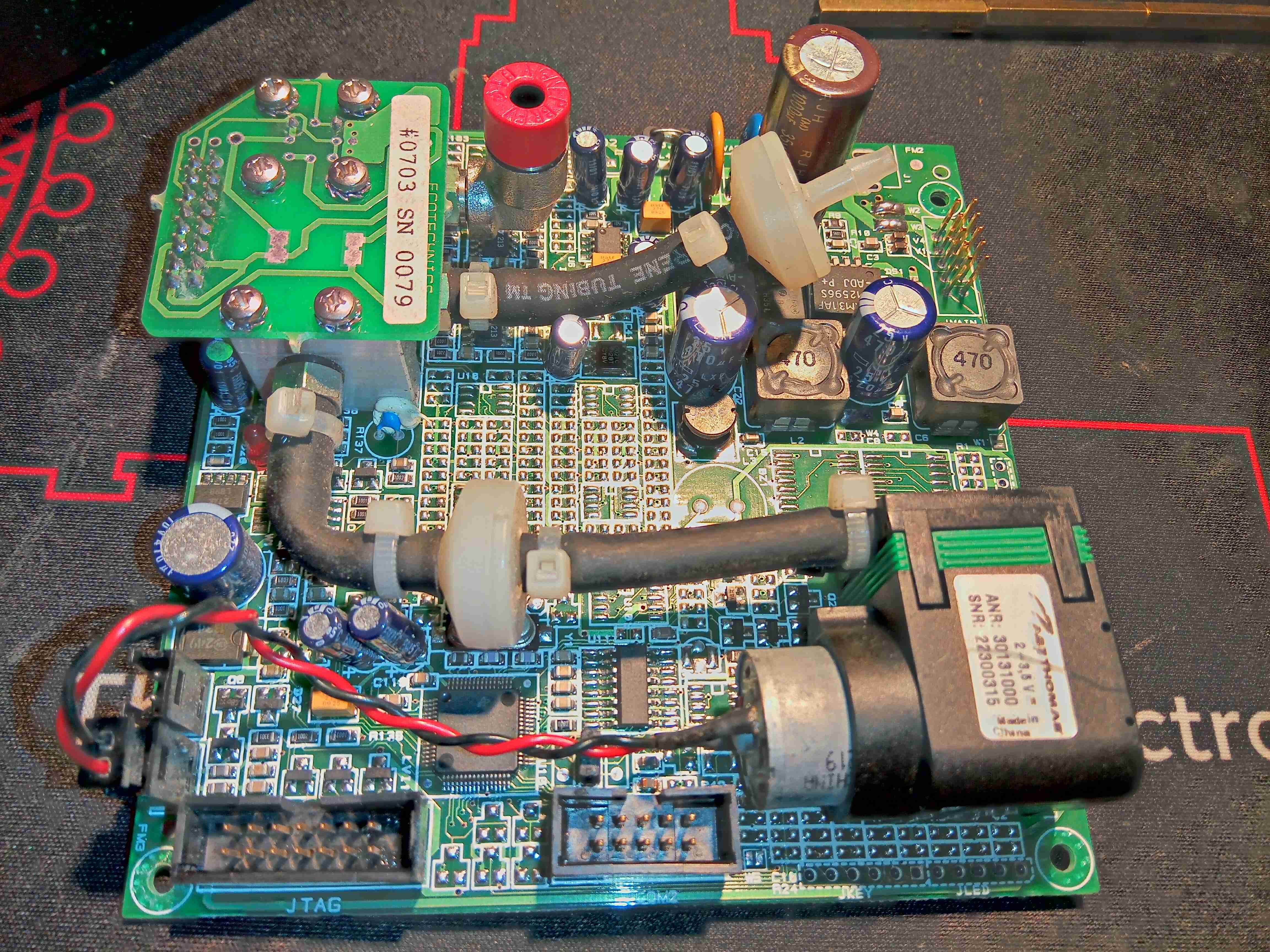
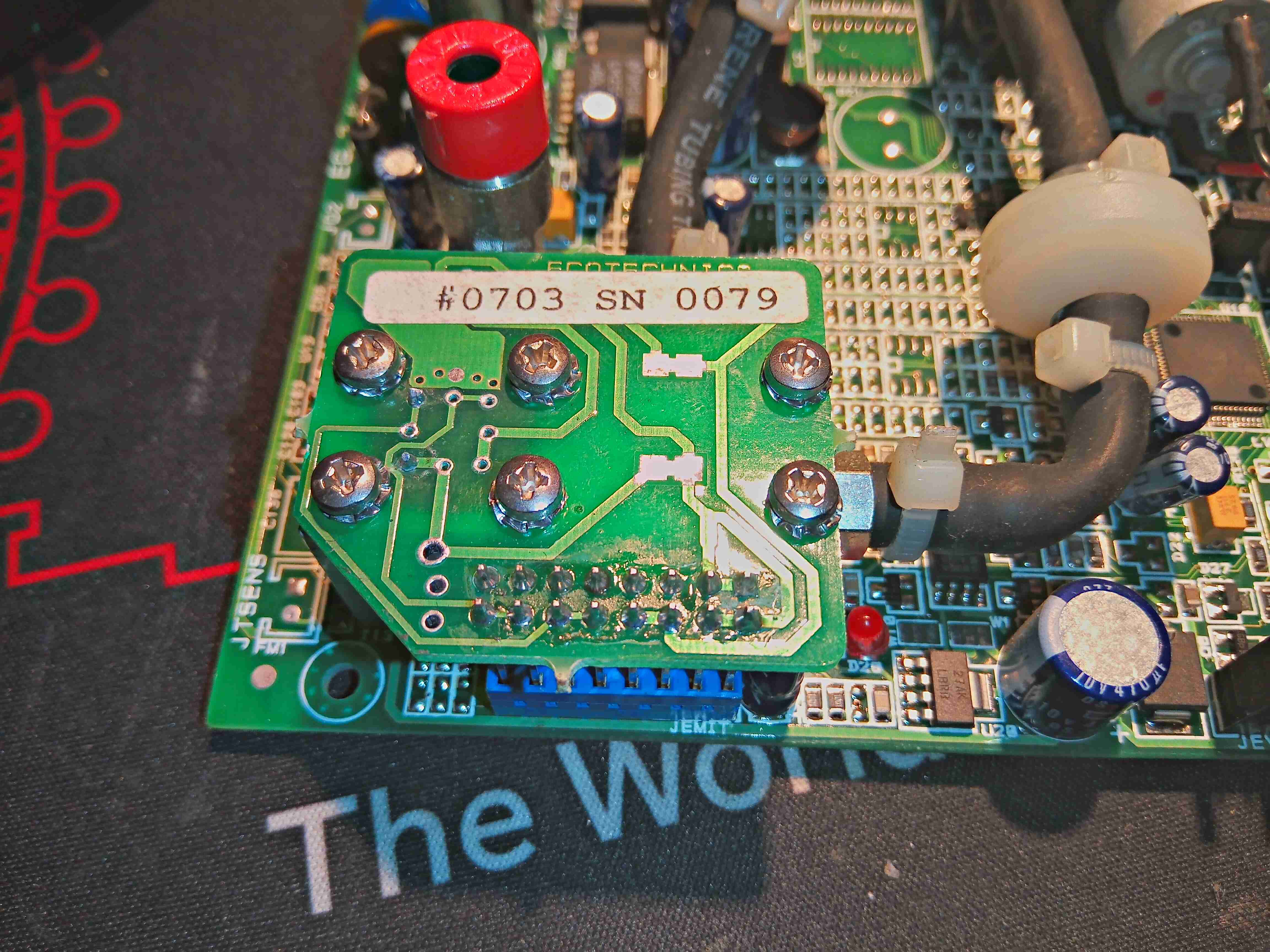
This unit recently appeared on eBay, as a spare part from a refrigerant charging machine, and I figured it would make a good explorational post. This unit analyses the purity of R-134a refrigerant gas, using an Infrared sensor cell, and communicates over RS-232.
The sensor cell itself is at the top right of the board, we’ll get to that later on. There’s a small diaphragm pump at the lower right, for purging the cell with air. The port with the red cap is the outlet, and the remaining open hose barb is the input of gas to be tested. This would connect to a flow regulator & solenoid valve that the board controls.
It’s pretty clear that this board has multiple applications from all the unpopulated components. There’s space for a keypad, indicator LEDs & an LCD on board, so maybe this can also be fitted to a handheld analyser?
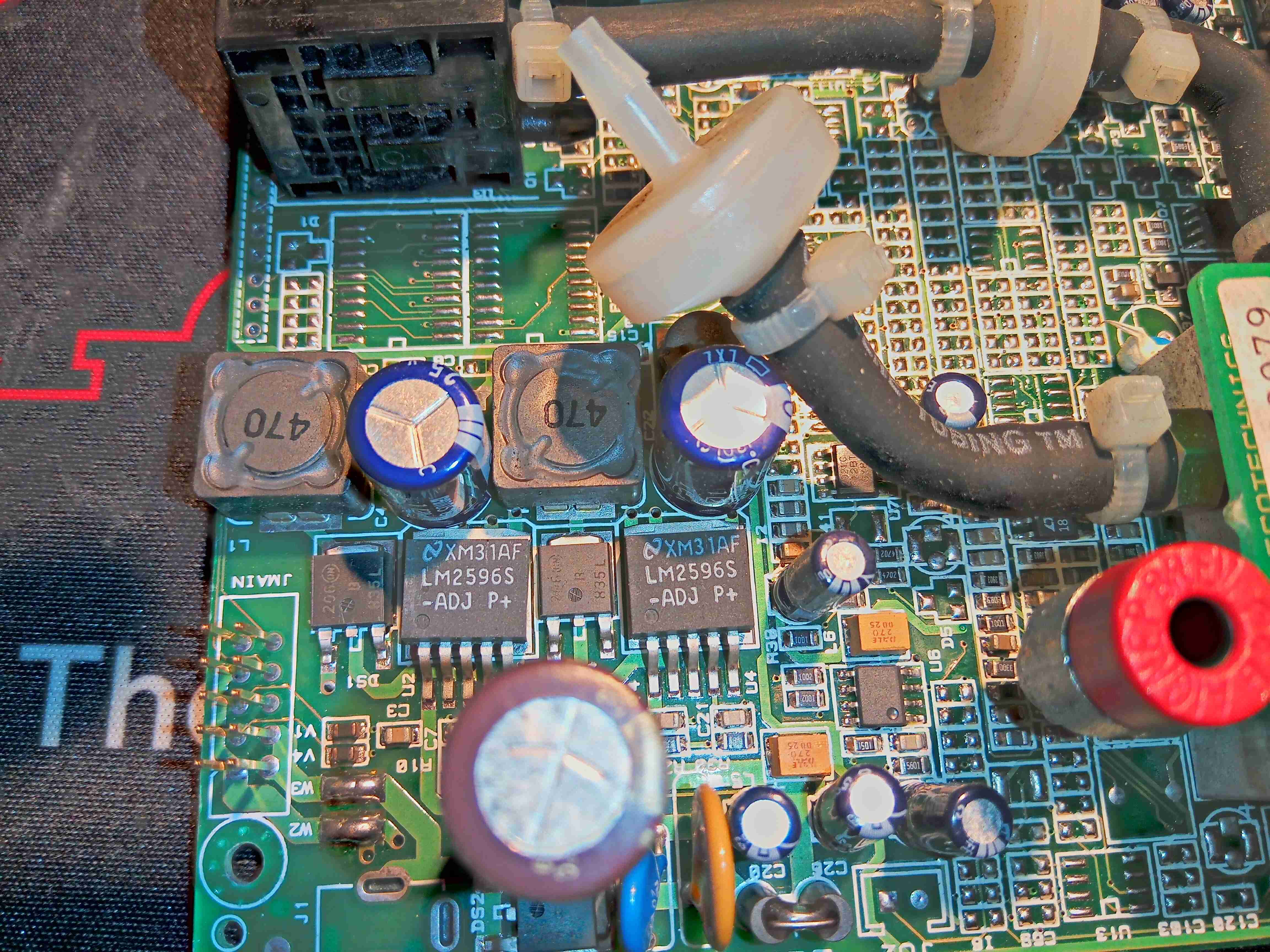
From looking at the input circuitry, I can surmise that the input voltage is somewhere between 12-24v DC, as there is a 35v input electrolytic filter capacitor. There’s a couple of switching regulators which generate 5v & 3.3v rails for the board, with some input fusing.
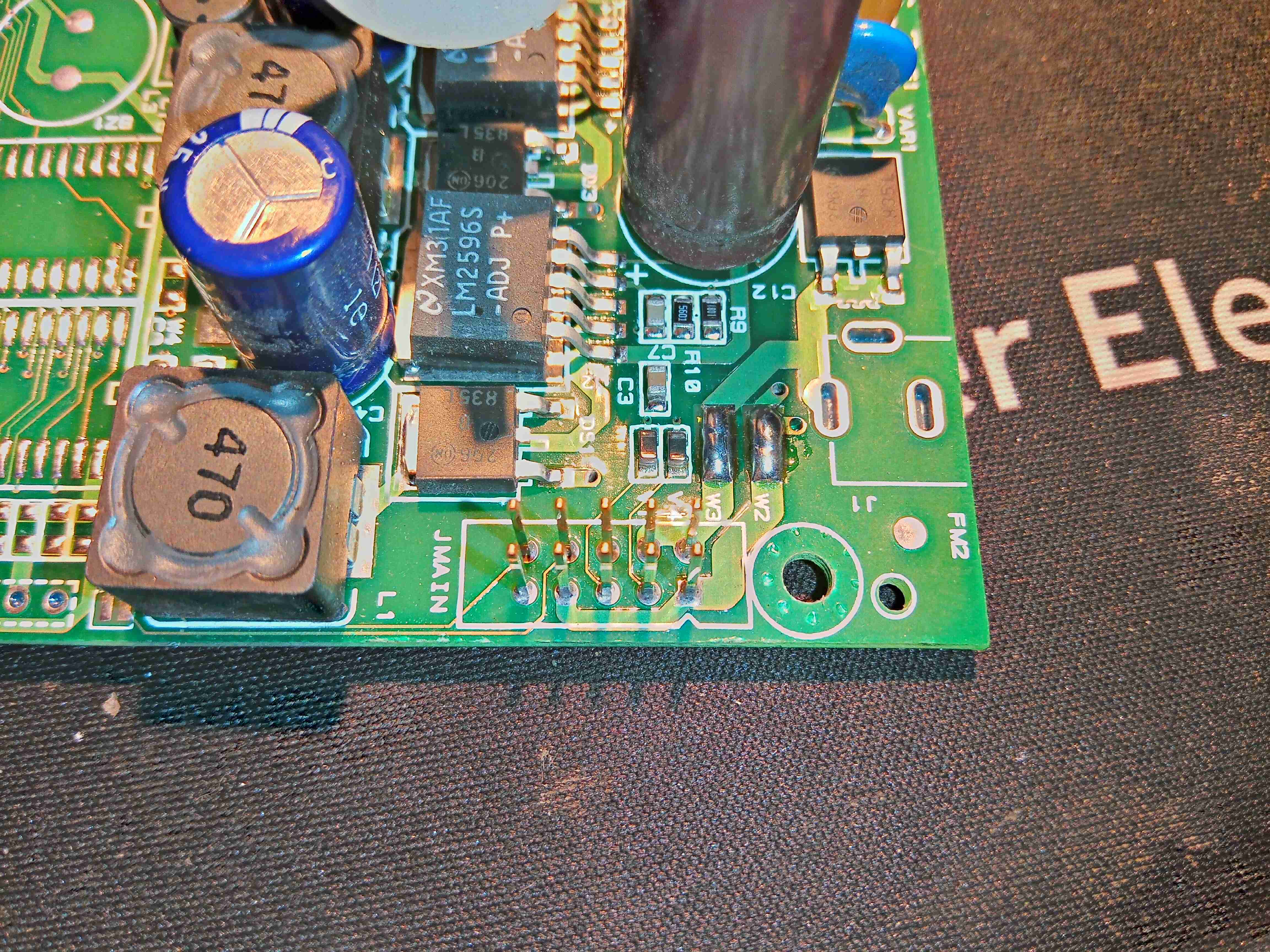
There’s two serial links on this board, driven from the main microcontroller – the primary one is on the connector marked JMAIN, along with the power input & a couple of other unknown signals.
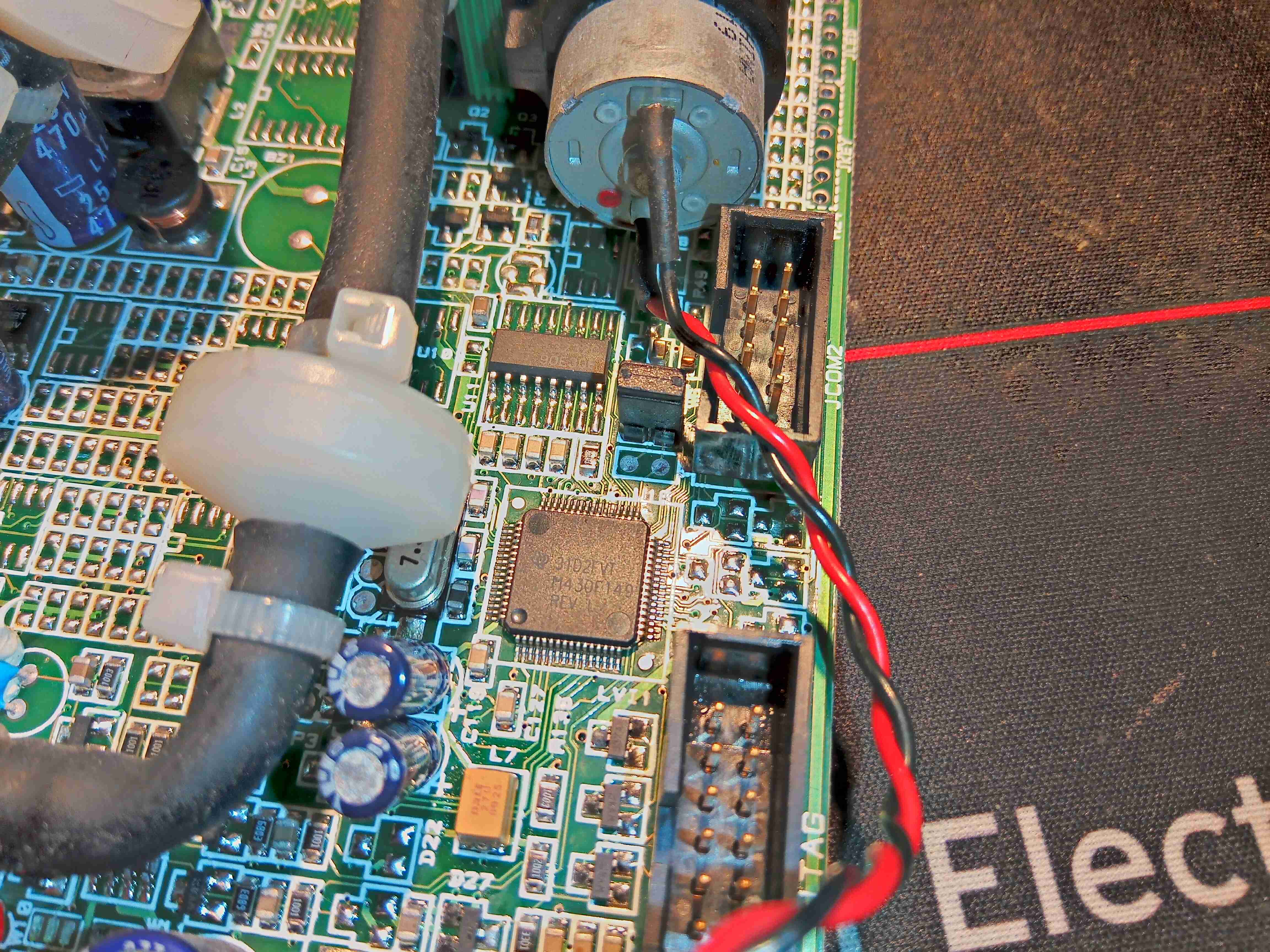
Over on the other side of the board is the brains of the operation – an MSP430 microcontroller, with an RS232 transceiver IC & another RS-232 port marked COM2. The remaining connector is a JTAG port for the micro.
Here’s the gas analyser cell itself, sandwiched under another board. There’s a temperature sensor on the side of the cell at the bottom, and even though there’s many pins on the header here, only a couple are actually used for the IR emitter.
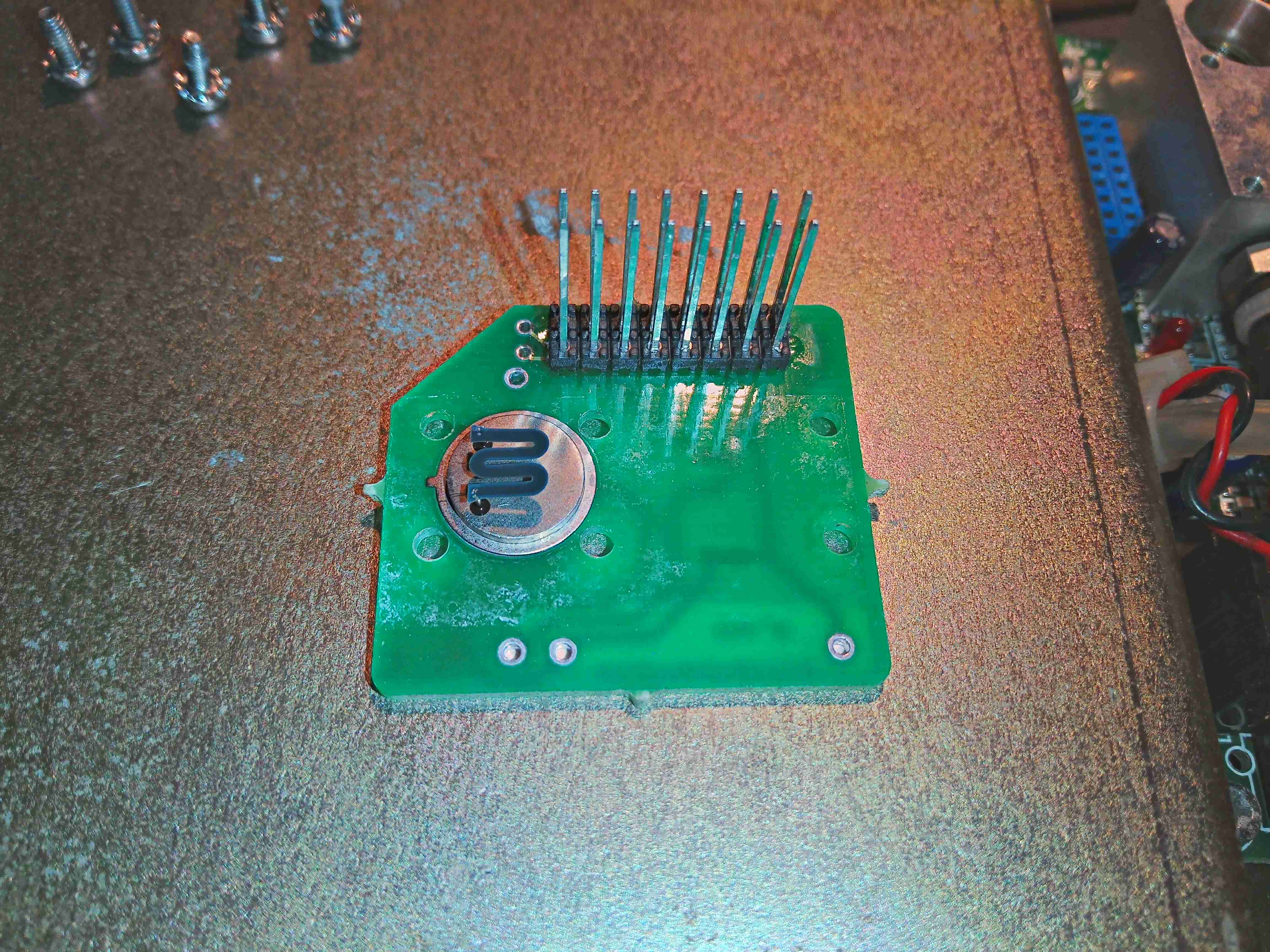
Removing the screws from the top allows the board to be removed, which exposes the Mid-IR emitter component with an exposed element. This looks to be very fragile, so I won’t be messing with this much. From metering the connections, this appears to be driven at about 2v from the microcontroller.
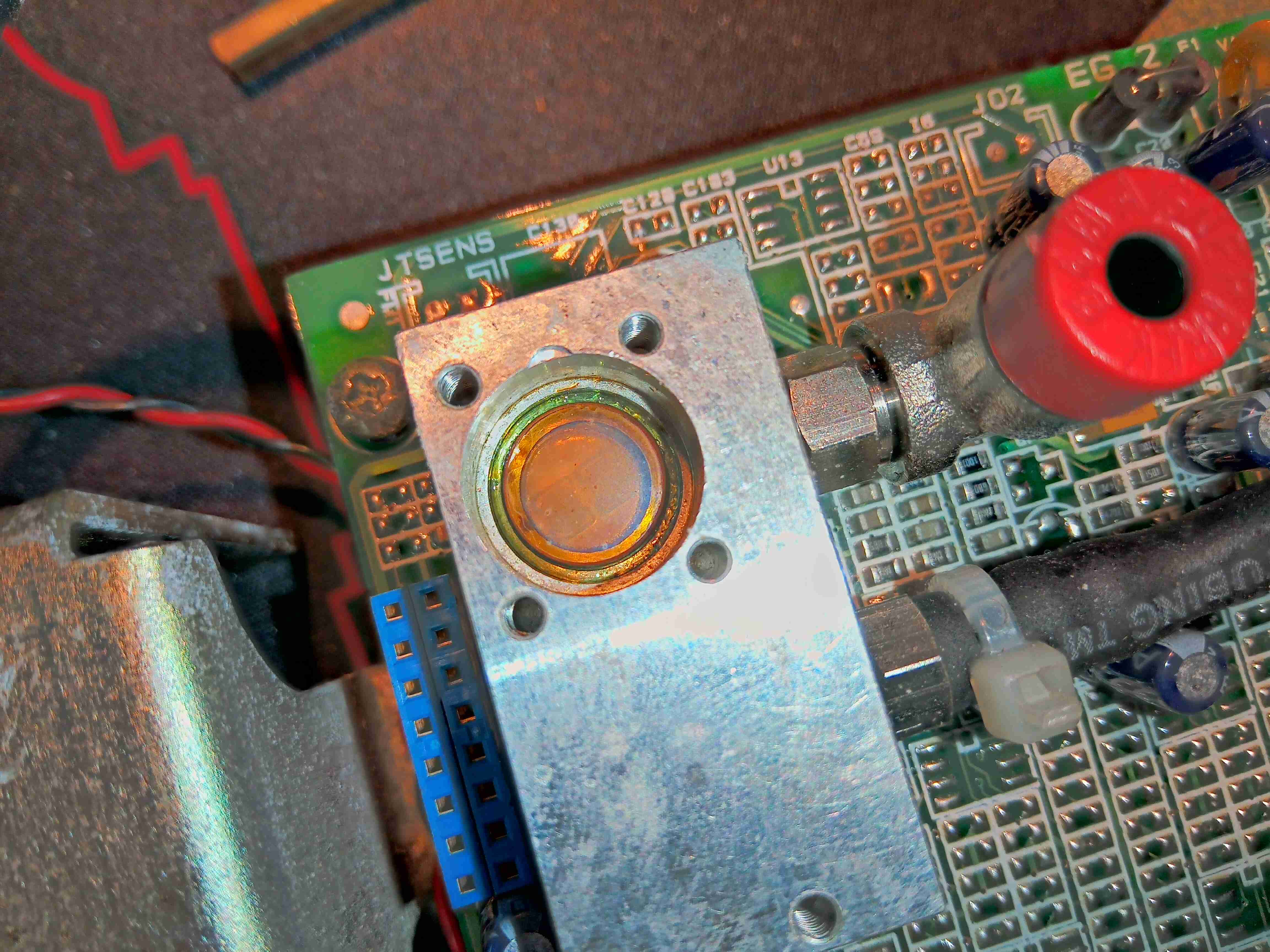
The window into the gas cell looks to be made of something exotic – considering the IR application & the colour, this is probably Zinc Selenide.
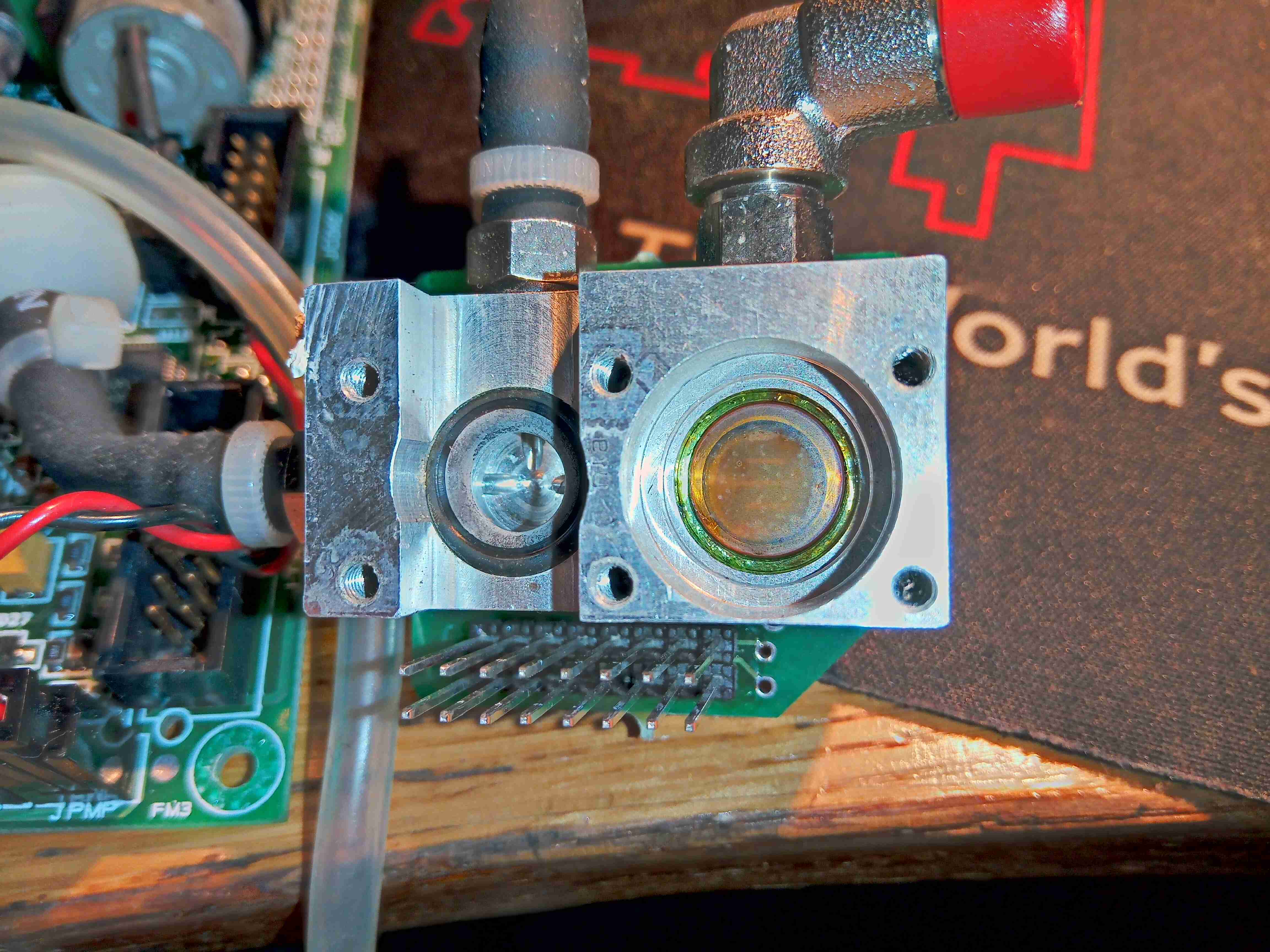
Removing some more screws on the bottom exposes the bottom of the cell with another IR window, and an O-Ring where a pressure sensor sits.
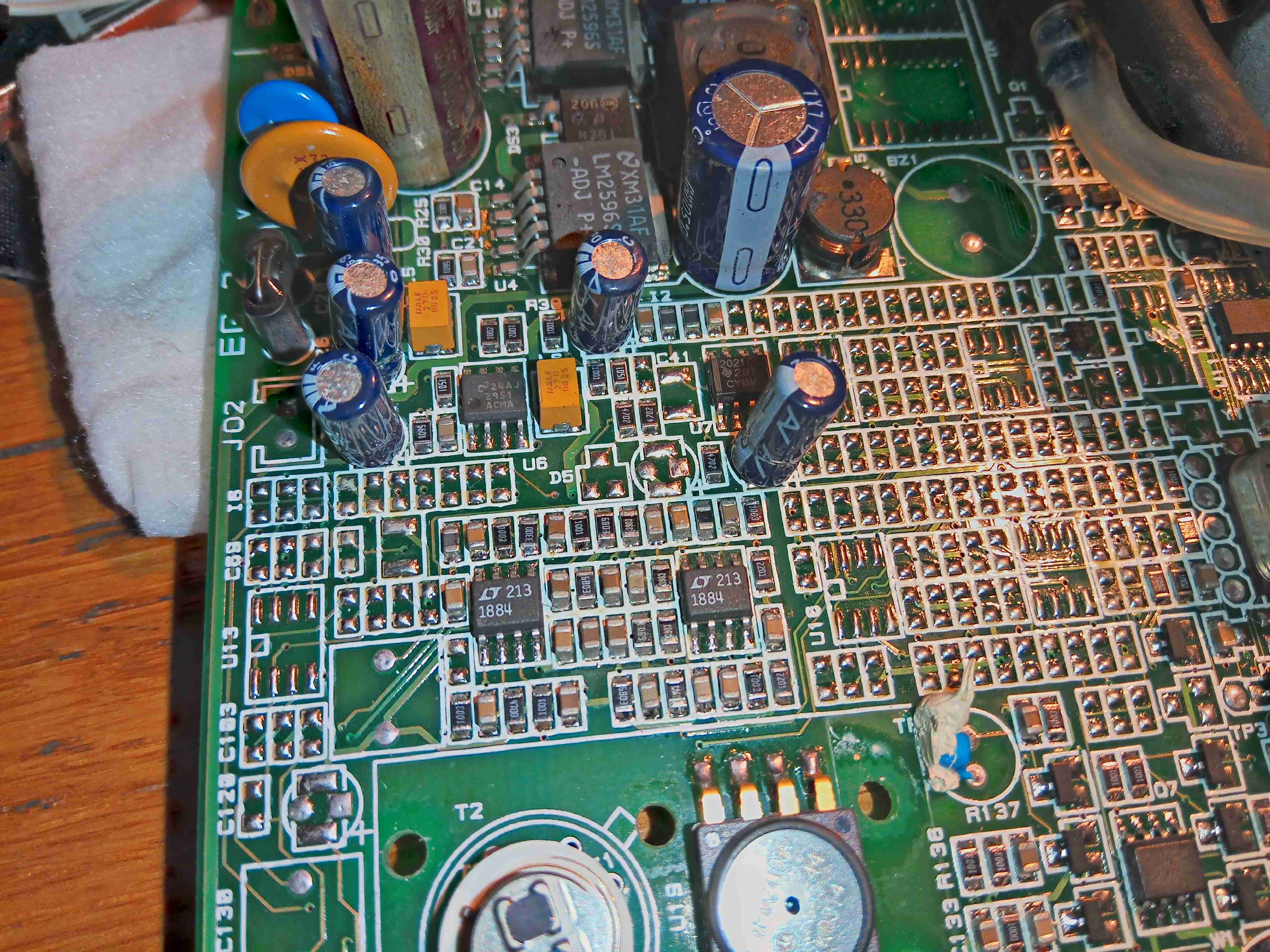
There’s a couple of very accurate LT1884 Rail-To-Rail Precision Op-Amps next to the cell, most likely used to measure the output from the sensor itself.
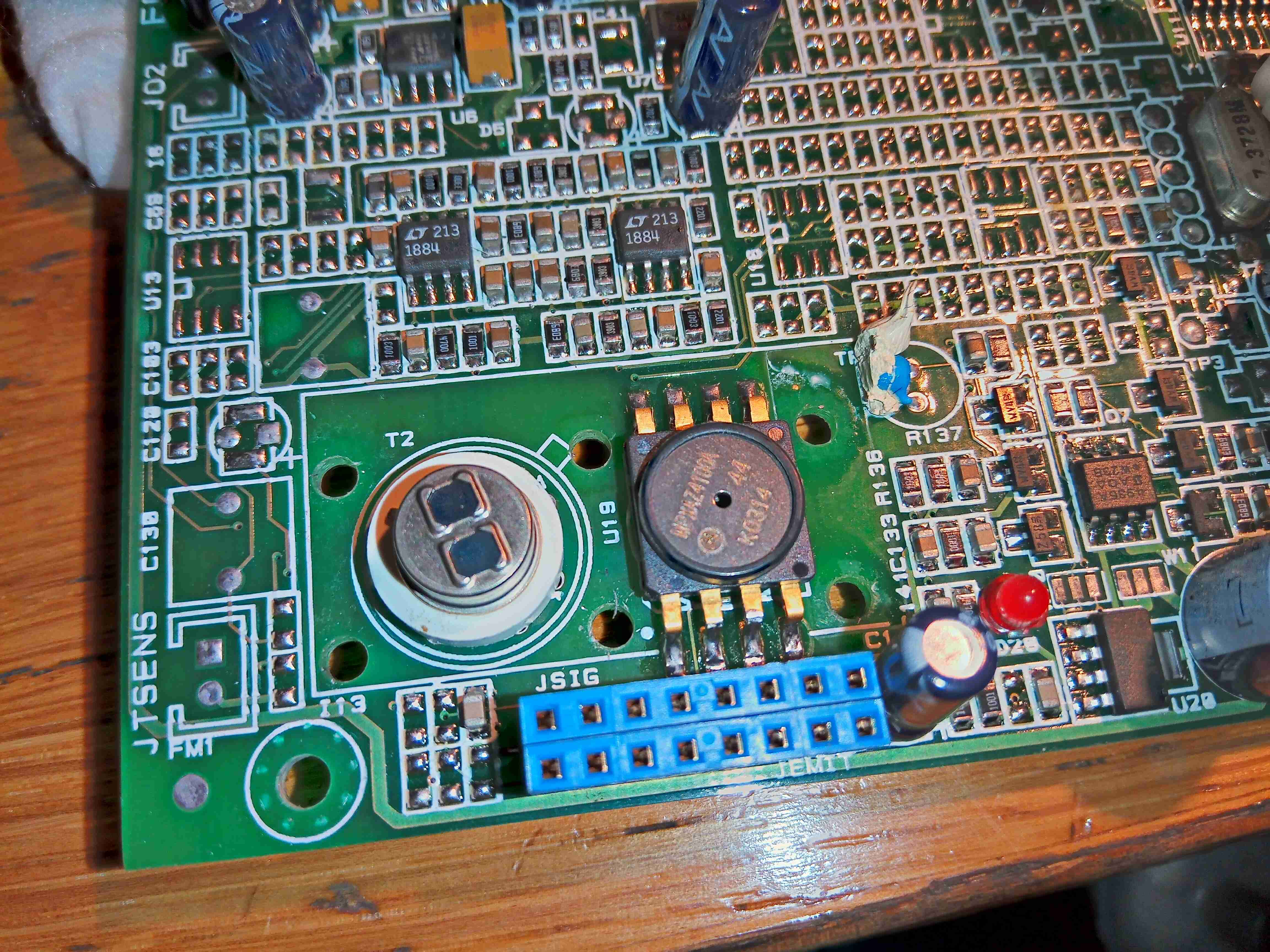
Finally, there is a dual-window thermopile sensor, and a pressure sensor. I wasn’t able to get any information on either of these, but I did find some ranges of sensors for Mid-IR measurement operations, that mentions a wavelength around 10µm for R-134a spectroscopy.
I will try to get this module going & measuring some gases, if I can work out how to talk to it – I already know the serial lines so it’s just working out a command set. If anyone has any information on these, please do get in touch! A service manual for the refrigerant machine this came out of would be good!
