Posted on Leave a comment

Amano PIX 3000x Timeclock

Front
Front

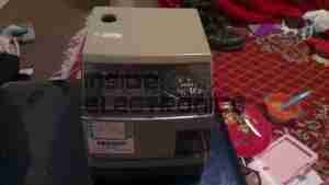
This is a late 90’s business timeclock, used for maintaining records of staff working times, by printing the time when used on a sheet of card.
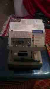
Front Internal
Front Internal

Here is the top cover removed, which is normally locked in place to stop tampering. The unit is programmed with the 3 buttons & the row of DIP switches along the top edge.
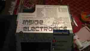
Instructions
Instructions

Closeup of the settings panel, with all the various DIP switch options.
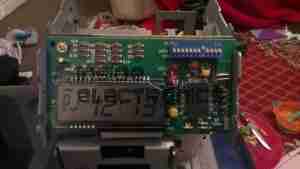
CPU & Display
CPU & Display

Cover plate removed from the top, showing the LCD & CPU board, the backup battery normally fits behind this. The CPU is a 4-bit microcontroller from NEC, with built in LCD driver.
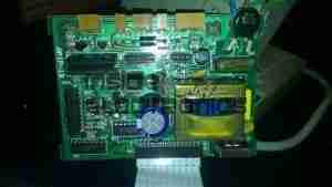
PSU & Drivers
PSU & Drivers

Power Supply & prinhead drivers. This board is fitted with several NPN Darlington transistor arrays for driving the dox matrix printhead.
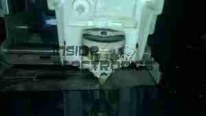
Printhead
Printhead

Printhead assembly itself. The print ribbon fits over the top of the head & over the pins at the bottom. The drive hammers & solenoids are housed in the circular top of the unit.
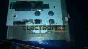
Printhead Bottom
Printhead Bottom

Bottom of the print head showing the row of impact pins used to create the printout.

2013-02-13 18.00.09Bottom of the solenoid assembly with the ribbon cable for power. There are 9 solenoids, to operate the 9 pins in the head.
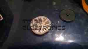
Return Spring
Return Spring

Top layer of the printhead assembly, showing the leaf spring used to hold the hammers in the correct positions.
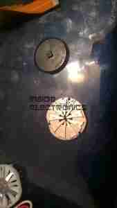
Hammers
Hammers

Hammer assembly. The fingers on the ends of the arms push on the pins to strike through the ribbon onto the card.

Solenoids
Solenoids

The ring of solenoids at the centre of the assembly. These are driven with 3A darlington power arrays on the PSU board.
Gearbox Internals
Gearbox Internals

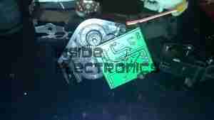
There is only a single drive motor in the entire unit, that both clamps the card for printing & moves the printhead laterally across the card. Through a rack & pinion this also advances the ribbon with each print.


Posted on 1 Comment

Brightwell Brightstar II BSL4 Dosing System

Overview
Overview
Overview

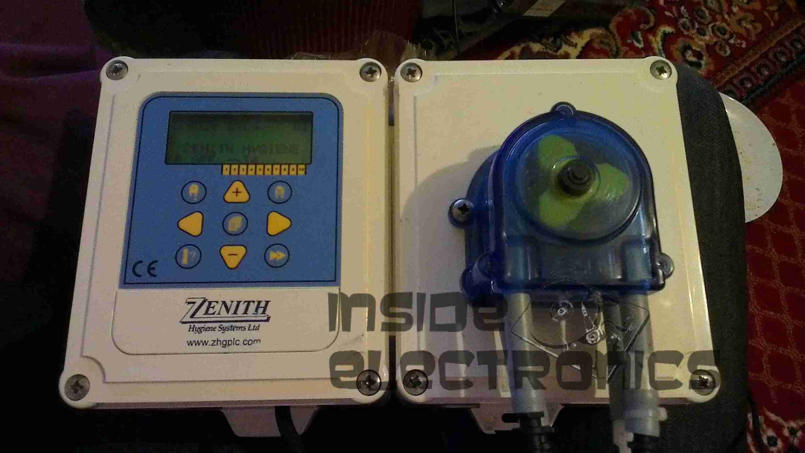
Here is an old chemical dosing system for industrial washing machines. These units are 4-pump models, with dual pumpheads. The motors are reversed to operate alternate pumps in the same head.

Label
Label

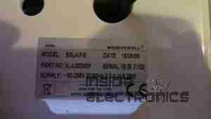
From 2006, this is a fairly old unit, and made in the UK.

CPU Board
CPU Board

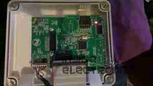
Main controller PCB, with interface to the power electronics via the ribbon cable, an external serial port for programming to it’s left. Powered by an ST microcontroller. The LCD is below this board.

PCU & Driver PCBs
PCU & Driver PCBs

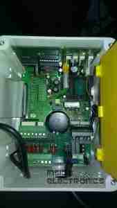
Main power supply, sense input & motor driver boards. The PSU outputs +5v, +12v & +24v. The inputs on the lower left connect to the washing machine & trigger the pumps via the programming on the CPU. The motors are driven by L6202 H-Bridge drivers from ST.

Motor Assembly
Motor Assembly

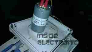
Motor & gearbox assembly on the back of the pumphead. These are 24v DC units with 80RPM gearboxes.

UPDATE:
As it seems to be difficult to find, here is the user manual for this unit:
[download id=”5557″]

Posted on Leave a comment

Belkin 2 Port KVM Switch

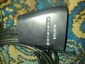
Main Body
Main Body

Here is an old type KVM switch, PS/2 & VGA interface.

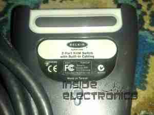
Label
Label

Details Label

Top Removed
Top Removed

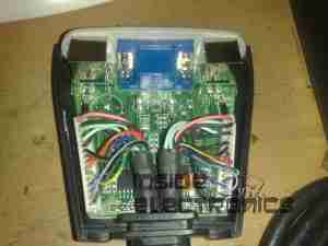
Top removed from the main body, the cables coming in from the bottom connect to the VGA, keyboard & mouse ports on the slave computers, the connectors at the top connect to the single monitor, keyboard & mouse.

PCB
PCB

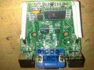
PCB removed from the body. This is driven by a PIC16C57C-04 microcontroller.
The pair of LEDs indicate which computer is using the peripherals at any one time.

Posted on 2 Comments

Epson Ink Cartridge Resetter

Interface
Interface

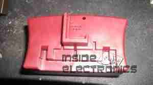
This is a device designed to reset Epson brand ink cartridges that are reportedly out of ink, so they again report full to the printer Here is the front of the unit, with the guide for attaching to a cartridge.

PCB Back
PCB Back

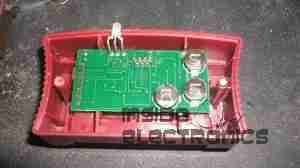
Back of the device removed. 3 button cells provide power to the PCB. Indicator LED sticks out of the top of the device for reset confirmation.
Row of pads on far left edge of the PCB are presumably a programming header for the uC on the other side of the board.

PCB Front
PCB Front

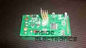
Here is the  front of the PCB, main feature being the grid of pogo pins to connect to the cartridge chip. IC on lower right of that is a MSP430F2131 uController, a Texas Instruments part.
The IC directly to the left of the pogo pin bed is a voltage regulator, to step down the ~4.5v of the batteries down to the ~3.3v that the uC requires.