I’ve always found programming repeaters into the UV-5R manually a bit of an arse, especially since the manual is pretty poor & very concise. Ringway Manchester have done a very good video detailing a simple way to get this done without a computer & most importantly, without any headaches!
Tag: computer
Raspberry Pi Update
Well I got my delivery info finally, the week commencing 28/05/2012. Experiments to come once I have it!
Coming Soon – Raspberry Pi
Coming soon! Unboxing of the Raspberry Pi & first experiments! Estimated start of June!

Rare Veroboard Design Tools – Stripboard Magic
Stripboard Magic
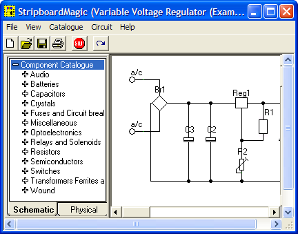
Stripboard Magic is a Windows application for designing PCB layouts on stripboard (aka prototyping board, aka Veroboard). It was released by a British company called Ambyr which ceased trading a long time ago.
The interface is a quite primitive and a little strange but the program is functional even on Windows XP. It also works great under wine in Linux, at least with version 0.9.38 and above as this is all I have checked. It should probably work on older versions too. I haven’t tried it on Vista though.
It can be a handy program when called upon and I have successfully used it a few times when throwing together random small circuits. Due to the interface I would imagine it to be a bit clumsy for very large circuits. The biggest gripe I have with it is the inability to change the orientation of components on the board, so some circuits tend to be slightly larger than they need to be.
I downloaded a copy of Stripboard Magic 1.0 back in the 90’s and recently just found it lying about on my computer. As I would consider it to well and truly be abandonware and as it seems to be a little sought after by some hobbyists I have provided a link to download it below.
[download id=”5624″]
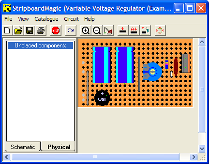
Here are some screenshots showing the schematic view (top) and board layout view (bottom):
Stripboard Designer
Another hard to find app these days is Stripboard Designer, mirrored here for people who wish to use it.
[download id=”5626″]
[download id=”5628″]
Belkin 2 Port KVM Switch

Here is an old type KVM switch, PS/2 & VGA interface.

Details Label

Top removed from the main body, the cables coming in from the bottom connect to the VGA, keyboard & mouse ports on the slave computers, the connectors at the top connect to the single monitor, keyboard & mouse.

PCB removed from the body. This is driven by a PIC16C57C-04 microcontroller.
The pair of LEDs indicate which computer is using the peripherals at any one time.
Logitech Cordless Ball Mouse

This is an old legacy wireless mouse from Logitech. This uses a ball rather than optical technology.

Bottom of the mouse, showing the battery cover & the mouse ball.

Top removed from the mouse, showing the PCB inside. The smaller PCB on the left supports the microswitches for the buttons & mouse wheel.

Closeup of small PCB showing the microswitches & the IR LED & phototransistor pair for the mouse wheel encoder.

View of main PCB, with interface IC lower right. Pair of quartz crystals provide clocking for the transmitter & internal µC.
Battery contacts are on lower left of the PCB. At the top are the IR pairs for the X & Y axis of the mouse ball.

Closeup of the pairs of IR LEDs & phototransistors that make up the encoders for X/Y movement of the mouse, together with the slotted wheels in the mouse base that rotate with the ball. Steel wire around the smaller PCB is the antenna.
Current Cost ‘Envi’ CC128 Power Meter

This is the Current Cost CC128 Real Time Power Meter. Shown here is the display unit, British Gas issued these free to some customers.
This unit measures current power draw in Watts, cost of power currently being used (requires unit price to be set), overall kWh usage over the past 1, 7 or 30 days & power trends during the day, night & evening. Also displays current time & current room temperature.

Here the front panel of the display has been un-clipped. At the bottom are the RJ-45 serial port & power connections.
This unit uses a PIC micro-controller as it’s CPU (PIC18F85J90) Just above & left of the CPU is the 433MHz SPD radio receiver module. The chips on the right of the CPU are a 25LC128 SPI serial EEPROM for data storage & a 74HC4060 14 stage binary counter, to which is connected the 32kHz clock crystal. The red wire around the top of the display is the antenna for the radio receiver.
For more info on the CC128 in general, the serial port & software for computer data logging, see this link
See this link for Current Cost’s list of software

Closeup of the ICs on the mainboard.

Here we have the transmitter unit, with Current Transformer (CT). The red clamp fits around one of the electric meter tails & read the current going to the various circuits. This unit is powered by 2x D cells, rated at a life of 7 years.

The PCB inside the transmitter. Again very minimal design, unknown controller IC, 433MHz radio transmitter on right hand side with wire antenna. Two barrel connectors on left hand side of board allow connection of up to two more CT clamps for measurement of 3-phase power. Centre of board is unmarked header. (ICSP?)

CT unit. Inside is a coil of wire & an iron core which surrounds the cable to be measured.
| PIC18F85J90 |
