Posted on Leave a comment

HPI Nitrostar F4.6 Ignition Conversion

As there was no other online example of someone converting a glow/nitro car engine onto CDI ignition, I thought I would document the highlights here.
The engine is currently still running on glow fuel, but when the required fuel lines arrive I will be attempting the switch over to 2-Stroke petrol mix. This should definitely save on fuel costs.

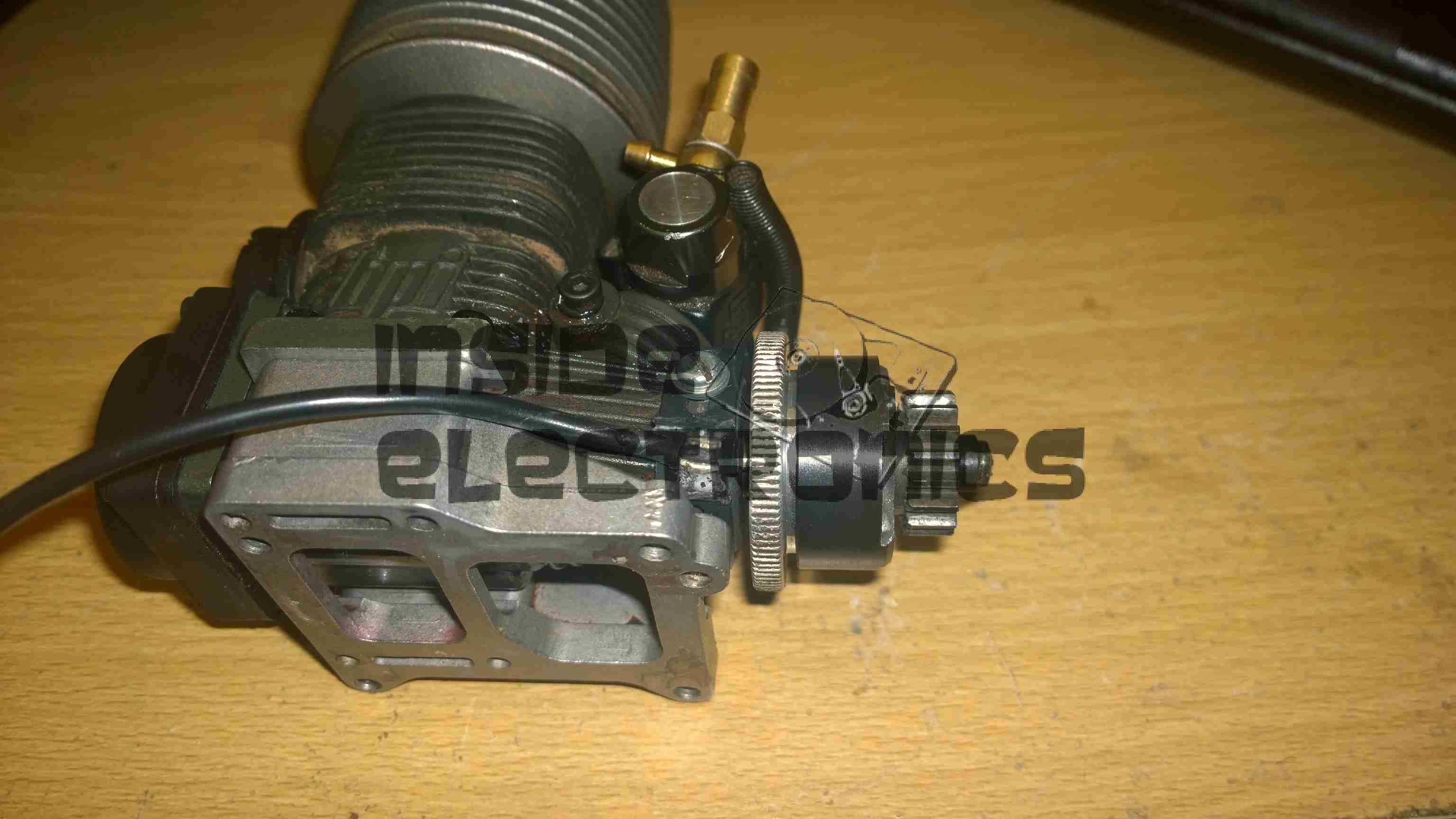
The engine in this case is a HPI NitroStar F4.6 nitro engine, from a HPI Savage X monster truck.

F4.6 Engine
F4.6 Engine

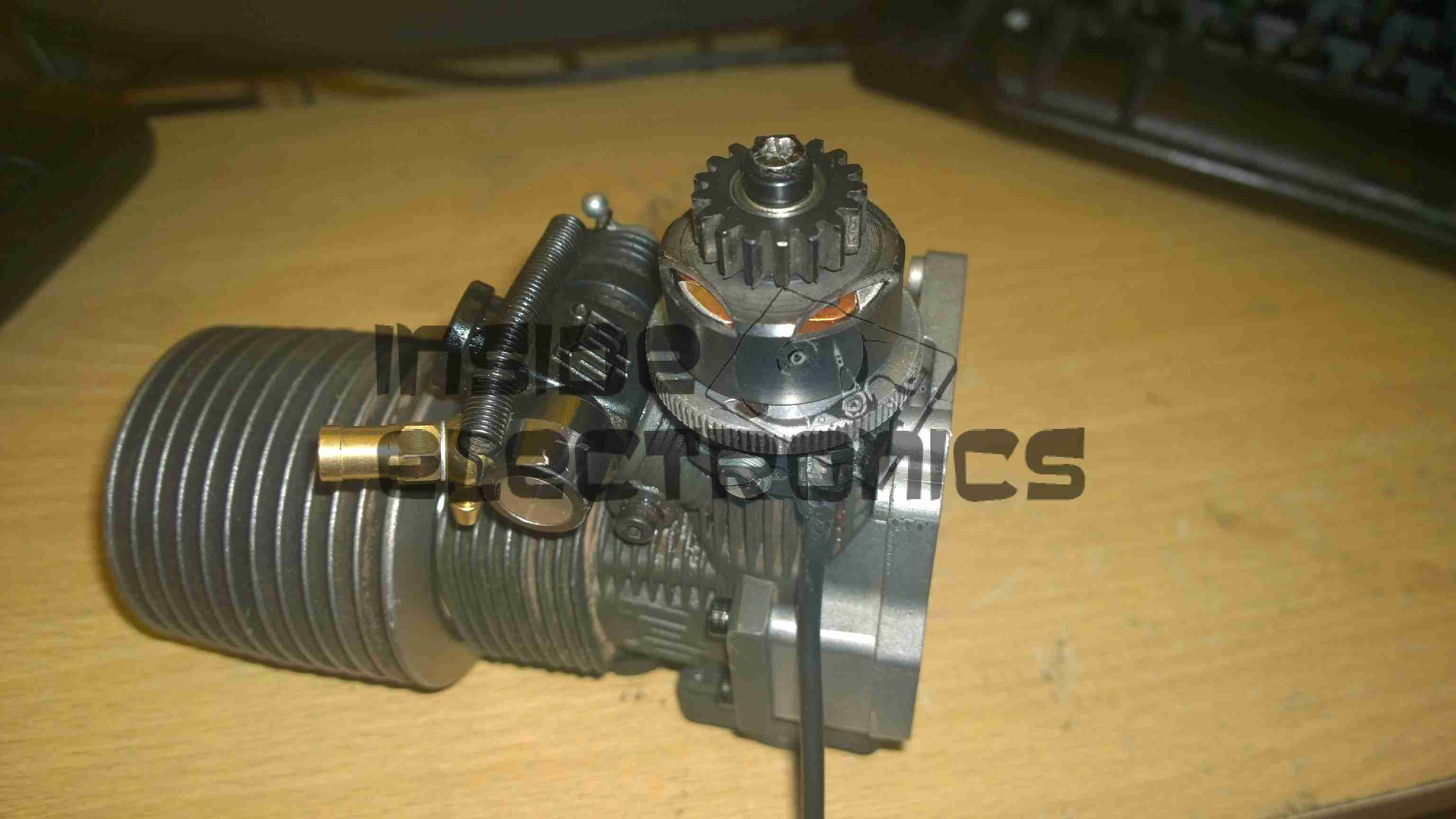
Above is the converted engine with it’s timing sensor. As The installation of this was pretty much standard, a complete strip down of the engine was required to allow the drilling & tapping of the two M3x0.5 holes to mount the sensor bracket to. The front crankshaft bearing has to be drifted out of the crankcase for this to be possible.

Ignition Hall Sensor

Detail of the ignition hall sensor. The bracket has to be modified to allow the sensor to face the magnet in the flywheel. Unlike on an Aero engine, where the magnet would be on the outside edge of the prop driver hub, in this case the hole was drilled in the face of the flywheel near the edge & the magnet pressed in. The Hall sensor is glued to the modified bracket with the leads bent to position the smaller face towards the back of the flywheel.
The clearance from the magnet to sensor is approx. 4mm.

Flywheel Magnet
Flywheel Magnet

Detail of the magnet pressed into the flywheel. A 3.9mm hole was drilled from the back face, approx 2mm from the edge, & the magnet pressed into place with gentle taps from a mallet & drift, as I had no vice to hand.
Initial timing was a little fiddly due to the flywheel only being held on with a nut & tapered sleeve, so a timing mark can be made inside the rear of the crankcase, across the crank throw & case to mark the 28 degree BTDC point, the flywheel is then adjusted to make the ignition fire at this point, before carefully tightening the flywheel retaining nut to ensure no relative movement occurs.
The slots in the sensor bracket allow several degrees of movement to fine adjust the timing point once this rough location has been achieved.

1/4"-32 Spark Plug
1/4″-32 Spark Plug

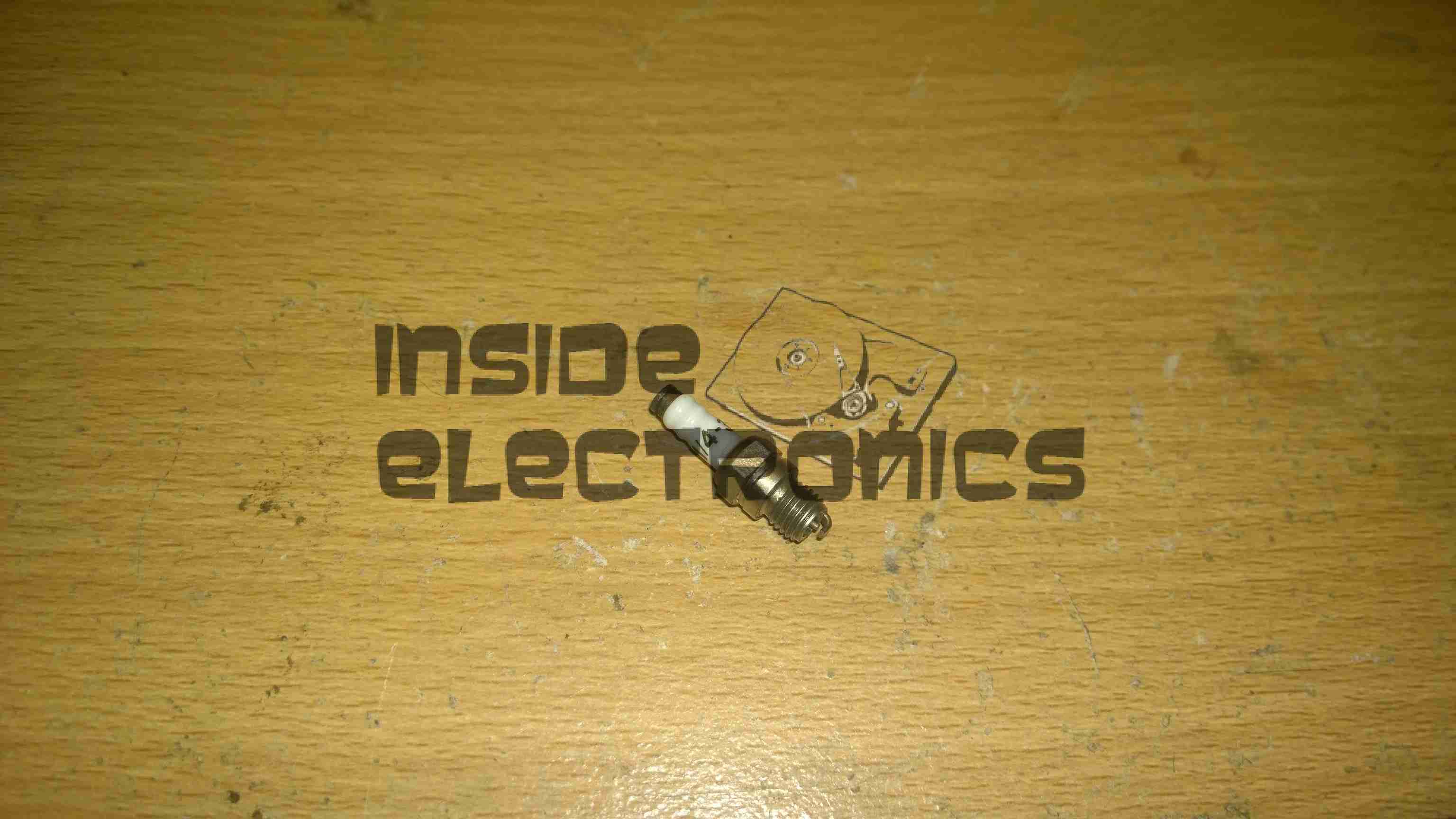
Definitely the tiniest spark plug I’ve ever seen, about an inch long. Some trouble may be encountered with this on some engines – the electrodes stick out about 2mm further into the combustion chamber than a standard glow plug does. This causes the ground electrode to hit the top of the piston crown. (This happens on the HPI NitroStar 3.5 engine). The addition of another copper washer under the plug before tightening should cure this problem.

RcExl CDI Ignition Module

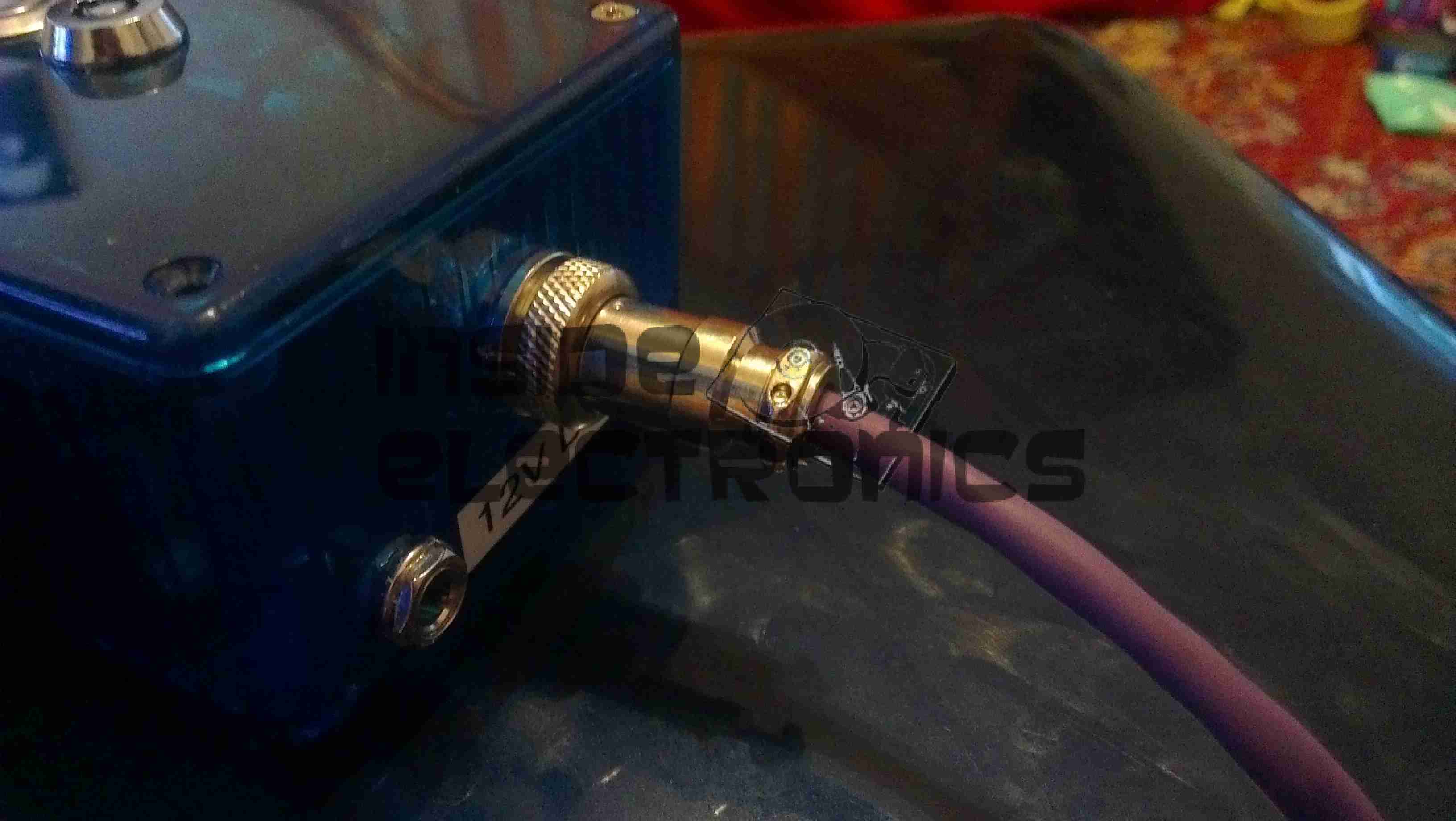
Ignition module. Due to the depth of the plug in the heatsink head on these engines, I will have to modify the plug cap to straighten it out, as it will not fit in this configuration.
However, ignition modules are available from HobbyKing with straight plug caps, this makes modification unnecessary

The ignition & components used on this system were obtained from JustEngines.

Posted on Leave a comment

Datakom DKG-171

Front
Front

Here is a teardown of the Datakom DKG-171 generator transfer controller. Here is the front of the unit, with the pictogram of the system, the indicator LEDs & the generator test button.


Rear
Rear

The rear of the unit features the connection points for the mains, generator & generator control I/O.

PCB Rear
PCB Rear

Rear of the PCB with the control relays. The two larger relays switch in the remote contactors to switch the mains supply over between the grid & the generator, while the smaller relay switches 12v power out to a terminal to automatically start the generator.

PCB Front
PCB Front

Front of the PCB with the control logic & main PIC microcontroller.


Posted on 1 Comment

AVR Optical Tachometer

Here is an AVR powered optical tachometer design, that I adapted from the schematic found here.

I made a couple of changes to the circuit & designed a PCB & power supply module to be built in. The original design specified a surface mount IR LED/Photodiode pair, however my adjustment includes a larger IR reflectance sensor built onto the edge of the board, along with a Molex connector & a switch to select an externally mounted sensor instead of the onboard one.

There is also an onboard LM7805 based power supply, designed with a PCB mount PP3 battery box.
The power supply can also be protected by a 350mA polyfuse if desired. If this part isn’t fitted, then a pair of solder bridge pads are provided within the footprint for the fuse to short out the pads.

For more information on the basic design, please see the original post with the link at the top of the page.

Schematic
Schematic

Here is an archive of the firmware & the Eagle CAD files for the PCB & schematic design.


Posted on Leave a comment

Wearable Raspberry Pi – Some Adjustments

USB Hub
USB Hub

As the first USB hub I was using was certainly not stable – it would not enumerate between boots & to get it working again would require waiting around 12 hours before applying power, it has been replaced. This is a cheapie eBay USB hub, of the type shown below.

These hubs are fantastic for hobbyists, as the connections for power & data are broken out on the internal PCB into a very convenient row of pads, perfect for integration into many projects.

Breakout Hub
Breakout Hub

I now have two internal spare USB ports, for the inbuilt keyboard/mouse receiver & the GPS receiver I plan to integrate into the build.

These hubs are also made in 7-port versions, however I am not sure if these have the same kind of breakout board internally. As they have the same cable layout, I would assume so.


Connector Panel
Connector Panel

Here is a closeup of the back of the connectors, showing a couple of additions.

I have added a pair of 470µF capacitors across the power rails, to further smooth out the ripple in the switching power supply, as I was having noise issues on the display.

Also, there is a new reset button added between the main interface connectors, which will be wired into the pair of pads that the Raspberry Pi has to reset the CPU.
This can be used as a power switch in the event the Pi is powered down when not in use & also to reset the unit if it becomes unresponsive.


Posted on Leave a comment

445nm Laser TTL Interface

TTL Interface
TTL Interface

In preparation for my laser scanner project, I have modified my existing 445nm laser to accept a TTL blanking input. The laser driver is already enabled for this & just required an extra connection to interface with my laser scanner showboard. I have used an 8-pin connection to allow the same cable & interface to be used with an RGB laser system, when it arrives. The signals are as follows, from top centre, anti-clockwise:

Pin 1: +12v Power
Pin 2: Blue TTL
Pin3: GND
Pin 4: Green TTL
Pin 5: GND
Pin 6: Red TTL
Pin 7: GND
Centre: Power GND


Custom TTL Cable
Custom TTL Cable

Here is the custom 8 core cable, which connects to the laser scanner show board. This cable allows the laser to be used for projection while still retaining the portable function & the keylock arming switch. When plugged in the cable bypasses the keyswitch & provides 12v DC direct to the laser driver.

Posted on Leave a comment

Site Hosting

Original Rack
Original Rack

There have been quite a few updates to the hosting solution for this site, which is hosted locally in my house, from the above setup, in a small comms rack, to a new 22U half rack, with some hardware upgrades to come.

Core Switch Disconnected

Core switch here has been removed, with the rest of the core network equipment. The site was kept online by a direct connection into the gateway to the intertubes.

Switching Gear Installed

New 22U rack, with the core switch, FC switch & management & monitoring server installed.

Router Going In
Router Going In

As I had no rack rails to start with, the servers were placed on the top of the rack to start off, here is the Dell PowerEdge 860 pfSense core router installed, with the initial switch wiring to get the internal core network back online. This machine load balances two connections for an aggregated bandwidth of 140MB/s downstream & 15MB/s upstream.
The tower server behind is the NAS unit that runs the backups of the main & auxiliary webservers.

Almost Done
Almost Done

Still with no rack kits, all the servers are placed on top of the rack, before final installation. This allows running of the network before the rest of the equipment was installed.

The main server & aux server are HP ProLiant DL380 G3 servers, with redundant network connections.

Still to arrive are the final rack kits for the servers & a set of HP BL20p Blade servers, which will be running the sites in the future.

Stay tuned for more updates as they happen!

Posted on 1 Comment

Velleman MK179

Completed Kit
Completed Kit

This is the Velleman MK179 Proximity Card Reader, which is supplied in kit form. In the image above you can see the completed kit, the read coil is etched onto the black PCB on the left. Bringing a recognised card close to the coil operates the relay on the main PCB for a programmable amount of time.

Main PCB
Main PCB

Closeup of the main PCB, 12v DC input at top right. Left IC is an LM358 dual Op-Amp, the IC on the right is a PIC12F629 with Velleman’s custom firmware.
Logic power is supplied to the ICs & the oscillator from the LM7805 regulator at the top of the PCB. The relay is a standard 15A SPDT 12v coil relay, with the switch contacts broken out onto the screw terminals on the left.

Schematic Diagram
Schematic Diagram

As it is not provided with the kit, unlike other Velleman kits, here is the schematic for this.


Posted on Leave a comment

PSi 150 Power Inverter

Front
Front

This is a small 120W power inverter, intended for small loads such as lights, fans, small TVs & laptop computers.

End Cover
End Cover

End cover of the unit, 12v DC input cord at the top, power switch & indicator LEDs at the bottom.

Mains Output
Mains Output

Opposite end of the unit, with the standard 240v AC 50Hz Mains output socket.

Cover Removed
Cover Removed

Cover removed from the top of the unit. Main power transformer is visible in the centre here, MOSFET bank is under the steel clamp on the left, the aluminium case forms the heatsink.

PWM Controllers
PWM Controllers

On the right is a KA3525 switchmode PWM controller & on the left is a LM324N quad Op-Amp IC. The buzzer on the far left is for the low battery warning.

PCB Removed
PCB Removed

PCB removed from the casing, with the MOSFET bank on the right hand side. Two potentiometers in the centre of the board tweak the frequency of the switcher & the output voltage.


Posted on Leave a comment

BigBen DSi Inductive Charging Dock

Front
Front

Here is a Inductive charger designed for the Nintendo DSi. Cheap Chinese build, but it does work!

Overview
Overview

Top has been removed from the unit here. Most prominent in the centre is a solid steel bar, simply there to give the device some weight.
Pair of Tri-colour LEDs at the front indicates charging status.
Induction coil is on the left, with the controller & oscillator PCB at the top.

PCB Closeup
PCB Closeup

Closeup of the PCB, ICs have had their markings ground off.

Coil
Coil

Induction coil. This couples power into a coil built into a special battery, supplied with the base, to charge it when the DSi is placed on the dock.

Label
Label

Information Label on the base.

Power Input
Power Input

Standard DSi charger port, connects to the charger you get with the DSi. Power switch is on the right.

Posted on Leave a comment

Sanyo Talkbook VAS

Front
Front

Here is a Sanyo tape recorder, with built in voice activation. Takes standard audio cassettes.
Here visible is the speaker on the left, microphone is on the right of the tape window. The tape counter is at the top.

Back Removed
Back Removed

Back cover removed from the unit, showing the PCB & the connections. The IC is the controller/amplifier.

PCB
PCB

Top of the PCB, control switches, volume potentiometer & microphone/headphone sockets on the right. DC power jack top left. Switch bottom centre senses what mode the tape drive is in.

Tape Deck
Tape Deck

Rear of the tape deck, main drive motor is bottom right, driving the capstan through a drive belt. This drives the tape spools through a series of gears & clutches. Belt going to top left drives the tape counter.

Drive
Drive

Front of the tape drive. Read/write head is top centre. Blue head is bulk erase head used during recording.

Speaker
Speaker

Main speaker. 8Ω 0.25W.

Counter
Counter

Simple mechanical tape counter.

Posted on 1 Comment

Combo Microwave

Electronics Bay
Electronics Bay

Here are the internals of a cheap Microwave/Convection Oven combo. Electronics bay is pretty much the same as a standard microwave, with the magnetron, transformer & diode/capacitor voltage doubler, with the addition of an extra fan & a pair of nichrome elements to provide the convection oven function.

Convection Fan
Convection Fan

Convection blower which keeps the cooking vapours & smoke away from the elements, & circulates the hot air around the cooking chamber. This is a 12v DC centrifugal type blower.

Convection Element
Convection Element

The elements are inside this steel shield, air duct extends from the centre.

Thermal Cutouts
Thermal Cutouts

This oven has a pair of thermal switches on the magnetron.

Capacitor & Diode
Capacitor & Diode

The usual capacitor/diode voltage doubler in the magnetron power supply. The transformer is visible to the left.

Controller
Controller

Electronic controller PCB. This has a pair of relays that switch the elements & the magnetron transformer.

Posted on Leave a comment

Grand Hand View

Front
Front

This is an adaptor to convert computer VGA to composite & S-Video output for a normal TV.

Bottom
Bottom

Bottom of the unit with option select switch.

PCB Top
PCB Top

PCB removed from the casing, CPU in centre, buffer RAM on the right.

PCB Bottom
PCB Bottom

Reverse side with the VGA connections at the top & the S-Video/composite outputs on the bottom.

VGA
VGA

Inputs. USB connector provides power, pair of VGA connectors provides passthrough function.

S-Video & Composite
S-Video & Composite

Outputs. Standard S-Video on the left & composite video on the right.

Posted on Leave a comment

Xbox 360 HD A/V Cable

Connectors
Connectors

Teardown of the Xbox 360 HD A/V cable. Standard Xbox connector on the left. Component video/audio/composite video connectors on the right.

Internals
Internals

Internals of the Xbox connector. Black unit is fiber optic audio connector, PCB underneath holds the HD/SD video switch.

Posted on Leave a comment

Window Break Alarm

Front
Front

Cheap unbranded window break alarm. Here is the front of the unit, with the sounder at the top, Power/sensitivity switch at the right. Battery test button at the left.

Rear
Rear

Rear of the device, with the adhesive pad used to attach it to a window.

Internals
Internals

Front cover removed, showing the batteries, PCB & the sounder.

PCB
PCB

PCB removed from the casing, showing the remaining components.

Posted on Leave a comment

£1 Shop LED Glitter Lamp

LED Glitter Lamp
LED Glitter Lamp

This is a decorative lamp from the £1 shop. Inside are RGB LEDs.

Internals
Internals

Internals removed from the base of the unit. The 3 LEDs are visible on the top & the tilt activation switch on the edge of the PCB.

IC
IC

Side of the PCB with the RGB controller IC, which is under a blob of epoxy.

Battery Holder
Battery Holder

Reverse side of the PCB, showing the battery holder & the tilt switch. This runs on 3 button cells.

Posted on 4 Comments

Audi TT Roof Hydraulics

Pump
Pump

This is the hydraulic system from an Audi TT that would power the soft top. Here is the hydraulic pump unit. Oil Tank is on the left. Power is 12v DC at ~20A

Cylinders
Cylinders

The pair of hydraulic cylinders that attached to the roof mechanism.

Limit Switch
Limit Switch

One of the cylinders has a limit switch built in. The brass bolt coming out of the side of the head is one contact. The other contact is the cylinder body.

Hose
Hose

Marking on the hoses. This is Parker Polyflex hydraulic hose. 1/8″ ID.

Motor
Motor

Drive motor for the hydraulic pump. Standard DC permanent magnet motor.

Motor Suppression
Motor Suppression

Motor power terminals & suppression capacitors. As the reversing relays actually short the motor out when de-energized, there is a lot of arcing at the brushes without some suppression.

Reversing Relays
Reversing Relays

Reversing relay stack. Each relay is a SPDT configuration. The pair are arranged as a DPDT bank to reverse the motor, depending on which relay is energized.

Tank
Tank

Detail of the oil tank showing the level markings.

Power Valve
Power Valve

Solenoid valve on top of the unit. This valve provides full pump pressure to the cylinders when energized.

Posted on Leave a comment

Laser Diode Driver

Connection

Closeup
Closeup

The parts arrived for my adjustable laser diode driver! Components here are an LM317K with heatsink, 100Ω 10-turn precision potentiometer, 15-turn counting dial & a 7-pin matching plug & socket.

Driver Schematic
Driver Schematic

Here is the schematic for the driver circuit. I have used a 7-pin socket for provisions for active cooling of bigger laser diodes. R1 sets the maximum current to the laser diode, while R2 is the power adjustment. This is all fed from the main 12v Ni-Cd pack built into the PSU. The LM317 is set up as a constant current source in this circuit.

Installed
Installed

Here the power adjust dial & the laser head connector have been installed in the front panel. Power is switched to the driver with the toggle switch to the right of the connector.

Regulator
Regulator

The LM317 installed on the rear panel of the PSU with it’s heatsink.

Connection
Connection

Connections to the regulator, the output is fully isolated from the heatsink & rear panel.

Posted on Leave a comment

Portable Power Supply

Battery
Battery

This is detailing my portable multi-purpose power pack of my own design. Here is an overview, mainly showing the 4Ah 12v Ni-Cd battery pack.

Front Panel Right
Front Panel Right

Panel Features – Bottom: Car cigar lighter socket, main power keyswitch. Top: LED toggle switch, provision for upcoming laser project, Red main Power LED, 7A circuit breaker.

Front Panel Left
Front Panel Left

Top: Toggle switch serving post terminals, USB Port.
Post terminals supply unregulated 12v for external gadgets. USB port is standard 5v regulated for charging phones, PDAs etc.
Bottom: Pair of XLR connectors for external LED lights. Switches on their right control power & the knob controls brightness.

Additions are being made to this all the time, the latest being a 2W laser diode driver. Update to come soon!

Posted on 1 Comment

Co-Op Bank Card Reader

Keypad
Keypad

This is a little security measure you get with Internet Banking with the Co-Op, generates codes to confirm your identity using your bank card. About the size of a pocket calculator, this is the keypad & screen.

Card Slot
Card Slot

The rear of the unit, the card slots into the top, manufactured by Gemalto Digital Security.

Card Contacts
Card Contacts

Outer back cover removed, showing the 8 contacts for the chip on the bank card, the 2 contacts below that switch on power when a card is inserted. Power comes from 2 lithium coin cells in the compartment on the lower left.

PCB Rear
PCB Rear

PCB removed from the casing, showing the internal components. Two large pads at top left are battery connections, while the only IC on the board is the main CPU, under the card connector. 6MHz oscillator & 32Khz crystal on board for processing & timekeeping. LCD screen connection at far right.

Keypad Contacts
Keypad Contacts

Reverse side of the PCB, with the keypad contacts. LCD on right, with programming interface pads at side of keypad.

Posted on Leave a comment

Belkin F5U021 4-Port USB Hub

Top
Top

This is an old USB 1.1 hub that was recently retired from service on some servers. Top of the unit visible here.

Bottom Label
Bottom Label

Bottom label shows that this is a model F5U021 hub, a rather old unit.

PCB Front
PCB Front

PCB is here removed from the casing, Indicator LEDs along the bottom edge of the board, power supply is on the left. Connectors on the top edge are external power, USB host, & the 4 USB outputs. Yellow devices are polyswitch fuses for the 500mA at 5v each port must supply.

USB Hub IC
USB Hub IC

This is the USB Hub Controller IC, which is a Texas Instruments TUSB2046B device. Power filter capacitors next to the USB ports are visible here also, along with 2 of the polyswitches.

Power Supply
Power Supply

The power supply section of the unit, which supplies regulated 5v to the ports, while supplying regulated 3.3v to the hub controller IC. Large TO-220 IC is the 5v regulator. Smaller IC just under the power selector switch is the 3.3v regulator for the hub IC. The switch selects between Host powered or external power for the hub.

Posted on Leave a comment

Hair Dryer

Housing
Housing

This is a 1500W hairdryer, death caused by thermal switch failure.

Switch
Switch

This is the switch unit. Attached are two suppression capacitors & a blocking diode. Cold switch is on right.

Heating Element
Heating Element

Heating element unit removed from housing. Coils of Nichrome wire heat the air passing through the dryer. Fan unit is on right.

Thermal Switch
Thermal Switch

Other side of the heating element unit, here can be seen the thermal switch behind the element winding. (Black square object).

Fan Motor
Fan Motor

The fan motor in this dryer is a low voltage DC unit, powered through a resistor formed by part of the heating element to drop the voltage to around 12-24v. Mounted on the back of the motor here is a rectifier assembly. Guide vanes are visible around the motor, to straighten the airflow from the fan blades.

Fan
Fan

5-blade fan forces air through the element at high speed. Designed to rotate at around 13,000RPM.