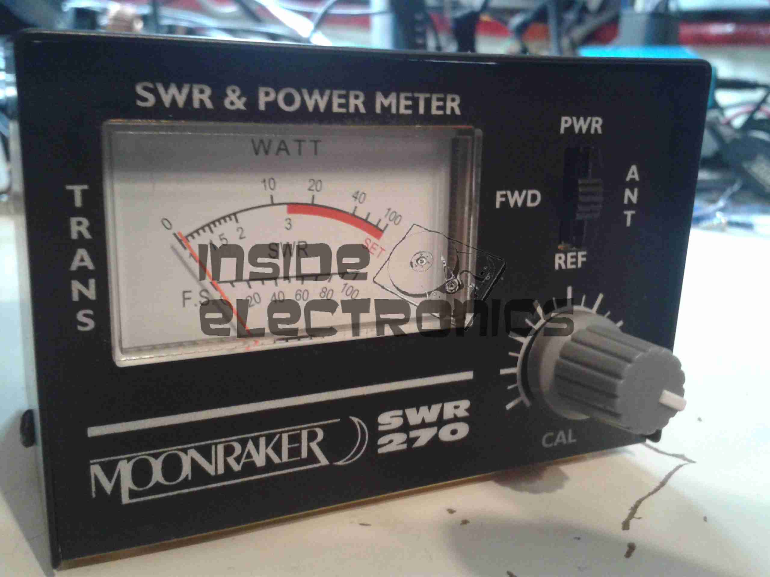
As I’m building up my radio shack, I figured an SWR meter would be a handy addition to my arsenal. This is a cheap Moonraker brand meter, which also will measure RF power. Above the front of the meter is shown, with the moving coil meter movement on the left, calibration adjustment on the right & the forward/reverse power switch.
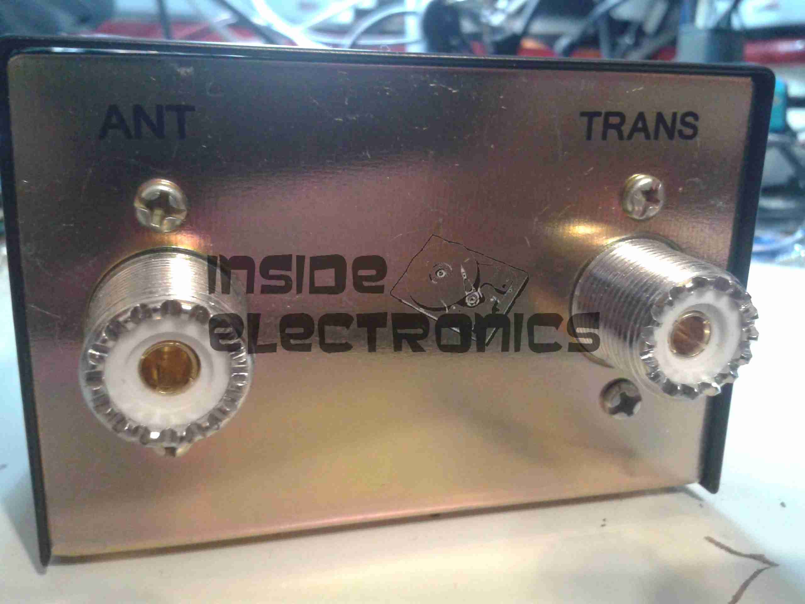
For connections, standard SO-259 jacks are provided. The casing is sturdy 1mm steel. This is good, considering it’ll probably take a beating in my portable radio bag.
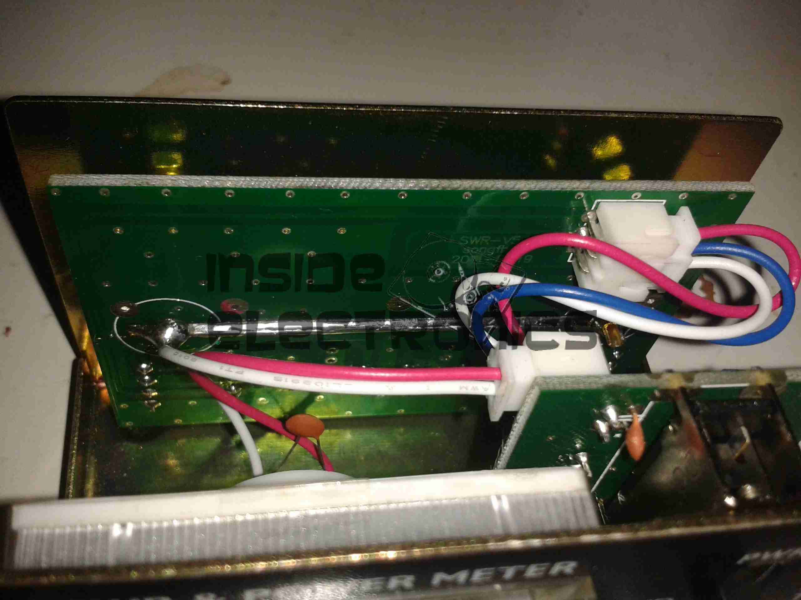
Here the cover is removed, showing some of the internals. The large PCB across the back is the directional coupler.

The SO-259 connectors are bridged with a transmission line, (the track covered in solder in the image below), while there are a pair of sense lines running alongside. This main line is electromagnetically coupled to the two smaller sense lines, which are terminated at one end with resistors, with diodes at the other to rectify the coupled signal.
The termination resistors are sized to match the impedance of the sense lines.
The diodes, having rectified the coupled RF, produce DC voltages representing the value of the forward & reverse RF power. These DC voltages are smoothed with the capacitors.
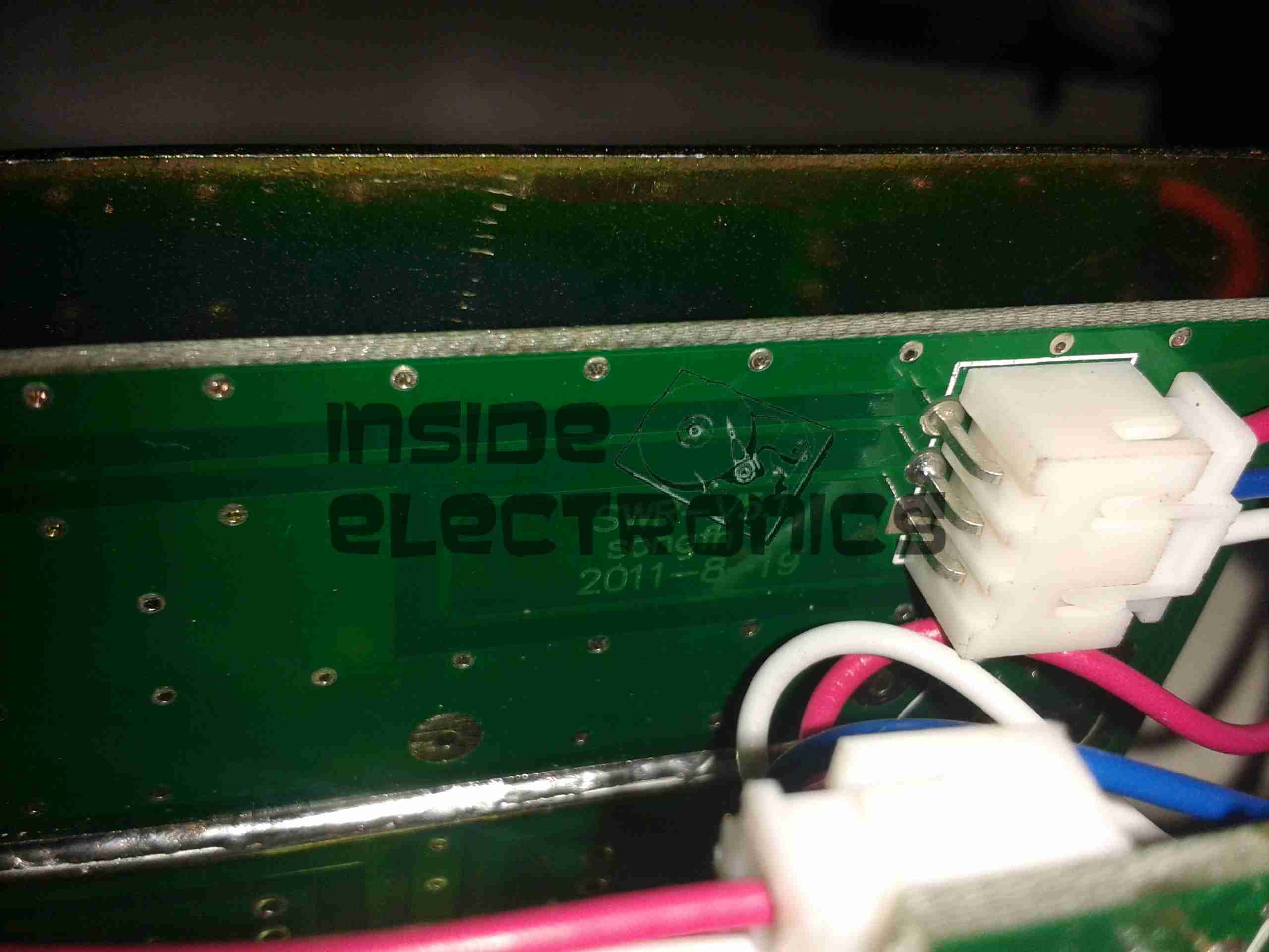
The PCB is dated 19-8-2011, so it’s a fairly old design.
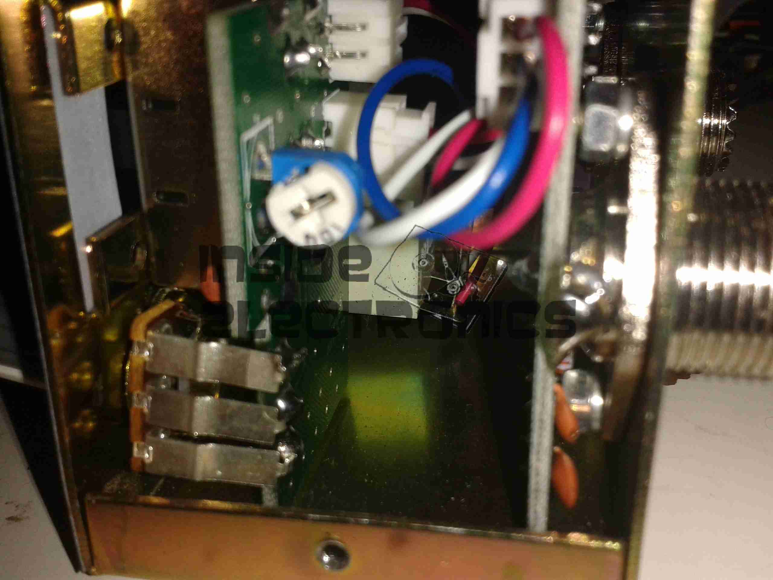
Here is visible the back of the user calibration adjuster, with the factory calibration trimmer.
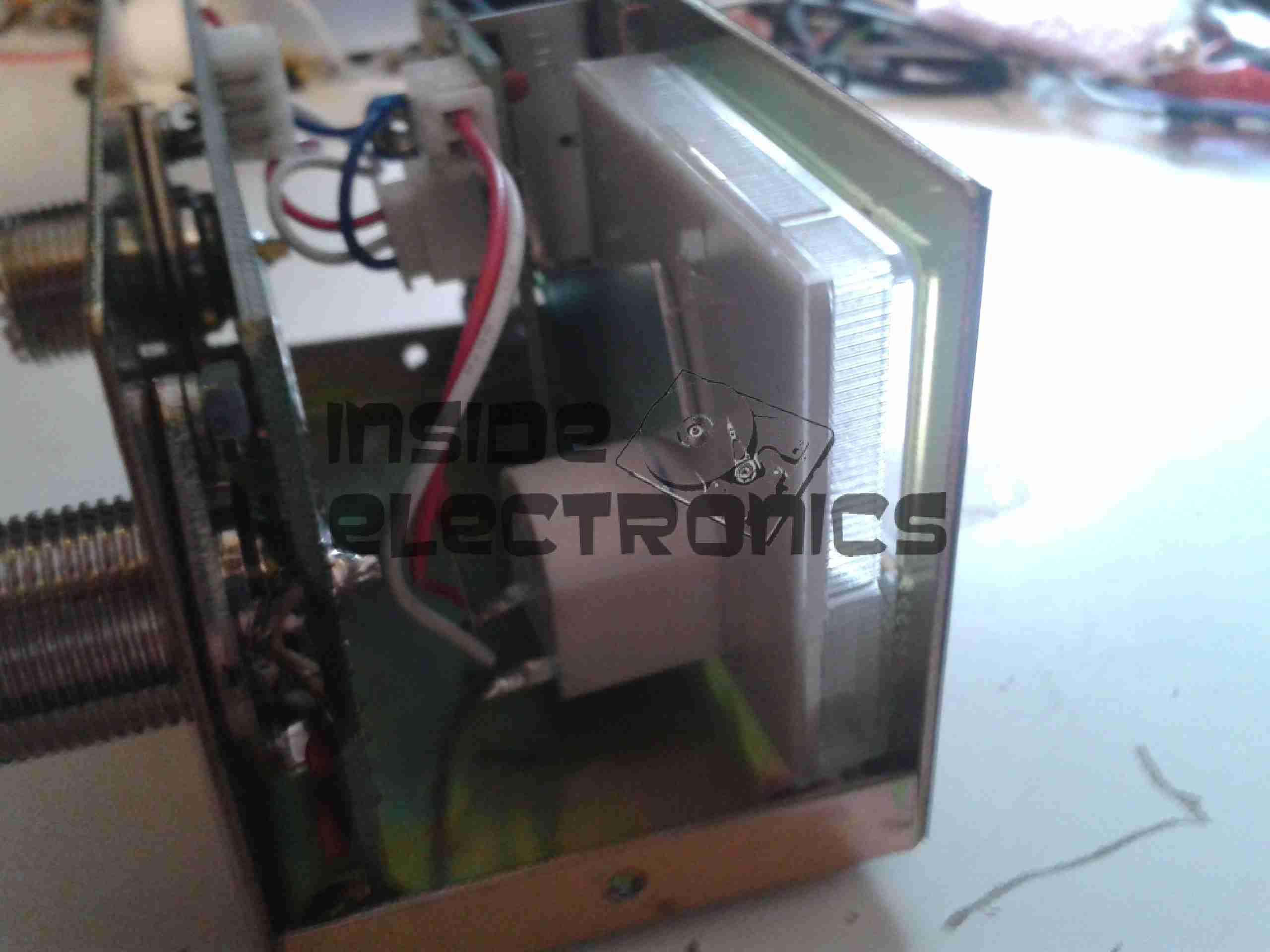
Back of the meter movement. This is a standard moving coil type. Nothing special.
This meter will soon be modified to accept connection of an external Arduino-based SWR & power meter, which I can calibrate individually for each band.
Stay tuned for that upcoming project.
