Posted on Leave a comment

New Radio – Baofeng UV-82

Thanks to Lewis over at Distant Signal Radio, the bad influence he is on my bank balance ;), I’m the proud new owner of a new Baofeng. This time it’s the UV-82.

This radio is a little different from the other Baofengs I have. Here are the main differences:

  • Dual PTT – This one is going to take some getting used to 😉
  • Higher capacity battery pack
  • A more rugged, commercial feel

This radio has a different method of selecting the VFO mode – holding the menu key while the unit is powered on. This is a little awkward, but since I only usually use my local repeaters when I’m mobile, it’s not much of an issue.

UV-82
UV-82

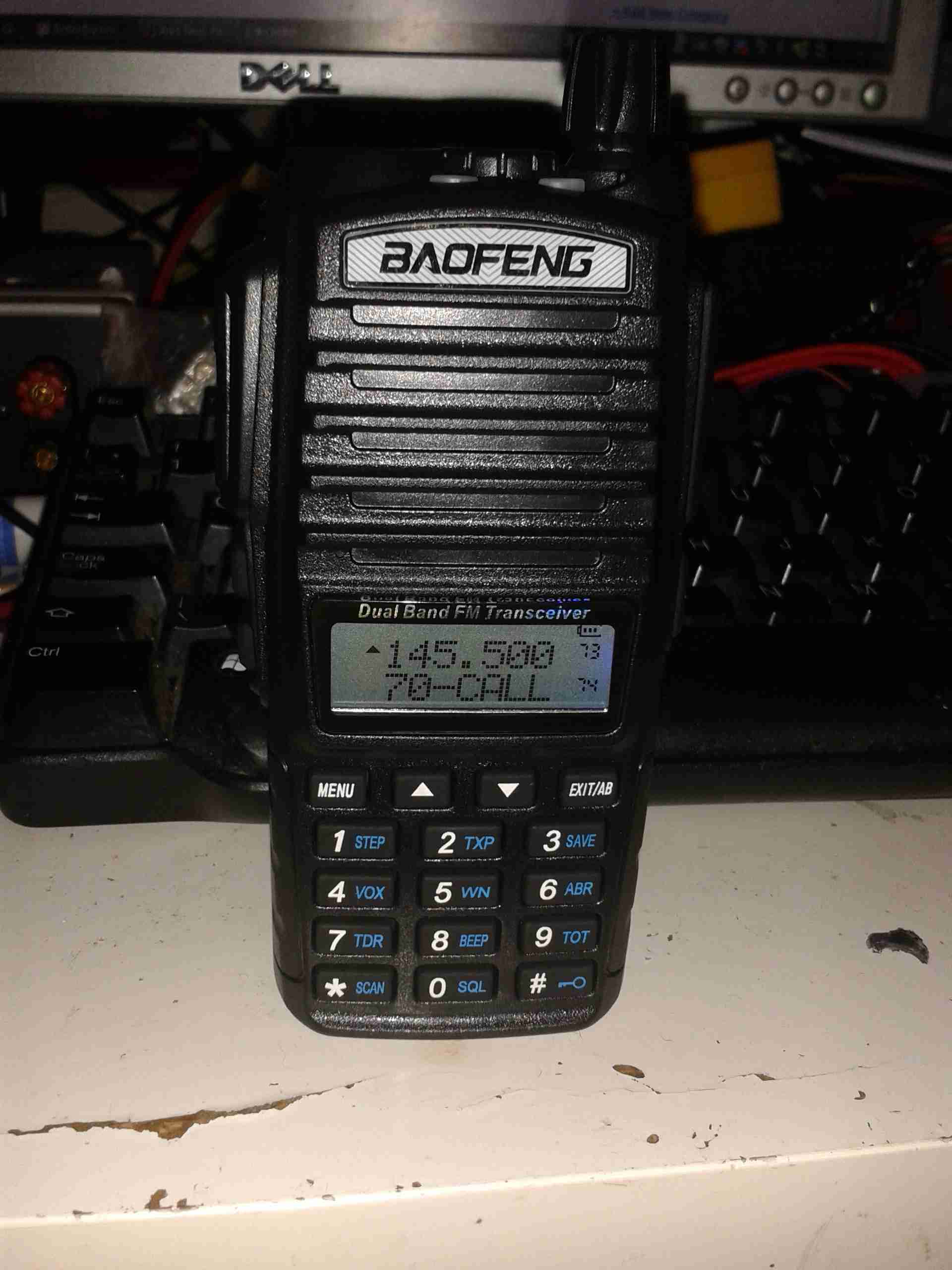
Here’s the radio itself, it has a much more commercial feel to it than the UV-5Rs, and it’s slightly bigger. Mainly due to the use of a larger standard battery & larger loudspeaker.

Spec Label
Spec Label

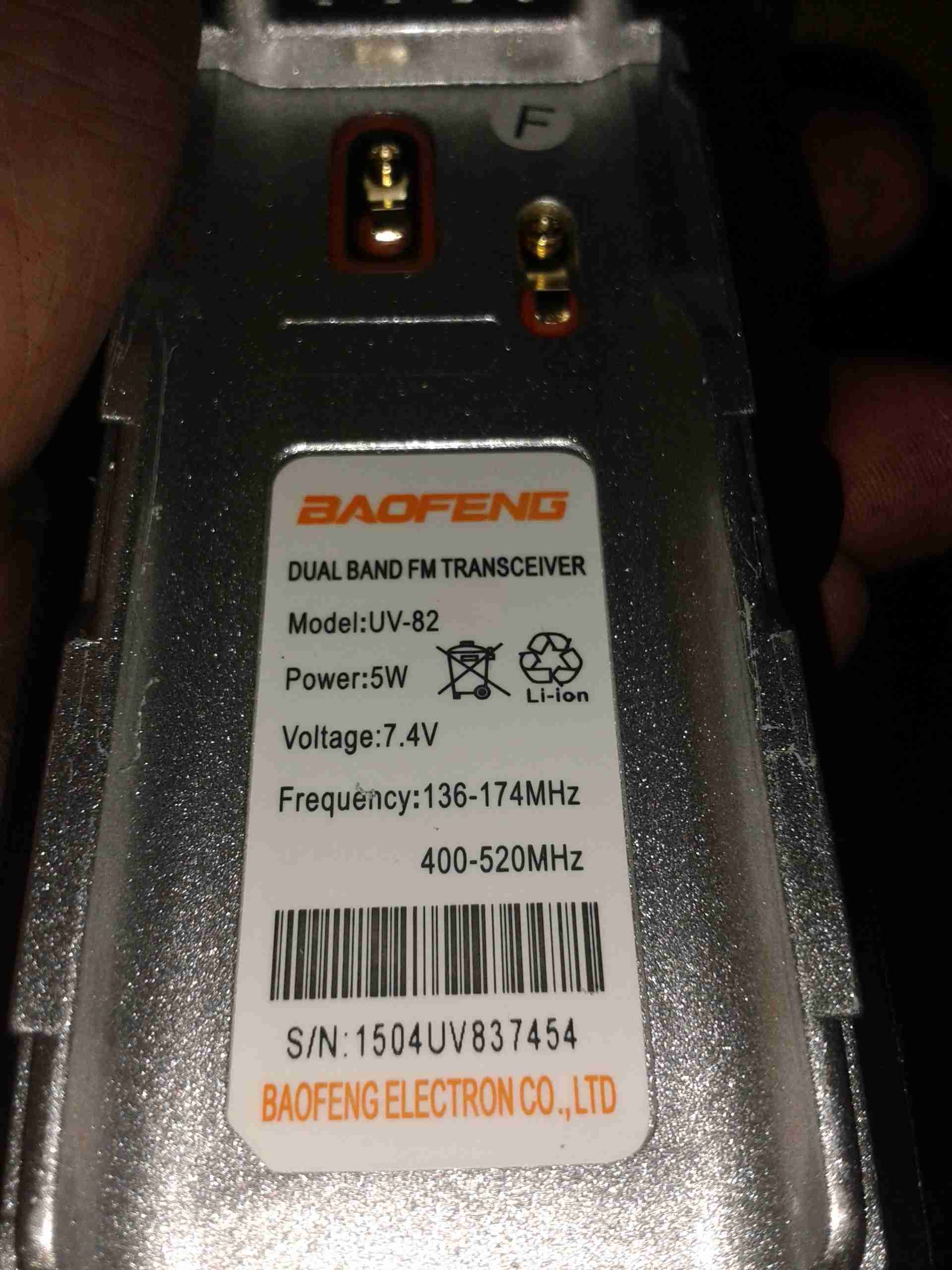
Back of the unit with the spec label. As per usual Baofeng are a bit conservative with the power ratings, more to come on that below.

Battery Pack
Battery Pack

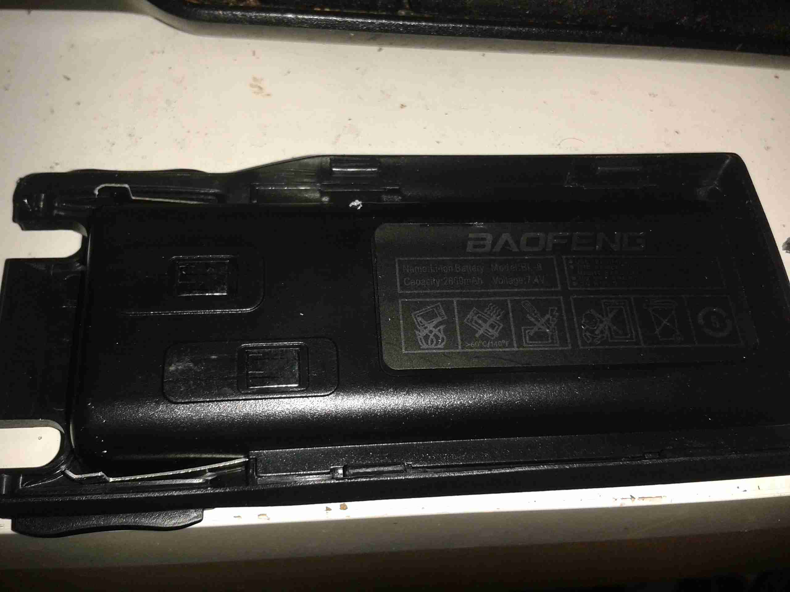
Here’s the battery pack, a 2-cell lithium-polymer unit. This has a bigger capacity than the standard UV-5R battery, at 2800mAh.

Here are the power settings as measured by my GY-561. Frequencies used are 145.500 & 433.500


VHF High: 7W
VHF Low: 2.5W


UHF High: 6W
UHF Low: 3.1W


Posted on Leave a comment

AD9850 VFO Board

Continuing from my previous post where I published an Eagle design layout for AD7C‘s Arduino powered VFO, here is a completed board.

I have made some alterations to the design since posting, which are reflected in the artwork download in that post, mainly due to Eagle having a slight psychotic episode making me ground one of the display control signals!

AD9850 VFO
AD9850 VFO

The amplifier section is unpopulated & bypassed as I was getting some bad distortion effects from that section, some more work is needed there.
The Arduino Pro Mini is situated under the display, and the 5v rail is provided by the LM7805 on the lower left corner.

Current draw at 12v input is 150mA, for a power of 1.8W total. About 1W of this is dissipated in the LM7805 regulator, so I have also done a layout with an LM2574 Switching Regulator.
The SMPS version should draw a lot let power, as less is being dissipated in the power supply, but this version is more complex.

DDS VFO-SMPS
DDS VFO-SMPS

Here the SMPS circuit can be seen on the left hand side of the board, completely replacing the linear regulator.
I have not yet built this design, so I don’t know what kind of effect this will have on the output signal, versus the linear regulator. I have a feeling that the switching frequency of the LM2574 (52kHz) might produce some interference on the output of the DDS module. However I have designed this section to the standards in the datasheet, so this should be minimal.

Nevertheless this version is included in the Downloads section at the bottom of this post.

The output coupled through a 100nF capacitor is very clean, as can be seen below, outputting a 1kHz signal. Oscilloscope scale is 0.5ms/div & 1V/div.

VFO Output
VFO Output (Mucky ‘Scope)
Scope Connected
Scope Connected


Thanks again to Rich over at AD7C for the very useful tool design!

Linked below is the Eagle design files for this project, along with my libraries used to create it.

[download id=”5571″]

[download id=”5573″]

[download id=”5575″]

Posted on 4 Comments

AD9850 DDS VFO PCB & Schematic Layout

I recently came across a design for an Arduino controlled AD9850 DDS module, created by AD7C, so I figured I would release my Eagle CAD design for the PCB here.

It is a mainly single-sided layout, only a few links on the top side are needed so this is easy to etch with the toner transfer method.

My version uses an Arduino Pro Mini, as the modular format is much easier to work with than a bare ATMega 328.

RF output is via a SMA connector & has a built in amplifier to compensate for the low level generated by the DDS Module.

DDS VFO
DDS VFO

Version 2 Update: Added reverse polarity protection, added power indicator LED, beefed up tracks around the DC Jack.
[download id=”5571″]