![Front Front](http://www.experimental-engineering.co.uk/wp-content/uploads/2011/02/03122008255-300x187.jpg)
Here is a cheap no frills microwave oven, which died after a few weeks of normal use.
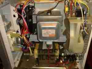
![Electronics Bay Electronics Bay](http://www.experimental-engineering.co.uk/wp-content/uploads/2011/02/03122008257-300x225.jpg)
Cover removed, showing the internals. Front of the microwave is on the left.
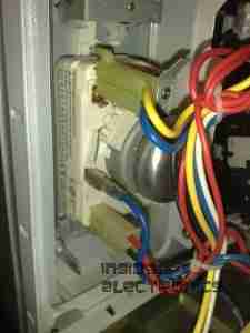
![Timer Timer](http://www.experimental-engineering.co.uk/wp-content/uploads/2011/02/03122008260-225x300.jpg)
Closeup of the timer unit. Cheap & nasty.
![Magnetron Magnetron](http://www.experimental-engineering.co.uk/wp-content/uploads/2011/02/03122008262-300x225.jpg)
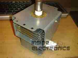
Magnetron removed from the oven. Antenna is on the top, cooling fins visible in the center. White conector at the bottom is the filament terminals.
![Magnetron Chokes Magnetron Chokes](http://www.experimental-engineering.co.uk/wp-content/uploads/2011/02/03122008271-300x225.jpg)
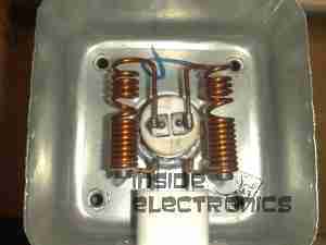
Chokes on the magnetron’s filament connections. These prevent microwave energy from feeding back into the electronics bay through the connections.
![Magnetron Assembly Magnetron Assembly](http://www.experimental-engineering.co.uk/wp-content/uploads/2011/02/03122008272-300x225.jpg)
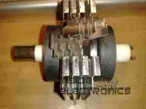
Magnetron cooling fins, tube & magnets removed from the frame.
![Magnetron Tube Magnetron Tube](http://www.experimental-engineering.co.uk/wp-content/uploads/2011/02/03122008273-300x225.jpg)
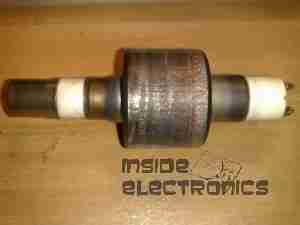
Bare magnetron tube.
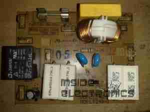
![Power Input Board Power Input Board](http://www.experimental-engineering.co.uk/wp-content/uploads/2011/02/03122008263-300x225.jpg)
This PCB does some rudimentary power conditioning, power resistors are in series with the live feed to the power trasformer, to prevent huge power up surge. When the transformer energizes the relay, which is in parallel with the resistors, switches them out a fraction of a second after, providing full power to the transformer.
Standard RFI choke & capacitor at the top of the board, with the input resistor.
![Transformer Transformer](http://www.experimental-engineering.co.uk/wp-content/uploads/2011/02/03122008266-300x225.jpg)
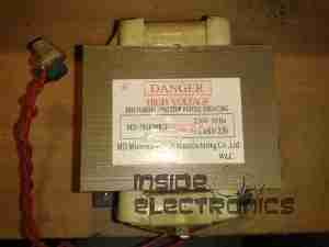
Power transformer to supply the magnetron with high voltage.
Power output is ~2kV at ~0.5A. Pair of spade terminals are the low voltage filament winding.
![Capacitor Capacitor](http://www.experimental-engineering.co.uk/wp-content/uploads/2011/02/03122008265-300x225.jpg)
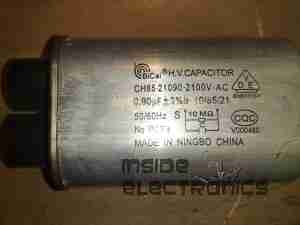
HV Capacitor. This along with the diode form a voltage doubler, to provide the magnetron with ~4kV DC.

![Diode Diode](http://www.experimental-engineering.co.uk/wp-content/uploads/2011/02/03122008264-300x225.jpg)
HV diode stack.
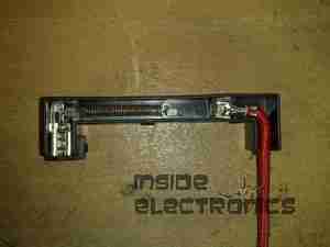
![Fuse Element Fuse Element](http://www.experimental-engineering.co.uk/wp-content/uploads/2011/02/03122008267-300x225.jpg)
Internals of the HV fuse. Rated for ~0.75A at 5kV. The fuse element is barely visible attached to the end of the spring. Connects between the transformer & the capacitor.

![Cooling Fan Cooling Fan](http://www.experimental-engineering.co.uk/wp-content/uploads/2011/02/03122008269-300x225.jpg)
Cooling fan for the magnetron. Drive is cheap shaded pole motor.
![Fan Motor Fan Motor](http://www.experimental-engineering.co.uk/wp-content/uploads/2011/02/03122008270-225x300.jpg)
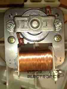
Fan motor. Basic 240v shaded pole induction type.