Posted on 2 Comments

Fire Angel CO-9D Carbon Monoxide Detector Teardown

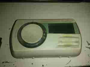
Fire Angel CO-9D CO Detector

This detector has now been retired from service since it’s a fair bit out of date. So here’s the teardown!
Information
Information

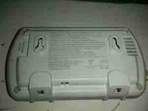
Unlike older detectors, this unit has a built in battery that never needs replacing during the life of the sensor, so once the unit reaches it’s expiry date it’s just trashed as a whole.
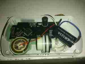
Cover Removed
Cover Removed

4 screws hold the cover on, here’s the internals of the detector. There’s a 3v CR123A LiMnO² cell at the right for power, rated at 1500mAh. A 7 year life is quite remarkable on a single cell!
The sensor is just to the left of the lithium cell, and is of quite unusual construction. Previous CO sensor cells I’ve seen have been small cylinders with a pair of brass pins. This one appears to use a conductive plastic as the connections. These sensors contain H²SO⁴ so they’re a bit hazardous to open.
There are no manufacturer markings on the sensor & I’ve not been able to find any similarly shaped devices, so I’m unsure of it’s specifications.
The alarm sounder is on the left, the usual Piezo disc with a resonator to increase the loudness.
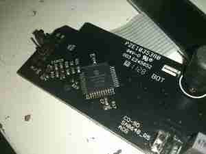
Microcontroller
Microcontroller

The brains of the device are provided by a Microchip PIC16F914 microcontroller. This is a fairly advanced device, with many onboard features, and NanoWatt™ technology, standby power consumption is <100nA according to Microchip’s Datasheet. This would explain the incredible battery life.
The choke just at the right edge of the photo is actually a transformer to drive the Piezo sounder at high voltage.
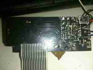
PCB Reverse
PCB Reverse

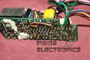
Here’s the PCB with the LCD frame removed. Not much to see on the this side, the silence/test button top right & the front end for the sensor.
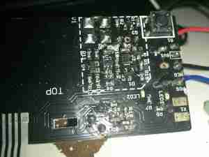
Sensor Front End Amplifier

Here’s a closer look at the front end for the CO sensor cell itself. I haven’t been able to decode the SMT markings on the SOT packages, but I’m guessing that there’s a pair of OpAmps & a voltage reference.
Posted on 2 Comments

Active Ultracapacitor Balancing

Here’s another active balancing circuit for large ultracapacitor banks, this one is designed for a series string of 6, at 2.5v per capacitor.

Based on the design here, I have transcribed the circuit into Eagle & designed a PCB layout.

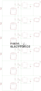
Ultracap Balancer Circuit
Ultracap Balancer Circuit – Click to Embiggen

As can be seen from the circuit diagram above, this is just 6 copies of the circuit from the above link, with screw terminals to attach to the capacitor string.

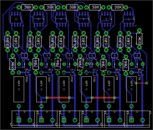
Ultracap Balancer PCB

And here’s the PCB. the MOSFETs & OpAmps are very small SMT parts, so require a steady hand in soldering. This board can easily be etched by hand as there’s only 3 links on the top side. No need for a double sided PCB.

As always, the Eagle project files & my Eagle library collection are available below:


Posted on 10 Comments

Camcorder CRT Viewfinder

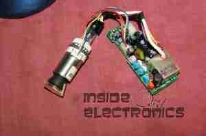
CRT Assembly
CRT Assembly

Here are the viewfinder electronics from a 1984 Hitachi VHS Movie VM-1200E Camcorder. These small CRT based displays accept composite video as input, plus 5-12v DC for power.

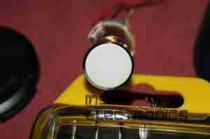
Screen
Screen

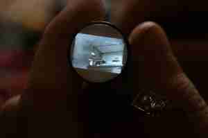
Here is the front face of the CRT, diameter is 0.5″.

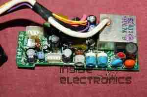
Power Board
Power Board

Closeup view of the PCB, there are several adjustments & a pair of connectors. Socket in the upper left corner is the power/video input. Pinout is as follows:

  1. Brown – GND
  2. Red – Video Input
  3. Orange – +12v DC
  4. Yellow – Record LED
The potentiometers on the PCB from left:
  1. H. ADJ
  2. V. ADJ
  3. BRIGHT
  4. FOCUS
PCB Part Number reads: EM6-PCB
This unit utilises the BA7125L deflection IC.
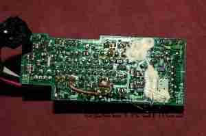
Solderside
Solderside
Reverse side of the PCB, very few SMT components on this board.
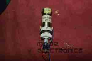
Tube Assembly
Tube Assembly
Here is an overall view of the CRT assembly with scan coils. Tube model is NEC C1M52P45.
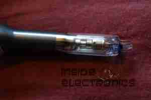
Electron Gun
Electron Gun

Closeup view of the CRT neck, showing the electron gun assembly.


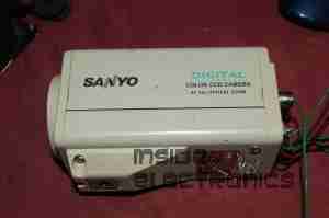
CCTV Camera
CCTV Camera

The old CCTV camera used to feed a composite signal to the CRT board. Sanyo VCC-ZM300P.

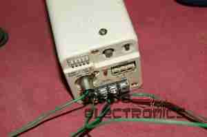
CCTV Camera Connections

Connections at the back of the camera. Red & Black pair of wires lead to 12v power supply, Green & Black pair lead to the CRT board’s power pins. Seperate green wire is pushed into the BNC video connector for the video feed. video ground is provided by the PSU’s ground connection.

Connections
Connections

Finally the connections at the CRT drive board, left to right, +12v, Video, GND.

Screen Operation
Screen Operation

Display taking video signal from the CCTV camera.