Posted on 2 Comments

Active Ultracapacitor Balancing

Here’s another active balancing circuit for large ultracapacitor banks, this one is designed for a series string of 6, at 2.5v per capacitor.

Based on the design here, I have transcribed the circuit into Eagle & designed a PCB layout.

Ultracap Balancer Circuit
Ultracap Balancer Circuit – Click to Embiggen

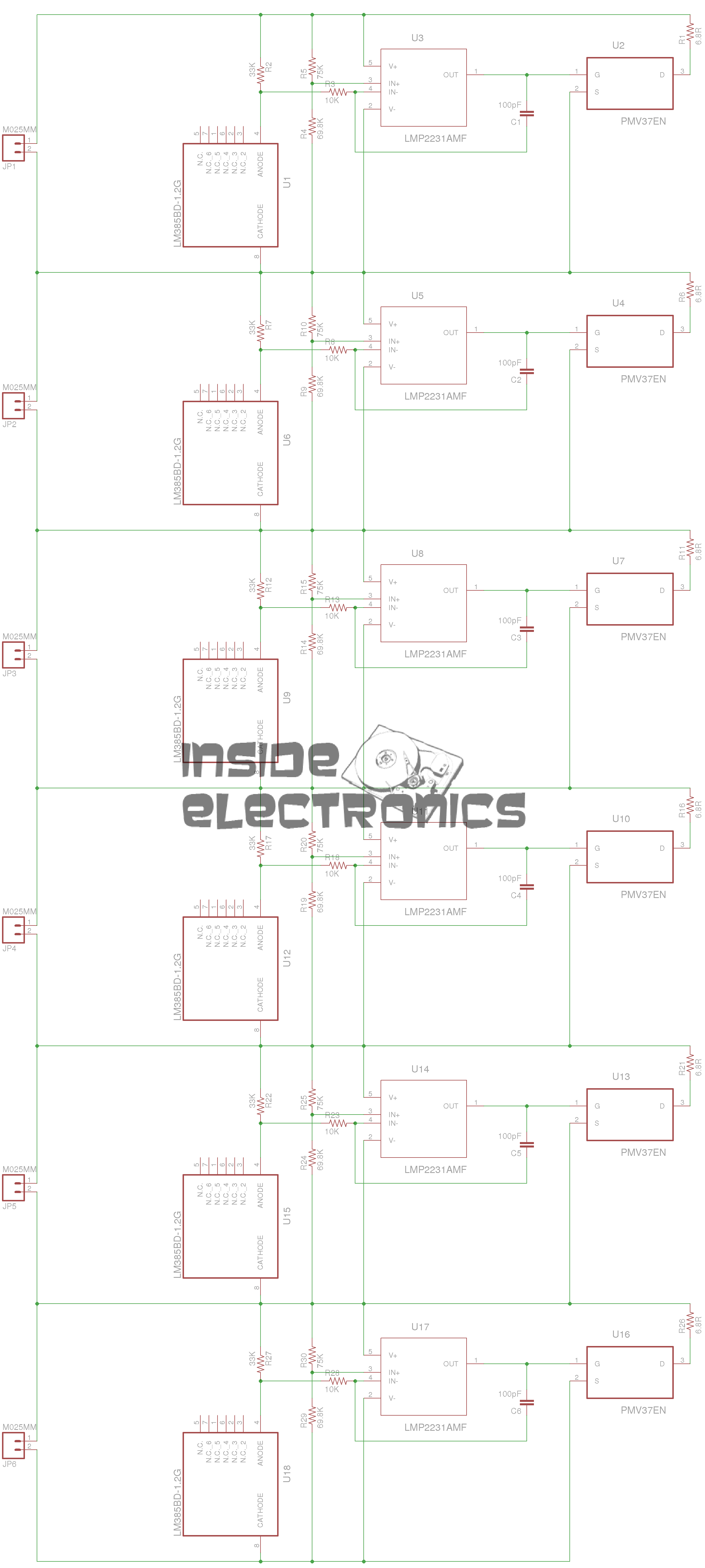
As can be seen from the circuit diagram above, this is just 6 copies of the circuit from the above link, with screw terminals to attach to the capacitor string.

Ultracap Balancer PCB

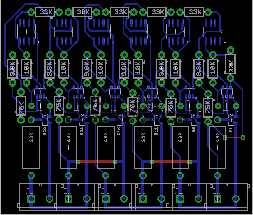
And here’s the PCB. the MOSFETs & OpAmps are very small SMT parts, so require a steady hand in soldering. This board can easily be etched by hand as there’s only 3 links on the top side. No need for a double sided PCB.

As always, the Eagle project files & my Eagle library collection are available below:


Posted on Leave a comment

Ultracapacitor Charge Balancing

Balancer
Balancer

I have finally  got round to designing the balancing circuitry for my ultracapacitor banks, which have a total voltage of 15v when fully charged. The 2600F capacitors have a max working voltage of 2.5v each, so to ensure reliable operation, balancing is required to make sure that each capacitor is charged fully.

The circuit above is a simple shunt regulator, which uses a 2.2v zener diode to regulate the voltage across the capacitor.

A 10W 1Ω resistor is connected to the BALLAST header, while the capacitor is connected across the INPUT. Once the voltage on the capacitor reaches 2.6v, the MOSFET begins to conduct, the 1Ω resistor limiting current to ~2.6A.

Each capacitor in the series string requires one of these connected across it.

PCB
PCB

Below is a link to the Eagle project archive for this. Includes schematic, board & gerber files.

[download id=”5555″]