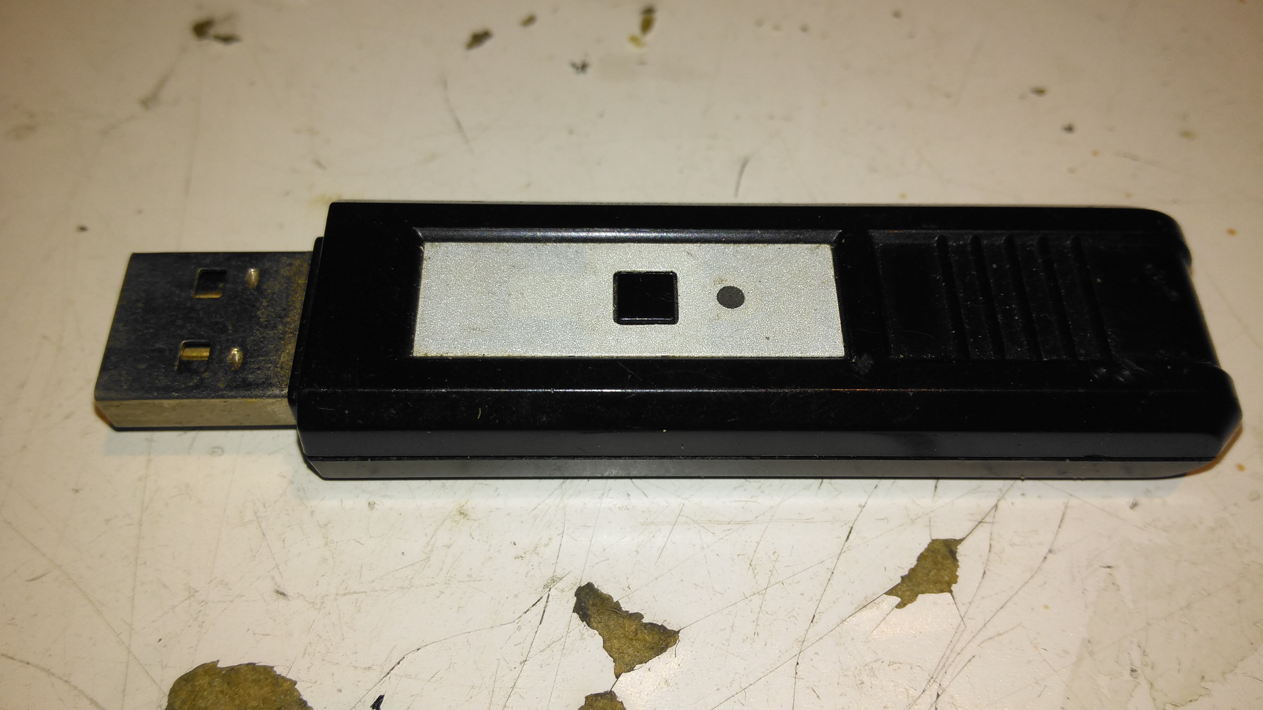
This is a pair of modules that Maplin was selling some time back, to send stereo audio over a 2.4GHz radio link. The transmitter identifies as a USB sound card, I’ve personally used these units to transmit audio about 60ft. The transmitter, above, has a single button for pairing with the receiver below.
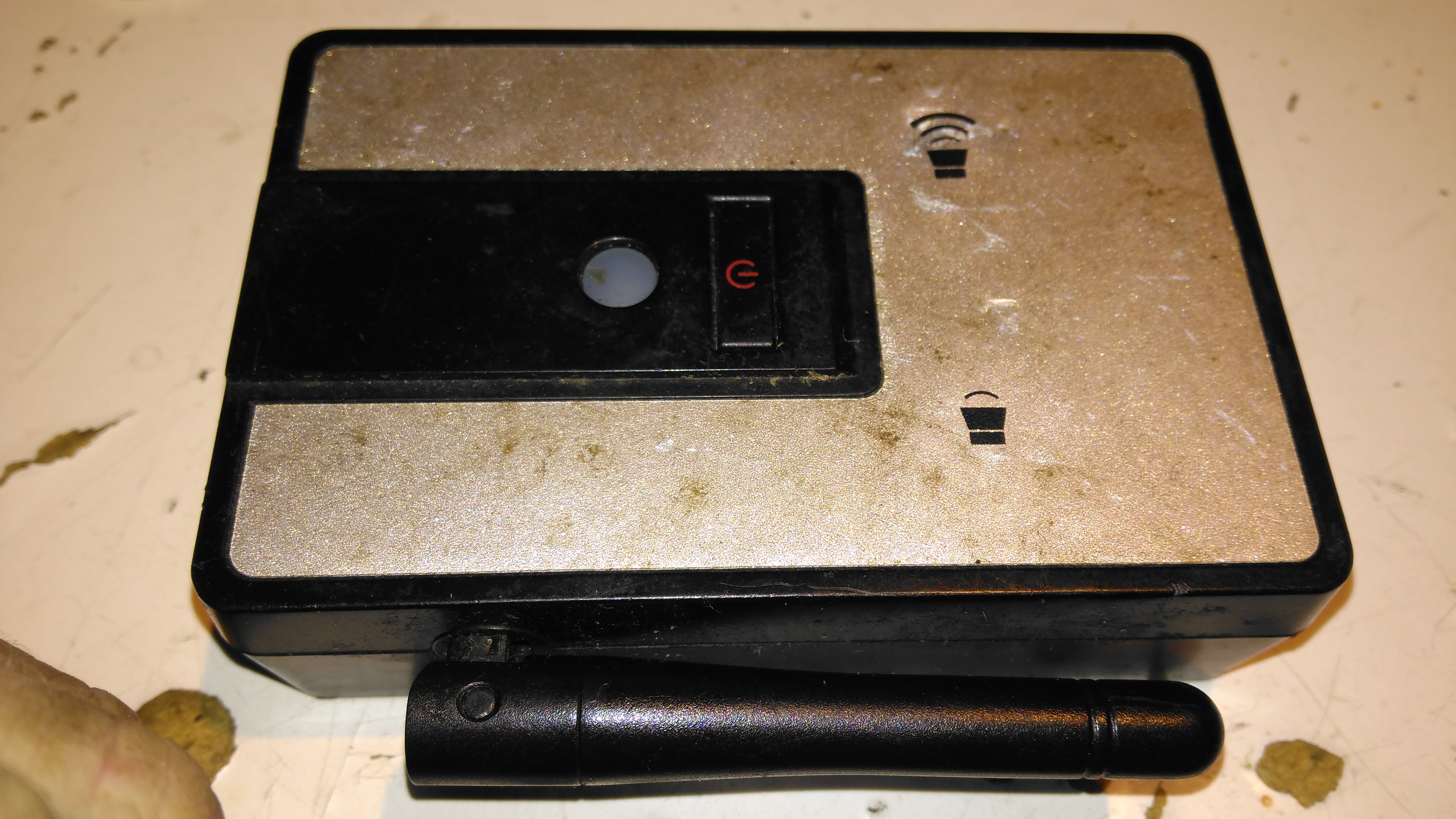
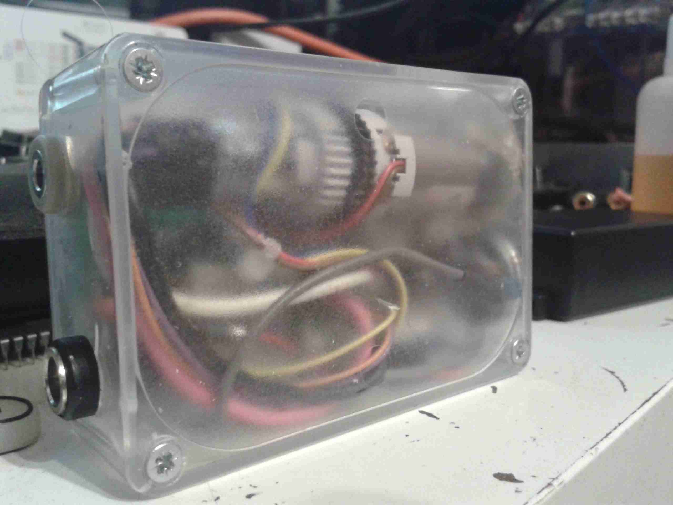
Receiver
The receiver unit has a large external antenna, a link status LED & volume buttons, these directly control the volume level on the host PC via the sound card drivers.
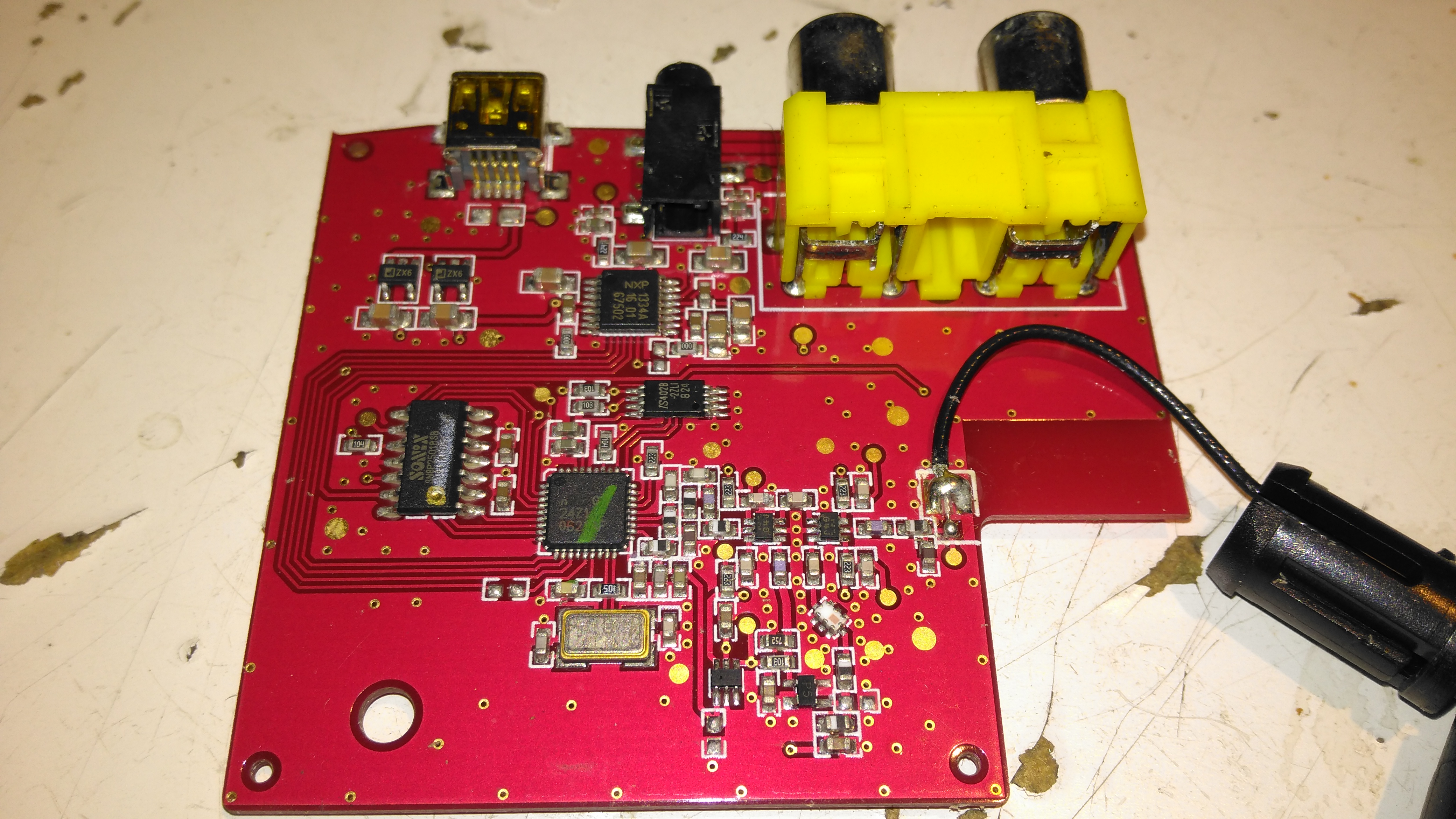
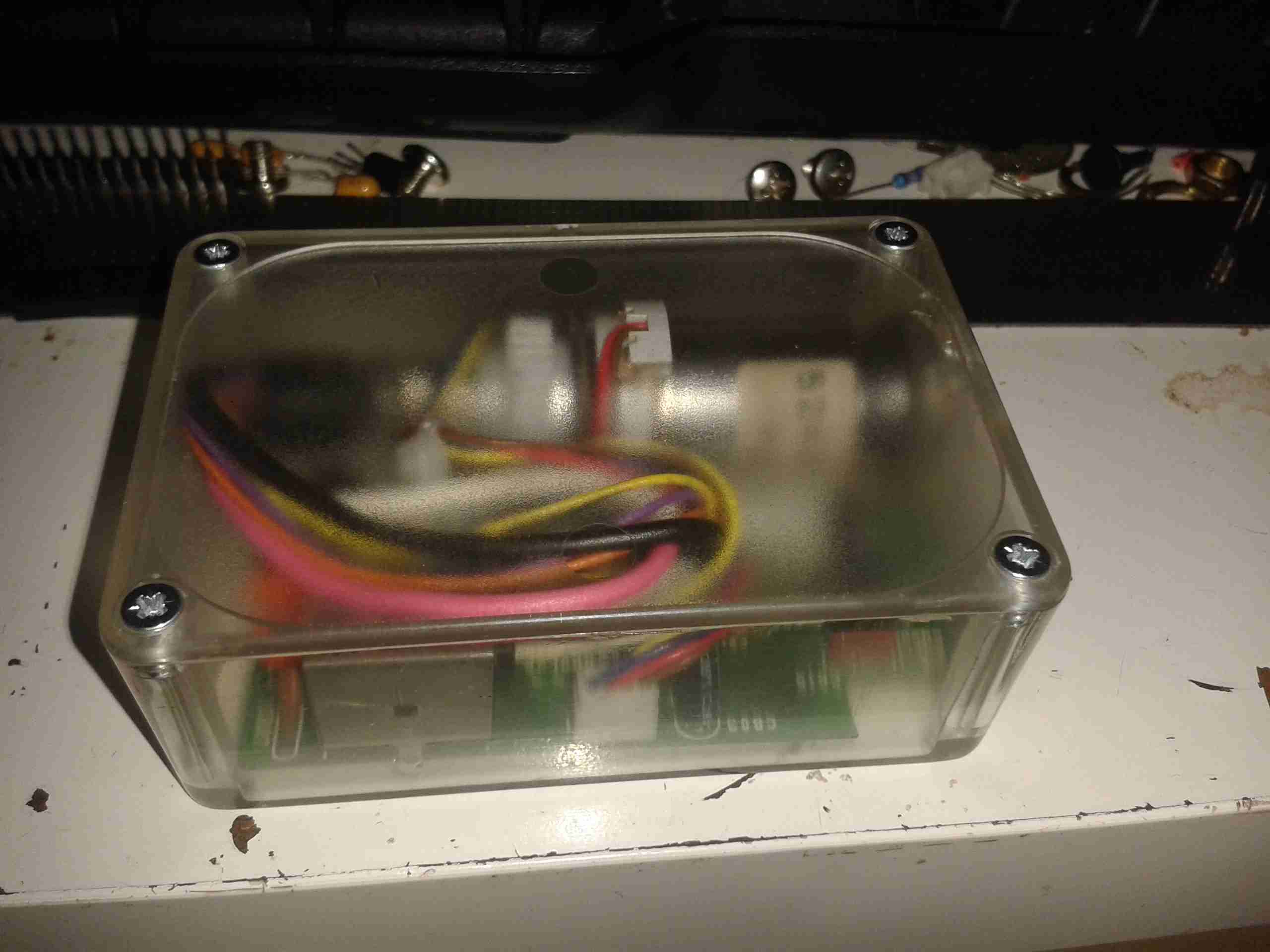
Receiver PCB Top
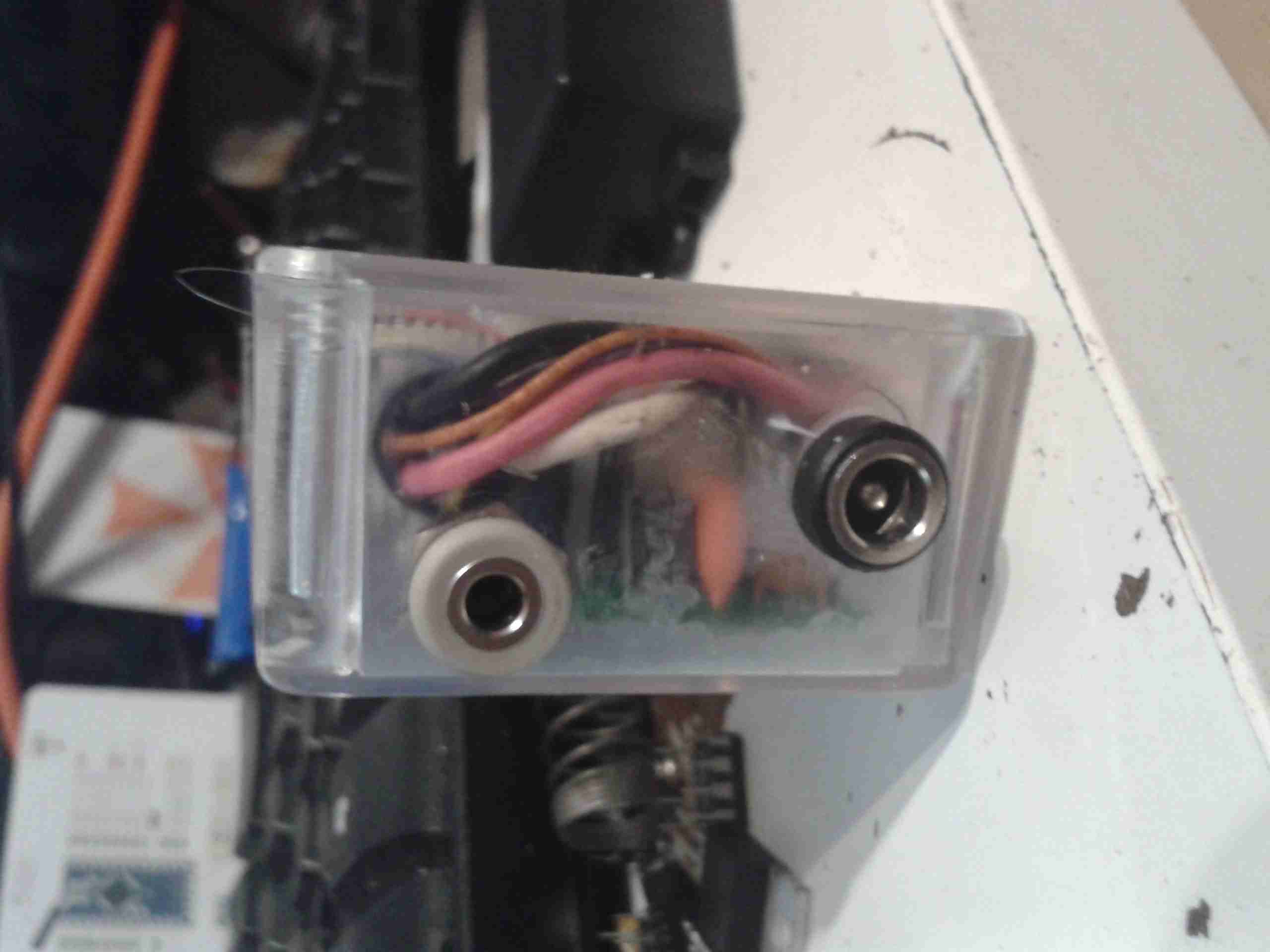
Popping the case open on the receiver reveals a large PCB, holding the chipset, along with the audio output jacks & Mini-USB power input. The antenna Coax is soldered to the PCB.
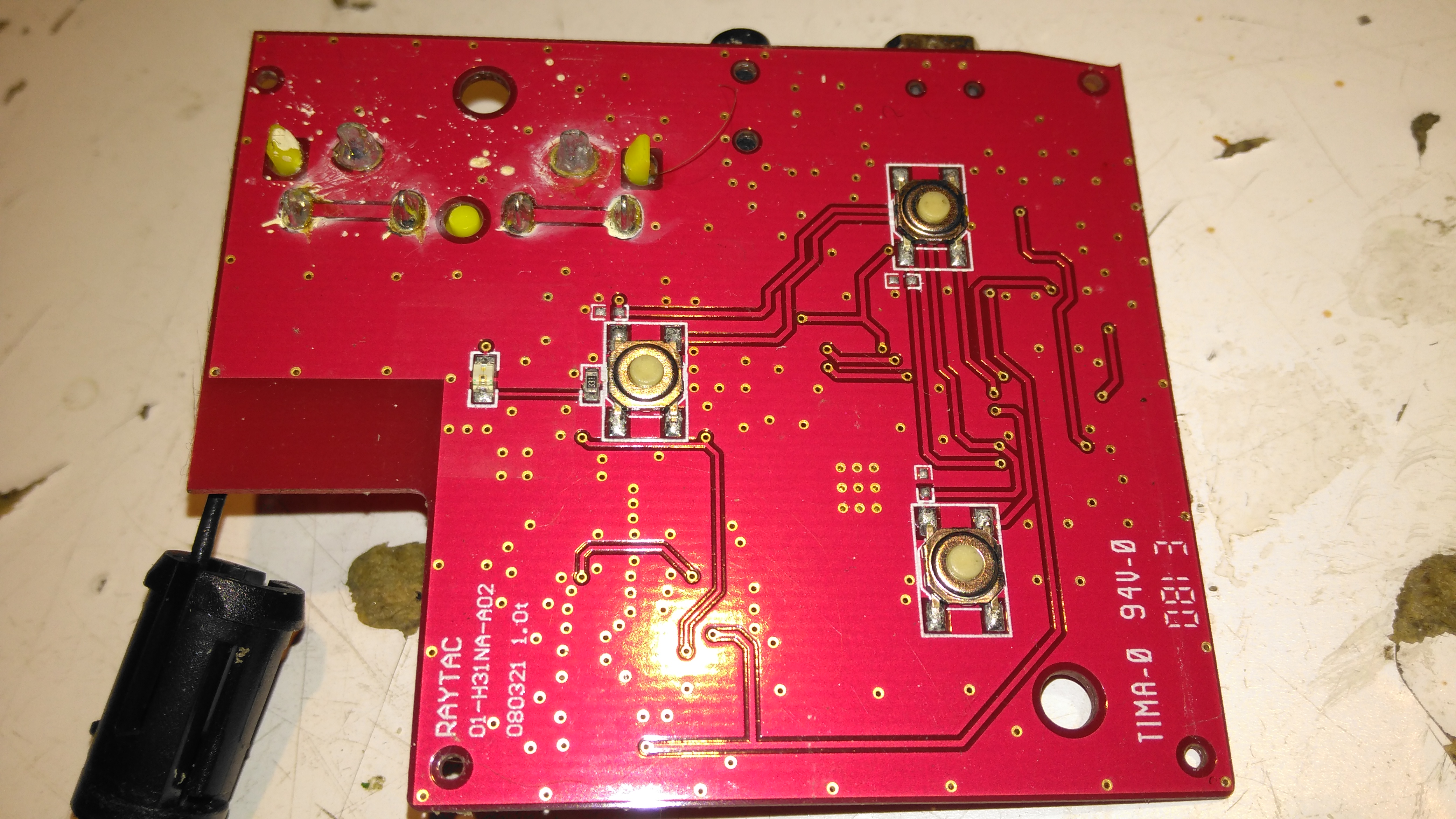
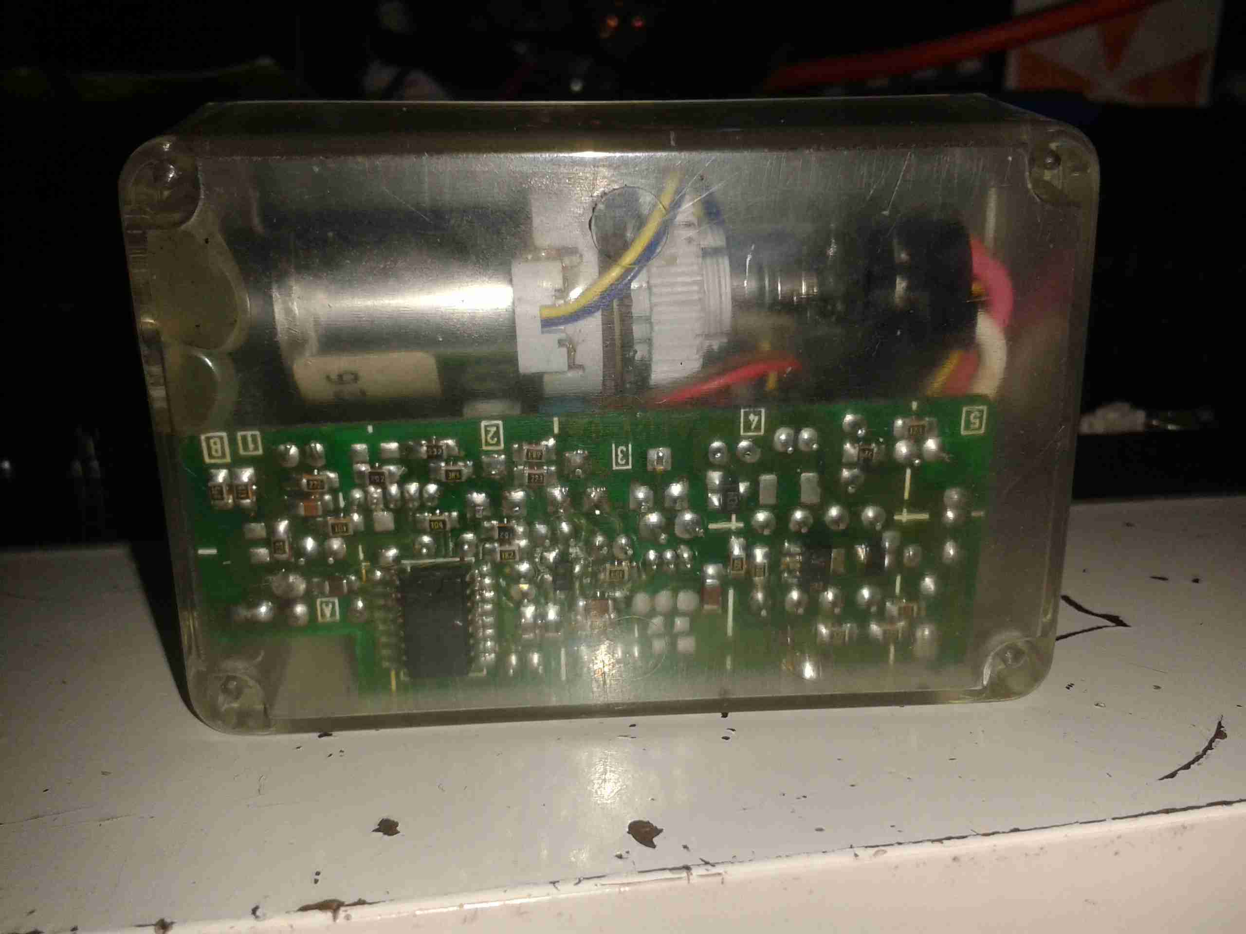
Receiver PCB Bottom
The top of the board has the control buttons, and the status LED.
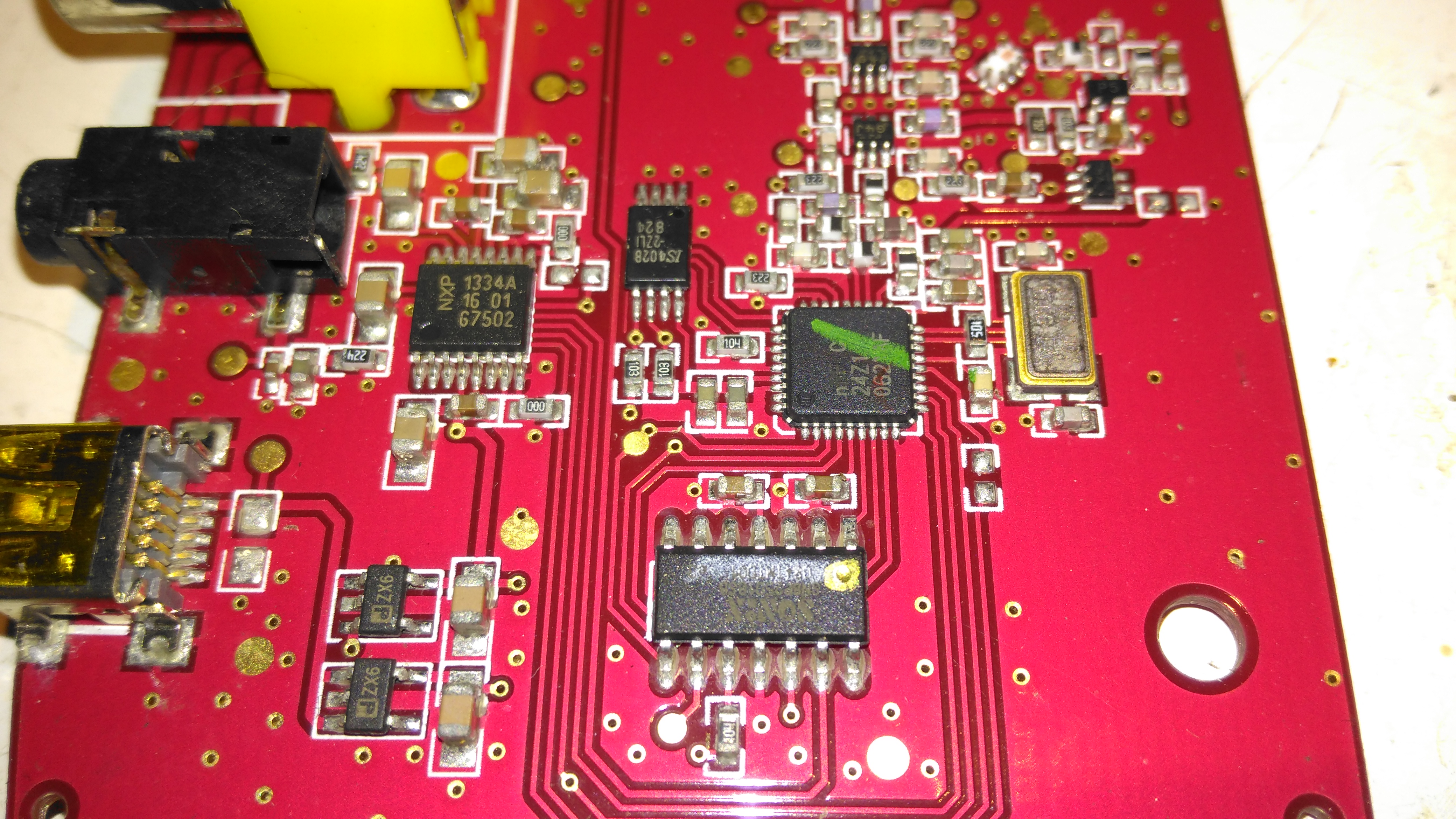
Receiver Chipset
The chipset used here is a Nordic Semiconductor nRF20Z01 2.4GHz Stereo Audio Streamer, there’s a small microcontroller which does all the register magic on the RF transceiver. The RF chain is at the top of the photo, audio outputs on the top left, and the micro USB power input & voltage regulators at bottom left.
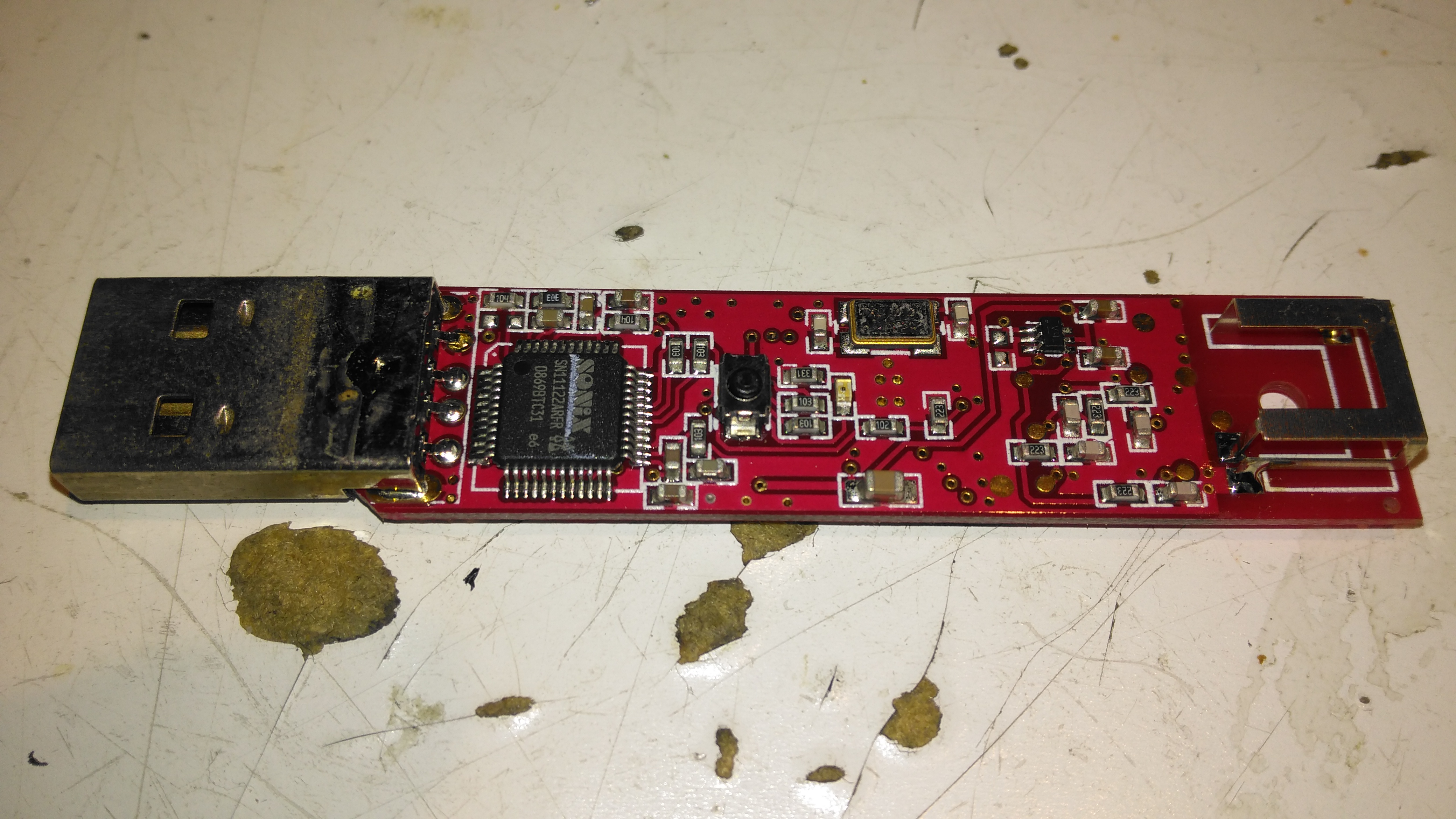
Transmitter PCB Top
The transmitter PCB has a Sonix USB Audio Codec, to interface with the host PC. This is then fed into another Nordic Semi part on the opposite side of the board:
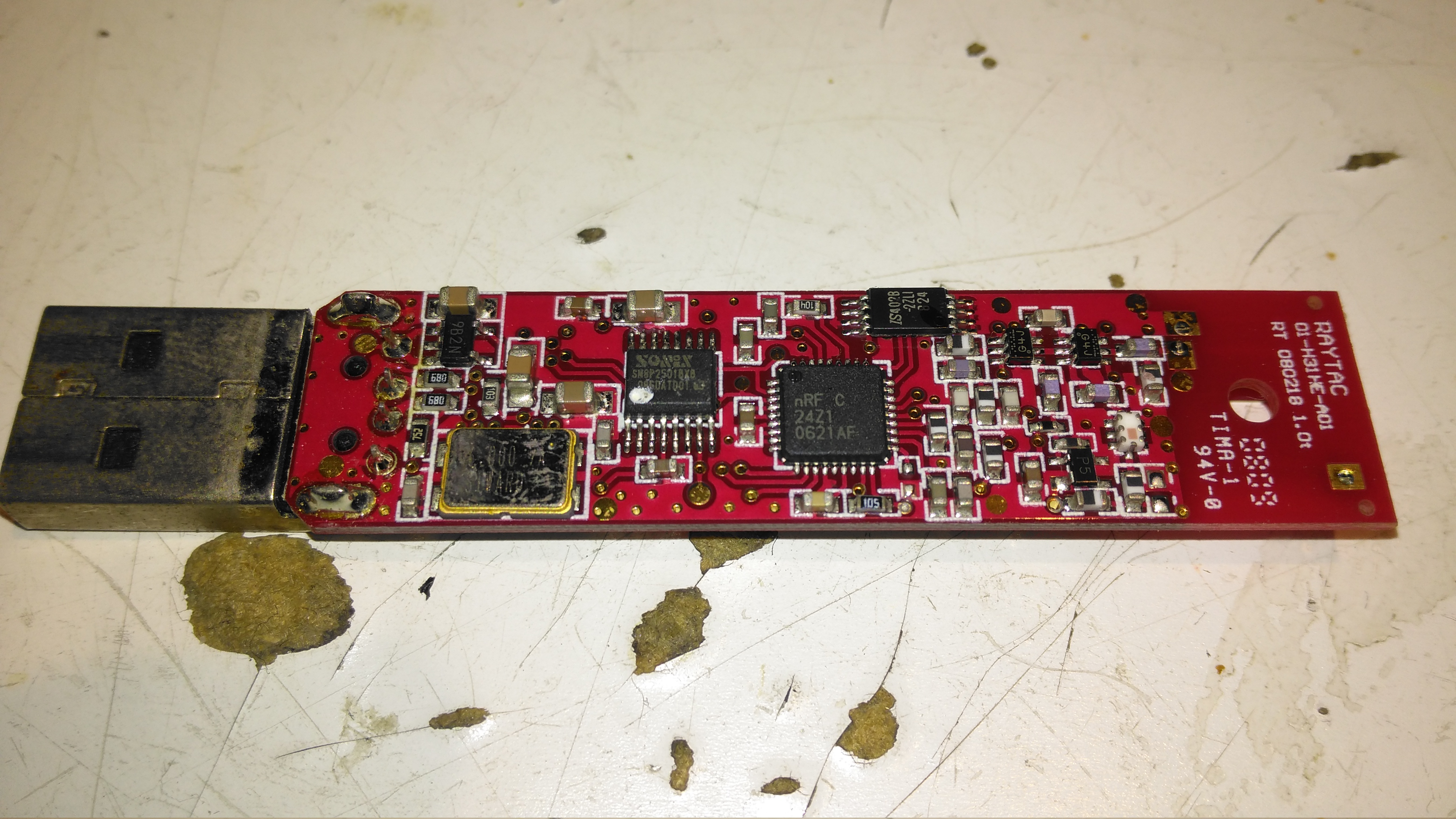
Transmitter PCB Bottom
The bottom of the transmitter has the RF section, and another small control microcontroller.
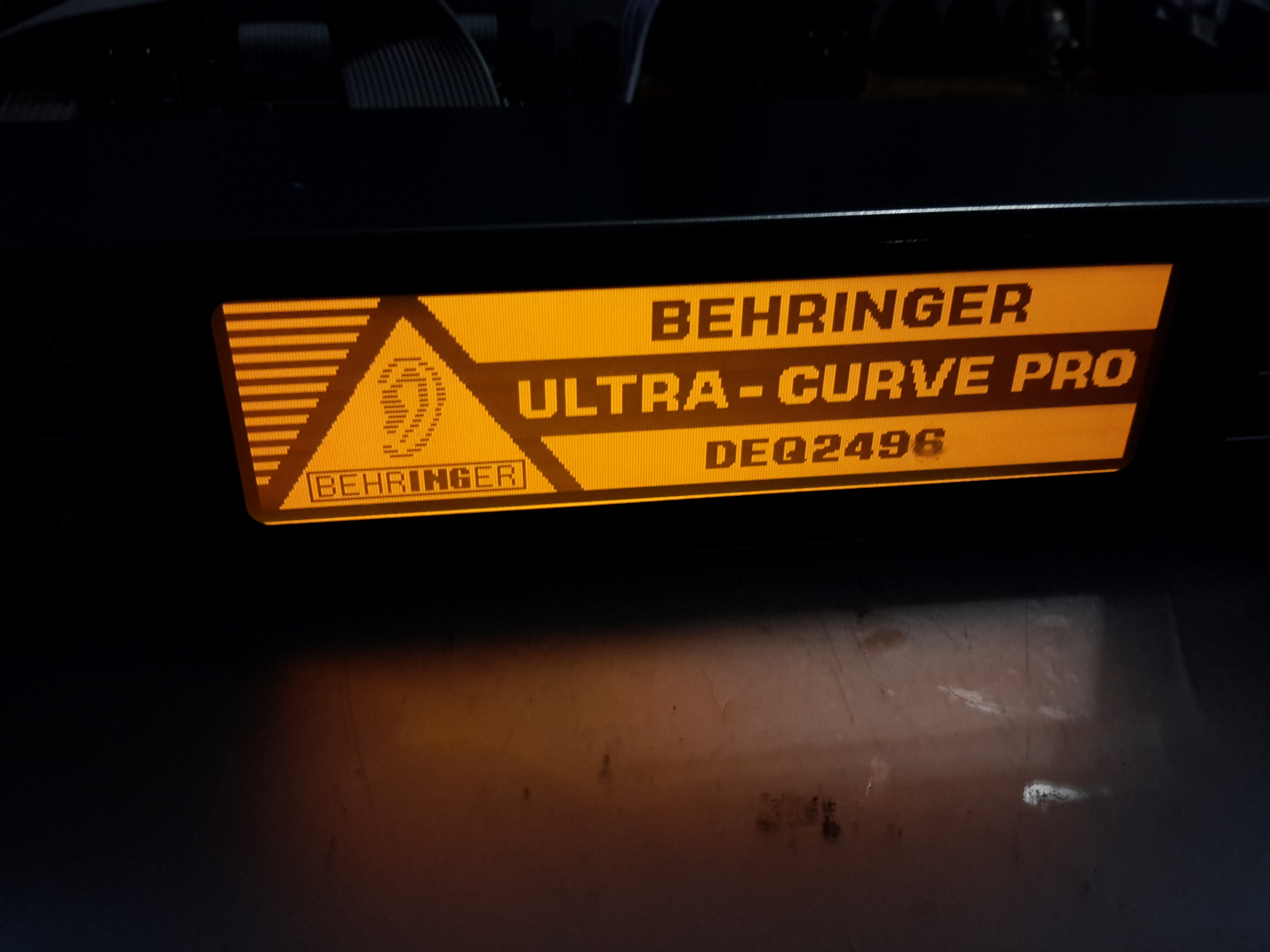
I was recently given this unit, along with another Behringer sound processor to repair, as the units were both displaying booting problems. This first one is a rather swish Mastering Processor, which has many features I’ll leave to Behringer to explain 😉
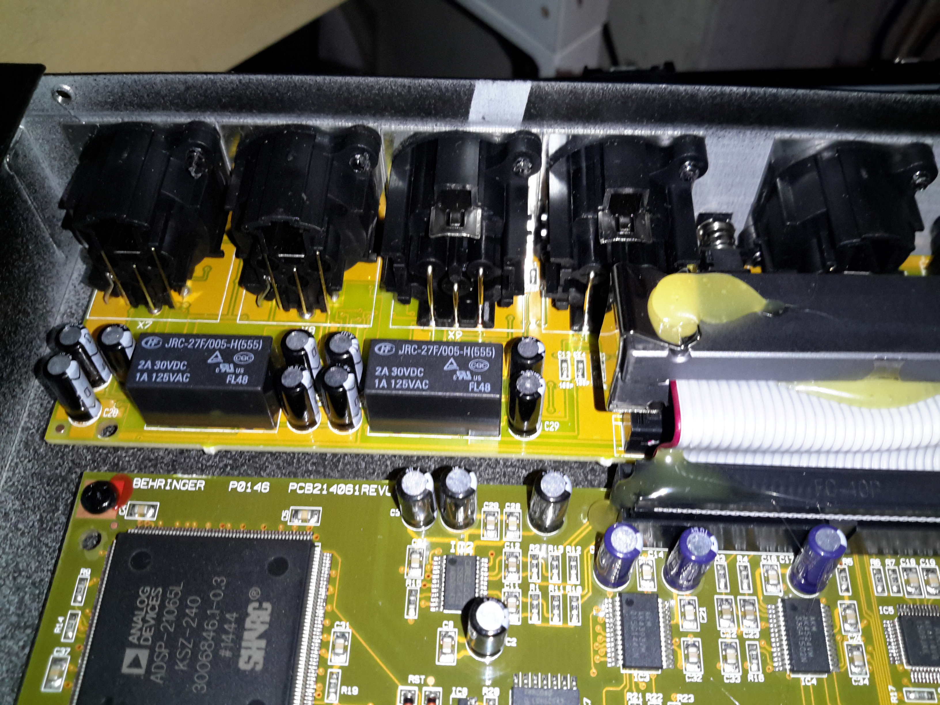
Input Board & Relays
All the inputs are on the back of this 19″ rackmount bit of kit, nothing much on this PCB other than the connectors & a couple of switching relays.
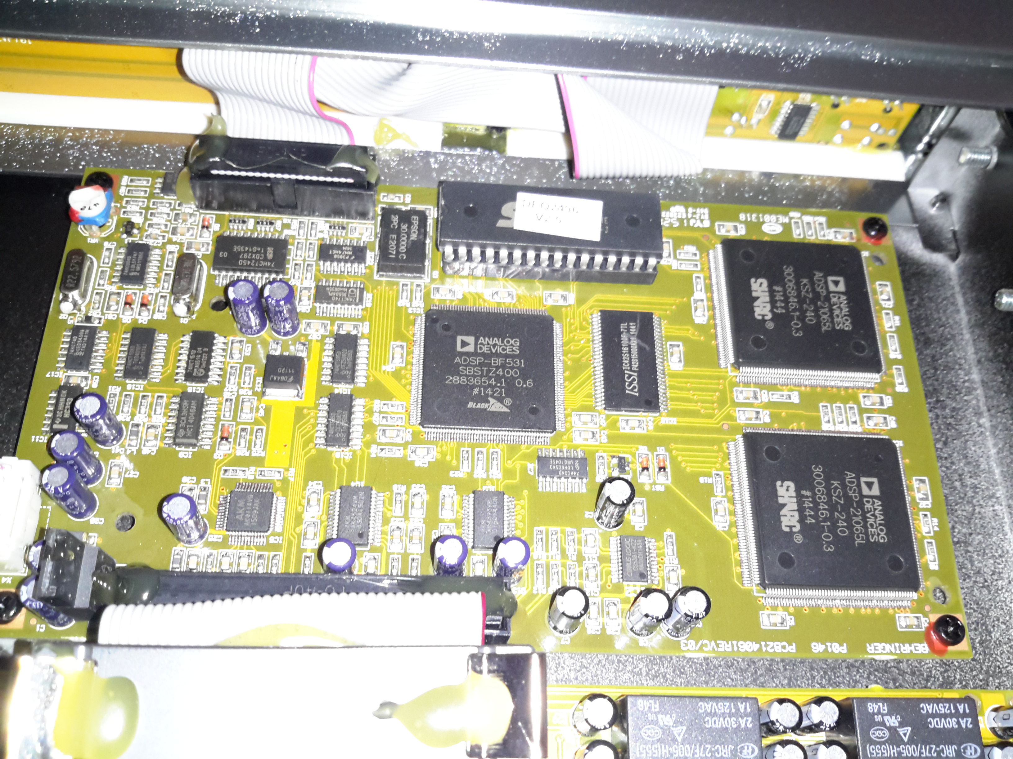
Main Processor PCB
All the magic is done on the main processor PCB, which is host to 3 Analog Devices DSP processors:
ADSP-BF531 BlackFin DSP. This one is probably handling most of the audio processing, as it’s the most powerful DSP onboard at 600Mhz. There’s a ROM on board above this for the firmware & a single RAM chip. On the right are a pair of ADSP-21065 DSP processors at a lower clock rate of 66MHz. To the left is some glue logic to interface the user controls & dot-matrix LCD.
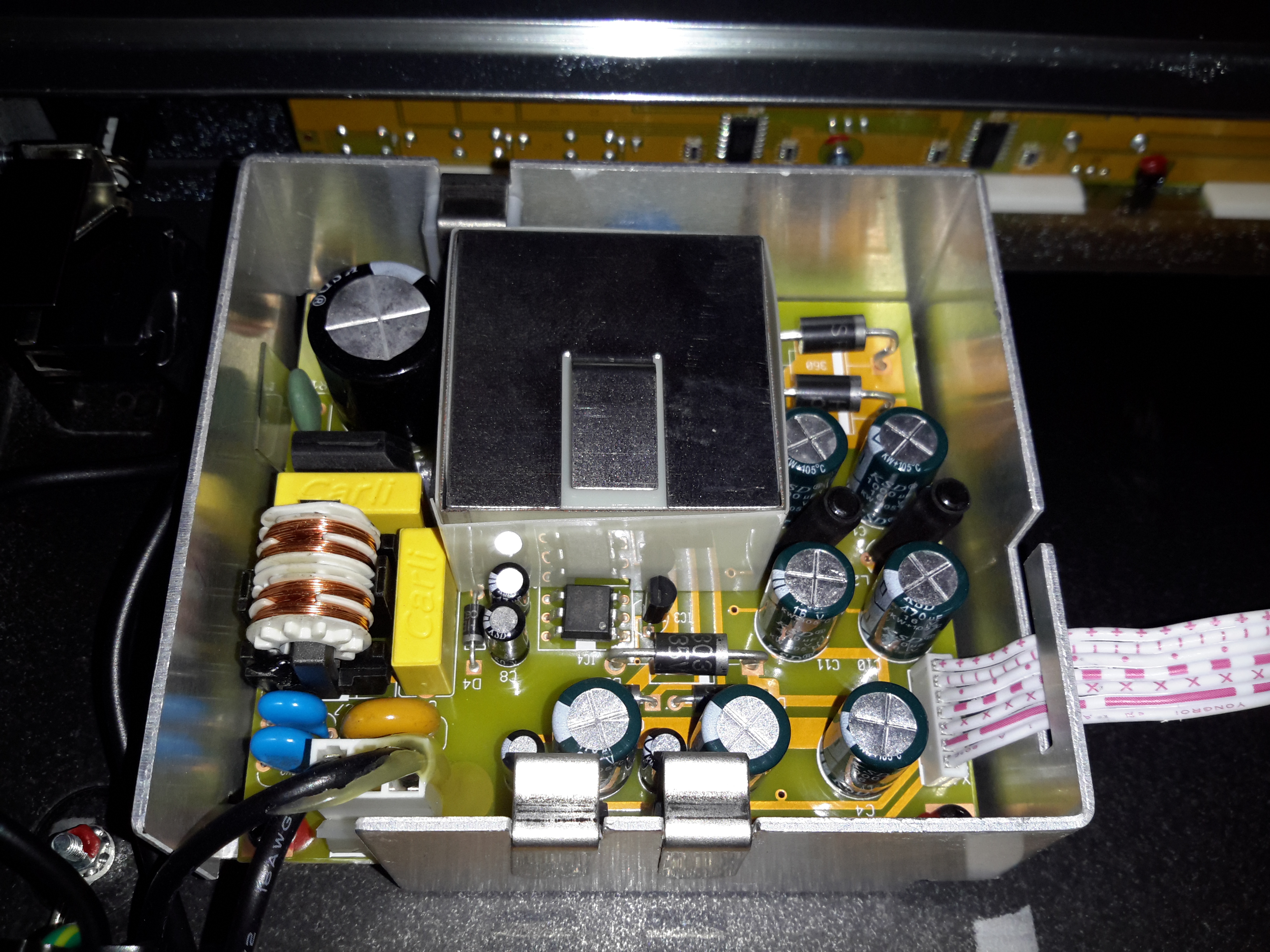
PSU Module
The PSU in this unit is a pretty standard looking SMPS, with some extra noise filtering & shielding. The main transformer is underneath the mu-metal shield in the centre of the board.
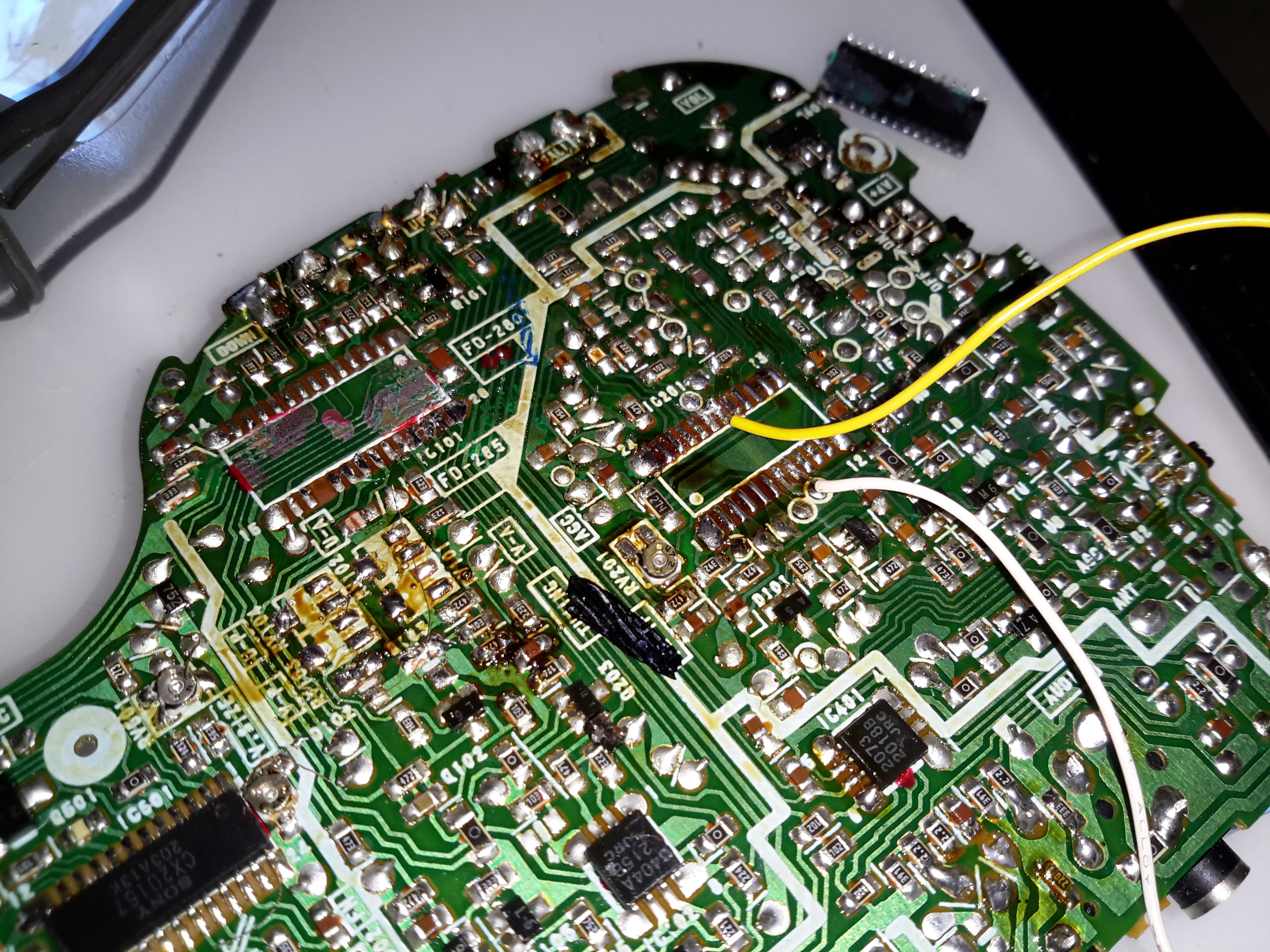
As with the previous Sony Watchman hack, injecting a composite video signal into this one is just as easy. I desoldered both the VIF/SIF IC & the digital tuner control (the tuner controller was still injecting it’s indicator into the video circuitry with the IF IC disconnected).
Composite video is on pin 18 of the Video IF IC, with the audio on Pin 13.
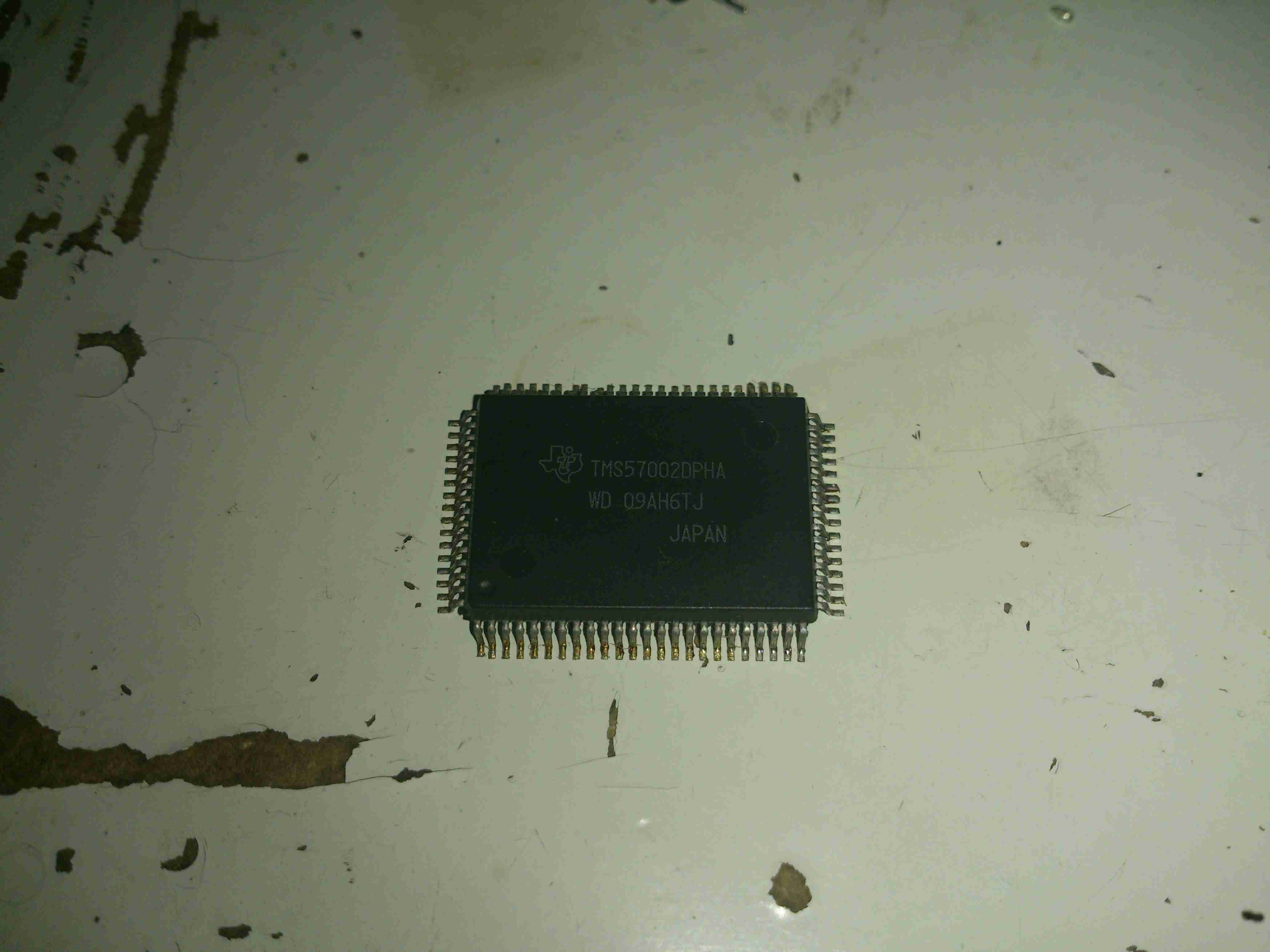
This is an Audio DSP chip from the early 90’s, used for sound effects in audio mixing consoles. Unfortunately I couldn’t find much info on these.
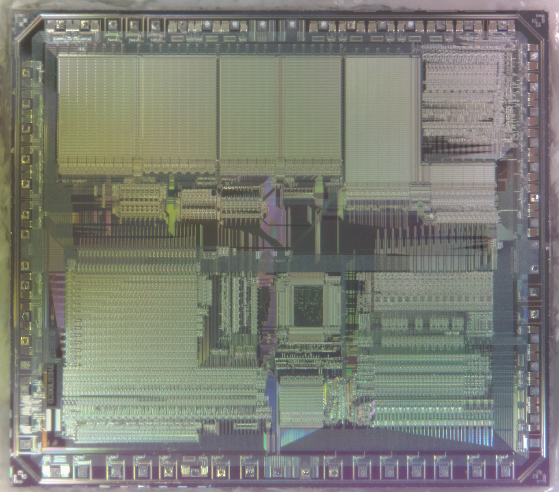
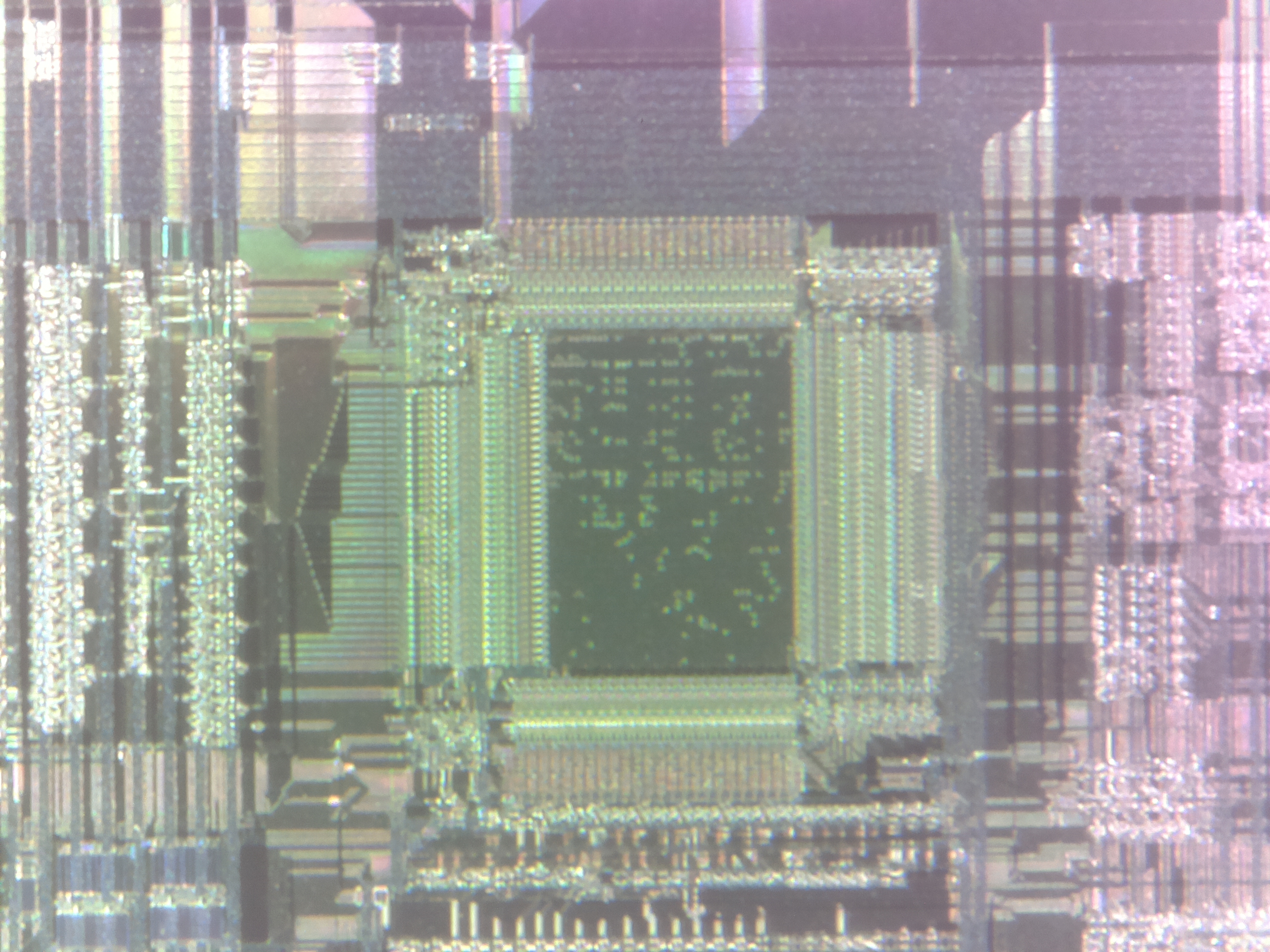
TMS57002 Die
The die is massive, 10mm square at least. Interestingly, the markings on the die indicate it’s a TMS67002, maybe there was a different internal software version for the 57002 with fewer features, that used the same Silicon? In the centre of this die, there’s an area that looks like mask ROM, with the individual memory bits visible.
It’s been a while since I’ve done a proper radio based post, so it’s a bit of a shame that I have to start off with a rant, but it’s required in this case.
One of the local 70cm repeaters, GB3WP seems to have many problems. The largest one seems to be G6YRK, the repeater keeper.
I had heard rumours of the repeater suddenly going off air getting switched off when either an M3/M6 or 2E0/2E1 was using it. At the time I thought no fellow ham could be quite that petty.
What callsign I or anybody else has should not make a shred of difference whether we should be allowed on the air or not. I personally keep my operating standards as high as possible, way above and beyond what Ofcom stipulates in the licence terms, as it’s part of making the hobby enjoyable for everyone. Seems that not everyone feels the same (in my experience, the older generation of hams, some of whom believe that the tests these days are far too easy, etc, etc).
Then I got proved wrong.
I was doing some handheld radio testing with M3HHY over at Distant Signal Radio on GB3WP, as at the time GB3MR was having some issues with the local pirate (see my previous posts for more info on that prat).
Within a couple of minutes of us establishing a QSO, the repeater suddenly stopped responding. After trying to get back in for a good 15 minutes, it came back on air again.
The instant we gave our callsigns, off it went, into the ether. No response.
This behaviour continued for nearly an hour, and after trying to contact YRK directly, we gave it up as a bad job, with quite a bit of pissed off added into the mix.
If I’d not heard stories of the repeater being turned off when the “wrong people” are using it, I might have put it down to dodgy repeater equipment, but even that didn’t make sense, as it had a definite pattern.
We both fired off an email to the Repeater Keeper, only to get no response from that either (surprise, surprise).
That was the last time I personally attempted to make use of GB3WP.
Until I was given an audio clip of G6YRK in action this evening.
Seems that not even M0 calls are immune from being wiped off the air by GB3WP. Chris, M0OGG, has apparently also had this issue with the repeater. Lucky for him, he had the opportunity to speak to the keeper directly about what went on.
Here’s the audio, I’ll pick each part out & go into a few opinions/observations below.
So, Chris (M0OGG) has asked a simple question, and been met with hostility. Dick Move Number 1.
YRK is clearly reluctant to go into “detail” on the air. Probably because he’s talking complete shite. Only when Lewis (M3HHY) joins in with a slightly more defensive tone does Steve (G6YRK) actually say what Chris has been “reported” for.
After all that it seems that an accusation of keying over other repeater users is the bullshit line of the day. (For the record, I know Chris, he’s not the type of person to key over another radio user, that behaviour in of itself is idiotic).
Apparently he has witnesses to this action, and he’s insisting that others were also involved. Not to mention the fact that RDF has been done on (I’m assuming) all of these “offenders”. G6YRK must have quite the army of hams with lots of spare time.
I’m not sure who the other station is, as he doesn’t give a callsign.
As Lewis jumps in & comments, the Repeater Keeper should be saying something to users he suspects of this kind of thing, in my opinion.
The real reason, of course, that he keeps turning the repeater off when others are using it is that he’s a passive-aggressive vindictive moron.
Surprise, surprise, he can’t remember the “exact date”, (because it never actually happened), it’s just “the other day, somebody did it”. Yeah, great evidence there Steve, because apparently the only person around at the time was Chris. How can he know this? When a repeater has a coverage area as wide as GB3WP, this guy is claiming that he knows that only a single person is listening? No, I think it’s bullshit too.
GB3WP Coverage Map
For reference, here’s the coverage map of the repeater. Steve G6YRK must be bloody psychic to make such a comment.
He then mentions a “friend” of Chris, but again refuses to give any names. Again I’m calling bullshit.
Swifty following this he goes into full kick-my-toys-out-of-the-pram mode because he’s been openly challenged.
While he’s correct in his statement that he can do as he pleases with the repeater, it’s not very good form to just switch the thing off when licenced users are having a perfectly valid QSO. If he doesn’t like people using the repeater, he should turn it off permanently & remove the listing from the repeater group.
After this, Steve makes the comment that he knows nothing of the repeater going off, as he’s been out all night. He mentions his Repeater Stasi again, and then makes a partial retraction of his previous statement, now that it “might” not have been Chris previously. Well Steve, we’re finally getting towards something that resembles truth. You’ve got absolutely no idea who is “keying people out”, if it’s even happening at all. So much for “having people all over the place” listening to where transmissions are coming from.
After Chris confronts him again, he returns to the fallback of that as the NoV holder it’s his prerogative to be able to switch the repeater off whenever he pleases.
When confronted with the fact that people pay into the repeater group to help keep them running, he claims that Chris’ signal is breaking up. My arse. Every other station on the repeater can hear him fine.
There’s probably more to add to this, so if I get any more relevant information from other sources I’ll add on to the saga.
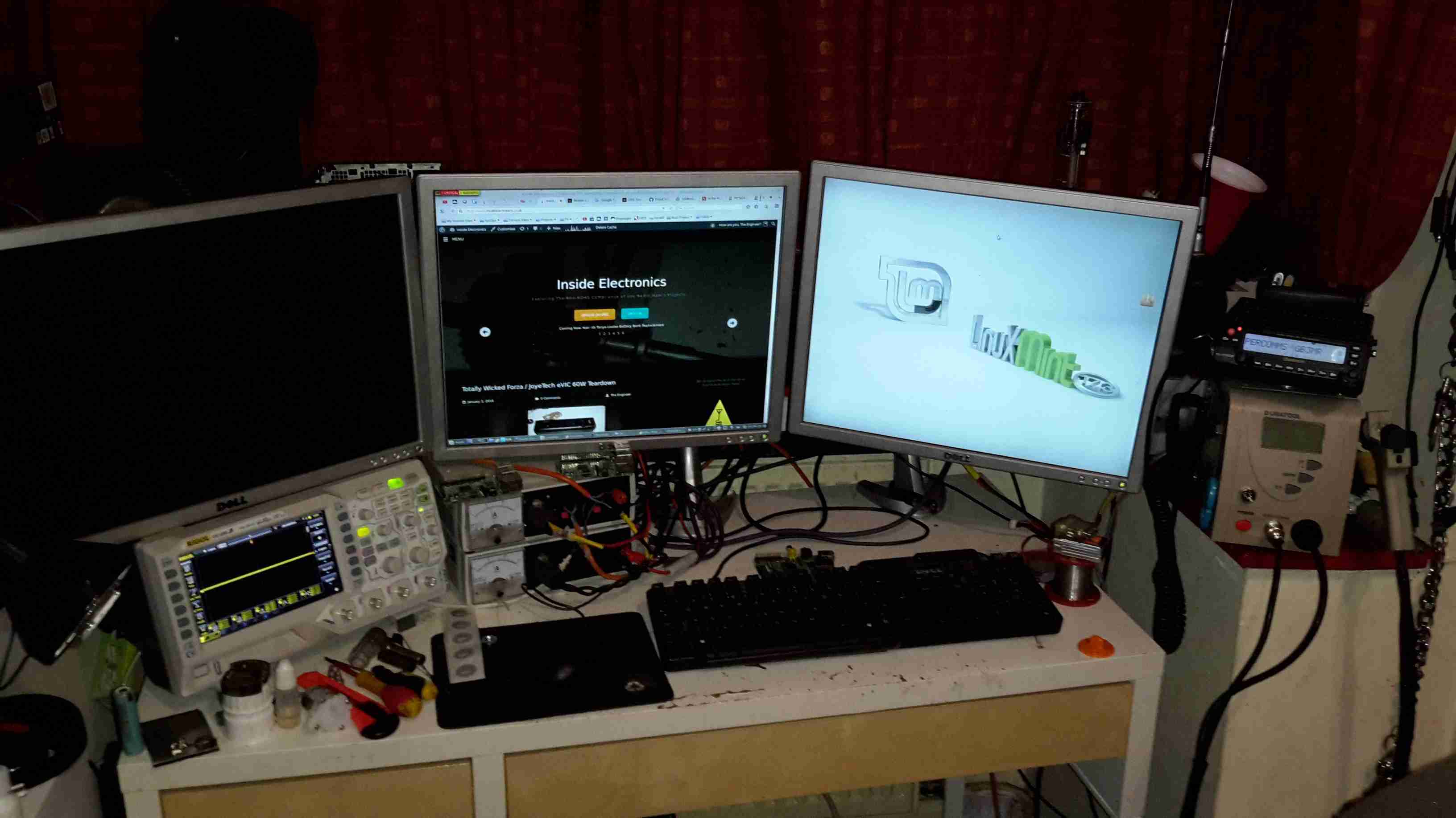
Main radio of course is housed on the left, it’s partially hidden under my currently over-populated breadboard.
All 3 monitors are linked to the same PC, using a pair of video cards. This is a very flexible system with so much screen real estate.
Main system power is provided by the pair of power supplies next to the radio – these are homebrew units using surplus switched mode PSU boards. Check my previous posts for more details.
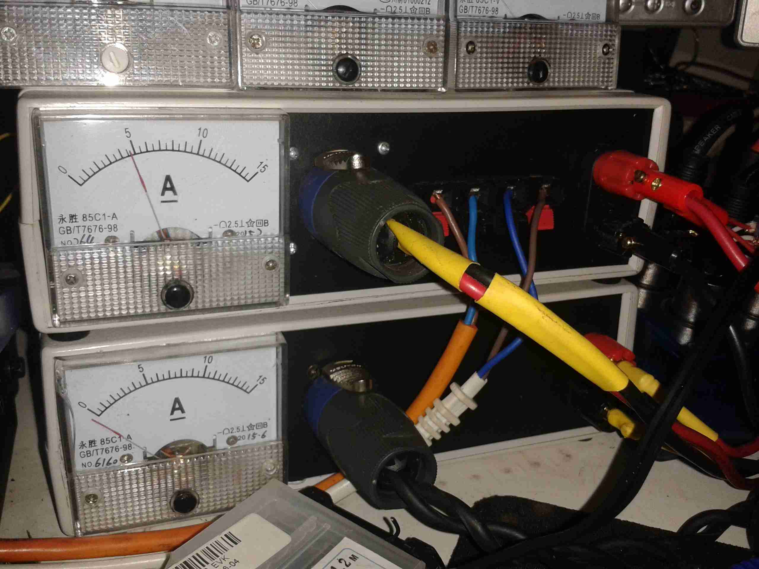
Power Supplies
The mainpowersupply system. These two supplies are cross connected, giving a total DC amperage of 30A at 13.8v. There is also a link to a large 220Ah lead-acid battery bank (orange cable), to keep me on the air during power outages. This cable is getting upgraded to something more beefy shortly. The white cable is currently supplying power to my onlineradiation monitor.
The main high-currentDC outputs are the Speakon connectors next to the meters. The top one is powering the radio directly, the bottom is linked through to my 12v distribution box for lower current loads, such as the oscilloscope, audio amplifiers, tools, etc.
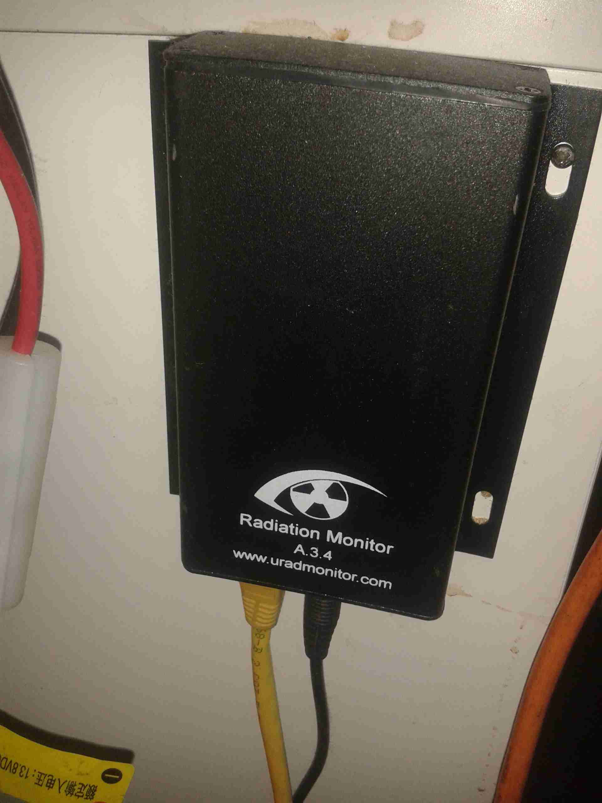
Radiation Monitor
Attached to the side of the desk is the radiation monitor itself.
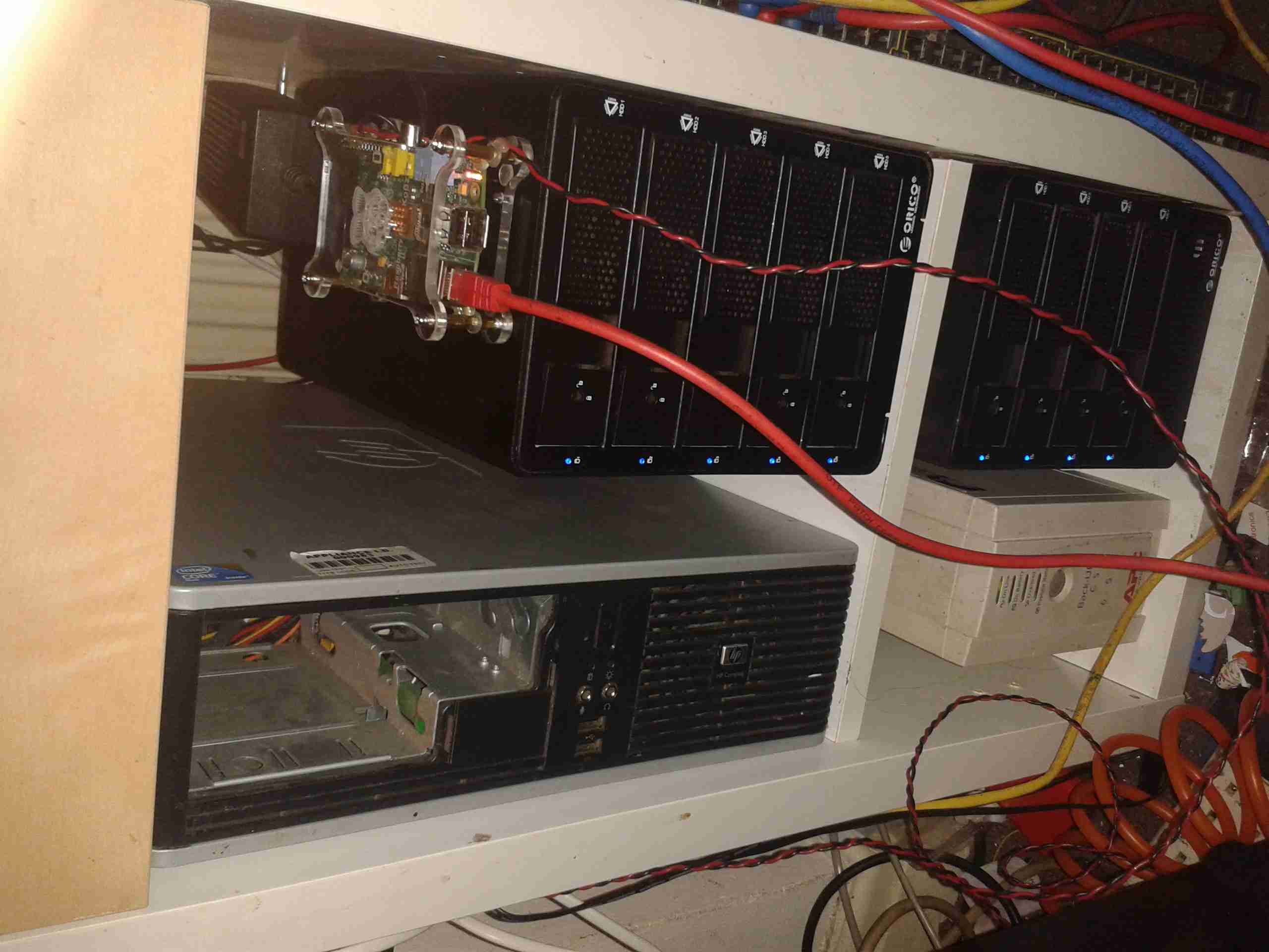
Core NAS
Under the radio is the core NAS of the network. It’s an array of 9 4TB disks, in RAID6, giving a total capacity after parity of 28TB. This provides storage & services to every other machine in the shack, the Raspberry Pi on top of the disk array is doing general network housekeeping & monitoring, also generating the graphs for the Radiation Monitor page. A Cisco 48-portswitch is partially out of frame on the right, providing 100MB Ethernet to the devices that don’t require gigabit.
I’ve had a couple of viewfinder CRT modules for a while, & haven’t done much with them, so I decided to make a very small B&W monitor.
CRT
I ordered a small transparent ABS box when I made a large order with Farnell, that turned out to be just about the perfect size for the project! The CRT & PCB barely fit into the space. The face of the CRT itself is about 17mm across.
Module Installed
Here’s the main PCB & tube fully installed into the case. Barely enough room for a regulator left over!
Power is provided by a simple LM7809 IC to take a standard 12v input.
Module Rear
Rear of the case, showing the fit of the control board.
Connections
Here’s the back of the monitor, with the DC input jack & a 3.5mm 4-pole jack for audio & video. This allows simple connection to many devices, including the one I’ll use the most – the Raspberry Pi.
Completed
Completed monitor. Audio is handled by a very small 20mm speaker, currently mounted just below the CRT face.
Current draw from a 13.8v supply is 117mA.
Now this is amusing, captured tonight on GB3MR, the usual unlicenced plonker is now threatening us all on the air with the Police – not sure where he’s getting a criminal offence out of the fact that everyone on the repeaters is moving around to avoid him, but still. Nor is it an offence to share audio of Amateur Radio transmissions – they’re considered public domain.
Here’s the audio for your listening pleasure.
I caught even more abuse on the local repeater this afternoon, this went on for a long time, into the early hours of the morning, having a conversation with himself as per usual. By the sounds of it alcohol was involved, the speech got more slurred as time went on. As usual, here’s the audio for your listening pleasure 🙂
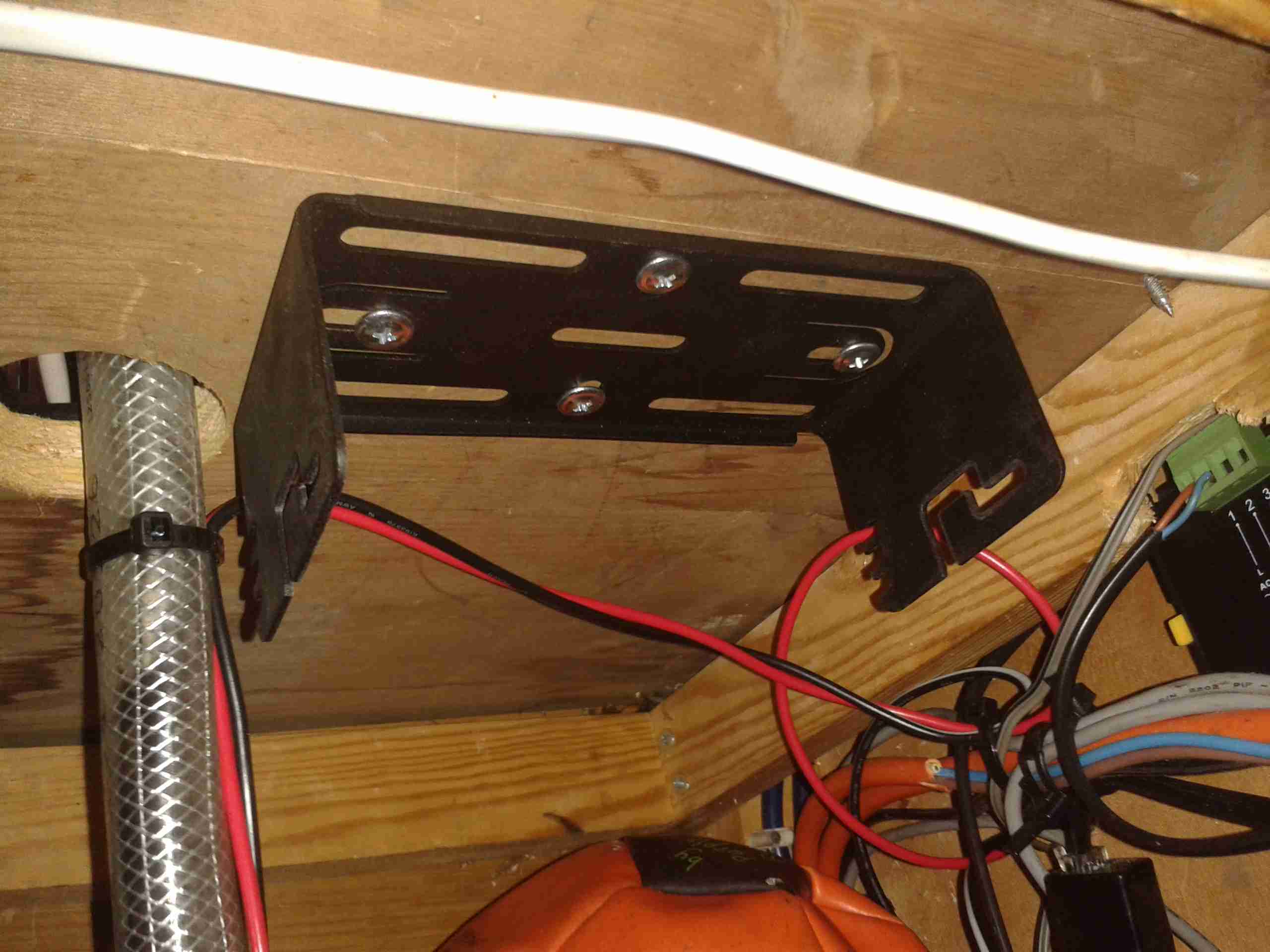
I often find myself carrying by go bag up to the boat during trips, so I can do some radio. However at 16lbs it’s a pain on public transport. A fixed radio was required! Another Wouxun GK-UV950P was ordered, and the fact that the head unit is detachable from this radio makes a clean install much easier.
Mounting Bracket
I found a nice spot under a shelf for the main radio unit, above is the mounting bracket installed.
This location is pretty much directly behind where the head unit is placed, but the audio is a bit muffled by the wooden frame of the boat & some external speakers will be required for the future.
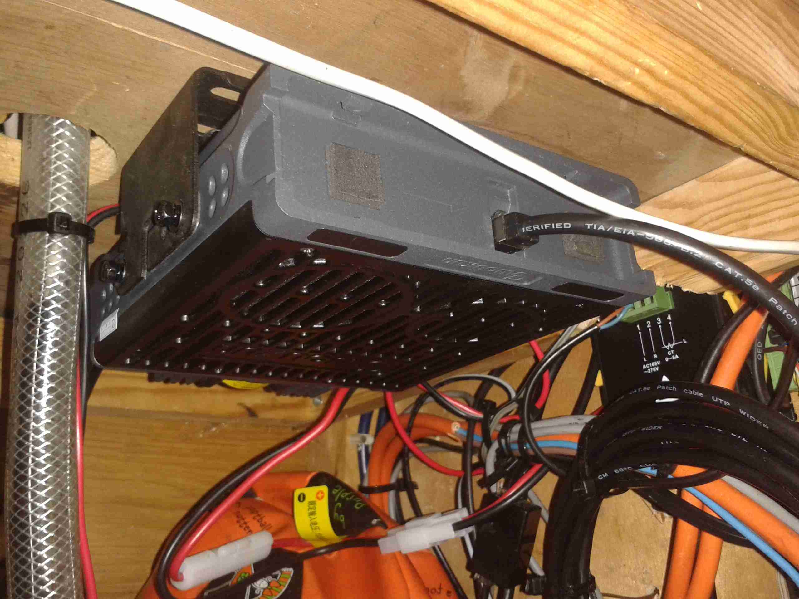
Main Radio Unit
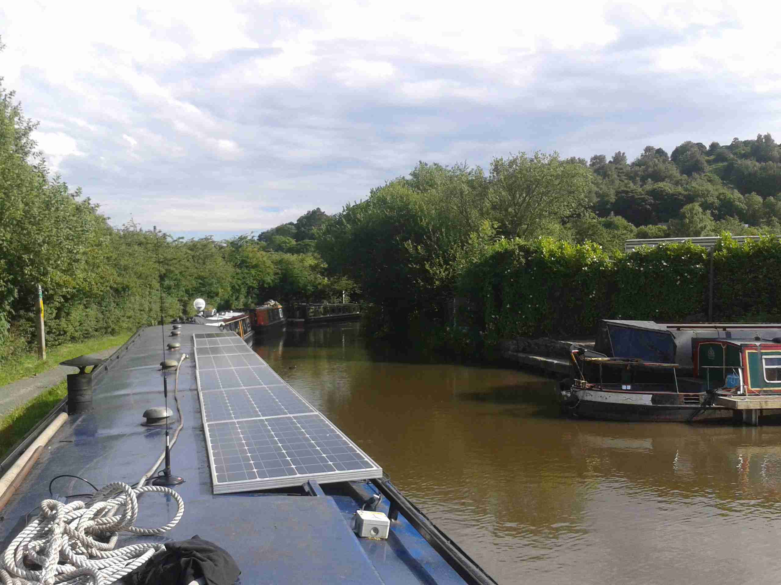
Here’s the main radio unit mounted on it’s bracket, with the speakers facing down to improve the audio slightly. I used the supplied interface cable for the head unit, even though it’s too long. I do have the tools to swage on new RJ-45s, but the stuff is a pain to terminate nicely & I really just couldn’t be bothered. So it’s just coiled up with some ties to keep it tidy. Main power is provided directly from the main DC bus. (880Ah total battery capacity, plus 90A engine alternator, 40A solar capacity).
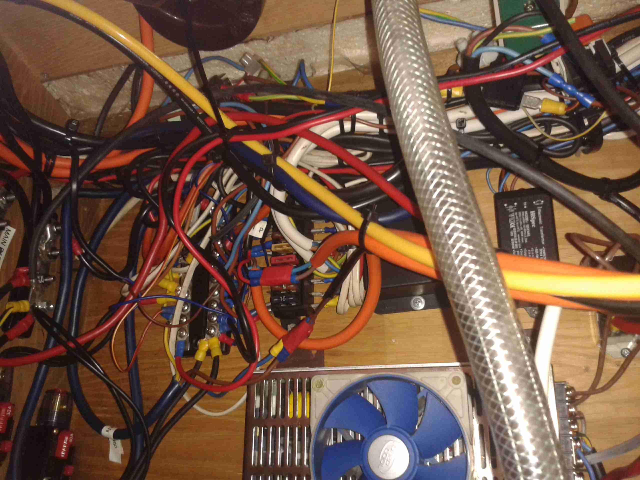
Rat’s Nest
Here’s the main DC bus, with the distribution bars. With the addition of new circuits over the years, this has become a little messy. At some point some labelling would be a good idea!
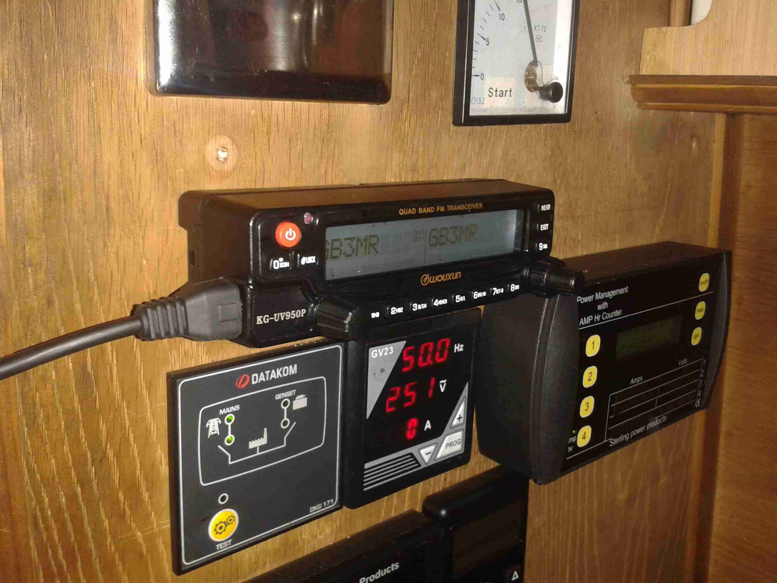
Radio Face Plate
Finally, the head unit is installed in a spot on the main panel. It does stick out a little more than I’d like, but it’s a lot of very dusty work with the router to make a nice hole to sink it further in. All my local repeaters & 2m/70cm simplex are programmed in at the moment.
Antenna Magmount
I’ve got a Nagoya SP-80 antenna on a magmount for the radio, a magmount being used due to the many low bridges & trees on the canal. (It’s on the roof next to the first solar panel above). I prefer it to just fall over instead of having the antenna bend if anything hits it!
Part 2 will be coming soon with details of the permanent antenna feeder.
Here we go again with the GB3MR local idiot. He does always try to get a response from people, but we seem to be able to filter out this crap. 🙂 Here’s the audio for your listening pleasure. 🙂
I think the headline speaks for itself… The usual group, with their Baofengs… Grossly over on the power!
After this, they then went up to 446.070MHz, which is in the guard band between channels. All the while admitting they’re using massive high gain antennas as well.
Shortly after, they went over to 446.065MHz, still between the channels, but it’s close enough to have splatter all over the place. So in trying to get on a frequency that can’t easily be heard on PMR (in their opinion), all that they’ve accomplished is interfering with two separate channels at the same time! Here’s the aftermath of their channel switching on 446.065MHz.
Here’s some audio from last night on PMR, the regular group seem to be getting a little hacked off 🙂
(I do love the way these guys go on about abuse on the band when they’re transmitting on enough power to rival the BBC, they mustn’t know that PMR446 is limited to 500mW, the Baofengs they’re using only go as low as 1W, usually more when measured).
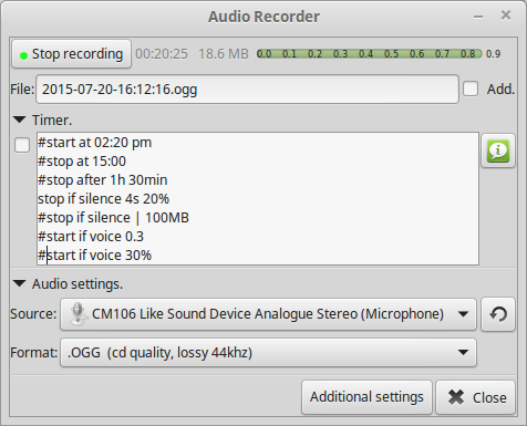
Since my new Wouxun has audio output jacks, I figured it would be useful to have the ability to record what my rig hears, if anything interesting comes on the air.
Under Linux, I use an application called, (creatively enough), Audio Recorder.
Recorder Screenshot
Using a simple connection to the mic input on a USB soundcard, I can capture everything the radio hears. Unfortunately this doesn’t work for outgoing audio, so it’s not much good at capture of my personal QSOs. For this I will have to set up another radio to act as the main receiver.
At some point in the future I will implement this with a Raspberry Pi as the audio capture server.
I’ve been doing some tinkering with the RN-52 Bluetooth Audio module from Roving Networks, in prep for building a portable wireless speaker system, & thought I’d share my designs.
Initially I was having some issues with RF noise on the audio output from the RN-52, as I was only using the outputs single-ended. The module didn’t like this treatment, with all the RF whine coming straight out of the speakers.
To fix this issue I have used a pair of jellybean LM386 audio power amplifiers, running in differential input mode. This solves the high-pitched whine when the audio is enabled, & also allows the module to directly drive a set of 32Ω headphones at a reasonable level.
In Eagle I have designed a simple board, routing only the audio output, serial TTL & command mode pins out, along with the supporting power supply circuitry to operate from 12v DC.
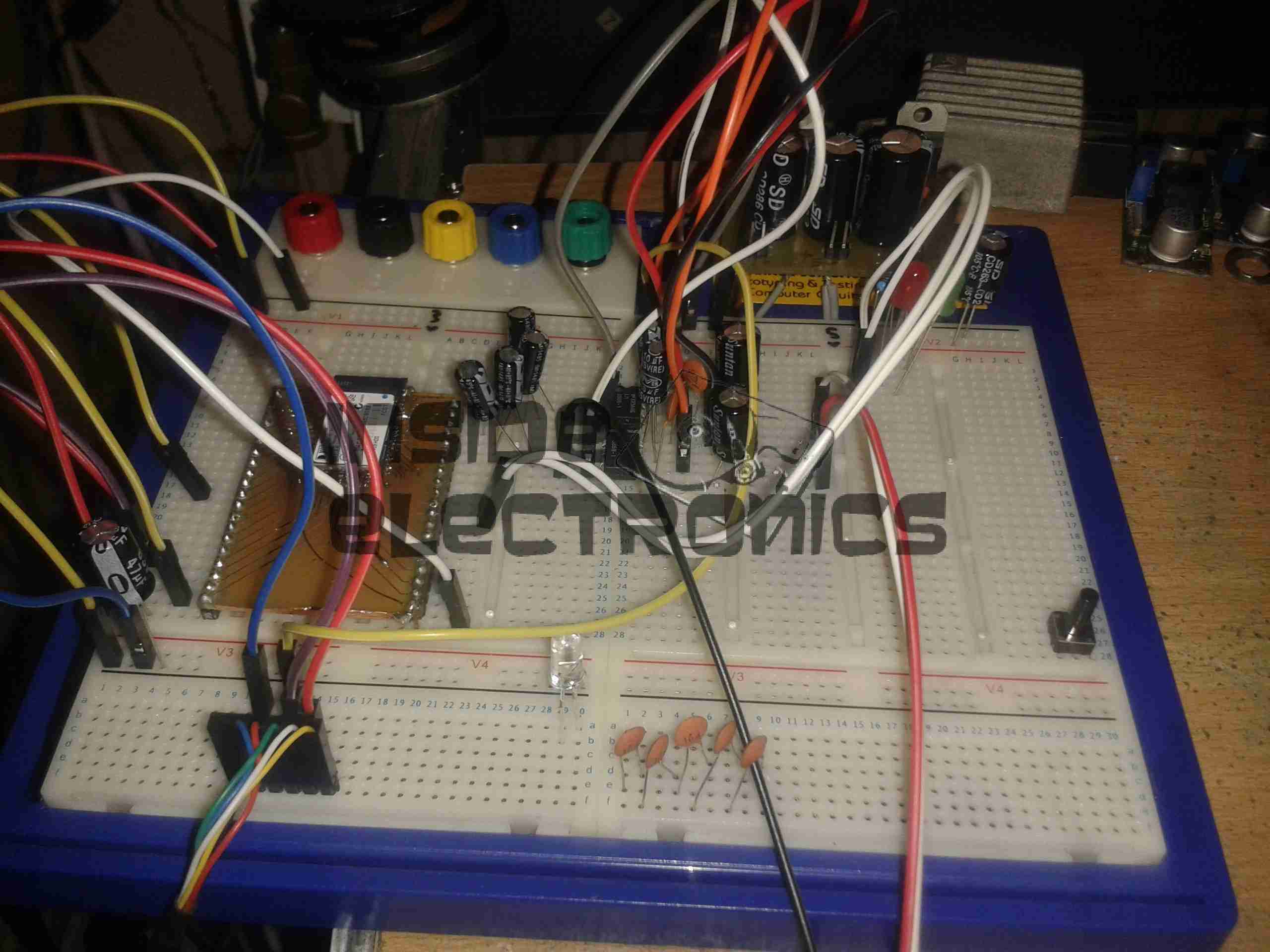
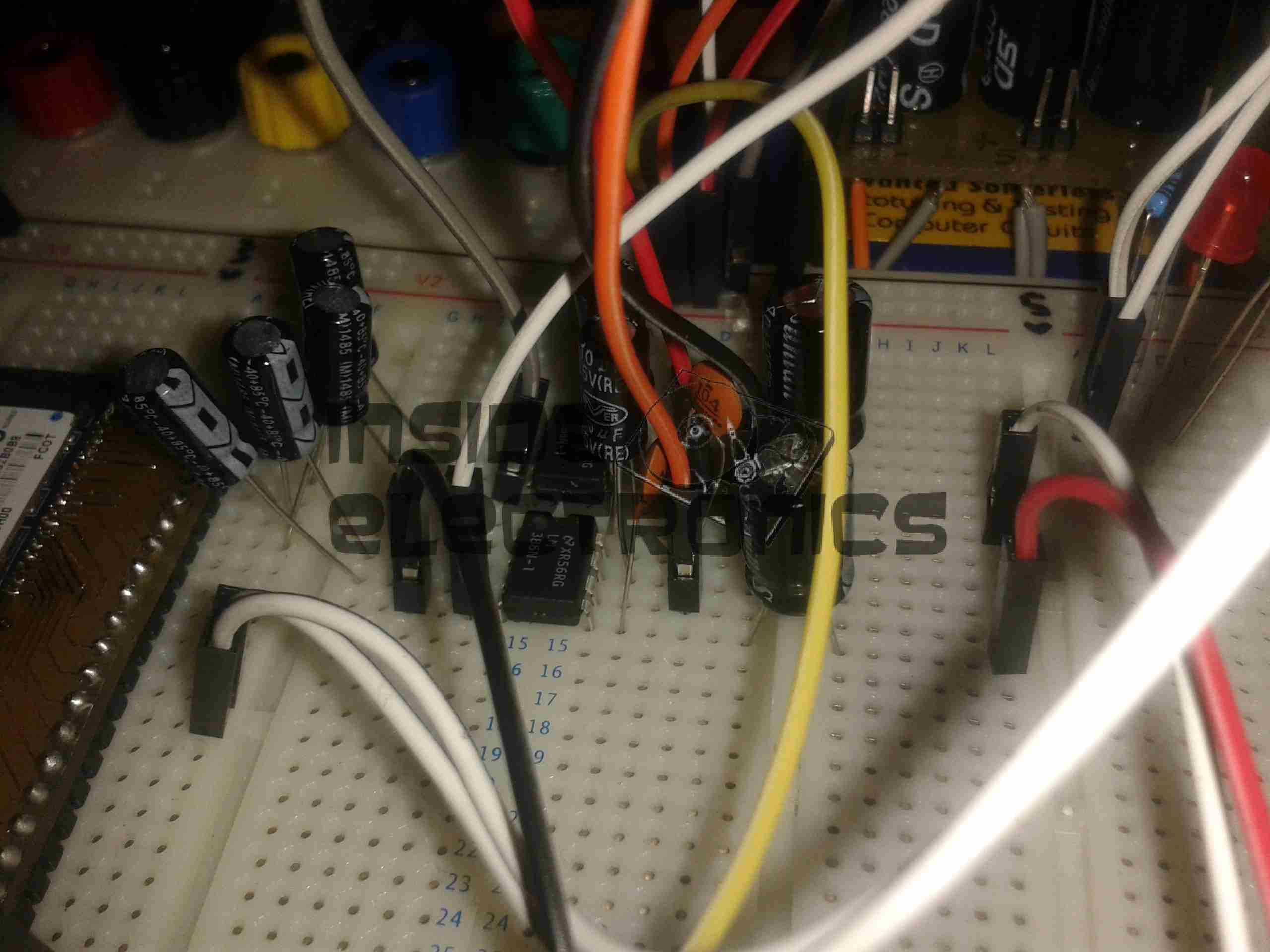
RN-52 Breadboard
Above is the current incarnation of the circuit on the breadboard. The RN-52 is on the left, audio power stage in the centre & headphone output on the right.
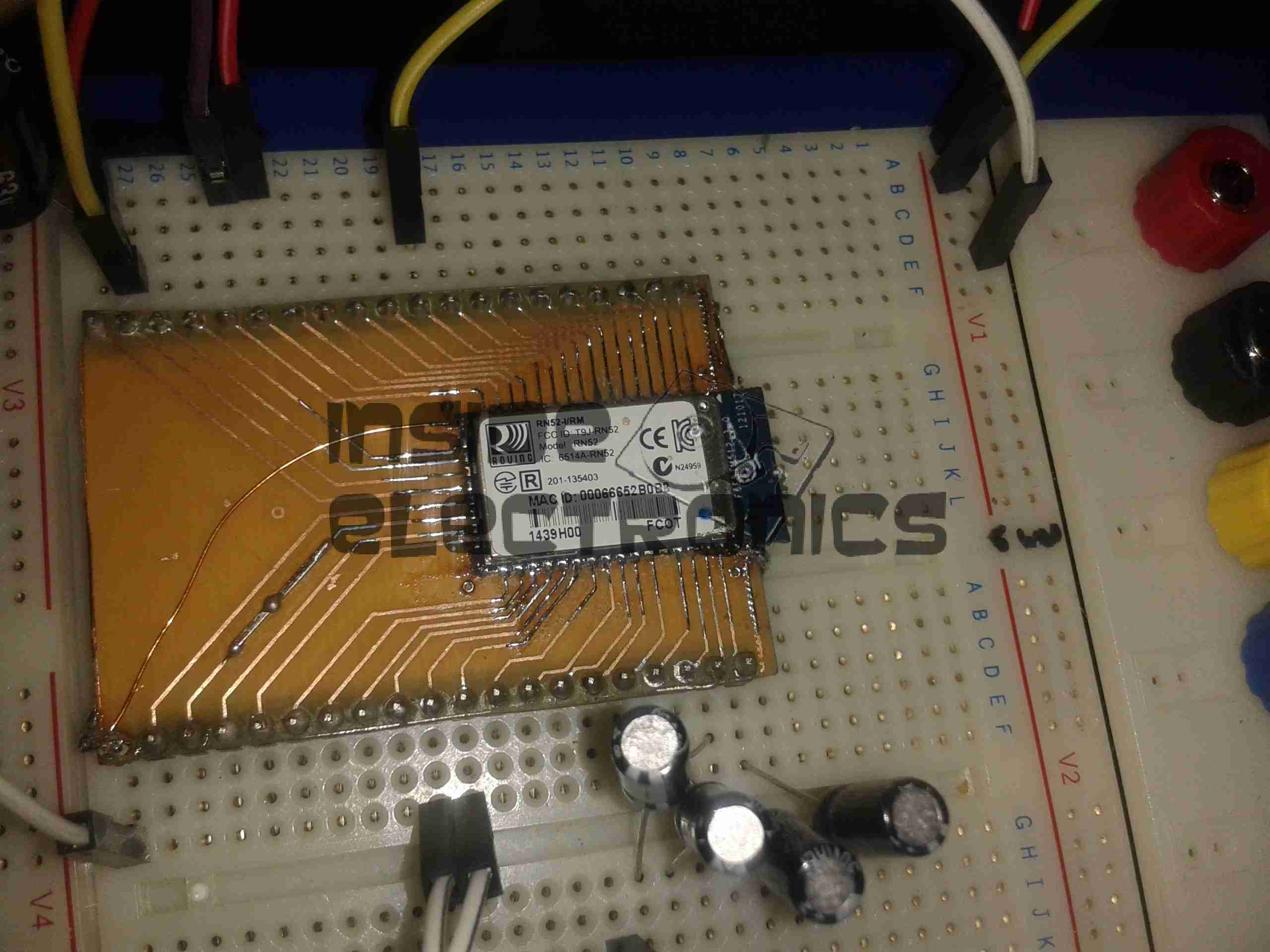
RN-52 Breakout
The bluetooth module on a breakout board. I was cheap in this case & etched my own board. I’m not paying Sparkfun, (as much as I like them), an extra ~£10 for a small PCB with the pins broken out. Much cheaper to spend 15 minutes with the laser printer & the iron, & do a toner transfer PCB.
As this board is single sided, I added a ground plane on the underside with copper foil, to help with the RF issues. Breadboards really aren’t all that good at rejecting noise induced when there’s a 2.4GHz transceiver mounted on them.
LM386 Amplifier
The LM386 audio power stage. The differential inputs from the module are capacitively coupled with 1µF electrolytics. This setup remarkably reduced the noise on the output. I left these at their default gain of 20, as I’ll be connecting another high power amplifier stage to drive large speakers.
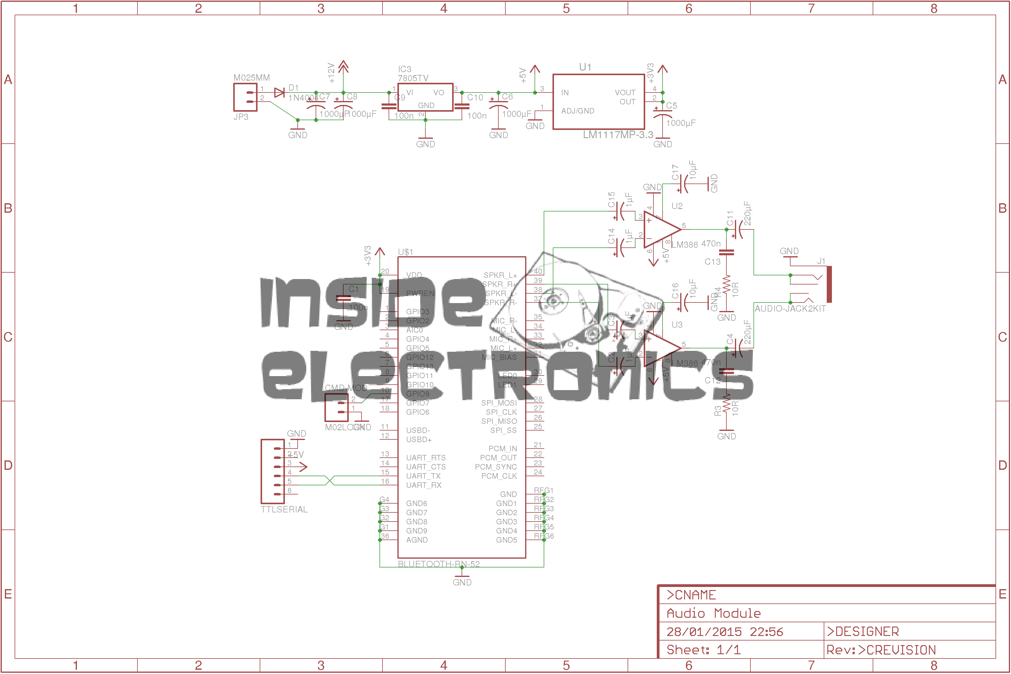
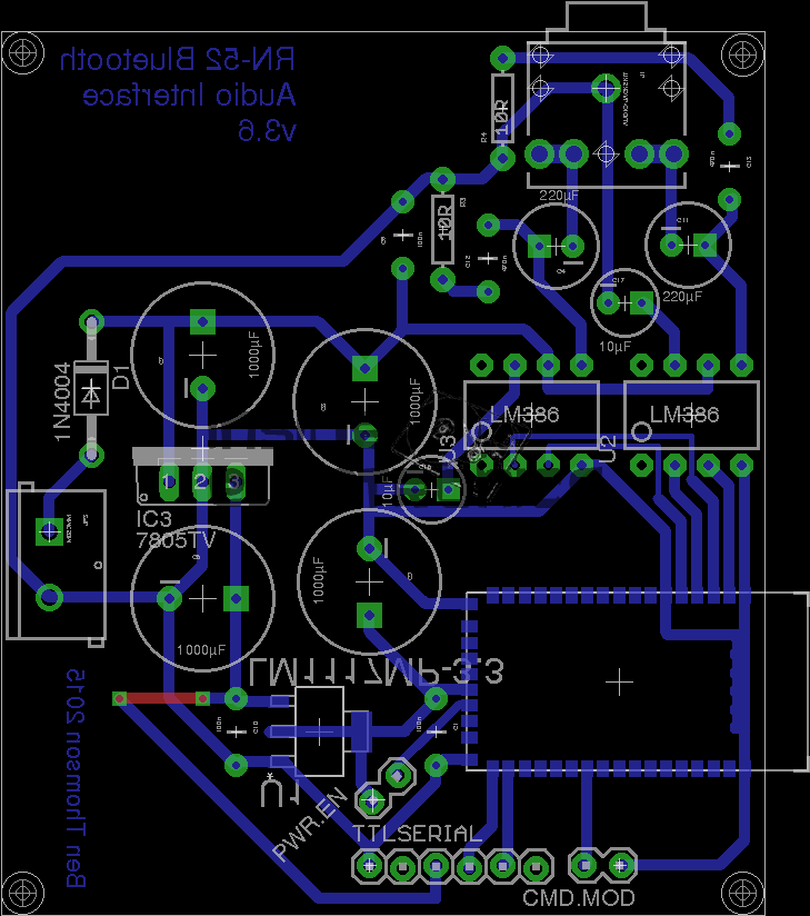
RN-52 Eagle Layout
Here’s the circuit laid out in Eagle, ready for PCB.
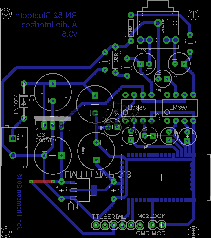
RN-52 Eagle PCB
And here’s the PCB layout. Only one link required for the +5v line from the TTL serial port.
As always, the Eagle PCB & Schematic layout files are available at the bottom of the article.
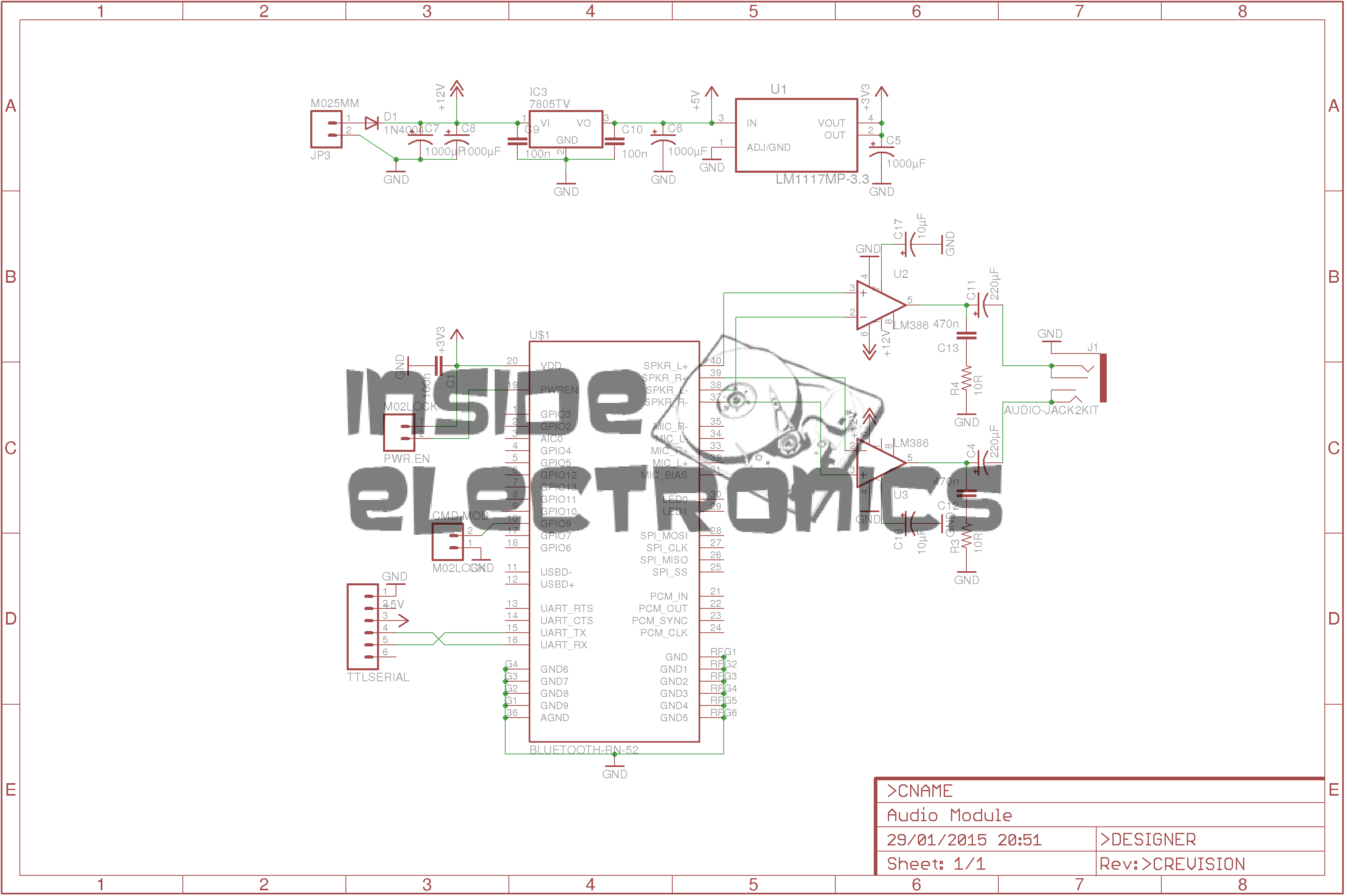
*Update 29-01-15*
Rerouted a few things:
Moved the audio power stage to the +12v rail to improve sound response. – As the LM386 has a max input voltage of 12v (absolute maximum 15v), a regulated supply is recommended. The LM386-N4 variant has a higher voltage range, up to 18v. This should be suitable for an unregulated supply.
Removed 1µF coupling capacitors to reduce distortion & amplifier hiss. The capacitors appeared to cause some instability on the amplifier, causing random distortion. Removing them has cured this. No signal hiss has also been reduced to a very low level.
Reversed input polarity on input of one of the amplifiers – this appears to produce better audio.
Added PWR.EN header to allow connection of power button. Saves hassle of cycling power to the board when the RN-52 goes into sleep mode.
As the first USB hub I was using was certainly not stable – it would not enumerate between boots & to get it working again would require waiting around 12 hours before applying power, it has been replaced. This is a cheapie eBay USB hub, of the type shown below.
These hubs are fantastic for hobbyists, as the connections for power & data are broken out on the internal PCB into a very convenient row of pads, perfect for integration into many projects.
Breakout Hub
I now have two internal spare USB ports, for the inbuilt keyboard/mouse receiver & the GPS receiver I plan to integrate into the build.
These hubs are also made in 7-port versions, however I am not sure if these have the same kind of breakout board internally. As they have the same cable layout, I would assume so.
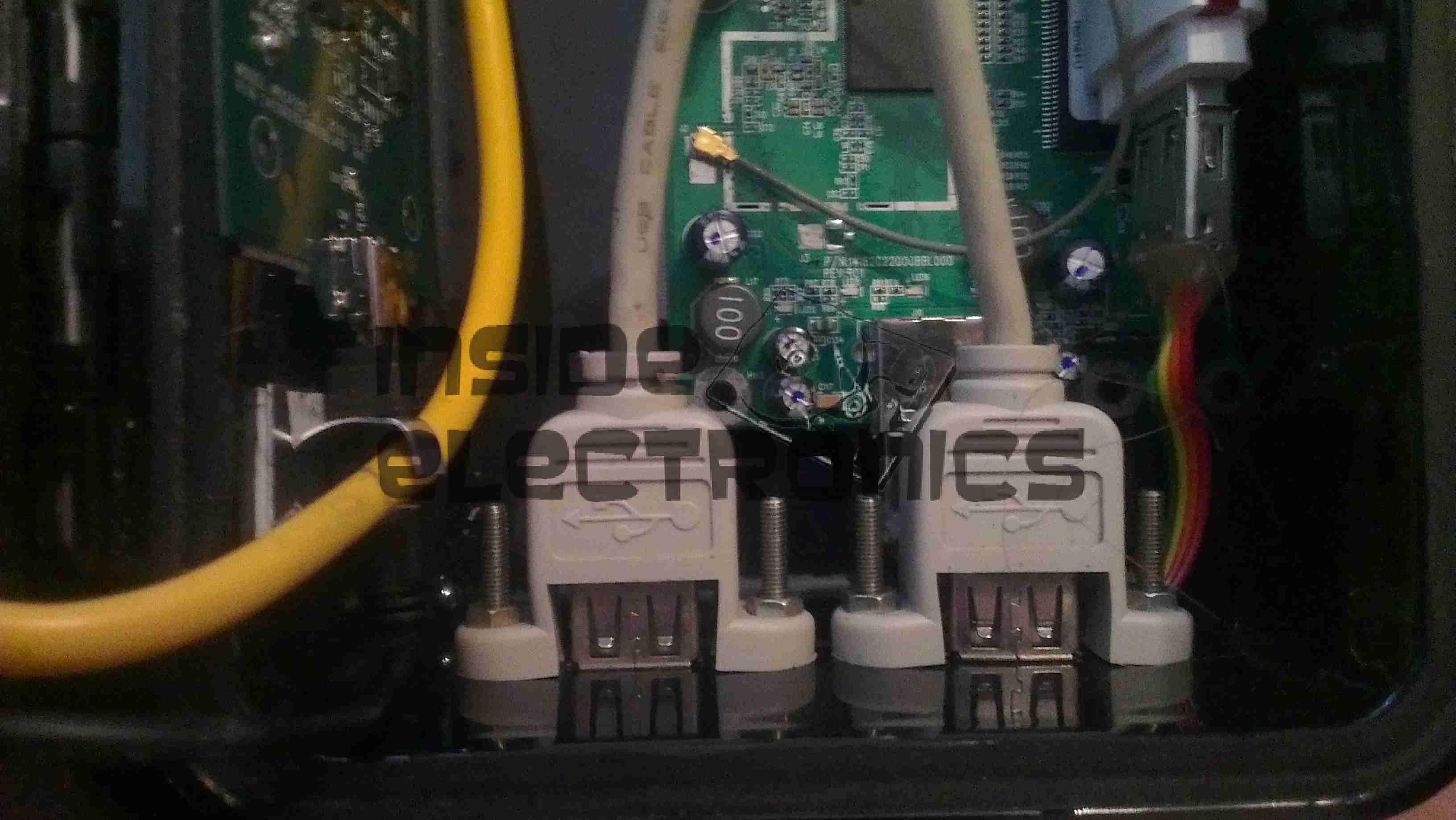
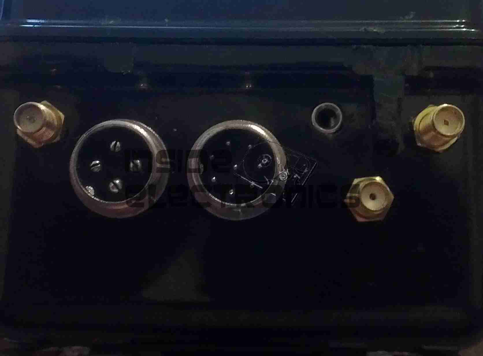
Connector Panel
Here is a closeup of the back of the connectors, showing a couple of additions.
I have added a pair of 470µF capacitors across the power rails, to further smooth out the ripple in the switching power supply, as I was having noise issues on the display.
Also, there is a new reset button added between the main interface connectors, which will be wired into the pair of pads that the Raspberry Pi has to reset the CPU.
This can be used as a power switch in the event the Pi is powered down when not in use & also to reset the unit if it becomes unresponsive.
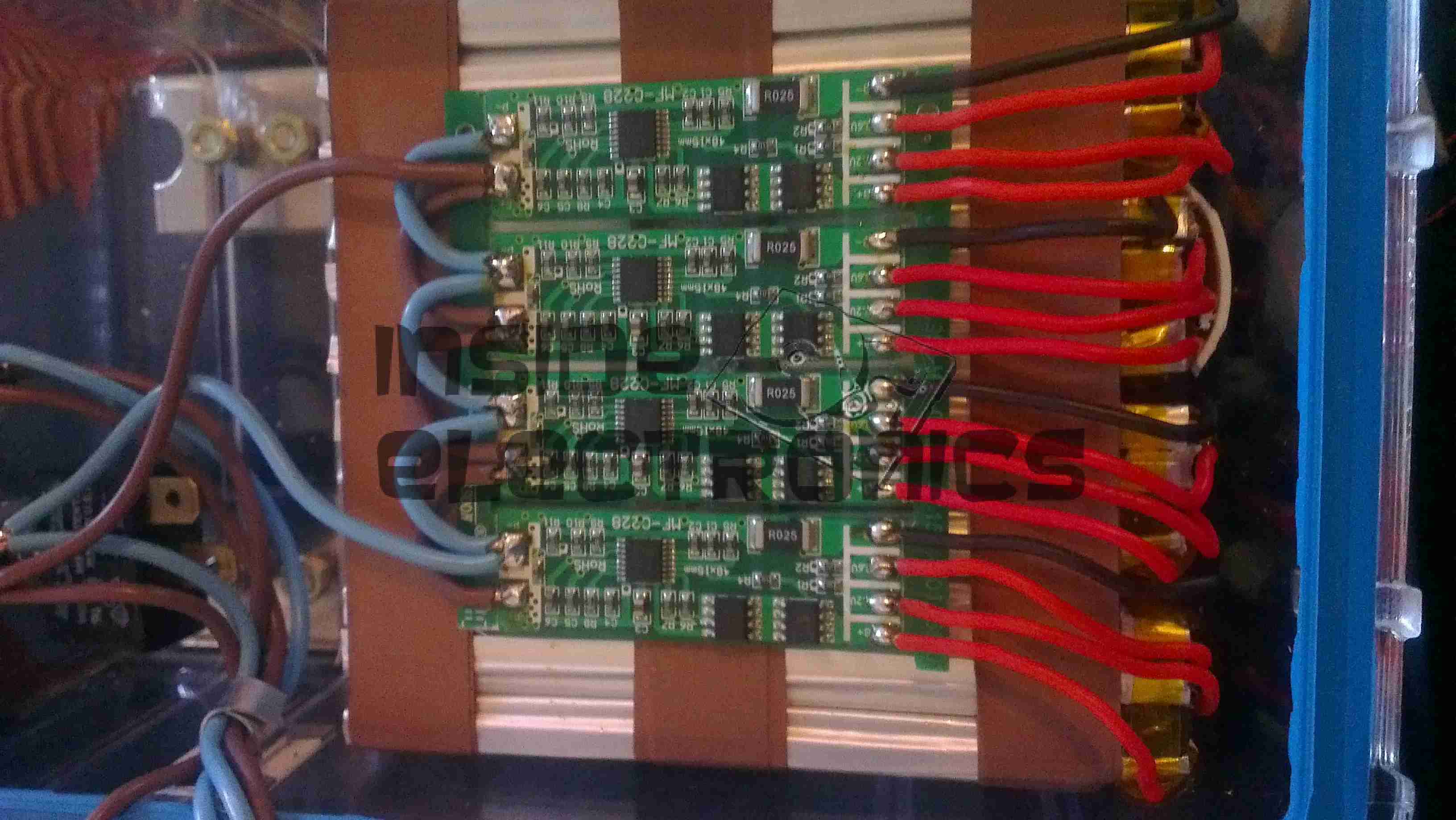
The final part for the battery pack has finally arrived, the PCM boards. These modules protect the cells by cutting off the power at overcharge, undercharge & overcurrent. Each cell is connected individually on the right, 12v power appears on the left connections. These modules also ensure that all the cells in the pack are balanced.
A few modifications were required to the SMPS modules to make the power rails stable enough to run the Pi & it’s monitor. Without these the rails were so noisy that instability was being caused.
I have replaced the 100µF output capacitors & replaced them with 35v 4700µF caps. This provides a much lower output ripple.
There are also heatsinks attached to the converter ICs to help spread the heat.
Progress is finally starting on the power supply unit for the Pi, fitted into the same case style as the Pi itself, this is an 8Ah Li-Poly battery pack with built in voltage regulation.
Regulator Boards
Here are the regulators, fixed to the top of the enclosure. These provide the 12v & 5v power rails for the Pi unit, at a max 3A per rail.
Battery Pack
In the main body of the case the battery pack is fitted. This is made up of 4 3-cell Li-Poly RC battery packs, rated at 2Ah each. All wired in parallel this will provide a total of 8Ah at 12.6v when fully charged.
Powered Up
Here the regulators are powered up from a 13v supply for testing. I have discovered at full load these modules have very bad ripple, so I will be adding extra smoothing capacitors to the power rails to compensate for this.
I/O
Here are the connectors on the top of the unit, outputting the two power rails to the Pi & the DC barrel jack that will be used to charge the pack.
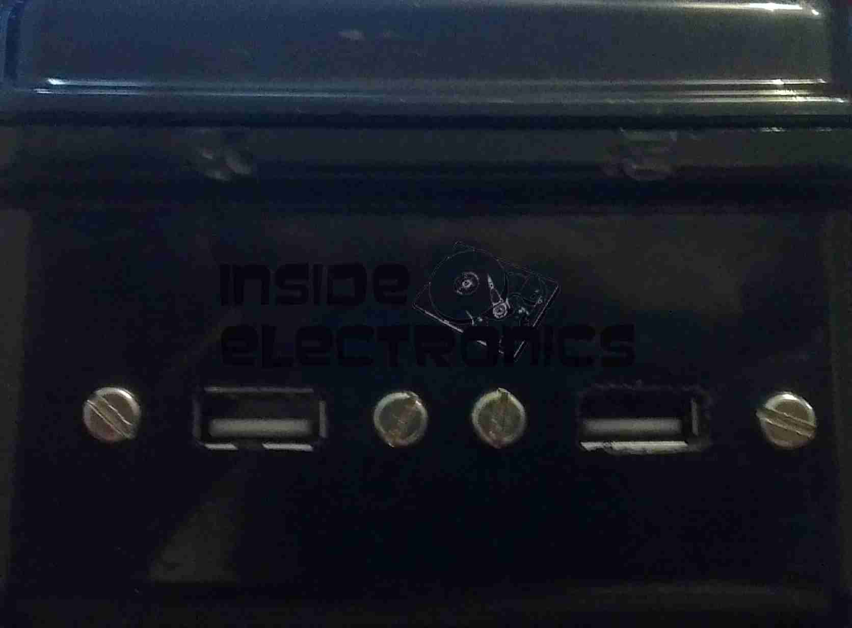
For convenience, a pair of USB ports have been fitted to the wearable Pi, which open on the bottom of the unit. These will be hardwired into a 4-port USB hub which will also support the wireless adaptor for the mini-keyboard that is to be used with the device.
USBs
The two USB ports on the bottom of the casing.
External Connections
The external connectors are also complete. The audio jack & second WiFi antenna port are fitted.
The audio is normally routed to the LCD display speaker, until a jack is plugged into the 3.5mm socket.
Here is the project I’m currently working on. A completely wearable computing platform based on the Raspberry Pi & the WiFi Pineapple.
Above can be seen the general overview of the current unit.
On the left:
Alfa AWUS036NHA USB High Power WiFi Network Interface
512MB Model B Raspberry Pi, 16GB SD card, running Raspbian & LXDE Desktop. Overclocked to 1GHz.
On the right:
WiFi Pineapple router board
USB 3G card.
The WiFi, Pineapple & 3G all have external antenna connections for a better signal & the whole unit locks onto the belt with a pair of clips.
The Raspberry Pi is using the composite video output to the 7″ LCD I am using, running at a resolution of 640×480. This gives a decent amount of desktop space while retaining readability of the display.
The case itself is a Pelican 1050 hard case, with it’s rubber lining removed. The belt clips are also a custom addition.
Connections
Here are the connections to the main unit, on the left is the main power connector, supplying +5v & +12v DC. The plug on the right is an 8-pin connection that carries two channels of video, mono audio & +12v power to the display.
Currently the only antenna fitted is the 3G.
Connectors
Closeup of the connections for power, audio & video. The toggle switch is redundant & will soon be replaced with a 3.5mm stereo jack for headphones, as an alternative to the mono audio built into the display.
Test Run
Current state of test. Here the unit is running, provided with an internet connection through the Pineapple’s 3G radio, funneled into the Pi via it’s ethernet connection.
Pi Goodness!
Running on a car reversing camera monitor at 640×480 resolution. This works fairly well for the size of the monitor & the text is still large enough to be readable.
Stay tuned for Part 2 where I will build the power supply unit.
This will be the record of building a new Media PC, above you can see the finished system.
It’s Mini-ITX based, with on-board HDMI output, specifically to run XBMC via Fedora for media purposes.
CiC MTX001B Mini-ITX Case
This is the case that is being used, around the size of a Shuttle PC. It has a single 3.5″ & 5 1/4″ bay, for a HDD & ODD, front panel USB, Firewire & Audio.
Intel BLKDH57JG Mini-ITX Motherboard
Motherboard to fit the case. Supports Intel Core i5 series CPUs, with up to 8GB of DDR3 RAM.
Other features are on-board full surround audio, HDMI, eSATA, & a single 16x PCIe slot.
Corsair 4GB DDR3 DIMMs
Matching memory for the motherboard, a pair of 4GB DDR3 units.
Akasa K25 Low Profile CPU Cooler
Having never been impressed by bundled coolers with CPUs, here is an aftermarket low-profile unit, with solid copper core for enhanced cooling. This cooler is specially designed for Mini-ITX uses.
Intel Core i5 650 Dual Core 3.2GHz CPU
The brains of the operation, Core i5 650 CPU, should handle HD video well.
This is a little script to make OMXPlayer on the Raspberry Pi cycle through every file in a specified folder, useful for playing sequential movies or series of episodes.
#!/bin/bash
if [ x"$1" = x"help" -o x"$1" = x"--help" -o x"$1" = x"-help" ];then
echo "Usage: omxseries [folder path]"
echo "Audio Mode can be either 'hdmi' or 'local'."
echo "Folder Path is the full path to the video files on your system."
echo "This script will attempt to play every file in the target folder, with any file extension,"
echo "so ensure that only valid video files are present in the target folder to avoid errors."
exit
fi
for file in $2/*
do
 omxplayer -o $1 $file
done
Example:
[root@raspbian ~]# omxseries hdmi /media/stuff/videos
would play everything in /media/stuff/videos and send the audio over the HDMI port.
Above is the image projected from the Pi, on the default login screen. Distance from the projector is approx 10 feet.
Projector
State of the art projector mount, fashioned from several cable ties. HDMI cable is plugged into the right hand side of the projector.
Unfortunately the projector cannot handle audio on the HDMI connector, the 3.5mm headphone jack on the projector is for splitting audio out of the iDevice connection only, and does not make the HDMI audio stream available.
Pi
The Raspberry Pi, hosting a USB keyboard, & USB powered speakers. Running the standard Debian release, on a 16GB card, with omxplayer installed for media functions.
Here is a Sanyo tape recorder, with built in voice activation. Takes standard audio cassettes.
Here visible is the speaker on the left, microphone is on the right of the tape window. The tape counter is at the top.
Back Removed
Back cover removed from the unit, showing the PCB & the connections. The IC is the controller/amplifier.
PCB
Top of the PCB, control switches, volume potentiometer & microphone/headphone sockets on the right. DC power jack top left. Switch bottom centre senses what mode the tape drive is in.
Tape Deck
Rear of the tape deck, main drive motor is bottom right, driving the capstan through a drive belt. This drives the tape spools through a series of gears & clutches. Belt going to top left drives the tape counter.
Drive
Front of the tape drive. Read/write head is top centre. Blue head is bulk erase head used during recording.
Speaker
Main speaker. 8Ω 0.25W.
Counter
Simple mechanical tape counter.
Tip Jar
If you’ve found my content useful, please consider leaving a donation by clicking the Tip Jar below!
All collected funds go towards new content & the costs of keeping the server online.