Posted on Leave a comment

Potentially Lethal Clone Apple Charger

Charger
Charger

I received this USB supply with a laser module from China that I purchased on eBay. I have heard of these nasty copies of Apple chargers going around, but I’d never received one this bad with a piece of Chinese electronics.

Label
Label

Model No. A1265, so definitely an Apple clone. Apparently capable of +5v DC 1A output. Notice the American NEMA pins. This wouldn’t have been any use to me in the first instance since I am resident in the UK & our mains plugs are significantly different, not to mention significantly safer.

Manufacturer is marked as Flextronics.

Top Of Boards
Top Of Boards

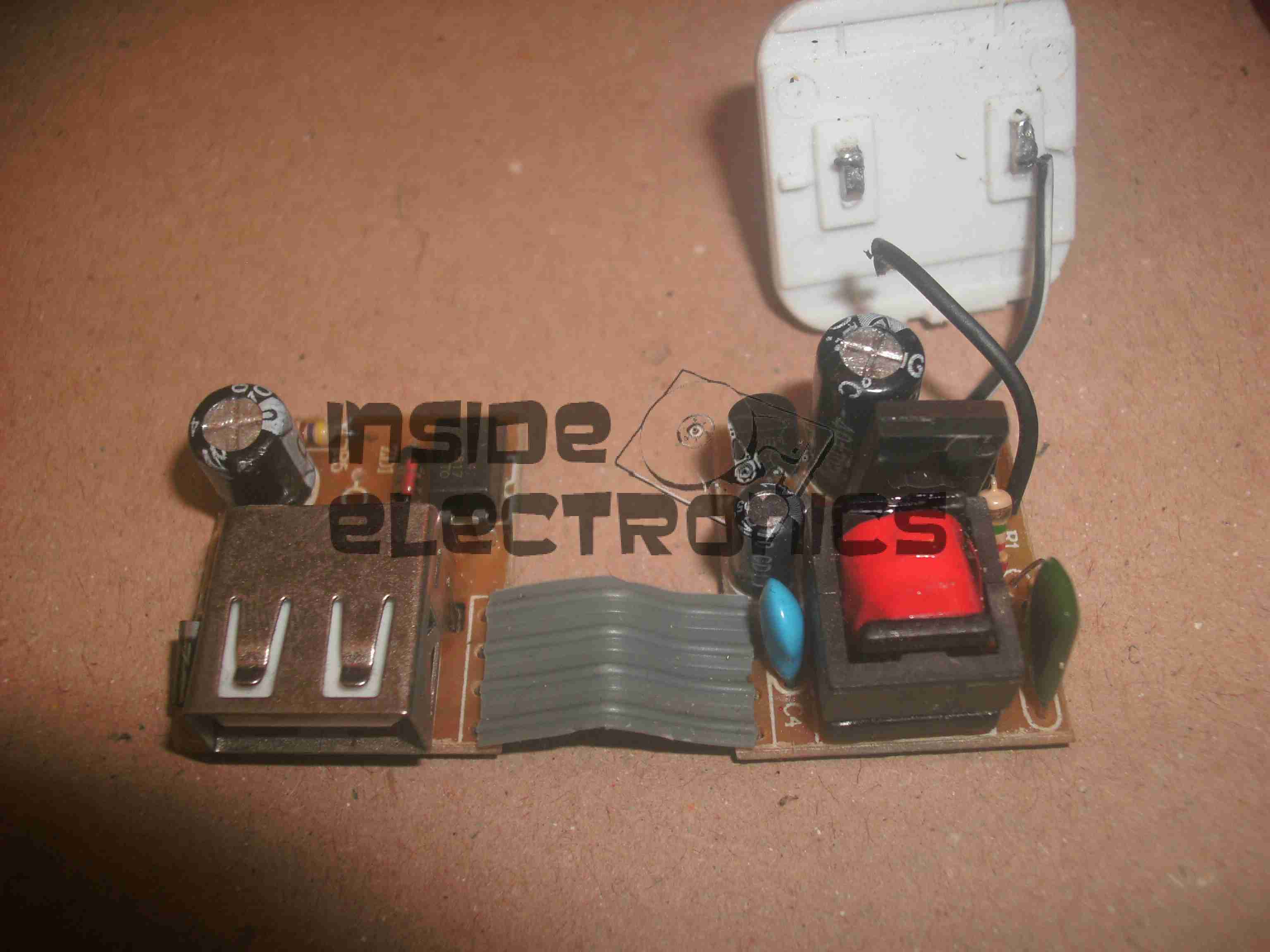
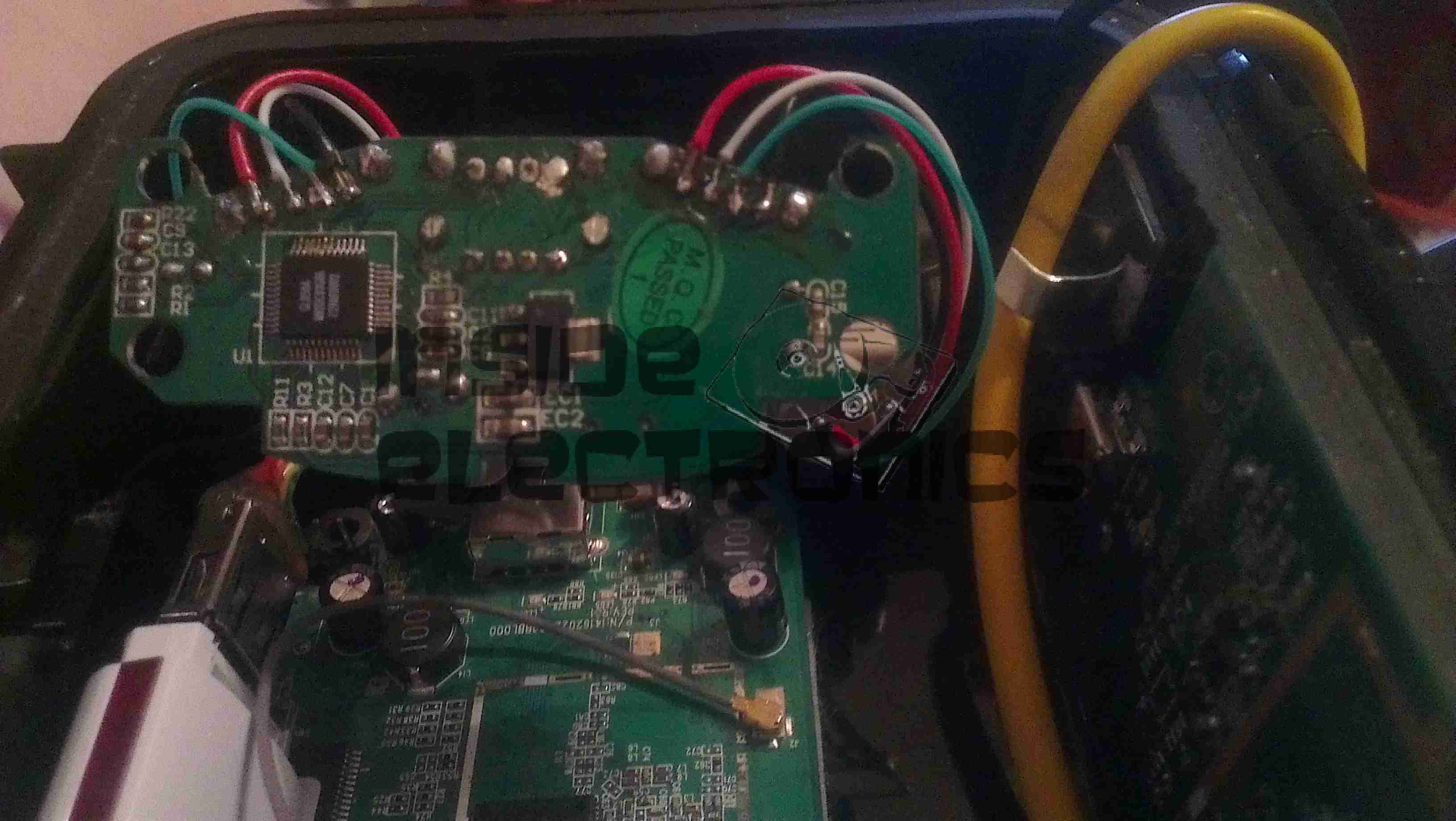
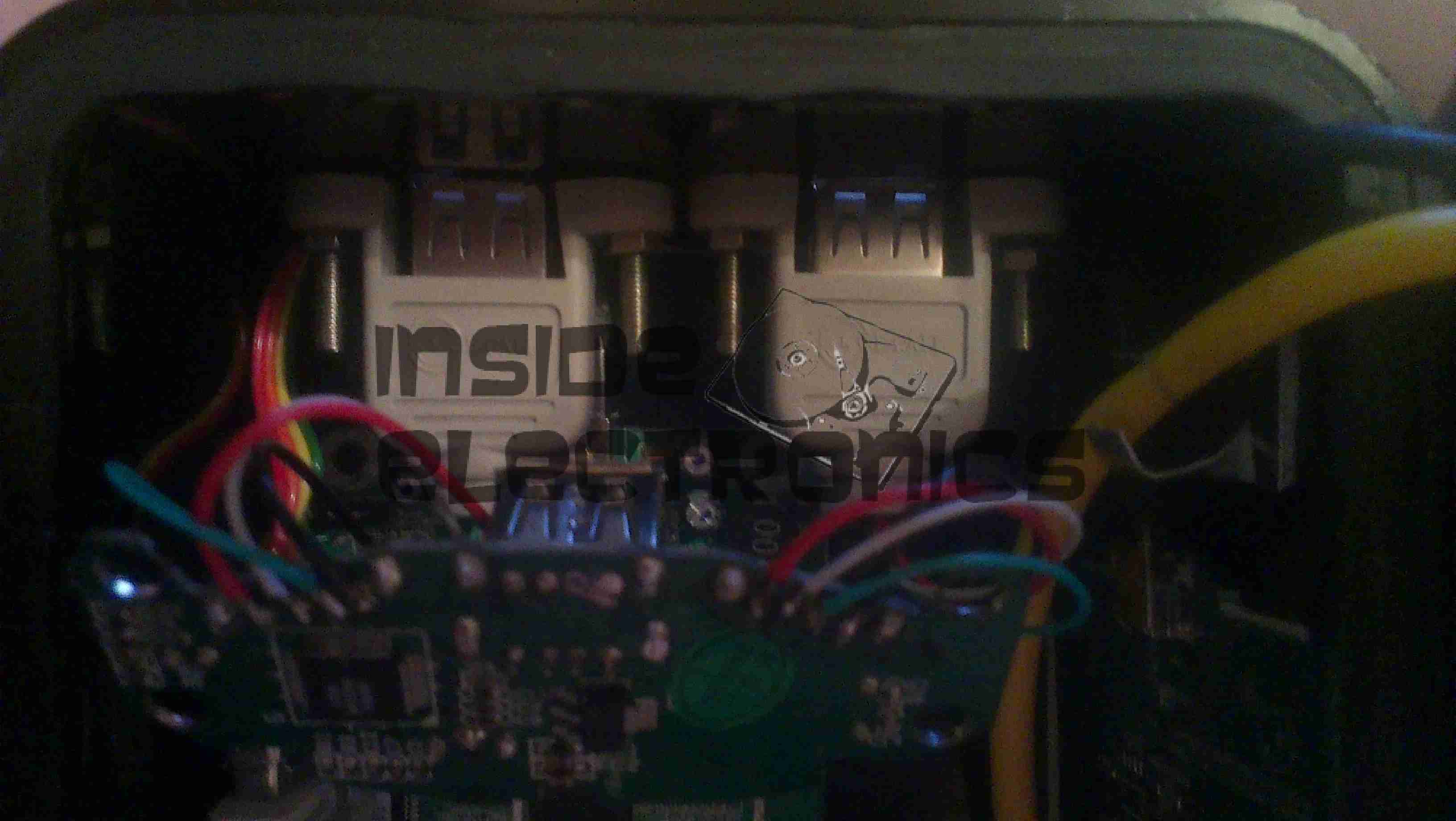
Here is the charger disassembled. Inside the case these two boards are folded together, creating an alarmingly small isolation gap between the mains side of the supply & the 5v output. Both the low voltage output & the feedback loop for the supply runs over the 4-core ribbon cable.
The mains wiring from the board is as thin as hair, insulation included, so there is a big possibility of shorts all over the place from this part of the circuit alone.

Bottom Of Boards
Bottom Of Boards

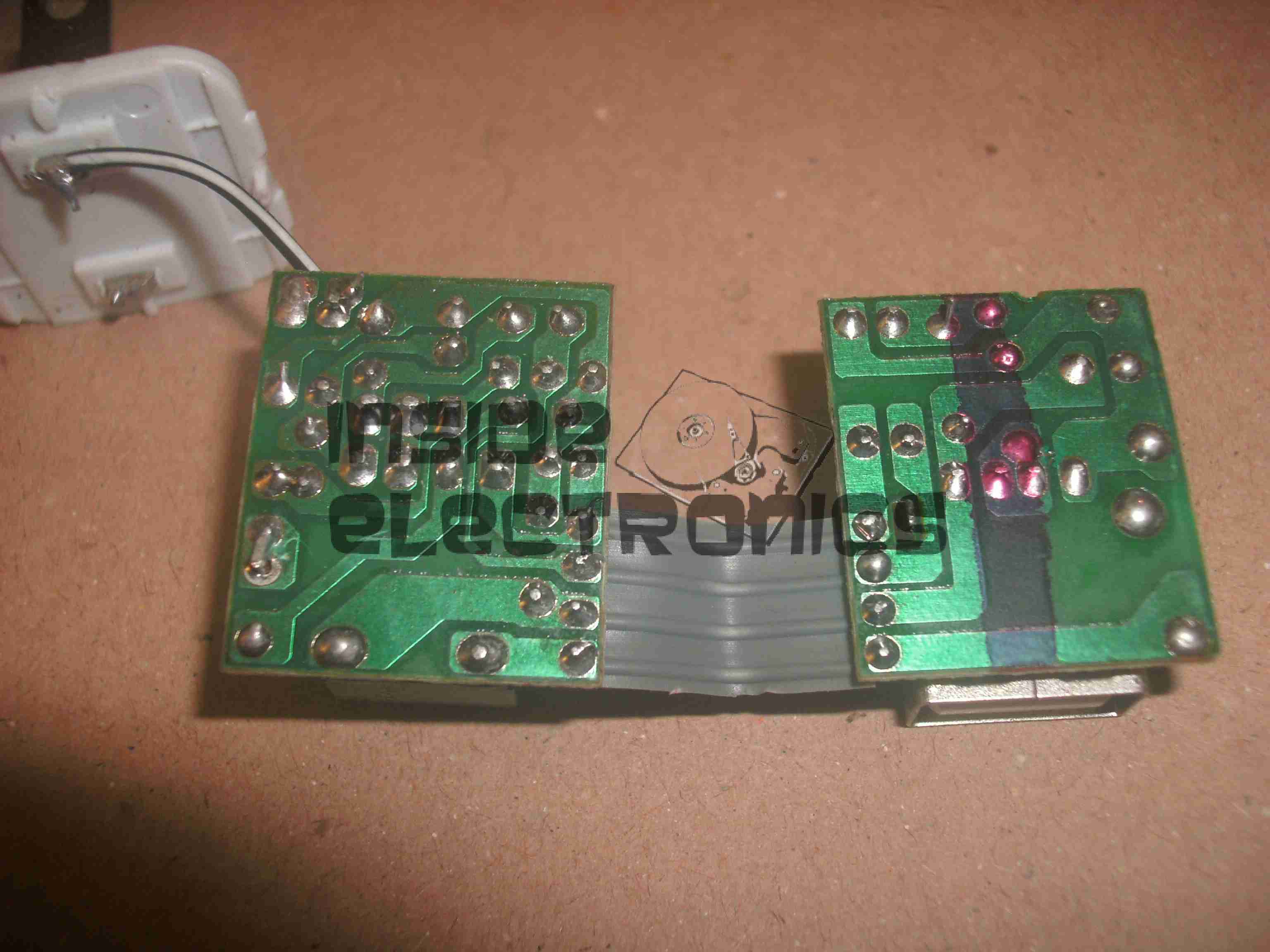
Bottom of the PCB assemblies. Good luck finding any creepage distance here. There simply isn’t any at all. traces on the +350v DC rail on the mains side of the transformer are no more than 1mm away from the supposedly isolated low voltage side.

Plugging one of these devices into anything is just asking for electrocution.


Posted on Leave a comment

Raspberry Pi Geiger Counter

Geiger Counter Setup

Here’s my latest project with the Pi: interfacing it with the Sparkfun Geiger counter & outputting the resulting data to a character LCD.

The geiger counter is interfaced with it’s USB port, with the random number generator firmware. A Python script reads from the serial port & every minute outputs CPM & µSv/h data to the display.

The Python code is a mash of a few different projects I found online, for different geiger counters & some of my own customisations & code to write the info to the display & convert CPM into µSv/h.

This also writes all the data into a file at /var/log/radlog.txt

The code for this is below:

import time
import sys
import serial
import os
import RPIO
from RPLCD import CharLCD
from subprocess import * 
from datetime import datetime

# configuration settings

logfile = "/var/log/radlog" # location to save log data
serial_port = "/dev/ttyUSB0"
lcd = CharLCD(pin_rs=15, pin_rw=18, pin_e=16, pins_data=[21, 22, 23, 24], numbering_mode=RPIO.BOARD, cols=16, rows=4, dotsize=10) #Init LCD with physical parameters

f = open(logfile,"a")

ser = serial.Serial(serial_port,9600,timeout=1)

one = 0

#Init LCD with initial values.
lcd.cursor_pos = (0, 1)
lcd.write_string("Geiger Counter")
lcd.cursor_pos = (1, 2)
lcd.write_string("Initializing")
lcd.cursor_pos = (2,-3)
lcd.write_string("Please Wait...")
lcd.cursor_pos = (3, 0)
lcd.write_string(str(0) +" uSv/h")
f.write("Geiger Counter Initialized\n")
f.flush()
while 1==1:
  stamp = int(time.time())
  stamp == round(stamp,0)
  stamp = stamp + 60
  count = 0  
  while 1==1:
      ct = int(time.time())
      ct == round(ct,0)
      if ct > stamp:  break
      #Read from serial port
      bit = ser.read(1)
      if bit != "":
          count = count + 1
          #Conversion of counts per minute to uSv/hr
          usvh = count * 0.01
  at = str(time.asctime())
  t = str(time.time())
  #Write line to log file & print info to console
  f.write("["+at+"."+t+"] "+str(count) + " CPM " +str(usvh) + " uSv/h\n")
  f.flush()
  print "["+at+"."+t+"] Count "+str(count) + " " + str(usvh) +" uSv/hr"
  #Send measurement info to LCD
  lcd.clear()
  lcd.cursor_pos = (0, 0)
  lcd.write_string(datetime.now().strftime('%b %d  %H:%M:%S\n'))
  lcd.cursor_pos = (1, 0)
  lcd.write_string("Radiation Level:")
  lcd.cursor_pos = (2, 1)
  lcd.write_string(str(count) +" CPM")
  lcd.cursor_pos = (3, -1)
  lcd.write_string(str(usvh) +" uSv/h")
Info Display
Info Display
Posted on Leave a comment

Wearable Raspberry Pi – Some Adjustments

USB Hub
USB Hub

As the first USB hub I was using was certainly not stable – it would not enumerate between boots & to get it working again would require waiting around 12 hours before applying power, it has been replaced. This is a cheapie eBay USB hub, of the type shown below.

These hubs are fantastic for hobbyists, as the connections for power & data are broken out on the internal PCB into a very convenient row of pads, perfect for integration into many projects.

Breakout Hub
Breakout Hub

I now have two internal spare USB ports, for the inbuilt keyboard/mouse receiver & the GPS receiver I plan to integrate into the build.

These hubs are also made in 7-port versions, however I am not sure if these have the same kind of breakout board internally. As they have the same cable layout, I would assume so.


Connector Panel
Connector Panel

Here is a closeup of the back of the connectors, showing a couple of additions.

I have added a pair of 470µF capacitors across the power rails, to further smooth out the ripple in the switching power supply, as I was having noise issues on the display.

Also, there is a new reset button added between the main interface connectors, which will be wired into the pair of pads that the Raspberry Pi has to reset the CPU.
This can be used as a power switch in the event the Pi is powered down when not in use & also to reset the unit if it becomes unresponsive.


Posted on Leave a comment

Wearable Raspberry Pi Part 1.75

USB Hub
USB Hub

The hub for the external USB ports has been fitted here, with the two ports hardwired to the pads where once there were USB A sockets. This hub will also accommodate the wireless receiver for the mini keyboard & mouse, in the remaining port that will sit between the external USB ports.

USB Ports
USB Ports

In this gap between the ports is where the wireless receiver will sit for the keyboard & mouse, the pair of screws securing the external ports in the centre have been shortened to make more room.

Posted on Leave a comment

Wearable Raspberry Pi Part 1.5

USB Ports
USB Ports

For convenience, a pair of USB ports have been fitted to the wearable Pi, which open on the bottom of the unit. These will be hardwired into a 4-port USB hub which will also support the wireless adaptor for the mini-keyboard that is to be used with the device.

USBs
USBs

The two USB ports on the bottom of the casing.

External Connections

The external connectors are also complete. The audio jack & second WiFi antenna port are fitted.

The audio is normally routed to the LCD display speaker, until a jack is plugged into the 3.5mm socket.


Posted on 3 Comments

Wearable Raspberry Pi Part 1

Overview
Overview

Here is the project I’m currently working on. A completely wearable computing platform based on the Raspberry Pi & the WiFi Pineapple.

Above can be seen the general overview of the current unit.

On the left:

  • Alfa AWUS036NHA USB High Power WiFi Network Interface
  • 512MB Model B Raspberry Pi, 16GB SD card, running Raspbian & LXDE Desktop. Overclocked to 1GHz.

On the right:

  • WiFi Pineapple router board
  • USB 3G card.

The WiFi, Pineapple & 3G all have external antenna connections for a better signal & the whole unit locks onto the belt with a pair of clips.
The Raspberry Pi is using the composite video output to the 7″ LCD I am using, running at a resolution of 640×480. This gives a decent amount of desktop space while retaining readability of the display.

The case itself is a Pelican 1050 hard case, with it’s rubber lining removed. The belt clips are also a custom addition.

Connections
Connections

Here are the connections to the main unit, on the left is the main power connector, supplying +5v & +12v DC. The plug on the right is an 8-pin connection that carries two channels of video, mono audio & +12v power to the display.
Currently the only antenna fitted is the 3G.

Connectors
Connectors

Closeup of the connections for power, audio & video. The toggle switch is redundant & will soon be replaced with a 3.5mm stereo jack for headphones, as an alternative to the mono audio built into the display.

Test Run
Test Run

Current state of test. Here the unit is running, provided with an internet connection through the Pineapple’s 3G radio, funneled into the Pi via it’s ethernet connection.

Pi Goodness!
Pi Goodness!

Running on a car reversing camera monitor at 640×480 resolution. This works fairly well for the size of the monitor & the text is still large enough to be readable.


Stay tuned for Part 2 where I will build the power supply unit.


Posted on Leave a comment

Media PC Build Log

Front
Front

This will be the record of building a new Media PC, above you can see the finished system.

It’s Mini-ITX based, with on-board HDMI output, specifically to run XBMC via Fedora for media purposes.

CiC MTX001B Mini-ITX Case

This is the case that is being used, around the size of a Shuttle PC. It has a single 3.5″ & 5 1/4″ bay, for a HDD & ODD, front panel USB, Firewire & Audio.

Intel BLKDH57JG Mini-ITX Motherboard

Motherboard to fit the case. Supports Intel Core i5 series CPUs, with up to 8GB of DDR3 RAM.
Other features are on-board full surround audio, HDMI, eSATA, & a single 16x PCIe slot.

Corsair 4GB DDR3 DIMMs

Matching memory for the motherboard, a pair of 4GB DDR3 units.

Akasa K25 Low Profile CPU Cooler

Having never been impressed by bundled coolers with CPUs, here is an aftermarket low-profile unit, with solid copper core for enhanced cooling. This cooler is specially designed for Mini-ITX uses.

Intel Core i5 650 Dual Core 3.2GHz CPU

The brains of the operation, Core i5 650 CPU, should handle HD video well.

Posted on Leave a comment

New Feature – Geiger Counter

Here’s something new, an internet connected Geiger counter! The graph in the sidebar is updated once every 60 seconds, and can be clicked on for a larger version. Measurements are in Counts Per Minute, the graph logs 1 hour of data.


The counter itself is a Sparkfun Geiger counter, with the end cap removed from the tube so it can also detect alpha radiation.

Connected through USB, a Perl script queries the emulated serial port for the random 1 or 0 outputted by the counter when it detects a particle. The graph is pretty basic, but it gets the point across. Anybody who wishes to contribute to improve the graphing is welcome to comment!

Geiger Counter
Geiger Counter
Posted on Leave a comment

ShowWX+ Pico Projector First Light

Projection
Projection

Above is the image projected from the Pi, on the default login screen. Distance from the projector is approx 10 feet.

Projector
Projector

State of the art projector mount, fashioned from several cable ties. HDMI cable is plugged into the right hand side of the projector.

Unfortunately the projector cannot handle audio on the HDMI connector, the 3.5mm headphone jack on the projector is for splitting audio out of the iDevice connection only, and does not make the HDMI audio stream available.


Pi
Pi

The Raspberry Pi, hosting a USB keyboard, & USB powered speakers. Running the standard Debian release, on a 16GB card, with omxplayer installed for media functions.

Posted on 1 Comment

MSR605 3-Track Magnetic Stripe Writer

MSR605
MSR605

This unit was bought from eBay to experiment with Magnetic Stripe cards, for little money. This unit is capable of reading & writing all 3 tracks, & both Hi-Co & Lo-Co card types.
Interfaced to a PC through USB, this has a built in PL2303 USB-Serial IC & requires 3A at 9v DC to operate.
The 3 Indicator LEDs on the top of the unit can be toggled by the included software for Power/OK/Fault condition signalling.

Unit Bottom
Unit Bottom

Bottom of the unit with the model labels.

Model Label
Model Label

Closeup of the model label & serial number.

PCB Bottom
PCB Bottom

Here the bottom cover has been removed, showing the main PCB. The pair of large ICs bottom center interface with the magnetic heads. The IC above them has had the markings sanded off.

USB-Serial Interface

Closeup of the Prolific PL-2303 USB-Serial converter IC.

PCB Top
PCB Top

Here the connections to the R/W heads are visible, current limiting resistors at the left for the write head, a pair of signal relays, a pair of optoisolators & a LM7805 linear voltage regulator.

LEDs
LEDs

Here is the trio of indicator LEDs on a small sub-board.

Frame Bottom
Frame Bottom

The PCB has been removed from the main frame here, the only component visible is the rotary encoder.

Rotary Encoder
Rotary Encoder

The rotary encoder has a rubber wheel fitted, which reads the speed of the card as it is being swiped for writing. This allows the control logic to write the data to the stripe at the correct rate for the speed of the card. This allows the unit to write cards from 5-50 inches per second speed.
The Write head is directly behind the rubber pressure roller.

Read/Write Heads
Read/Write Heads

Here you can see the R/W head assembly. The write head is on the right, read on the left. When a card is written to, it immediately gets read by the second head for verification.

The drivers for this unit are also available here: Magcard Writer Drivers

Posted on Leave a comment

Sigma Mini Keychain LCD Photoframe

Front
Front

This is a cheap Sigma branded keychain photoframe. User buttons for power & selecting photos are on the left.
There are two white LEDs on the bottom edge that function as a torch as well.

Display
Display

Front of the unit removed, showing the LCD module. The USB jack is bottom left, next to the pair of white LEDs & above that is the 32kHz watch crystal that the CPU uses for timekeeping.

Back Removed
Back Removed

Here the back has been removed showing the 3.7v Li-Ion cell used to provide power.

Display Folded Back
Display Folded Back

Here the display has been removed from the PCB exposing the chipset.

Chipset
Chipset

Here the CPU blob-top chip & a flash memory IC are visible. The CPU is a Sitronix ST2205U.

Posted on Leave a comment

USB Multi Card Reader

Card Reader
Card Reader

Here is a cheap USB 8-in-1 card reader. Power & Access LEDs are on top left.

PCB Top
PCB Top

Top of the PCB. The OTi IC is the interface IC to the USB port, part number is OTI002126. Card sockets on the top here are CF/Microdrive & Memory Stick.

PCB Bottom
PCB Bottom

Bottom of the PCB with the SD/MMC, Smart Media

Posted on Leave a comment

USB-IDE/SATA Adaptor

Front
Front

This is a device to use an IDE or SATA interface drive via a USB connection. Here is the front of the device, IDE interface at the bottom, 2.5″ form factor.

PCB Top
PCB Top

PCB removed from the casing. USB cable exits the top, 12v DC power jack to the left.
SATA interface below the DC Jack.
Molex connector below SATA is the power output for the drive in use. This unit has a built in 5v regulator.

PCB Bottom
PCB Bottom

Bottom of the PCB showing the interface IC.

Drive Adaptor
Drive Adaptor

Adaptor to plug into the 44-pin 2.5″ form factor IDE interface on the adaptor, converts to standard 40-pin 3.5″ IDE.

Power Cable
Power Cable

Power pigtail with standard Molex & SATA power plugs.

Posted on Leave a comment

Grand Hand View

Front
Front

This is an adaptor to convert computer VGA to composite & S-Video output for a normal TV.

Bottom
Bottom

Bottom of the unit with option select switch.

PCB Top
PCB Top

PCB removed from the casing, CPU in centre, buffer RAM on the right.

PCB Bottom
PCB Bottom

Reverse side with the VGA connections at the top & the S-Video/composite outputs on the bottom.

VGA
VGA

Inputs. USB connector provides power, pair of VGA connectors provides passthrough function.

S-Video & Composite
S-Video & Composite

Outputs. Standard S-Video on the left & composite video on the right.

Posted on 1 Comment

Hauppauge WinTV USB

Front
Front

Here is one of the first USB tuners that was available from Hauppauge Computer Works. Totally analog tuner of course, this model required 2 cables – a USB interface & a sound cable for the audio output of the tuner.

I/O
I/O

A/V connections.

Label
Label

For those who are interested. Here is the label with the model details.

Antenna Connection
Antenna Connection

Connection to an external antenna.

PCB Bottom
PCB Bottom

Bottom of the PCB.

PCB Top
PCB Top

Top of the PCB showing the USB interface IC (top left), cache memory (top right) & the main tuner assembly.

Posted on Leave a comment

Power Pack Regulator Update

7.5v Regulator
7.5v Regulator

To help make my system more efficient, a pair of switching regulators has been fitted, the one shown above is a Texas Instruments PTN78060 switchmode regulator module, which provides a 7.5v rail from the main 12v battery pack.

A Lot like the LM317 & similar linear regulators, these modules require a single program resistor to set the output voltage, but are much more efficient, around the 94% mark at the settings used here.

The 7.5v rail supplies the LM317 constant current circuit in the laser diode driver subsection. This increases efficiency by taking some voltage drop away from the LM317.

5v Regulator
5v Regulator

The 7.5v rail also provides power to this Texas Instruments  PTH08000 switchmode regulator module, providing the 5v rail for the USB port power.

Posted on Leave a comment

Portable Power Supply

Battery
Battery

This is detailing my portable multi-purpose power pack of my own design. Here is an overview, mainly showing the 4Ah 12v Ni-Cd battery pack.

Front Panel Right
Front Panel Right

Panel Features – Bottom: Car cigar lighter socket, main power keyswitch. Top: LED toggle switch, provision for upcoming laser project, Red main Power LED, 7A circuit breaker.

Front Panel Left
Front Panel Left

Top: Toggle switch serving post terminals, USB Port.
Post terminals supply unregulated 12v for external gadgets. USB port is standard 5v regulated for charging phones, PDAs etc.
Bottom: Pair of XLR connectors for external LED lights. Switches on their right control power & the knob controls brightness.

Additions are being made to this all the time, the latest being a 2W laser diode driver. Update to come soon!

Posted on Leave a comment

Belkin F5U021 4-Port USB Hub

Top
Top

This is an old USB 1.1 hub that was recently retired from service on some servers. Top of the unit visible here.

Bottom Label
Bottom Label

Bottom label shows that this is a model F5U021 hub, a rather old unit.

PCB Front
PCB Front

PCB is here removed from the casing, Indicator LEDs along the bottom edge of the board, power supply is on the left. Connectors on the top edge are external power, USB host, & the 4 USB outputs. Yellow devices are polyswitch fuses for the 500mA at 5v each port must supply.

USB Hub IC
USB Hub IC

This is the USB Hub Controller IC, which is a Texas Instruments TUSB2046B device. Power filter capacitors next to the USB ports are visible here also, along with 2 of the polyswitches.

Power Supply
Power Supply

The power supply section of the unit, which supplies regulated 5v to the ports, while supplying regulated 3.3v to the hub controller IC. Large TO-220 IC is the 5v regulator. Smaller IC just under the power selector switch is the 3.3v regulator for the hub IC. The switch selects between Host powered or external power for the hub.

Posted on Leave a comment

USB Flash Drive

Disk
Disk

Here is a cheap chinese made flash drive given out for free by Westlaw UK. Capacity 512MB

PCB
PCB

Here is the PCB removed from the casing, USB connector on the left, followed by the clock crystal for the flash controller, a CBM2092, which is a Chipsbank part. 512MB flash memory IC, unknown maker.  Access LED on far right of the board.

Posted on Leave a comment

Motorola V360v

Front
Front

Here is a more modern phone, the Motorola V360v. Features include Dual screens, 640×480 VGA camera, full col

our TFT Main LCD, SD-Micro slot.
Here on the back the grey scale LCD can be seen, with the camera lens to the right of the Motorola logo

Keypad
Keypad

Here the phone is opened showing the keypad & the full colour TFT LCD display.

Battery Compartment
Battery Compartment

Here the battery is removed from the unit, showing the SIM connector. The antenna cover is still on at the bottom.

Antenna
Antenna

The antenna cover has been removed in this shot, the antenna is the white section at the bottom, With the loudspeaker & the external antenna connector hidden at the right.

PCB
PCB

Here is the main PCB. Parts from left are the Bluetooth module at the top, supplied by Broadcom, the SD Card socket at the bottom. Main CPU next to that is the Freescale SC29343VKP. Above right of the CPU is the Freescale SC13890P23A Charger, Power & Audio IC. Below is the SIM card socket. Under the main CPU is the Intel Flash memory IC. ICs inside the shields are the RF sections for transmit & receive.

Cover Removed
Cover Removed

Rear of the display unit showing the monochrome LCD. The camera module on the bottom left. Ear speaker on the far right of the unit.

Main LCD
Main LCD

Main colour TFT LCD.

Camera
Camera

Camera module removed from the LCD unit.

Vibra-Motor
Vibra-Motor

The vibration motor attached to one of the LCD looms.

Posted on Leave a comment

HP Photosmart 375

Top
Top

This is a HP PhotoSmart 375 portable photo printer. With built in card reader, screen & PictBridge.
Top of the printer showing the UI Buttons & Screen.

Front
Front

Front of the unit, card reader slots at the top, Pictbridge USB connector at top left. Paper out slot at bottom. Cartridge door is on the right.

Cartridge Door
Cartridge Door

Here the cartridge door is open. Takes HP 95 Tri-Colour Inkjet Cartridge.

Battery Compartment
Battery Compartment

Battery compartment on the bottom of the unit. A Li-Ion battery pack can be installed here for mobile photo printing.

Bottom Label
Bottom Label

Specifications label.

USB + Power
USB + Power

Power adaptor & USB connection for PC use.

Paper Tray
Paper Tray

Rear door opened. Showing the paper feed tray.

Paper Feeder
Paper Feeder

Rear door has been removed in this shot. Paper feed roller & platen roller can be seen here.

Rear Cover Paper Feeder

Paper holder attached to rear door.

Top Cover
Top Cover

Bottom of the top cover, with connections for the buttons & LCD panel.

Main PCB
Main PCB

This is the main PCB of the unit. Controls all aspects of the printer. CPU in center, card reader sockets are along bottom edge. various support circuitry surrounds the CPU.

Rear
Rear

Rear shell has been removed here. Showing the main frame & the carriage drive motor on the left.

Carriage Drive
Carriage Drive

Closeup of the carriage drive motor & timing belt system. All the motors in this printer are DC servo motors, not steppers.

Main Drive Motor
Main Drive Motor

Main drive motor, feeds paper, drives rollers, operates cleaning mechanism for the inkjets.

Shaft Encoder
Shaft Encoder

Mainshaft encoder. Main drive motor is bottom right hand side with timing belt drive.

CPU
CPU

Closeup of the CPU. This is a Phillips ARM chip, unknown spec.

Card Reader Sockets
Card Reader Sockets

Detail of the card reader sockets, this unit takes all current types of Flash memory card.

HP 95 Tri-color Inkjet Print Cartridge