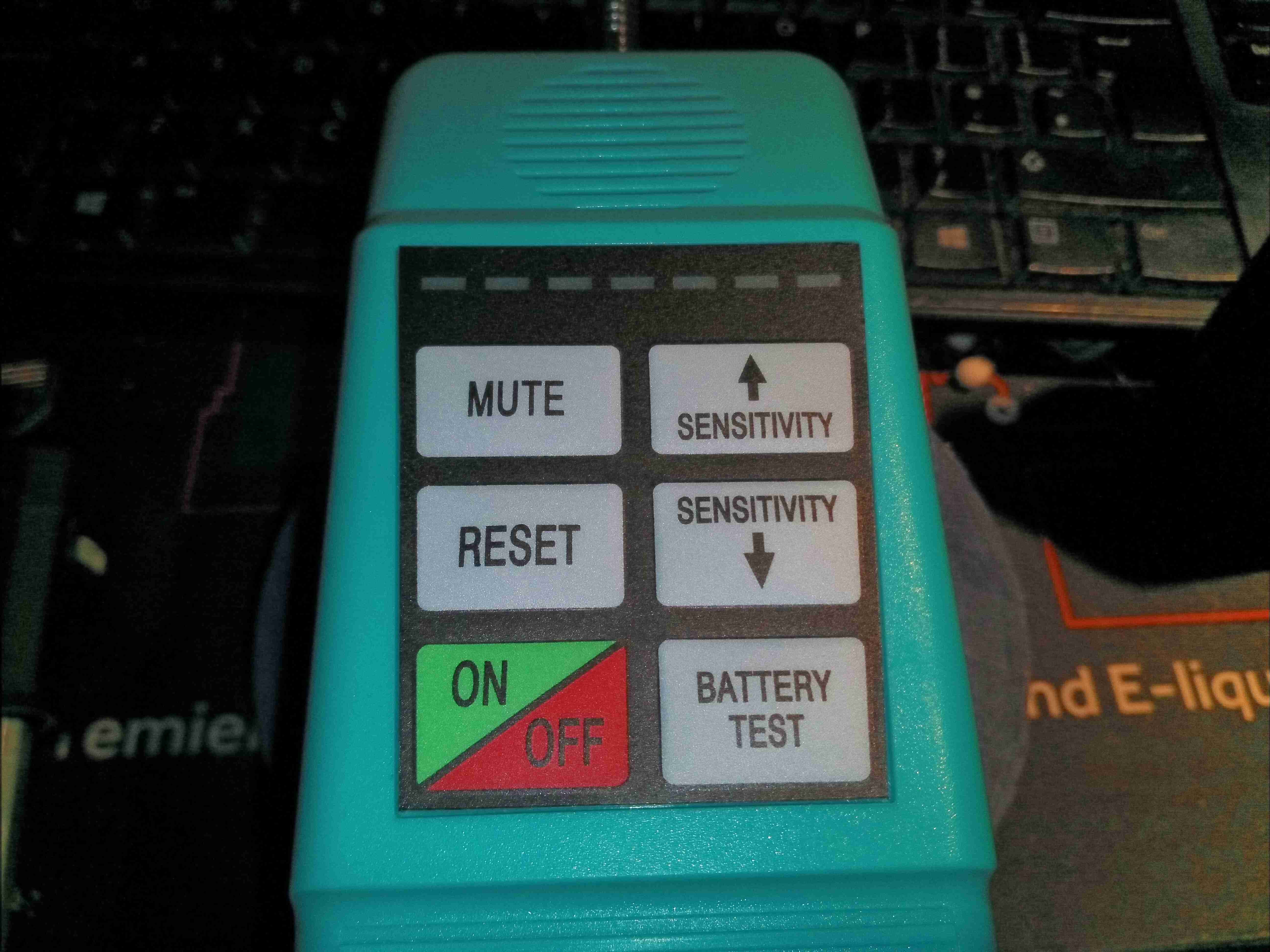
Here’s a useful device, for detecting leaks in refrigerant systems. These units use a high-voltage ionisation detection method using a probe at the tip with a sharp needle, similar to an ioniser to detect changes in conductivity of the surrounding gas.
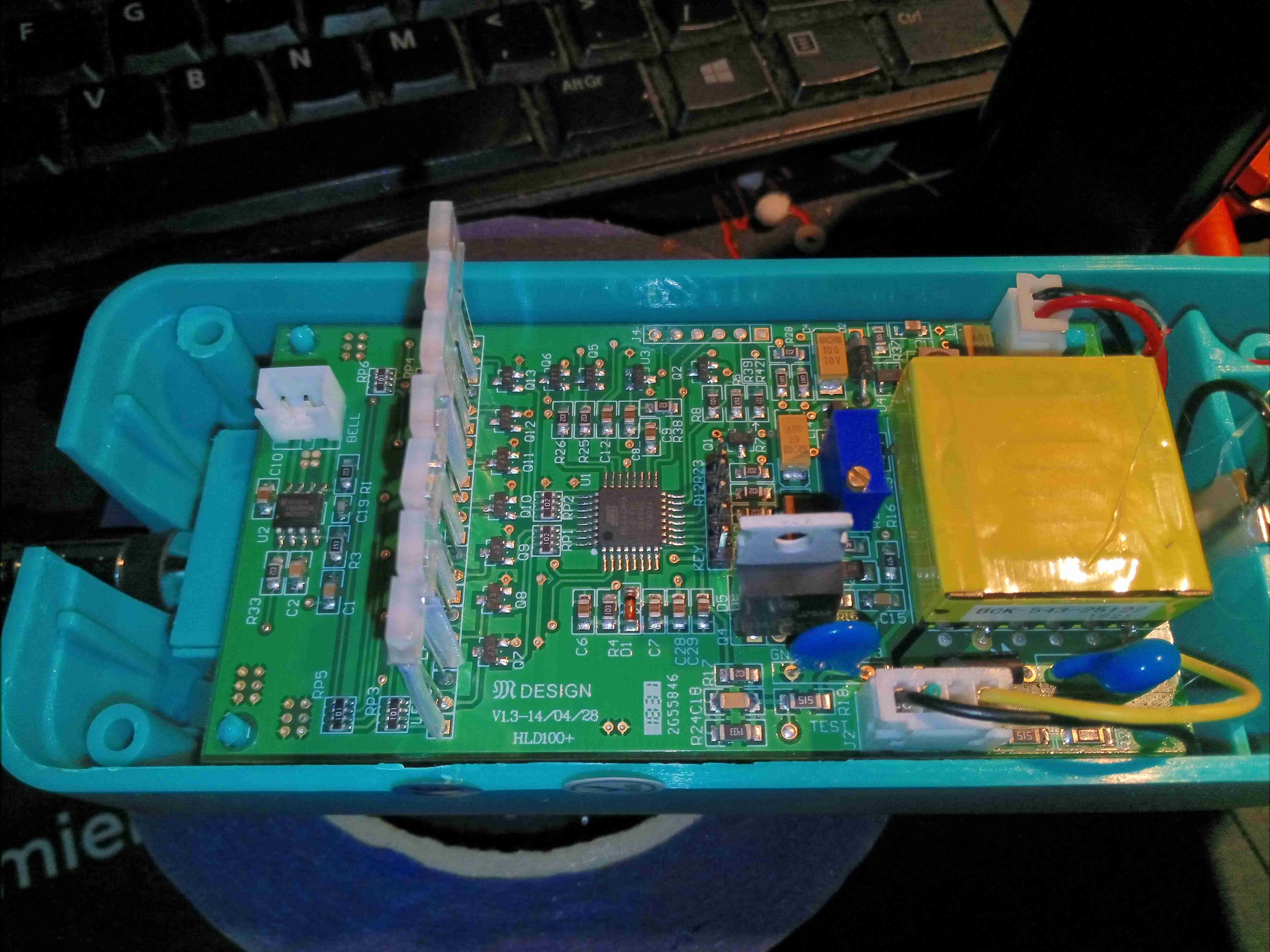
Removing the front case of the unit reveals the PCB, with it’s row of indicator LEDs on the top. The high voltage transformer is on the right, with it’s switching transistor. The probe swan neck is on the left.
The PCB is fairly heavily populated, and all a single-sided load, no doubt to reduce manufacturing costs. The main power input from the battery is on the bottom left, with a small switching regulator to the right supplying power to the control logic & microcontroller. There’s a multi-turn potentiometer, probably for adjusting the output voltage of the HT section. The header in the centre of the board is the connection point of the membrane keypad on the front of the unit.
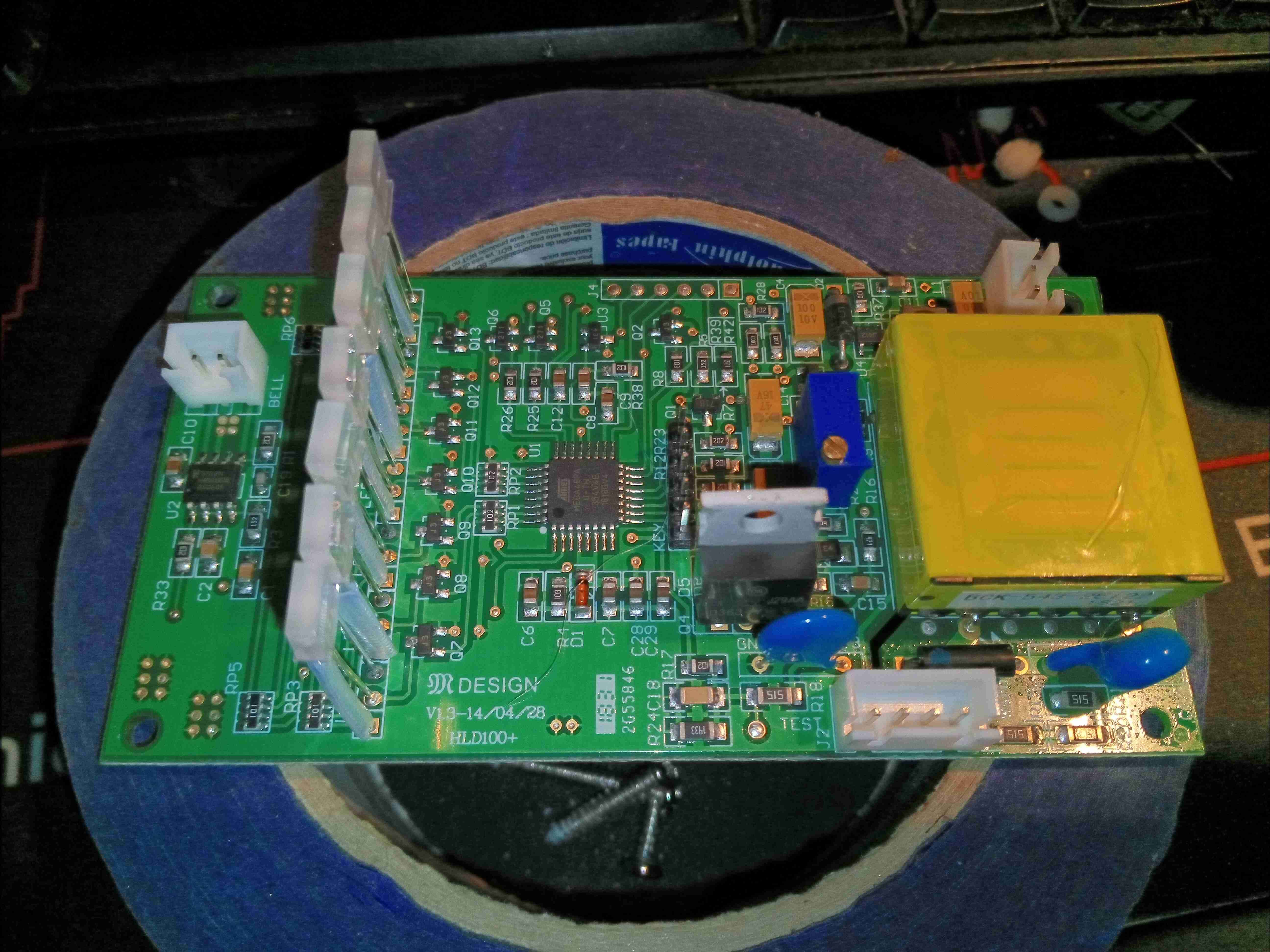
Not much more to see on the left side of the board, there’s the connection for the buzzer far left, and the main switching MOSFET for the high voltage transformer in the centre. The high voltage output is on a JST connector bottom right! I suspect the HV converter is fully under the control of the microcontroller in this unit, as there doesn’t appear to be any other control function present.
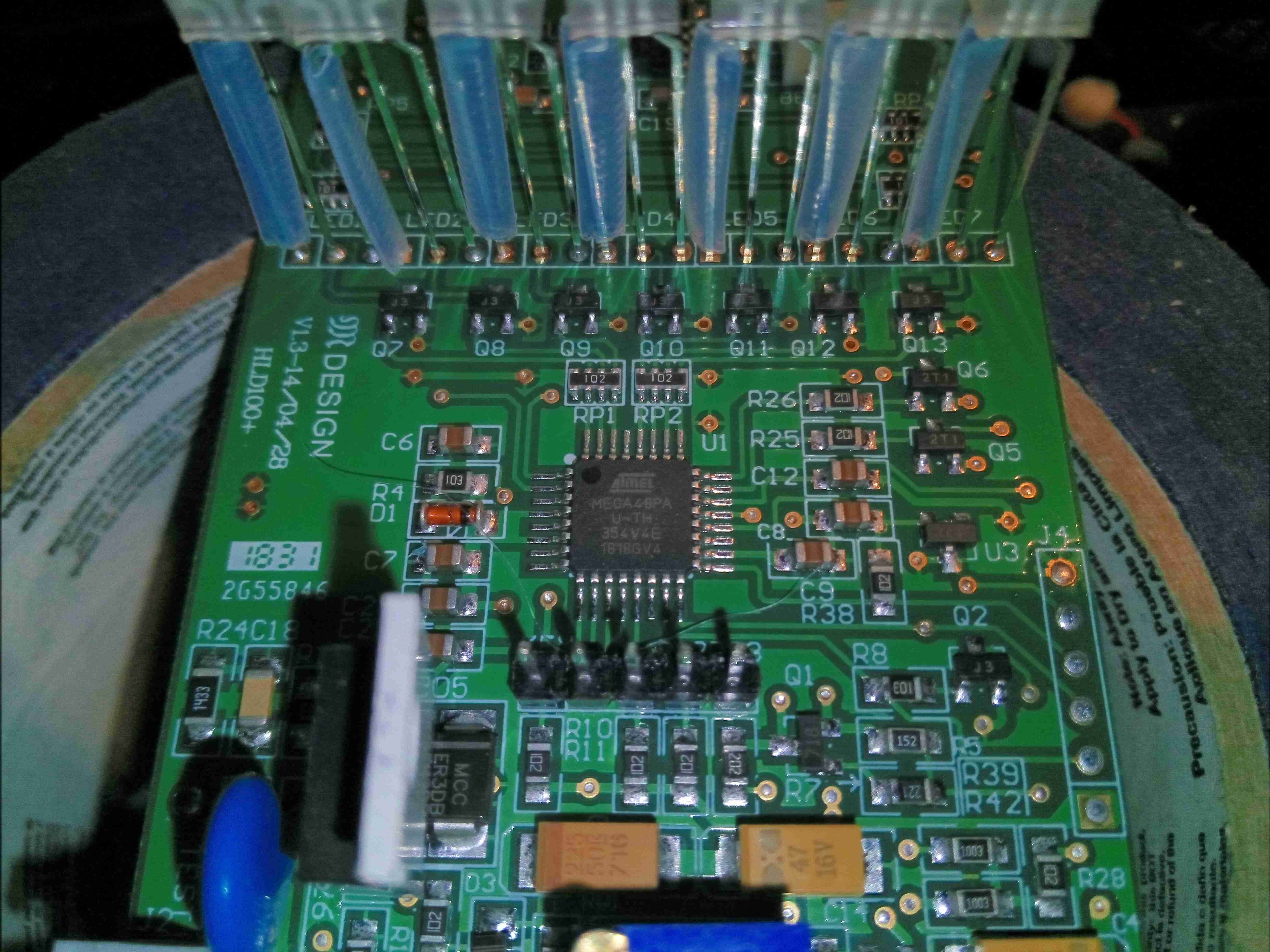
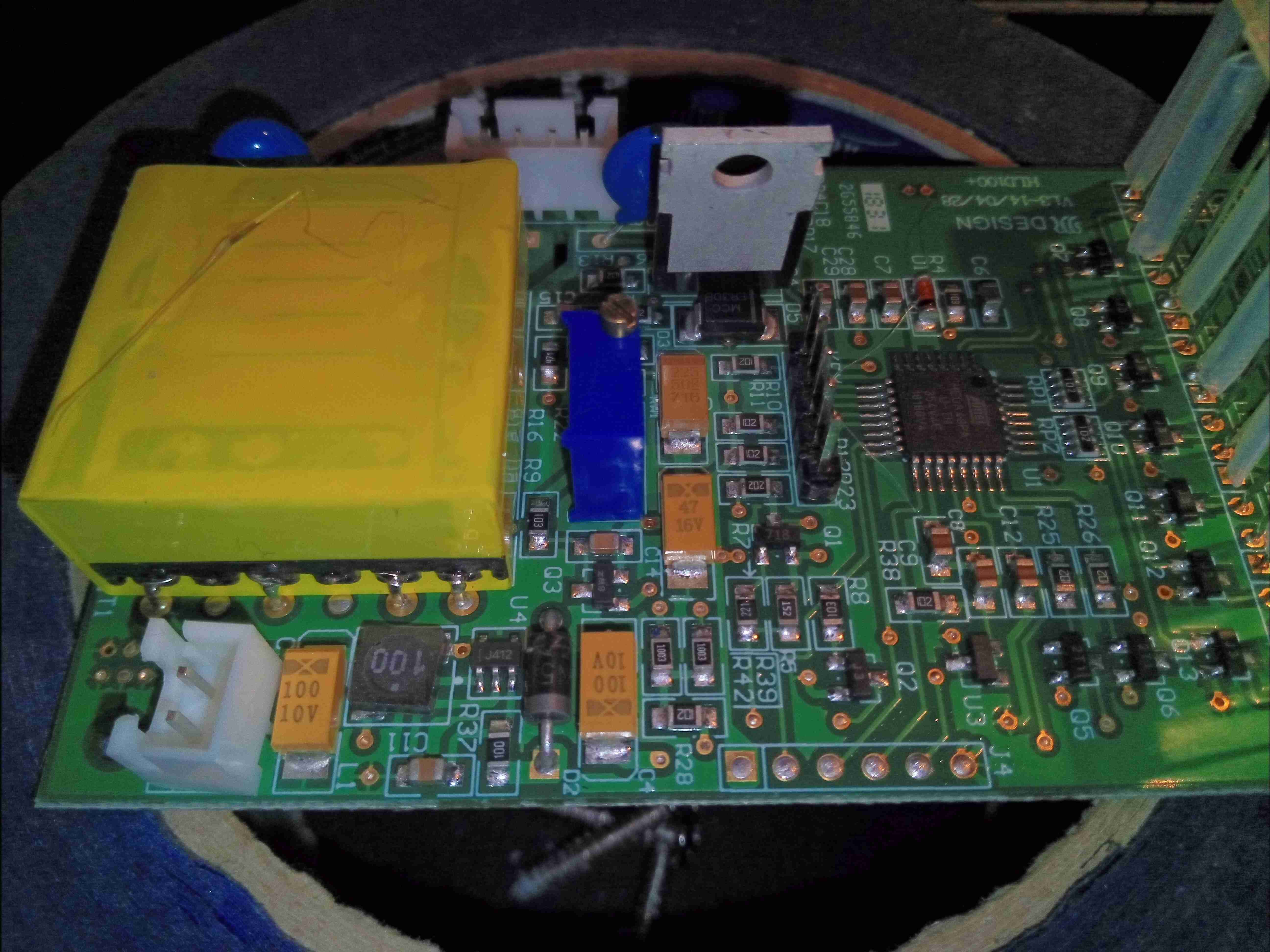
The main microcontroller is an ATMEGA48, with it’s programming header on the far right of the board.
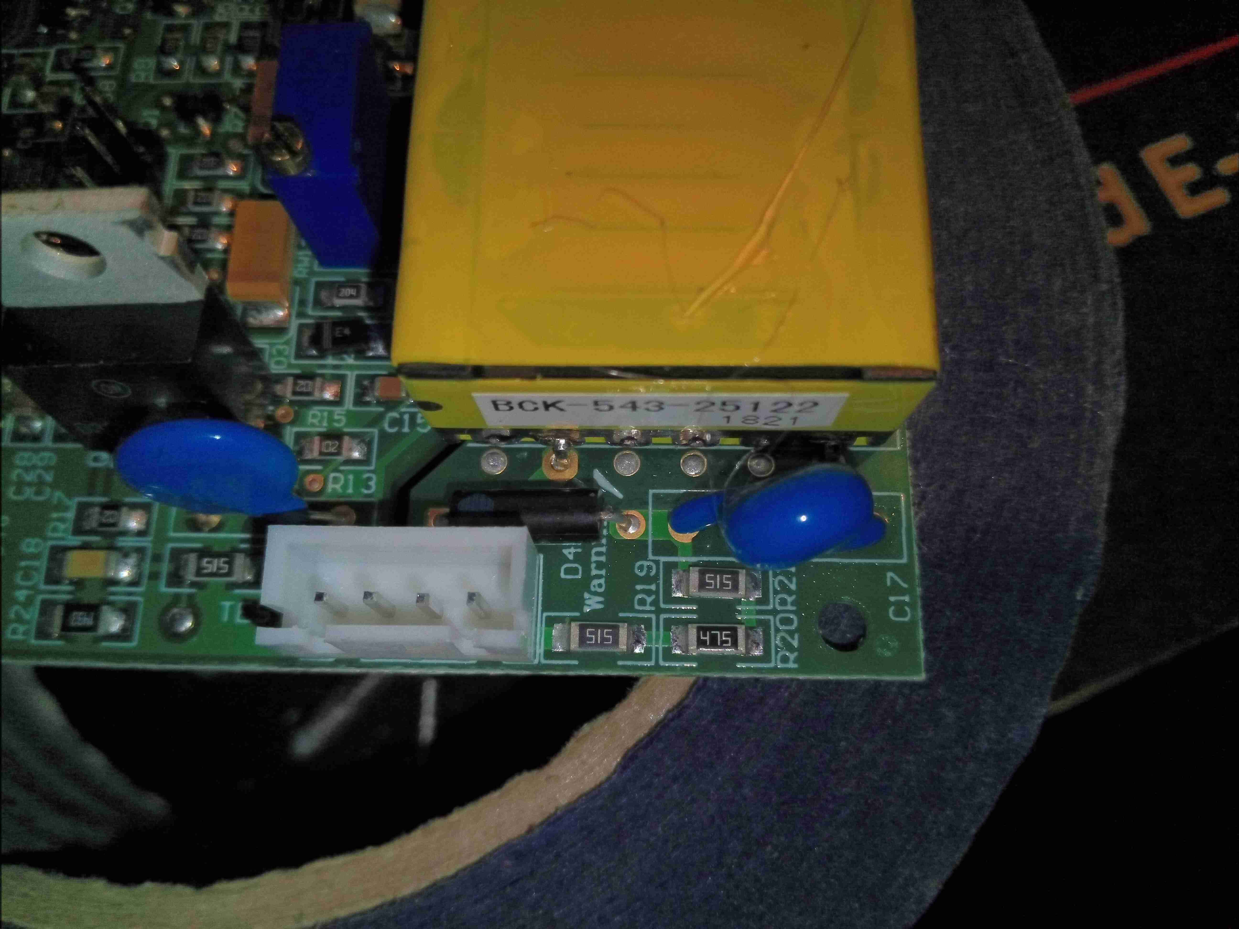
Finally, there’s the high voltage output section of the board with a couple of anti-tracking slots to prevent flashover. There’s a rectification diode, in half wave, a small smoothing capacitor before the string of current limiting resistors on the output of the unit to the probe. I haven’t been able to work out where the microcontroller is actually getting the gas conductivity measurement from – it may be measuring the input current drawn by the HV converter or it may be measuring the output current via one of the current-limiting resistors on the HV output.
