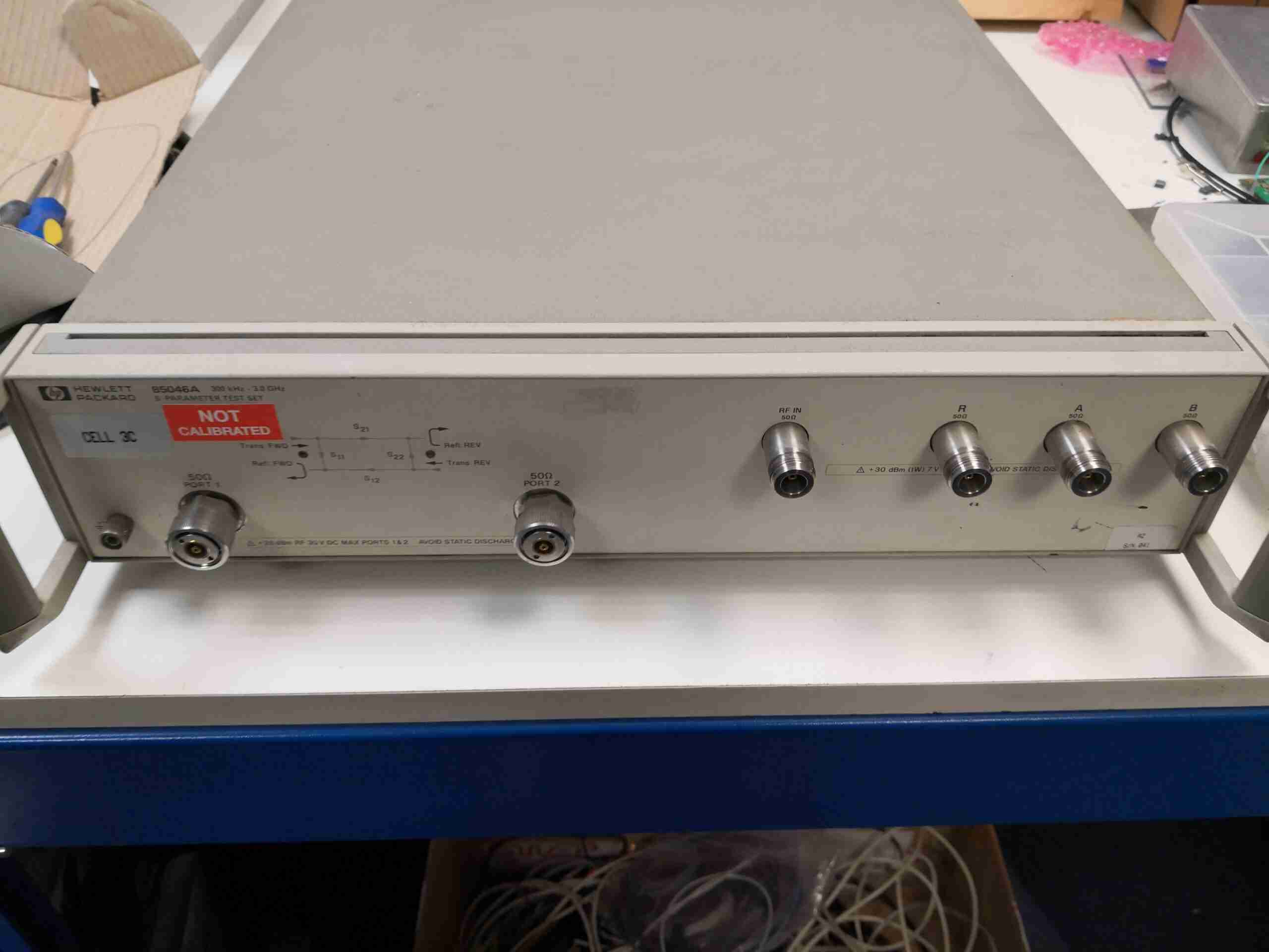
This enormous box is the S-Parameter Test Set from a HP 8753C 3GHz network analyser. This unit contains the required components to automate the testing process for items such as cables, antennas & RF networks.
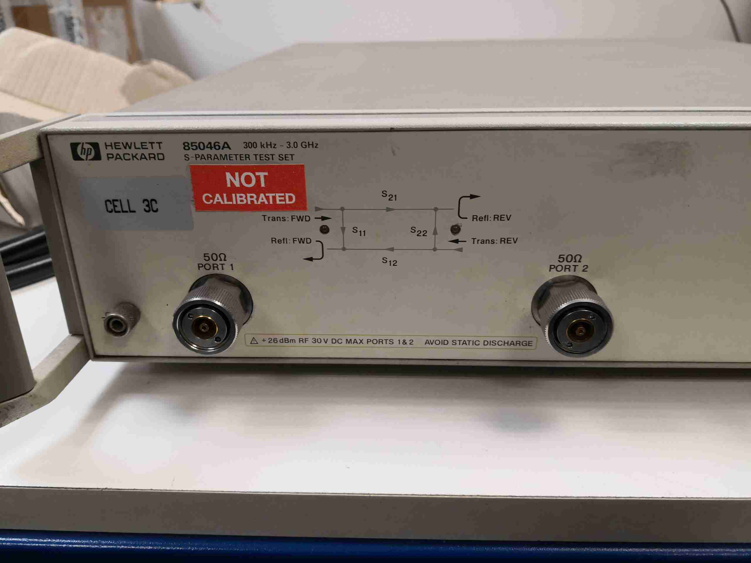
The main EUT test ports are APC-7mm type connectors – a very expensive genderless RF connector that provides very repeatable coaxial connections.
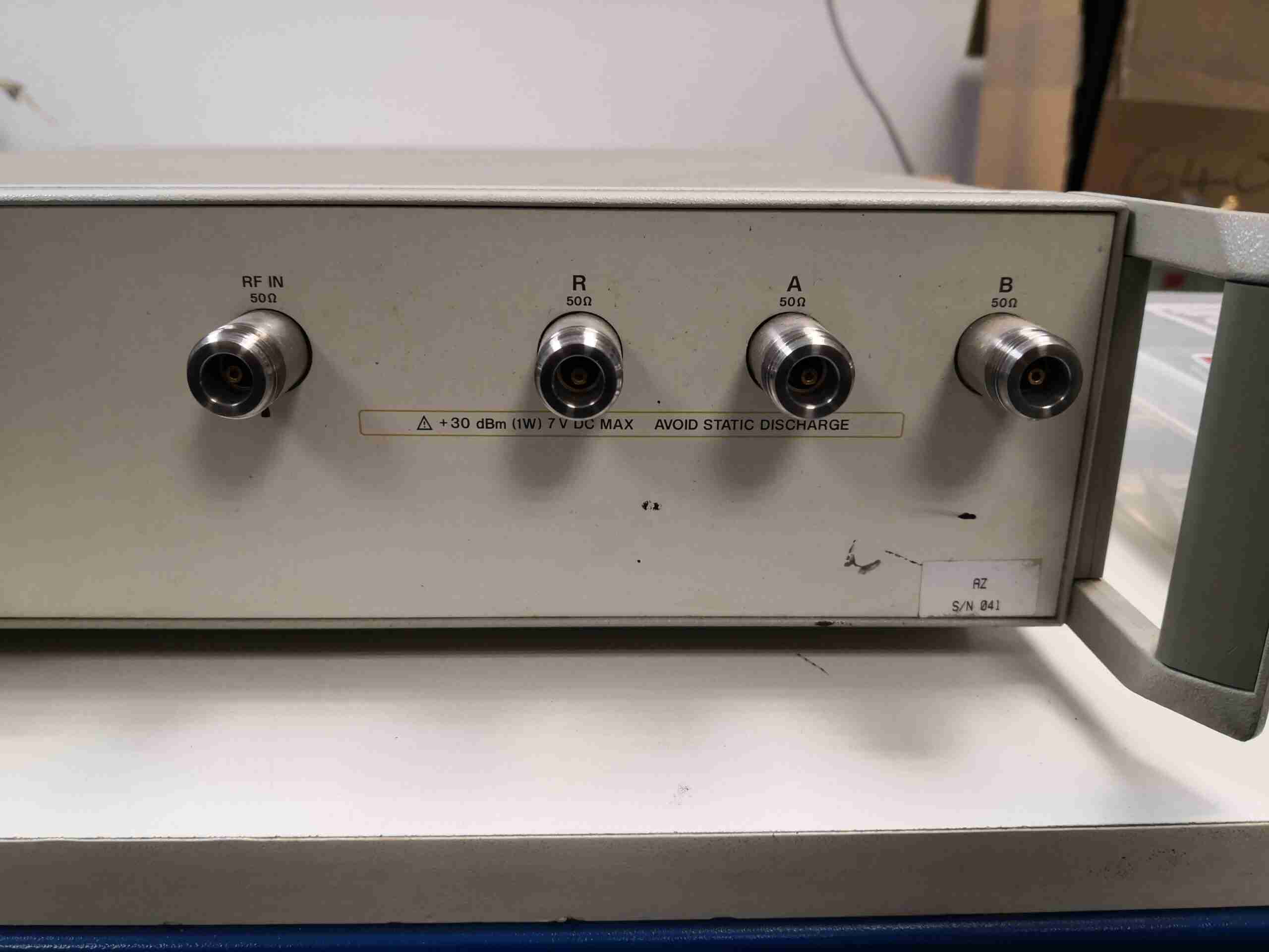
The interconnects for the RF input, Reference output back to the analyser, A&B ports are N-Type, and should be connected to the main unit with phase-matched cables.
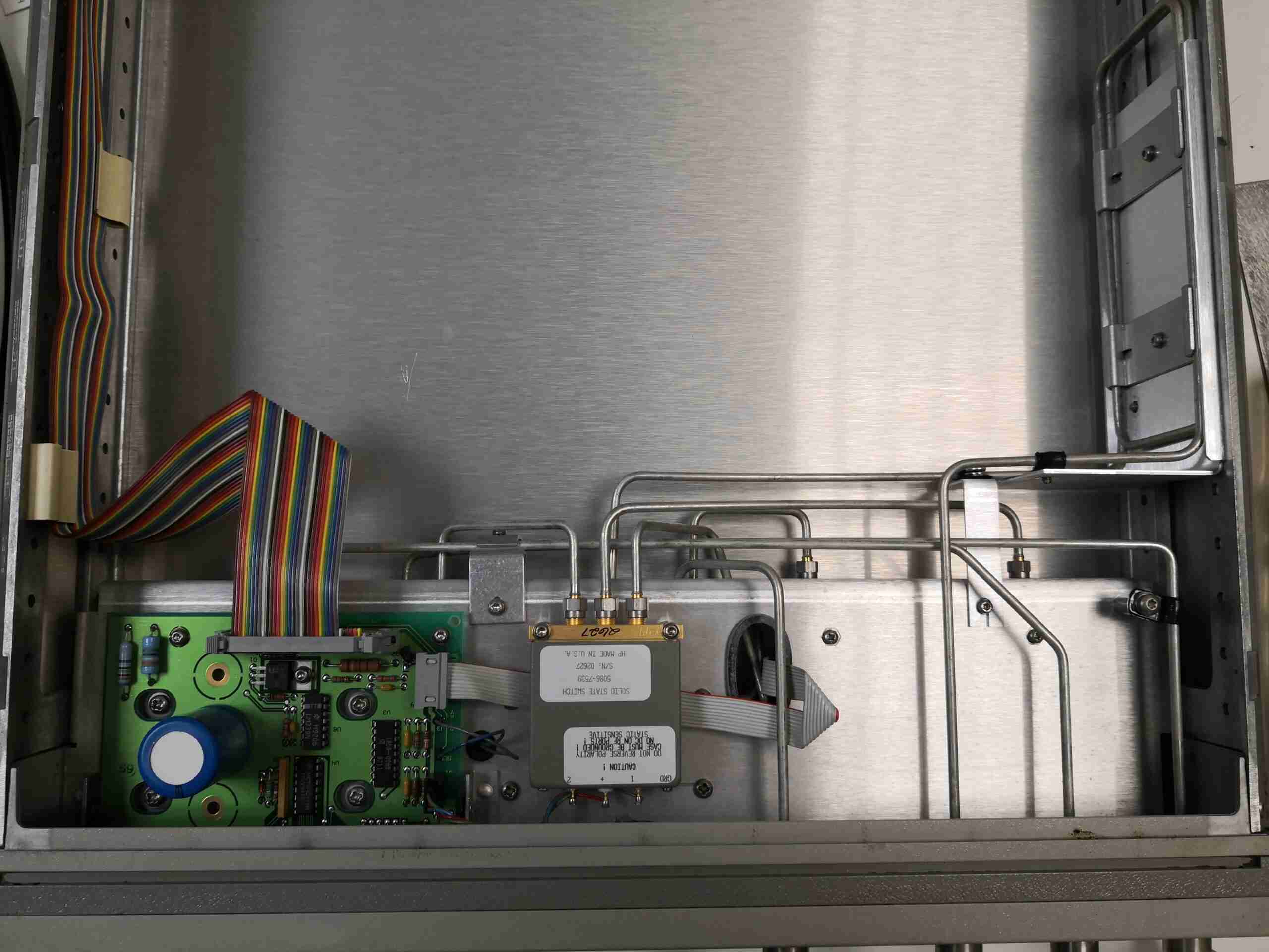
On removing the lid, it’s almost a completely empty box! All the RF magic is done in the first 150mm behind the front pane, apart from a coil of semi-rigid coax on the right, which will be to match the lengths of cables in the unit for phase purposes. There’s not much visible on the top here, just the control board, which takes signalling from the main analyser unit, and only has some glue logic & comparators. There’s a very nice 3-port solid-state RF switch in the centre, for switching between S12 & S21 measurements rapidly, a function that would not be possible with a mechanical relay. All the internal connections are made with semi-rigid coaxial cable, fitted with SMA connectors.
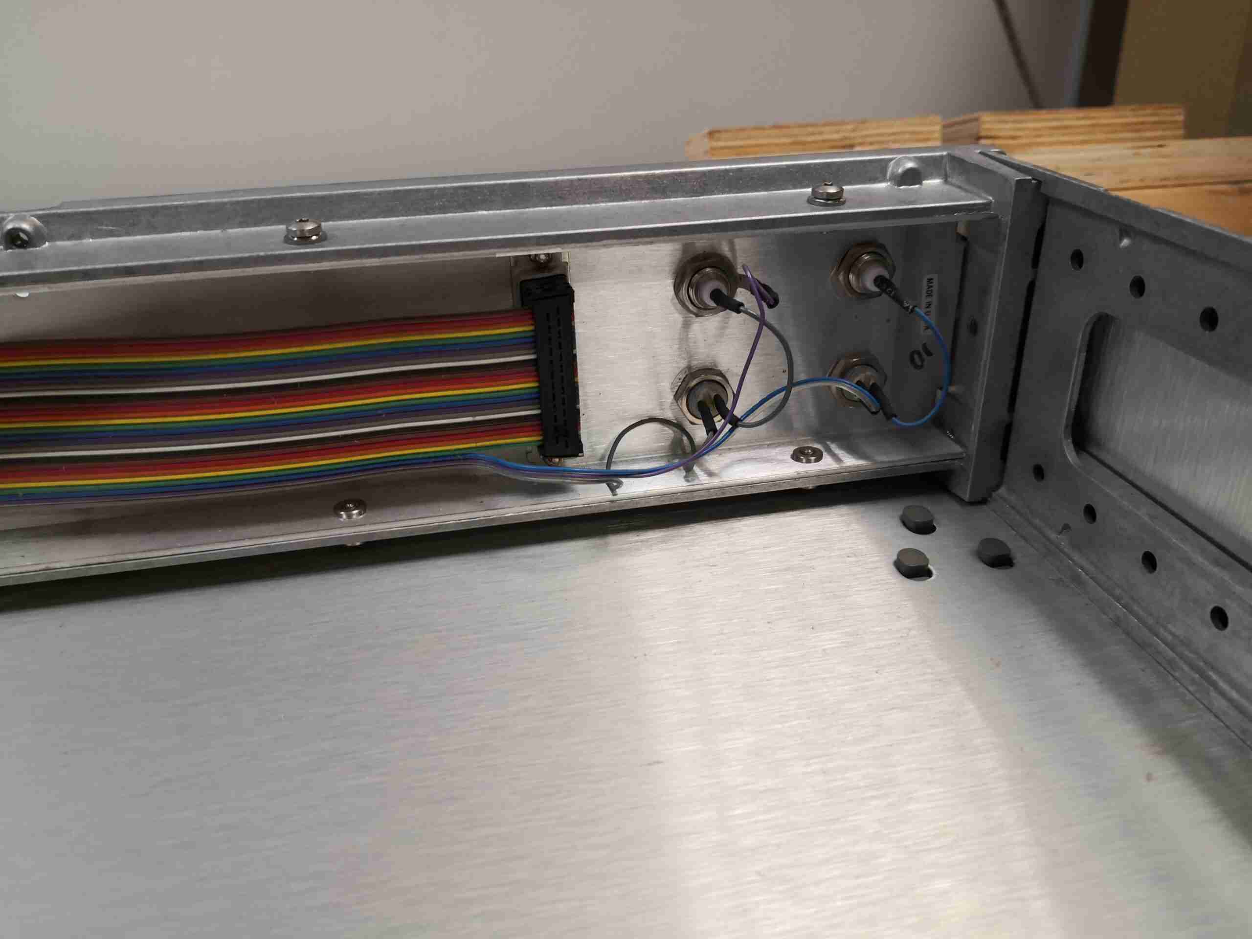
The back of the case just has the 25-way D connector for control, and a pair of BNC connections & 500mA fuses for DC biasing the output ports where required by the EUT.
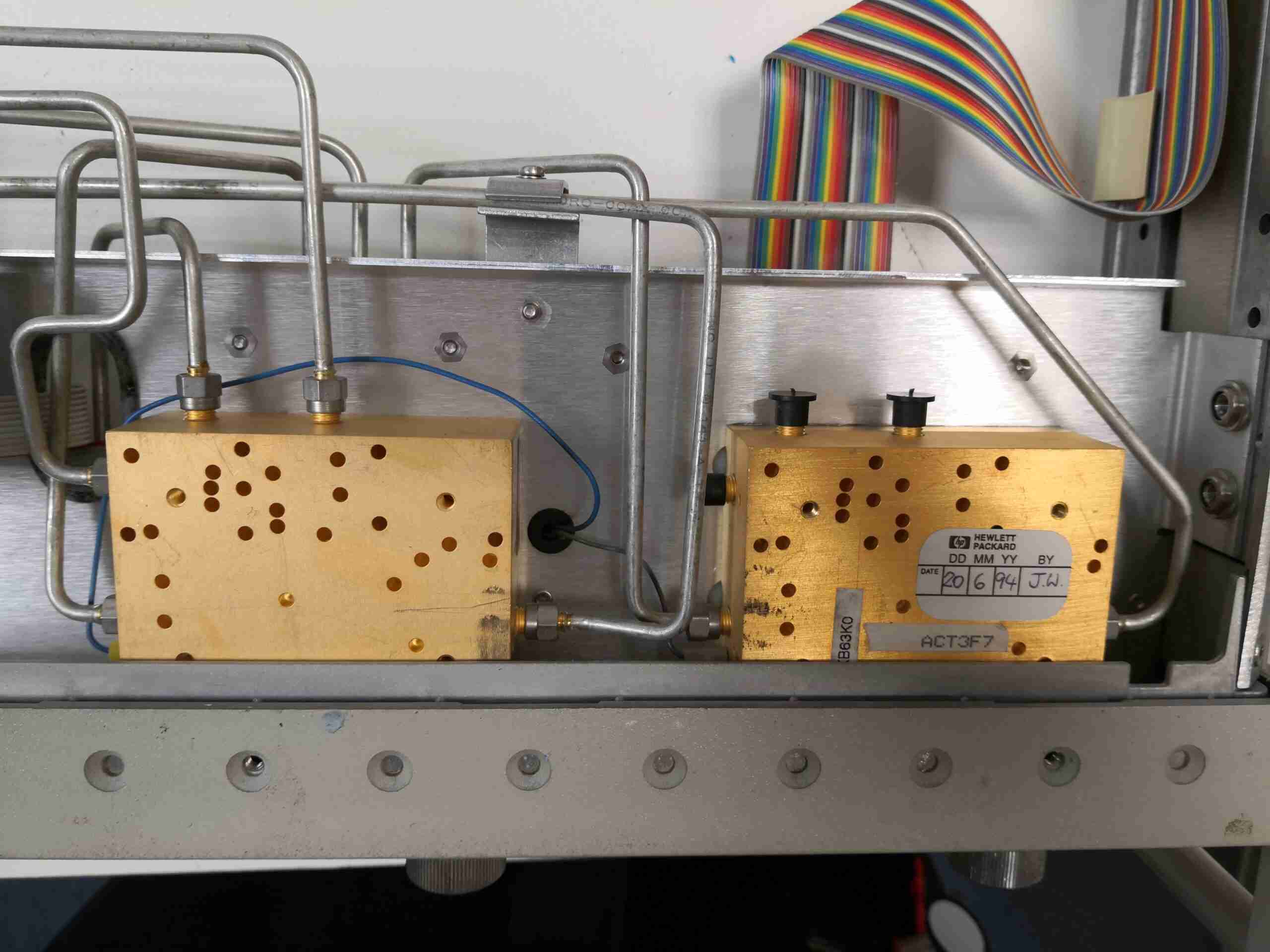
Underneath the centre panel is where most of the RF magic happens. These two blocks, which are integrated with the test ports contain bias tees for each port, a power splitter for the RF reference back to the analyser & directional couplers for reading back the forward & reverse RF power from each test port.
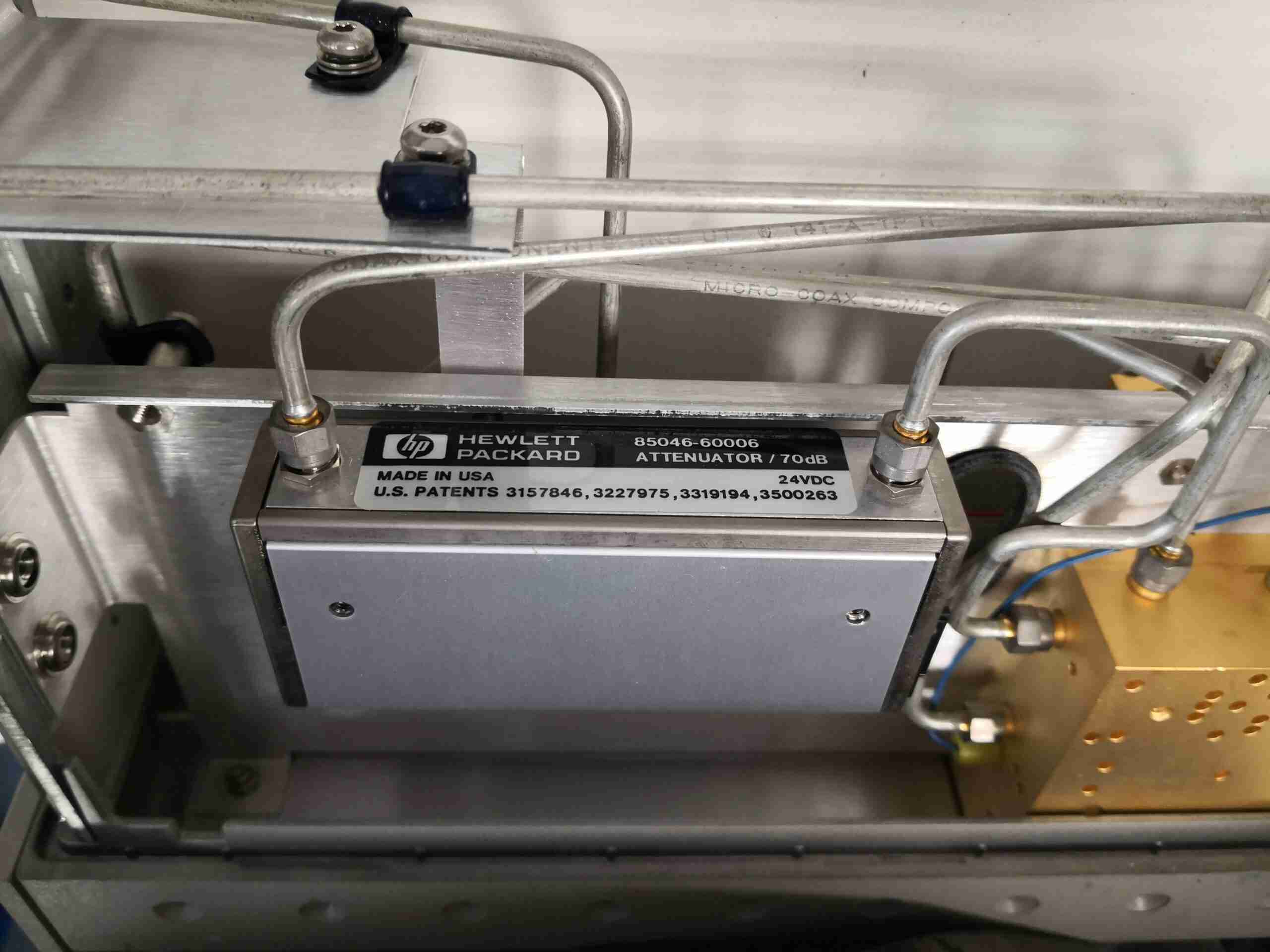
The final component in here is a 70dB step attenuator, adjustable in 10dB steps.
