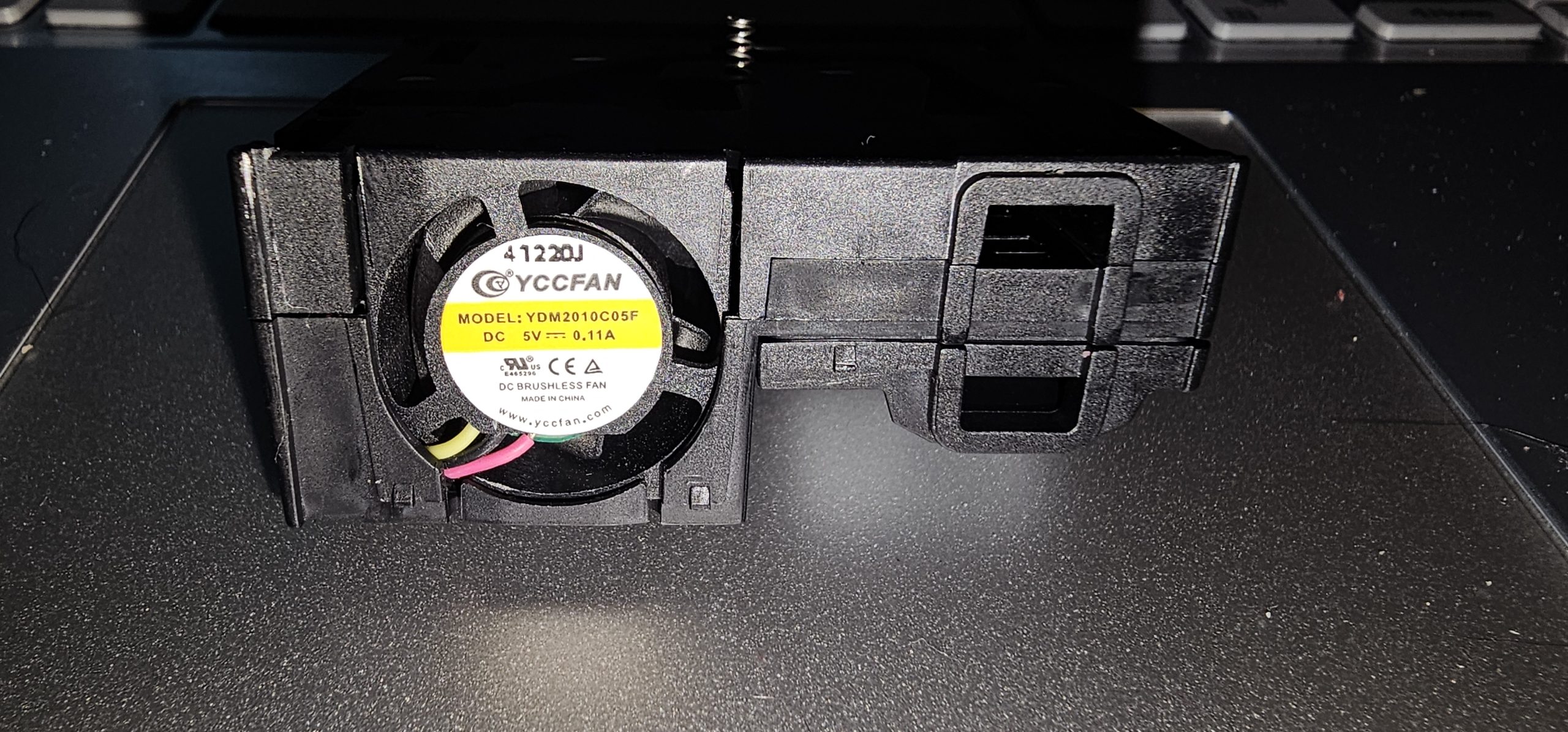
Here’s something a bit different – the Sensirion SEN55, an all-in-one air quality module which measures particulates (PM1.0, 2.5, 4.0 & 10), VOC and NOx indices, and humidity & temperature, over I²C or UART. I wanted to see what was inside without wrecking it, so this is a non-destructive teardown.
The obvious features from the outside are the fan on the left, and the two rectangular air ports on the right hand end. The fan is a YCCFAN YDM2010C05F, a 5V brushless unit rated at 0.11A. It has three wires (yellow, green and pink) rather than the usual two, and the third is probably a tacho signal, which would fit with the sensor being able to report a fan speed warning. The housing is split into 3 parts, the “top” smallest part has a HEPA filter underneath for creating clean “sheath” air, ensuring that dust does not get on the PM sensor element itself. The larger of the two parts appears to be either bonded or clipped somewhere I can’t see, so the teardown did not go any further than the top cover and the metallic shield.
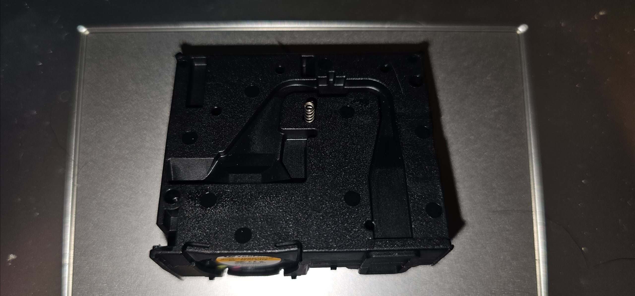
With the shield removed, the inside of one half is a moulded air duct. The channel walls guide the airflow from the fan around to the measurement chamber, and there’s a small steel coil spring standing in a pocket in the middle of it. The spring contacts the PCB in the bottom of the hole, and ensures that the shield is electrically grounded for EMI suppression. There are lots of round holes and bosses scattered over the moulding, some of which presumably line up with the posts that hold the PCB in place in the other half.
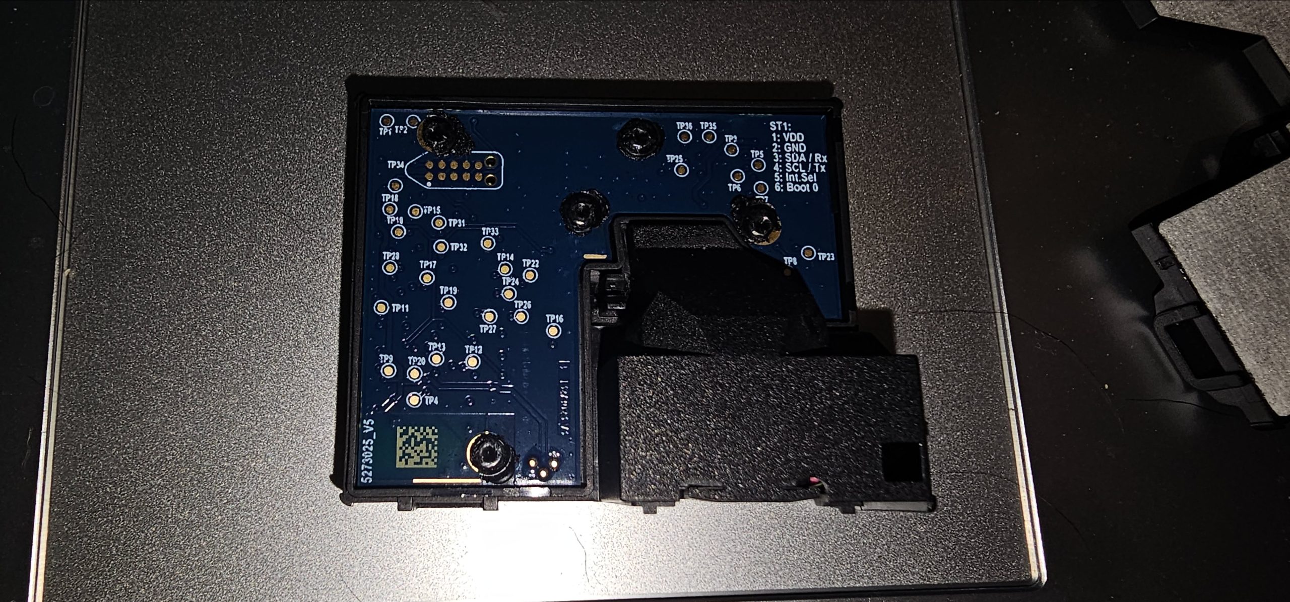
The other half carries the PCB, and this side is entirely test points, with no components fitted at all – the actual chips must be on the far side, under the optical chamber. The board is held in with five black plastic posts, which look to have been heat-staked (melted over), so the PCB stays where it is unless I want to break something, which is as far as a non-destructive teardown goes. At top left is a 10-pad footprint marked TP34, which looks like a pogo-pin (Tag-Connect style) programming or test connector. The board is marked 5273025_V5, with a DataMatrix code near the bottom.
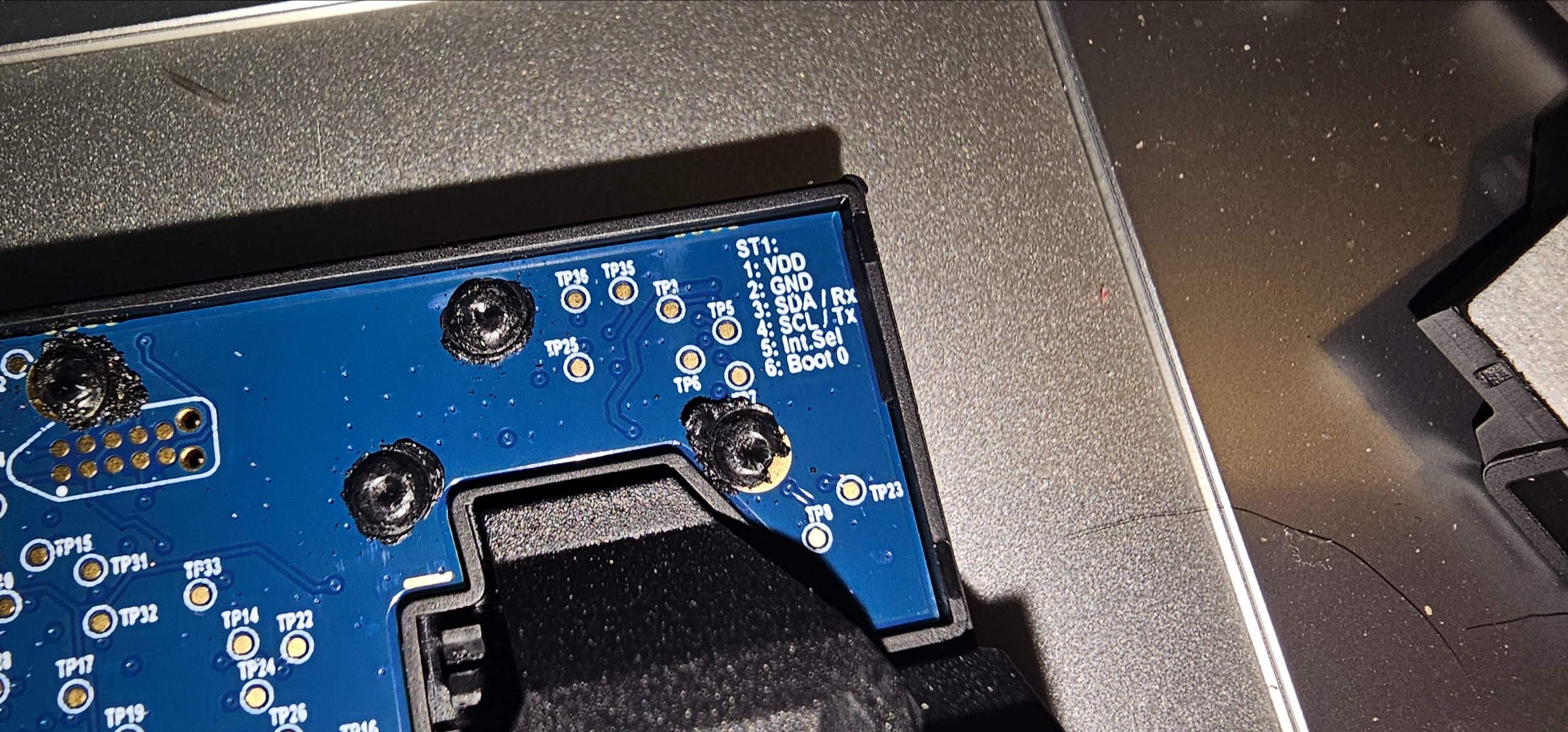
Closer in at the top right, the silkscreen gives the pinout of the module’s ST1 connector: 1: VDD, 2: GND, 3: SDA / Rx, 4: SCL / Tx, 5: Int.Sel and 6: Boot 0. There is no specification in the datasheet for UART, just I²C, and Pin 5 is specified in the datasheet as “connect to GND”. Pin 6, “Boot 0”, is interesting – presumably a bootloader entry pin for the internal microcontroller, and not something that’s needed in normal use.
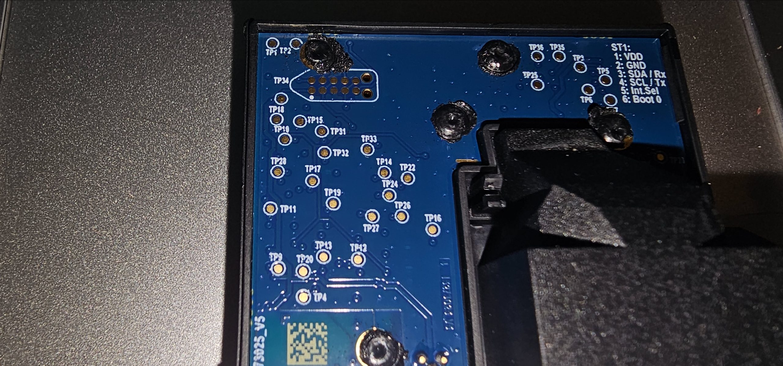
The rest of the board is a field of numbered test points, running from TP1 up to at least TP36. That’s very much a production test fixture layout, designed for a bed-of-nails jig rather than a person with a multimeter, but they’d be useful for getting at the internal signals if you had a set of fine probes and some patience.
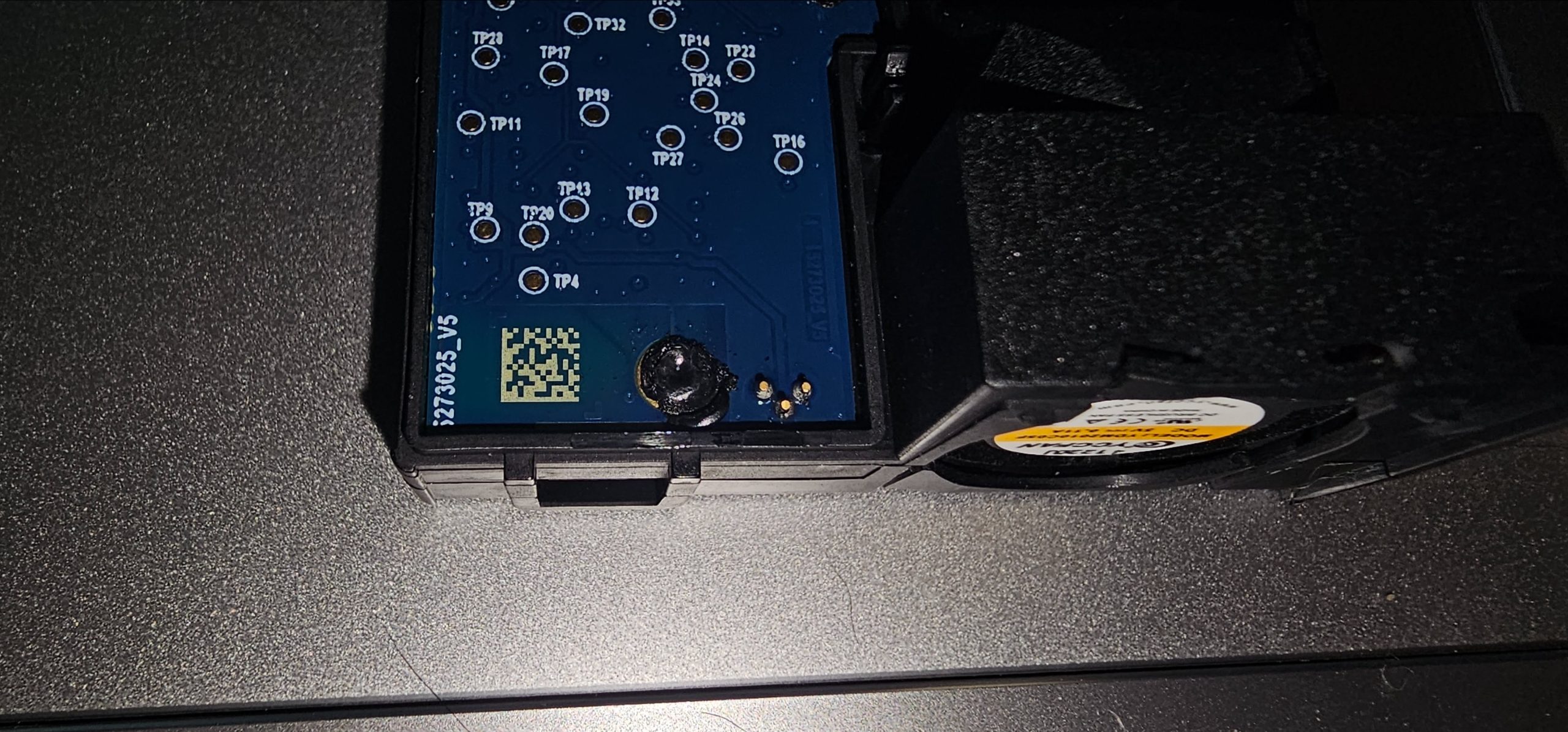
At the bottom edge, next to the fan, are three small pads, which are probably where the fan’s three wires connect to the board – the fan leads emerge close by. The DataMatrix code alongside will be for production traceability.
Having seen how directly the fan is coupled to the air path, it’s easy to see why Sensirion built a fan cleaning routine into the sensor: it runs the fan at maximum speed for about 10 seconds to shift accumulated dust, and by default the module does this automatically once a week. It can also be triggered manually through the interface.