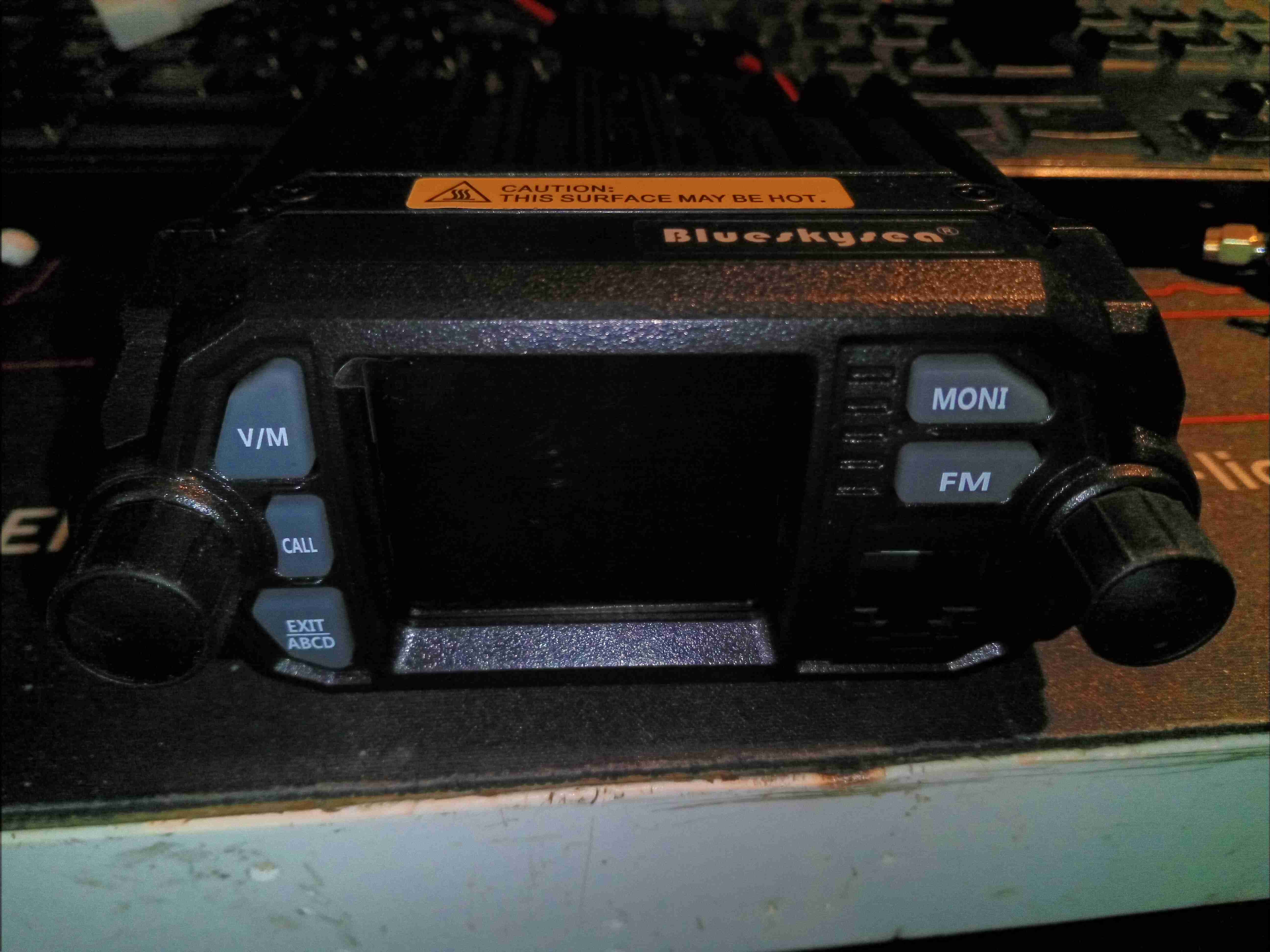
Here’s a miniature-sized mobile rig, which I purchased from eBay to fit in the car – my main Wouxun radio is far too big to fit under the dash! This unit is not much bigger than a UV-5R and cost less than £60! The front panel has a colour TFT LCD for the user interface, with a standard pot for volume, and rotary encoder for menu actions. Most of the controls are actually on the DTMF PTT mic, but some things are operable from the front panel.
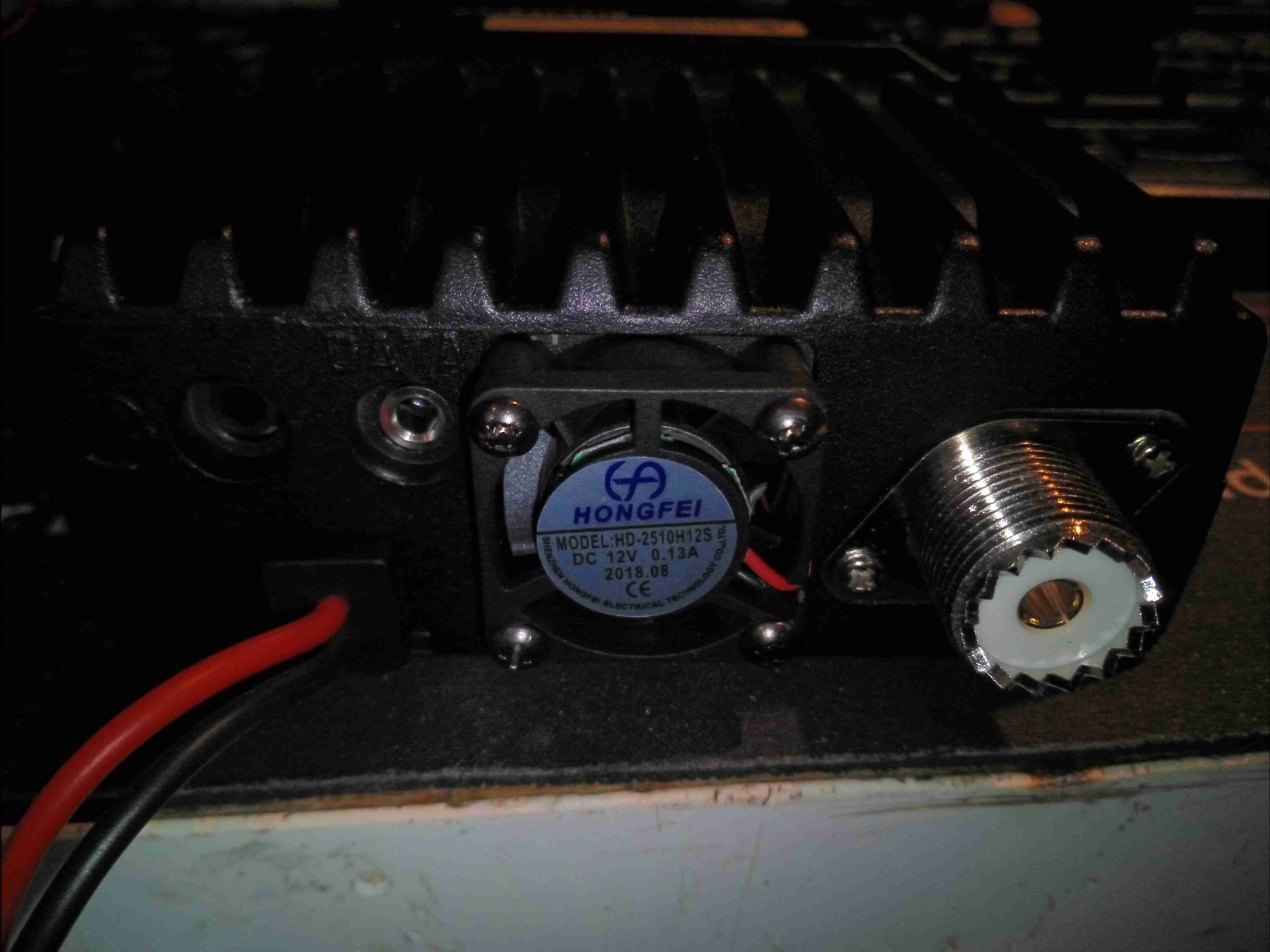
The rear panel has a small fan to cool the internal RF power amp, and a PL-259 connector for the antenna connection. This will be the first thing to be replaced, with an N-Type. There’s also a headset connector on the back, along with a 3.5mm TRS jack for serial data – very important on this radio for programming, as the interface is abysmal in this department ;).
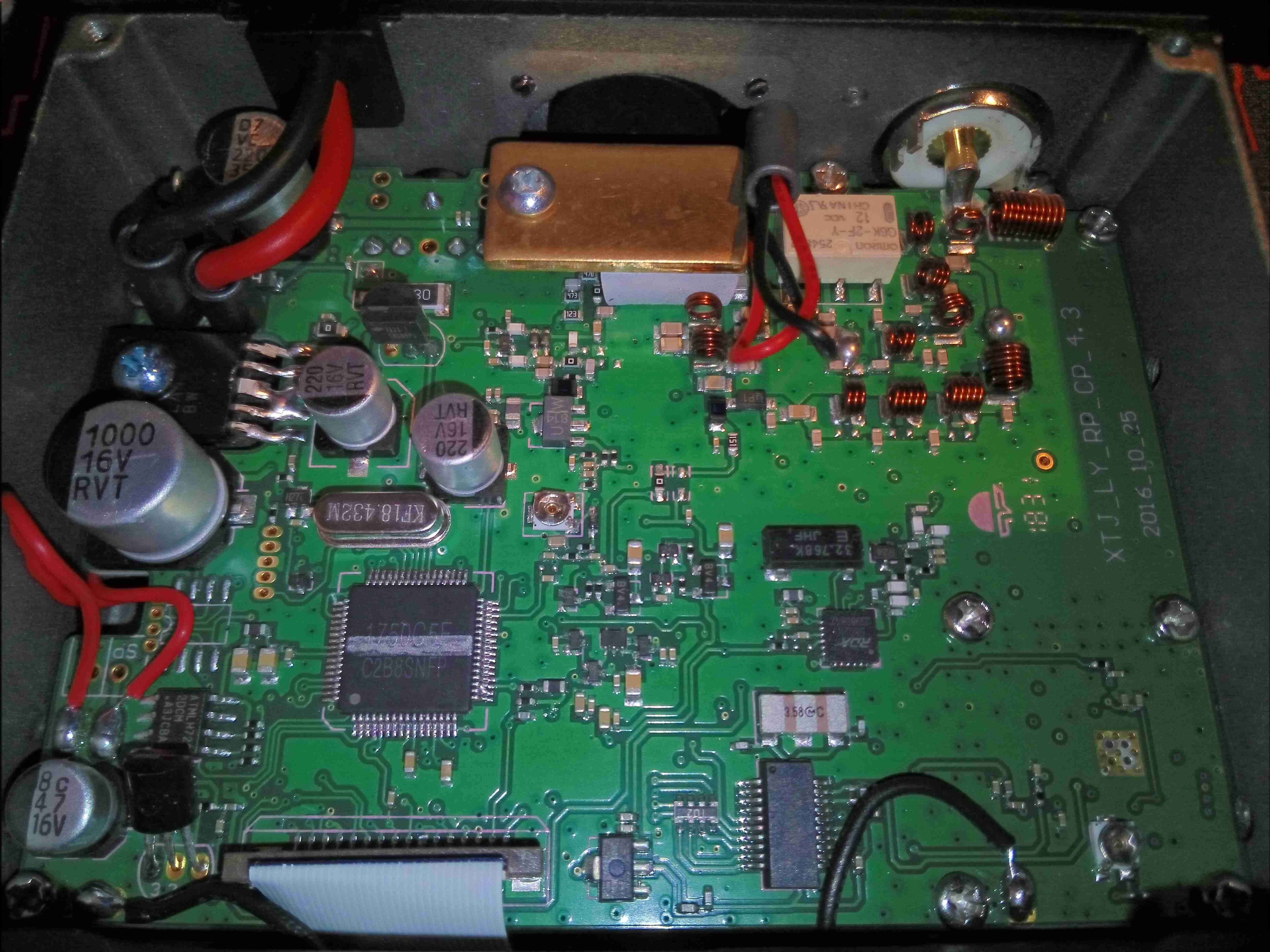
Popping the plastic bottom cover off allows access to the internals. There’s a single PCB in here with a double-sided load. Unfortunately the PCB is too difficult to remove from the casing without damaging anything, so only this side to be seen! On the top though is the main system microcontroller, the broadcast FM receiver, voltage regulation and the RF output stages.
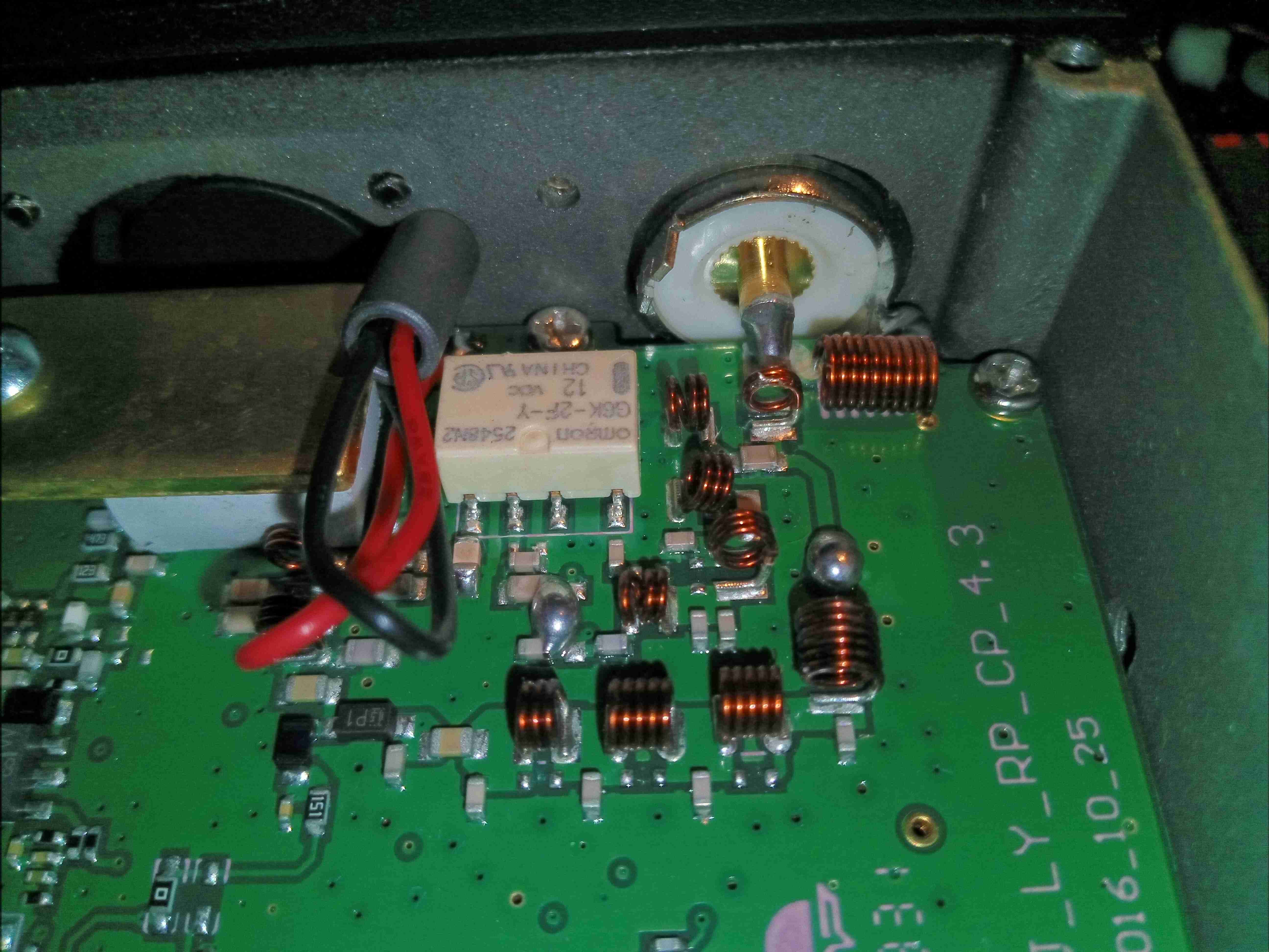
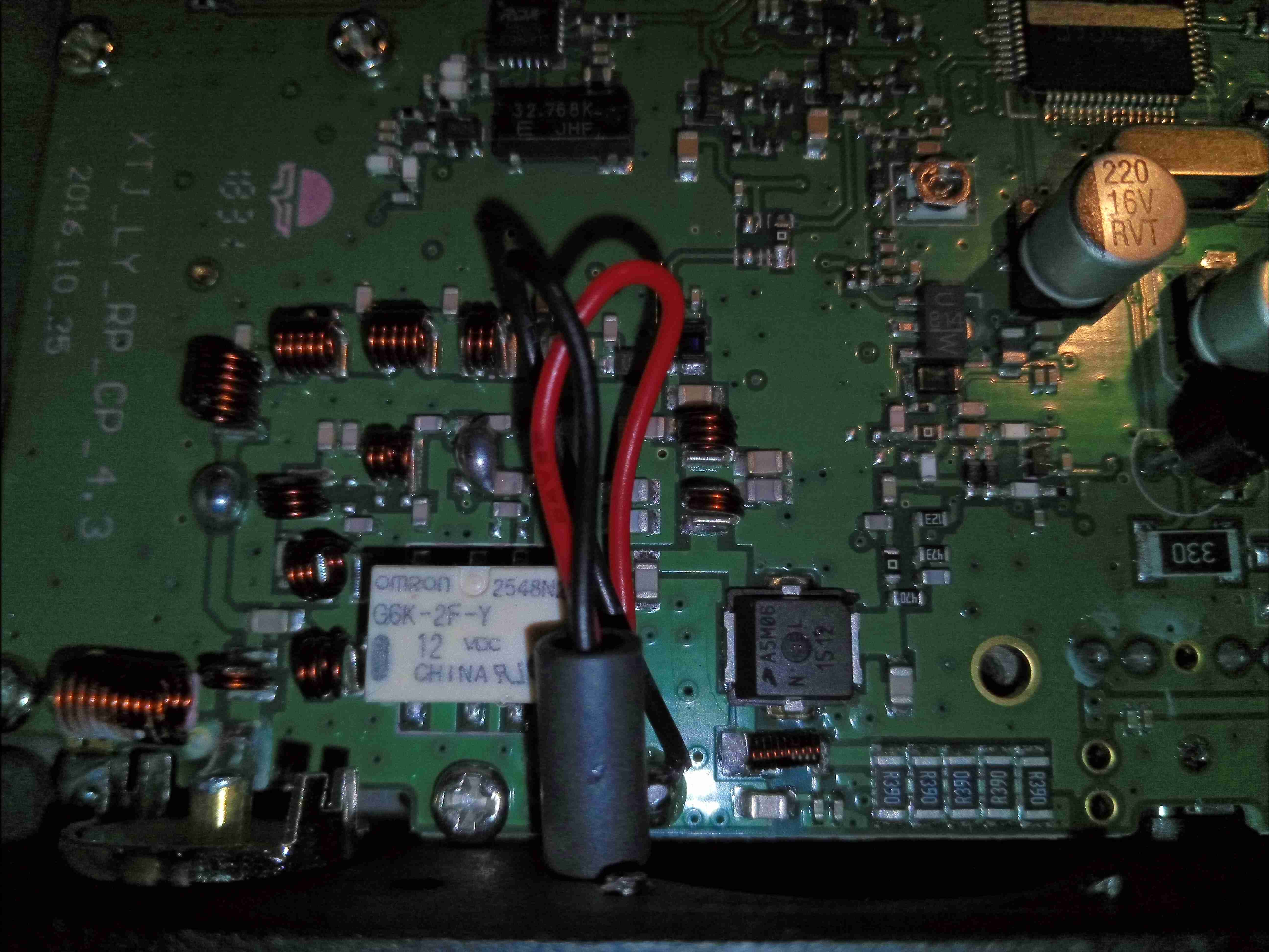
The RF output filters are tucked into a corner of the board near the antenna connector, with a small relay to switch between VHF & UHF. My concern with this relay is that it’s not intended for RF use, and is in fact a general purpose relay. This would have been designed into the unit as a price reduction measure. Under the brass plate & thick SIL pad is the main RF output transistor. The external fan leads also pass very close to the RF output stage, so they may end up radiating some RF from the back of the unit, despite the ferrite bead on the leads.
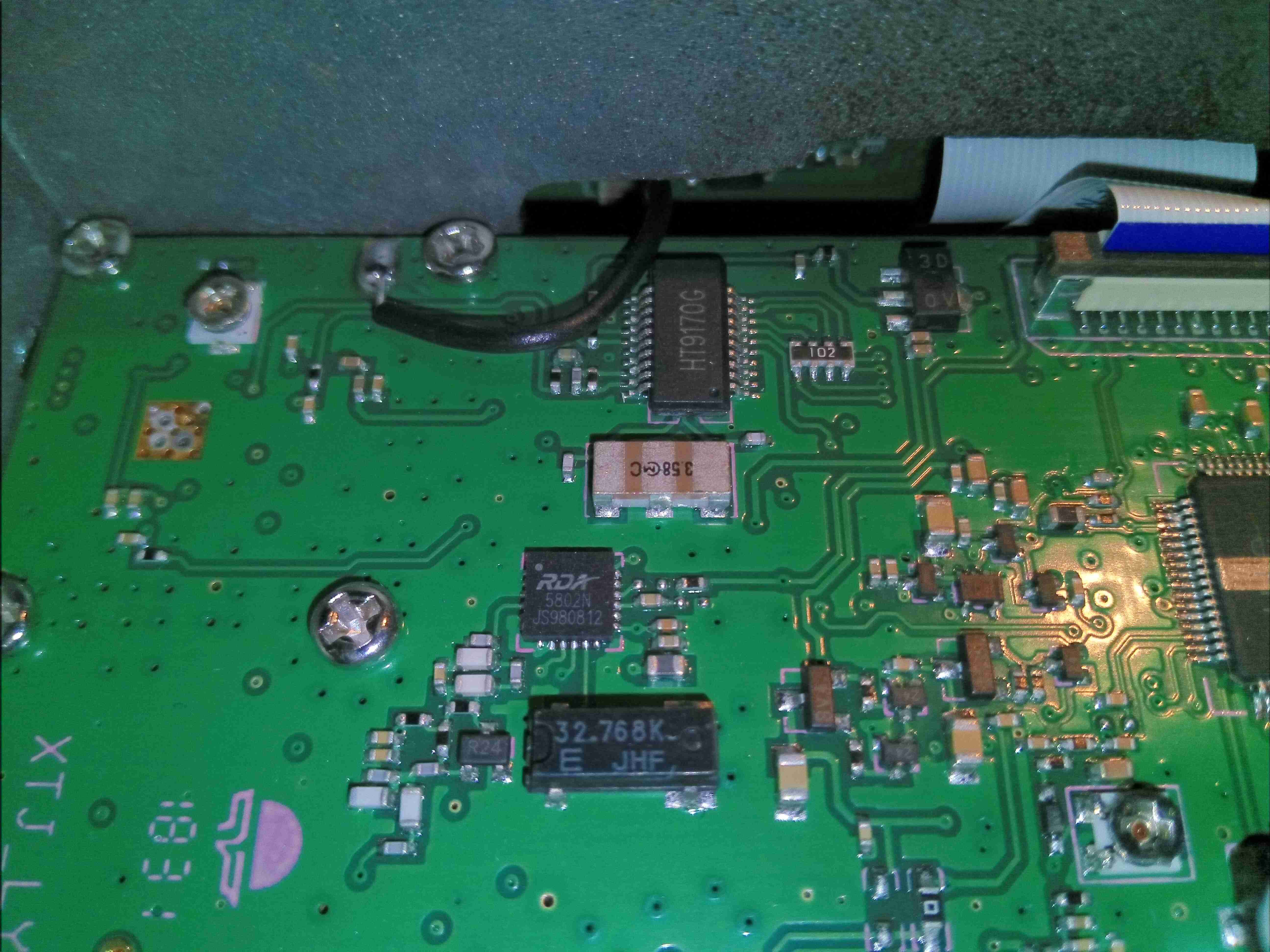
Just behind the front panel is the broadcast FM receiver, an RDA5802, with it’s 32.768kHz clock crystal. Just above that is the DTMF receiver & decoder, used in most Chinese radios, with it’s ceramic resonator. There’s a couple of unmarked pots on the board, but I am not certain what their function is.
Here’s the RF output stage, with the “heatsink” removed. I’m concerned on several fronts with this part – the heatsinking provided by a small brass plate and thick SIL pad is going to be poor at best, but looking at the datasheet for the main RF transistor, an AFT05MS006NT1 RF LDMOS N-Channel Lateral MOSFET from NXP shows some alarming numbers. Grab the full datasheet [download id=”7839″].
Remember that this radio is intended for mobile use in vehicles – the electrical systems of which can in a normal operational state rise to 14.8v.
This transistor is intended for handheld radio use, with an operational voltage of 7.5v, and absolute maximum ratings of 12.5v! Even when used on a regulated 13.8v PSU, the absolute maximum rating for the transistor is being exceeded.
At the very least, I would expect the life of the radio to be shortened due to this problem, and at worst the transistor may catastrophically fail in service, damaging the radio.
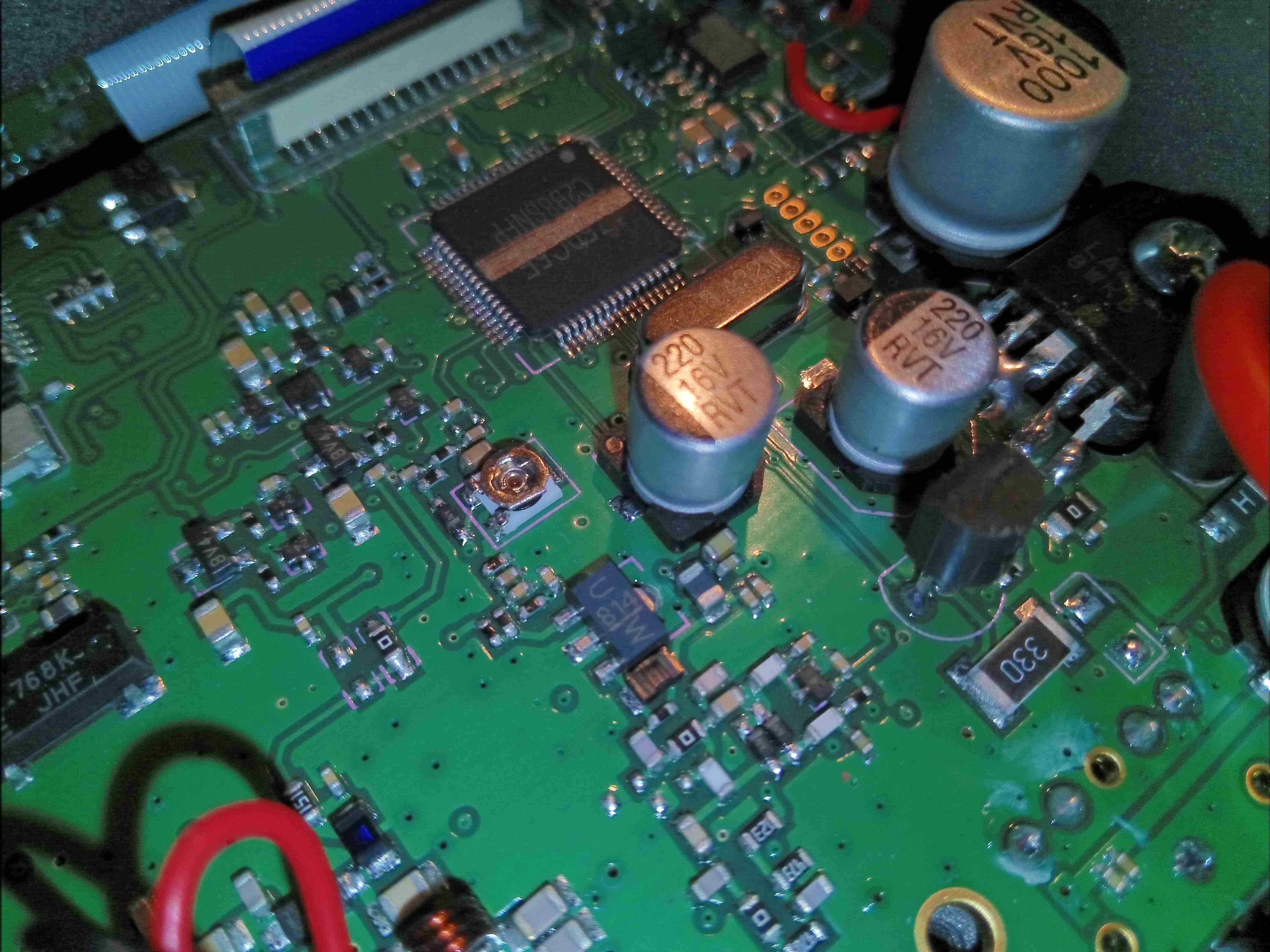
The main microcontroller is a Renesas R8C series device, with quite a few peripherals. It is accompanied by it’s clock crystal, and a programming header. An FFC cable vanishes off to the front panel PCB for driving the LCD & connecting up the user controls & mic connector. Just to the right is the main voltage regulation section for the electronics, minus the RF output stage, which is directly connected to the DC input bus.
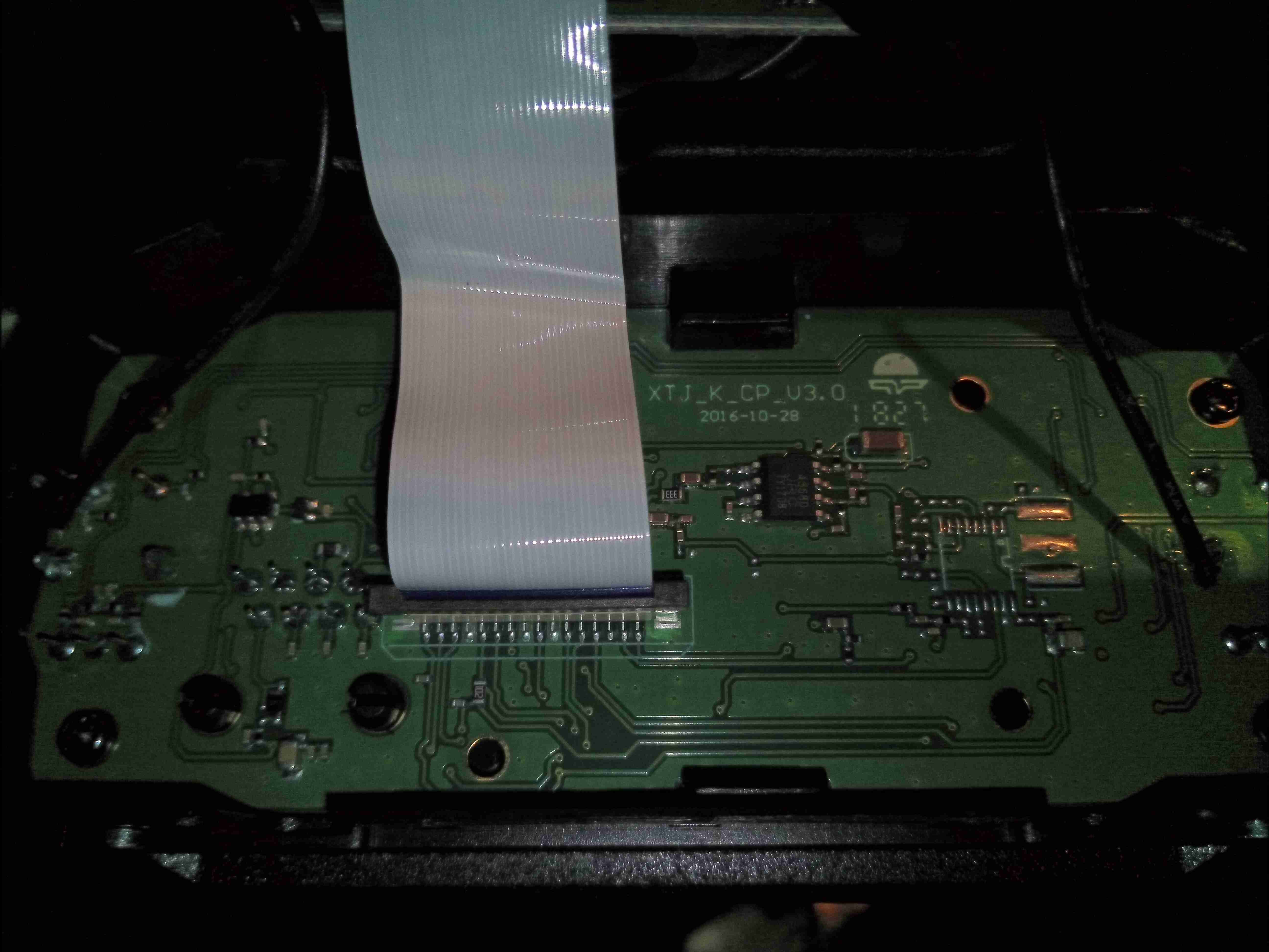
There’s not much on the front panel PCB, so I won’t bother taking it out of the frame, this is going to mainly be interconnects for the SPI/I²C driven LCD & analogue channels for the audio.
I’ll keep the blog posted with lifespan checks on this radio, as I’m definitely concerned about the power amplifier transistor, but other than that it seems to be an OK radio. The rotary encoder has zero debounce, so it doesn’t work properly, but this isn’t much of an issue when the radio is fully operable from the PTT mic.

Very interesting post, I am sure this info will come in handy – thank you.
Consulta,cómo se puede desactivar la entrada de FM,gracias
Any thoughts on a more proper output transistor?
My KT-8900D has dropped to 5 w output for UHF and 8w on VHF.
I strongly suspect the output transistor is failing, but not dead yet.
Hi Charley,
To be honest, just improving the heatsinking of the output stage would improve things – SMD packages are not intended to be cooled via a SIL pad on the top, even though the Chinese love this method. I suspect the transistor has got rather toasty & is cooking itself on TX. Changing the transistor for something else is most likely going to be a very difficult task, as careful RF redesign would be required, along with a re-alignment. Perhaps giving the transistor some more cooling via the bottom of the PCB to the case would help?
Cheers
de 2E0GXE
its not a 7.5v volts rf bro its 30v as you said
I agree with the relay switch is inappropriate but was a cost effective solution.
If you remove the PCB out from the aluminium case, there is actually a heatsink at the bottom side of the PCB that I think is the main heatsink, at least in my unit.
RF choke used were under-rated. This is common cause of failure.
Filters are broadband, it allows FM broadcast that desensitize the Rx.
The RF Power Transistor is rated to operate at 12.5V, with a test data taken at 7.5V, while the absolute maximum is 30V. I believe it is ok to operate at 13.8V VDD as long as the Maximum Power Dissipation doesn’t exceed 30W at 90C case temperature.
Surprisingly, my units actually survived with so much abuse in my experiments and use.
I have two Retevis RT73 fail in the Dallas, TX heat with just using the radio on VHF full power for APRS. So maybe a 2 second burst every 2 minutes. First radio died within 6 months and 2nd radio 9 months.
Meanwhile NXP stopped manufacturing of this transistor, so a good replacement would be more than welcome.
Greetings from Brazil, I need the kt-7900d schematic, my radio is blocked for TX. thanks 73
Use qyt software to address and fix your issue sir!!
Boa noite!
kt-7900d toda hora do nada bloqueia para TX e RX. Tenho que usar o software qyt para resolver e corrigir o problema, acontece que o problema volta. Como resolver de forma definitiva?
obrigado 73
Correct replacement final transistor is AFT09MS015N, about $6 from Mouser. This part is tested to 20+W @870 MHz. I cannot imagine the AFT05MS006NT1 putting out 20 or 25 watts.
I blew the idiot diode on this model. Yes I’m an idiot.
Where is the reverse polarity diode located?
Can it be bypassed? Yes I know if I bypass I’m screwed if I mess up again.
Please help. I can fix computers all day, I’m new to radios.
It’s not really clear on the photos where the reverse polarity protection diode is, but it will be near the input power wires if there is one – the input MAY go straight into the regulator though!
The relay (G6K-2F-Y) does not switch when I press the ptt button. Where can the error be?
Hello! In the RF output stage photo above, does anyone know (or can speculate) what the purpose is of the (5) R390 resistors in parallel? Is this a current/power measurement circuit? It seems to be feeding right off the main output transistor output. The BFT UV-25X4, which is of similar design presently has only (3) R390s installed (2 pads empty), while earlier versions have (5) R360s.
I have a KT8900R, looks like the same board as your KT8900D. The fan stopped working in it. When I switch from memory to the vfo there is a ticking noise. Radio still seems to function properly. Any thoughts on where the thermal switch is that operates the fan? Or wiring the fan constantly on?
I have a KT 8900 rr seems to be the same board as your 8900d. The fan has stopped working in mine. Also at the same time when I switch to the vfo instead of memory it makes a continuous slow tick noise. Any ideas on where the thermal switch is for the fan? Or maybe rewiring the fan so it’s permanently on?
I accidentally grounded pin 5 on the audio power amp (needed a switch power source) and now a road map / layout would sure be helpful… Thanks again for the schematic diagram – the numbers on the transistors aren’t exactly as shown on the diagram. Thank again from Texas US. 73 de nu5d op steve