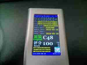
Apple’s Lightning cables are one of a new breed of cable – these have active electronics in the connectors, to allow the device to identify the type of cable being used. This is a little unit that reads out all the internal parameters of the ID chip inside the connector. As can be seen from the image above, the ID chip contains quite a bit of information, from device manufacturer & serial number to chip type & date of manufacture. This unit also gives a “score” of whether the cable is a genuine Apple type, or a Chinese clone, with a scale of 0-100.
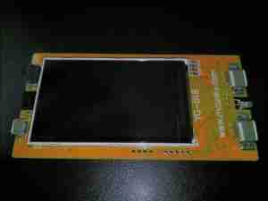
Pulling the PCB from the extruded aluminium case shows the large TFT LCD on the front of the board, with the µUSB charging port on the left side of the board, with the power switch & beeper. The right hand side of the board has a pair of Lightning connectors, which appear to be connected in parallel, and a status LED.
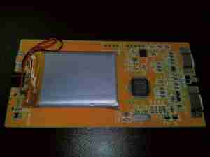
The rear of the PCB has all the electronics, along with the small Li-Po cell used for power. Next to the battery on the left is a 3.3v linear regulator. The right side of the board has the main microcontroller and support electronics.
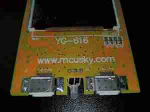
Here’s a closeup of the connector end of the board, with the manufacturer’s web address clearly marked. Heading over to the website shows a company which produces all types of industrial electronics test equipment.
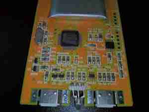
Here’s where the magic happens. There’s a large microcontroller in the centre, which unfortunately has had the number scrubbed off, but it’s probably an STM32 variant, going off the ST-LINK SWD programming port. There’s a TP4056 lithium charger IC, and some discreet NPN transistors. The only other active component here is the IP4220 ESD Protection diode pack. Rather handily, all the component value identifiers are printed on the PCB silkscreen, apart from the microcontroller part number!
